Embed Size (px)
Citation preview


Easy Add-on Projects for the
Spectrum, ZX81 and Ace.
Owen Bishop
1983

This book has been recreated by theJupiter Ace Archive Team 2013
with LATEX
For all ZX Spectrum, ZX81 and Jupiter ACE Users
Contents
PageINTRODUCTION . . . . . . . . . . . . . . . . . . . 1
Interfacing to microcomputers . . . . . . . . . . 1Logic Levels in computer . . . . . . . . . . . . 1The microprocessor . . . . . . . . . . . . . . . . 2Address decoder . . . . . . . . . . . . . . . . . 6Using the ZX Computers . . . . . . . . . . . . 8Using the Jupiter Ace . . . . . . . . . . . . . . 9Using other computers . . . . . . . . . . . . . . 10
PROJECT 1: PULSE DETECTOR . . . . . . . . . 11How it works . . . . . . . . . . . . . . . . . . . 11Building it . . . . . . . . . . . . . . . . . . . . . 13Using it . . . . . . . . . . . . . . . . . . . . . . 13
PROJECT 2: PICTURE DIGITISER . . . . . . . . 16How it works . . . . . . . . . . . . . . . . . . . 16Addressing . . . . . . . . . . . . . . . . . . . . 21Building it . . . . . . . . . . . . . . . . . . . . . 22Final check . . . . . . . . . . . . . . . . . . . . 26Test program . . . . . . . . . . . . . . . . . . . 27Programming . . . . . . . . . . . . . . . . . . . 28
PROJECT 3: FIVE-KEY PAD . . . . . . . . . . . . 35How it works . . . . . . . . . . . . . . . . . . . 37Addressing . . . . . . . . . . . . . . . . . . . . 39Building it . . . . . . . . . . . . . . . . . . . . . 39Testing . . . . . . . . . . . . . . . . . . . . . . 41
PROJECT 4: MODEL CONTROLLER . . . . . . . 44How it works . . . . . . . . . . . . . . . . . . . 44Building it . . . . . . . . . . . . . . . . . . . . . 48Programming . . . . . . . . . . . . . . . . . . . 51
PROJECT 5: BLEEPER . . . . . . . . . . . . . . . 54
3

How it works . . . . . . . . . . . . . . . . . . . 54Building it . . . . . . . . . . . . . . . . . . . . . 56Programming . . . . . . . . . . . . . . . . . . . 59
PROJECT 6: LAMP FLASHER . . . . . . . . . . . 61How it works . . . . . . . . . . . . . . . . . . . 61Building it . . . . . . . . . . . . . . . . . . . . . 64Programming . . . . . . . . . . . . . . . . . . . 64
PROJECT 7: LIGHT PEN . . . . . . . . . . . . . . 66How it works . . . . . . . . . . . . . . . . . . . 66Building it . . . . . . . . . . . . . . . . . . . . . 68Programming . . . . . . . . . . . . . . . . . . . 71
PROJECT 8: MAGNETIC CATCH . . . . . . . . . 78How it works . . . . . . . . . . . . . . . . . . . 78Building it . . . . . . . . . . . . . . . . . . . . . 84Programming . . . . . . . . . . . . . . . . . . . 85
PROJECT 9: LAP SENSOR . . . . . . . . . . . . . 87How it works . . . . . . . . . . . . . . . . . . . 87Building it . . . . . . . . . . . . . . . . . . . . . 90Programming . . . . . . . . . . . . . . . . . . . 91
PROJECT 10: PHOTO-FLASH . . . . . . . . . . . 94How it works . . . . . . . . . . . . . . . . . . . 95Programming . . . . . . . . . . . . . . . . . . . 99
PROJECT 11: GAME CONTROL . . . . . . . . . . 102How it works . . . . . . . . . . . . . . . . . . . 102Building it . . . . . . . . . . . . . . . . . . . . . 104Programming . . . . . . . . . . . . . . . . . . . 106
PROJECT 12: RAIN DETECTOR . . . . . . . . . . 111How it works . . . . . . . . . . . . . . . . . . . 111Building it . . . . . . . . . . . . . . . . . . . . . 111Programming . . . . . . . . . . . . . . . . . . . 113
PROJECT 13: WEATHERCOCK . . . . . . . . . . 115How it works . . . . . . . . . . . . . . . . . . . 115Building the vane . . . . . . . . . . . . . . . . . 118Addressing . . . . . . . . . . . . . . . . . . . . 119Building the circuit . . . . . . . . . . . . . . . . 121Programming . . . . . . . . . . . . . . . . . . . 121
PROJECT 14: ANEMOMETER . . . . . . . . . . . 124How it works . . . . . . . . . . . . . . . . . . . 125Building it . . . . . . . . . . . . . . . . . . . . . 127Programming . . . . . . . . . . . . . . . . . . . 129
PROJECT 15: THERMOMETER . . . . . . . . . . 131
4

How it works . . . . . . . . . . . . . . . . . . . 131Building it . . . . . . . . . . . . . . . . . . . . . 131Calibration and programming . . . . . . . . . . 133
PROJECT 16: BAROMETER . . . . . . . . . . . . 137How it works . . . . . . . . . . . . . . . . . . . 137Building it . . . . . . . . . . . . . . . . . . . . . 141Programming . . . . . . . . . . . . . . . . . . . 144
PROJECT 17: SUNSHINE RECORDER . . . . . . 149How it works . . . . . . . . . . . . . . . . . . . 149Building it . . . . . . . . . . . . . . . . . . . . . 152
Appendix A:THE ADDRESS DECODER . . . . . . 157Building the project . . . . . . . . . . . . . . . 162Controlling the decoder . . . . . . . . . . . . . 173Programming the ZX81 . . . . . . . . . . . . . 174Programming the Jupiter Ace . . . . . . . . . . 178
Appendix B: PIN LEAD-OUT DETAILS . . . . . . 180SPECIAL NOTE FOR READERS IN USA . . 182

INTRODUCTION
Interfacing to microcomputers
This book describes how to build electronic circuits which youcan attach to your ZX Spectrum, ZX81 or Jupiter Ace. Allthe devices have been tested with all of these computers. Mostof the circuits probably work just as well when connected to aZX80 micro or could be adapted to do so fairly easily, but theyhave not been tested with this computer, and full connectingdetails are not given here.
All the projects are simple and inexpensive ones, requiringonly a few transistors or integrated circuits. The integratedcircuits are of the less expensive kind. The wiring required foreach circuit has been kept to a minimum, an unusual featurefor a book of this kind, for microcomputer projects tends toneed rather more wires than projects of other kinds. The resultof this simplified approach used here is that all the projects canbe built easily and cheaply, even by a relative beginner. Oncebuilt, they are simple to operate. Writing programs to controlthem need not be complicated. Each project includes a simpleprogram or two to get you started. Of course, those readerswho are more expert at programming can have a lot of fun inwriting elaborate programs based on these projects, but thebeginner can start with the short program and perhaps addextra features later.
The circuit designs apply equally well to the ZX81, ZX-Spectrum and the Ace. If you have a ZX81 now and later buya ZX-Spectrum, the projects can be operated from your newcomputer without having to change them. You may need tomodify the program slightly, since the Spectrum has a moreextensive BASIC than the ZX81. The differences are explainedlater.
Logic Levels in computer
Computers deal with numbers and other information as a seriesof 0s and 1s. The projects show many examples of this.
1
The 0s and 1s, or binary digits (shortened to ”bits”) are rep-resented in the computer by voltage levels.
0 is represented by 0V, we refer to this as ”low”.1 is represented by +5V, we refer to this as ”high”.
Numbers and other kinds of information, including instruc-tions, are handled in the computer by making one of these twovoltages (0V or +5V) appear on different wires (or lines).
The microprocessor
Although these computers inay differ in appearance and intheir facilities, their microprocessor (the Z80) is identical ineach.
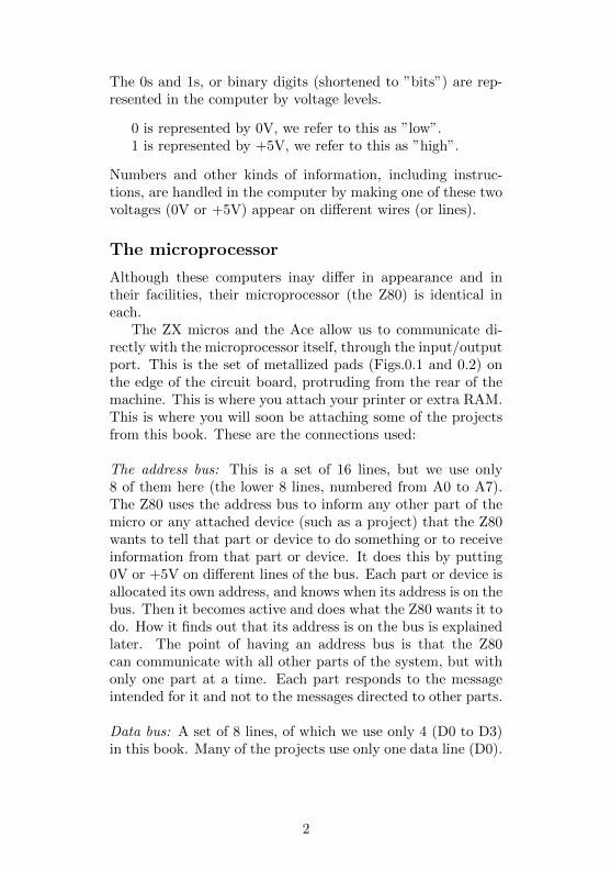
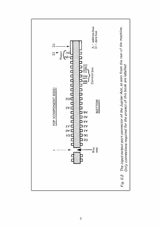
The ZX micros and the Ace allow us to communicate di-rectly with the microprocessor itself, through the input/outputport. This is the set of metallized pads (Figs.0.1 and 0.2) onthe edge of the circuit board, protruding from the rear of themachine. This is where you attach your printer or extra RAM.This is where you will soon be attaching some of the projectsfrom this book. These are the connections used:
The address bus: This is a set of 16 lines, but we use only8 of them here (the lower 8 lines, numbered from A0 to A7).The Z80 uses the address bus to inform any other part of themicro or any attached device (such as a project) that the Z80wants to tell that part or device to do something or to receiveinformation from that part or device. It does this by putting0V or +5V on different lines of the bus. Each part or device isallocated its own address, and knows when its address is on thebus. Then it becomes active and does what the Z80 wants it todo. How it finds out that its address is on the bus is explainedlater. The point of having an address bus is that the Z80can communicate with all other parts of the system, but withonly one part at a time. Each part responds to the messageintended for it and not to the messages directed to other parts.
Data bus: A set of 8 lines, of which we use only 4 (D0 to D3)in this book. Many of the projects use only one data line (D0).
2
3
4

The data bus is used for transferring data (instructions or num-bers) between the Z80 and other parts of the system (includingprojects). The data is represented by the voltage levels put onto its lines by the Z80 when it is sending data to another partof the system, or put there by another part of the system whenit is sending data to the Z80.
Input-output-request line: This is one of the control lines, usu-ally called IORQ for short. The voltage level on this line isnormally +5V (high) but, when the Z80 wants to communi-cate with a device which is attached to the micro (such as aproject), it makes the level low (0V). The line over the let-ters IORQ mean that the voltage goes low when something isto happen; we say it is ”active-low”. The low level on IORQalerts the device to the fact that the Z80 has already placed anaddress on the address bus, and the device must check to see ifthis is its own address. The Z80 has another control line called”memory-request” (MEMRQ), which it uses when it wants tocommunicate with its memory. We do not use MEMRQ inthe circuits of this book. Because of this, the projects can notinterfere with the normal working of the memory of the com-puter.
Read line (RD): This is another control line and is active low.The Z80 puts a low level on this line to indicate when it wantsthe addressed device to send data to it. The device shouldrespond by putting the data on the data bus, so that the Z80can read it.
Write line (WA): The Z80 puts a low level on this line whenit wants to send data to a device.
Power lines: We use two of these. All circuits need to beconnected to the 0V line of the micro, because this is the lineagainst which all voltage levels are to be measured. The microshave a regulated +5V line which could be used to power thecircuits of the projects. The difficulty is that there is usuallynot much power to spare, particularly if several devices areconnected to the system at the same time. Instead, we use the
5
+9V line, which comes directly from the ZX or Ace PowerPack. This is an unregulated supply, but a voltage regulatorIC is used to convert this to a regulated +5V supply.
Address decoder
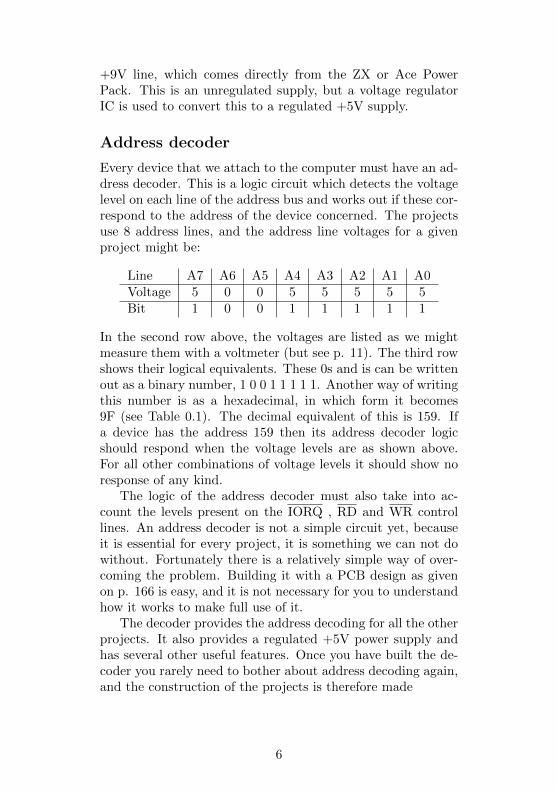
Every device that we attach to the computer must have an ad-dress decoder. This is a logic circuit which detects the voltagelevel on each line of the address bus and works out if these cor-respond to the address of the device concerned. The projectsuse 8 address lines, and the address line voltages for a givenproject might be:
Line A7 A6 A5 A4 A3 A2 A1 A0Voltage 5 0 0 5 5 5 5 5Bit 1 0 0 1 1 1 1 1
In the second row above, the voltages are listed as we mightmeasure them with a voltmeter (but see p. 11). The third rowshows their logical equivalents. These 0s and is can be writtenout as a binary number, 1 0 0 1 1 1 1 1. Another way of writingthis number is as a hexadecimal, in which form it becomes9F (see Table 0.1). The decimal equivalent of this is 159. Ifa device has the address 159 then its address decoder logicshould respond when the voltage levels are as shown above.For all other combinations of voltage levels it should show noresponse of any kind.
The logic of the address decoder must also take into ac-count the levels present on the IORQ , RD and WR controllines. An address decoder is not a simple circuit yet, becauseit is essential for every project, it is something we can not dowithout. Fortunately there is a relatively simple way of over-coming the problem. Building it with a PCB design as givenon p. 166 is easy, and it is not necessary for you to understandhow it works to make full use of it.
The decoder provides the address decoding for all the otherprojects. It also provides a regulated +5V power supply andhas several other useful features. Once you have built the de-coder you rarely need to bother about address decoding again,and the construction of the projects is therefore made
6
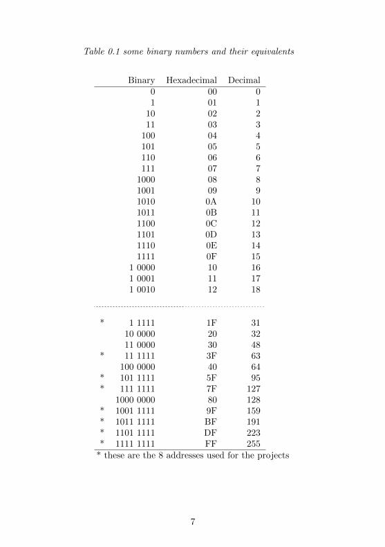
Table 0.1 some binary numbers and their equivalents
Binary Hexadecimal Decimal0 00 01 01 1
10 02 211 03 3
100 04 4101 05 5110 06 6111 07 7
1000 08 81001 09 91010 0A 101011 0B 111100 0C 121101 0D 131110 0E 141111 0F 15
1 0000 10 161 0001 11 171 0010 12 18
* 1 1111 1F 3110 0000 20 3211 0000 30 48
* 11 1111 3F 63100 0000 40 64
* 101 1111 5F 95* 111 1111 7F 127
1000 0000 80 128* 1001 1111 9F 159* 1011 1111 BF 191* 1101 1111 DF 223* 1111 1111 FF 255
* these are the 8 addresses used for the projects
7
much simpler. The decoder itself is not really complicated, forit is easy to understand how it works and, if correctly built,should work perfectly first time. The main complication isthat it has a lot of wires, so you need to take care to makethe correct connections. Fig. D.4 (p. 166) is a printed circuitboard master for this project to help you get the connectionsright. It is also possible to buy this PCB ready-made (seeaddress of supplier, p. 179).
To begin interfacing to your computer, build the decoder.After that, you can choose which of the other projects youwant to make and connect them to the decoder. You canconnect several projects at once, if you wish, yet control themindividually.
Using the ZX Computers
Both of the Spectrum and ZX81 computers use Sinclair BA-SIC, so programs written for one may be adapted for the otherfairly easily. One important way they differ is that the Spec-trum has the IN and OUT commands which allow it to reador write data directly to the input/output port. It is by thesecommands that we control the interfaces. The ZX81 lacks thesetwo commands. Instead of these, we use simple machine-coderoutines, as explained on p. 174.
Of the devices which provide data for the micro to read,most use only the lowest line of the data bus, line D0. It isa property of the logic circuits used in these micros that if aline is unconnected and is not being used, it behaves as if theinput to it is 1. So when we are using only line D0, with linesD1 to D7 unconnected, an input of 0 on line D0 appears as:
1 1 1 1 1 1 1 0
All lines D1 to D7 are ’high’. On the Spectrum the IN com-mand returns 254, the decimal equivalent of this binary num-ber. When line D0 has a ’high’ level on it, the result of a readoperation is 1 1 1 1 1 1 1 1, which is 255 in decimal.
The ZX81 gives different results. The machine-code rou-tine on p. 174, in conjunction with the command LET= USR16514, returns a value which shows the contents of the B and
8
C registers of the microprocessor. The B register always holds1 1 1 1 1 1 1 1 while the C register shows the state of the databus, in the way described above. So if line D0 is ’low’ we get:
1 1 1 1 1 1 1 1 1 1 1 1 1 1 1 0which is 65534 in decimal.
If D0 is ’high’ we get:
1 1 1 1 1 1 1 1 1 1 1 1 1 1 1 1which is 65535 in decimal.
So in the descriptions of programs in this book, you need toadd 65280 to values expected with the Spectrum to find whatvalues are to be expected with the ZX81.
Using the Jupiter Ace
As far as the projects in this book are concerned, the Aceprovides all the connections required. The edge connector onthe Ace board has exactly the same connections as on the ZX81or Spectrum, but on the Ace they are in a different order.The design for the Decoder board therefore needs amendingslightly, or you can make a simple adaptor which brings eachline to its correct position for plugging into a Decoder designedfor the ZX computers.
The main advantage of using the Ace is that its language,FORTH, gives it very high operating speed. This makes itparticularly suitable for the pulse-timing operations requiredby several of the interfaces in this book. Whereas a machine-code program is essential with the ZX computers, for a few ofthe projects the Ace operates fast enough when using FORTH.The FORTH language was, after all, designed to be used incontrolling astronomical telescopes so it is to be expected thatit should excel in controlling other kinds of interface too.
The devices in this book have all been tested with the Aceand work as well on this machine as on the ZX Computers.There is one difference. On the Ace (or at the least on themodel used during the writing of this book), unconnected linesusually read as 0, except for line D4 which reads as 1. Conse-quently, with input to line D0 only, the readings are 32
9

(0001 0000) or 33 (0001 0001) instead of the values found onthe ZX computers. In practice it was found that the values onsome of the unconnected data lines ’floated’ occasionally, read-ing either as 1 or 0 at random. For this reason, it is preferableto AND the data input with the value 0000 0001 to eliminatedany values appearing on the unconnected lines. The commandrequired is:
31 IN 1 AND
where 31 is the address being read from. This sequence leaves0 or 1 on the top of the stack, depending on the state of lineD0.
Using other computers
This book is written for three particular computers but allcomputers which are based on the Z80 or Z80A microproces-sor are the same at heart. Common examples are the Ex-idy Sorceror. Nascom 1 and 2, North Star Horizon, ResearchMachines 380Z, Sharp MX80, Superbrain, Transam Tuscan,TRS-80 and Video Genie. If you can make connections to theaddress bus, data bus and control bus of these machines, asrequired for the decoder (see Fig.D.1) there is no reason whyyou should not attempt to interface these machines with thecircuits described in the book. However, it must be stressedthat the circuits in this book have not been tested with any ofthe machines listed above, so there is no certainty that theywill work. Neither can one be certain that they will not insome way affect the normal operation of the computer, thoughthis is very unlikely. You should also check the terms of theguarantee issued by the manufacturer of the machine to en-sure that you will not be invalidating it by connecting yourown devices to it.
10
Project 1PULSE DETECTOR
This simple device is a very useful one for testing the other in-terfaces. The trouble with micros is that they work very fast.The micro produces pulses of current which may last for onlya fraction of a microsecond. This is far too short a time toaffect an ordinary voltmeter. Even with an oscilloscope it isalmost impossible to pick out the pulse you are interested in.This circuit is designed to detect a low pulse produced by amicrocomputer. The words ’low pulse’ mean that the voltageat the point of testing is normally ’high’ (anything between+2V and +5V), but goes ’low’ (falls below +0.8V) for a shortperiod. This circuit is quick enough to detect low pulses last-ing as little as a fiftieth of a microsecond, which is fast enoughfor almost all pulses that a microcomputer can produce.
How it works
The detecting section of the circuit consists of two logic gates,wired as in Fig.1.1 to make a flip-flop. The output from thissection (at pin 3) may be ’high’ or ’low’, but must be one orthe other. Remember that anything between +2V and +5Vcounts as ’high’, while anything between 0V and +0.8V countsas ’low’. Voltages can not be higher than +5V because that isthe voltage at which we supply power to the circuit.
With the flip-flop in its ’reset’ state, waiting for a pulse toarrive, the output at pin 3 is ’low’. Both of its inputs, theone labelled INPUT and the one labelled RESET are high.INPUT is high because it is connected to the point at which alow pulse is expected at any moment. Although RESET is notconnected to anything (for the button S1 is not being pressed),it acts as if it is high. This is a property of the TTL integratedcircuits used in most of the projects in this book. Any inputwhich is unconnected acts as if it was receiving a high voltagelevel.
The ’low’ output from pin 3 goes to another logic gate,
11
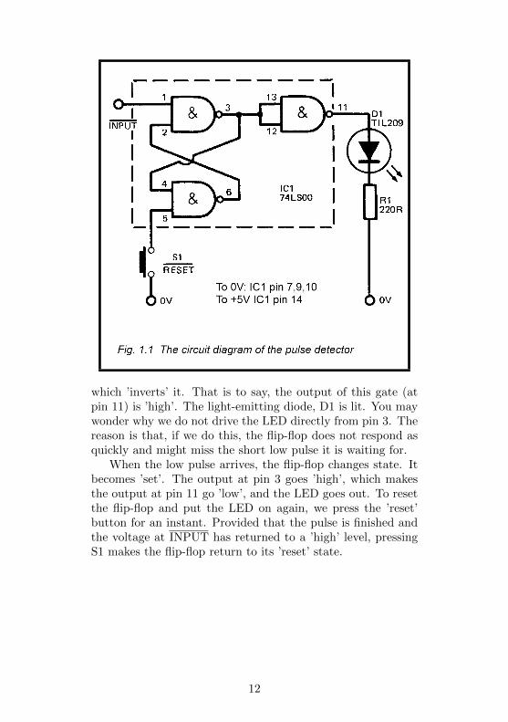
which ’inverts’ it. That is to say, the output of this gate (atpin 11) is ’high’. The light-emitting diode, D1 is lit. You maywonder why we do not drive the LED directly from pin 3. Thereason is that, if we do this, the flip-flop does not respond asquickly and might miss the short low pulse it is waiting for.
When the low pulse arrives, the flip-flop changes state. Itbecomes ’set’. The output at pin 3 goes ’high’, which makesthe output at pin 11 go ’low’, and the LED goes out. To resetthe flip-flop and put the LED on again, we press the ’reset’button for an instant. Provided that the pulse is finished andthe voltage at INPUT has returned to a ’high’ level, pressingS1 makes the flip-flop return to its ’reset’ state.
12
Building it
This project can be built up on any small scrap of strip-board.There is hardly any need to put it in a case but it is easy tofind a small plastic container which will suit the purpose ofenclosing it. The push-button and LED are mounted on thecase.
There is no need for a power supply switch. The best ar-rangement is to have three wires about 20cm long to connectthe Detector to the circuit (or the line of the micro) which isbeing tested. Solder a crocodile clip to the flying end of eachwire. Preferably use clips with insulating plastic covers, andhave clips of three different colours so that you know which iswhich. One of the wires is for connecting the Detector to the0V line of the micro, or test circuit. This wire connects alsothe IC and to the other points shown on Fig.1.1. The secondwire is for taking power from to the +5V rail of the micro,or tested circuit. This wire connects to pin 14 of the IC. Thethird wire is the INPUTwire, going to pin 1.
Using it
Switch off the micro or the circuit you are testing. Clip the Vand +5V leads to the V and +5V rails of the micro or othercircuit. Clip the INPUT wire to the line you want to test forlow pulses. Then switch on the power supply. The LED mayor may not light to begin with, depending on which state theflip-flop goes to when switched on. If the LED does not light,press S1 for an instant. If the LED does not light then, it maybe that the tested line is not actually ’high’, or that a seriesof ’low’ pulses are coming along it so often that the flip-flopbecomes ’set’ almost immediately after you reset it. If this isthe case, there is nothing more you can do, for the detector isnot designed to work with a rapid series of ’low’ pulses.
If the LED comes on and stays on when you press S1, op-erate the micro or test circuit in the way which you believe isgoing to produce that single ’low’ pulse. If or when the pulsearrives, the LED goes out.
13
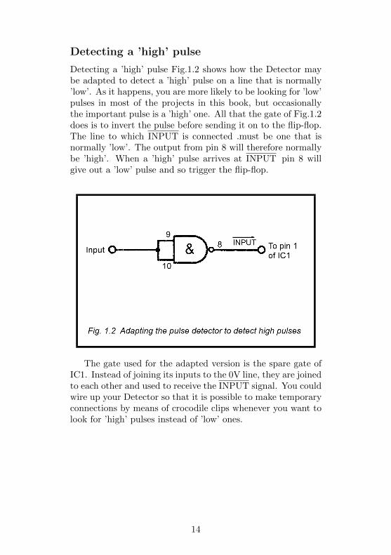
Detecting a ’high’ pulse
Detecting a ’high’ pulse Fig.1.2 shows how the Detector maybe adapted to detect a ’high’ pulse on a line that is normally’low’. As it happens, you are more likely to be looking for ’low’pulses in most of the projects in this book, but occasionallythe important pulse is a ’high’ one. All that the gate of Fig.1.2does is to invert the pulse before sending it on to the flip-flop.The line to which INPUT is connected .must be one that isnormally ’low’. The output from pin 8 will therefore normallybe ’high’. When a ’high’ pulse arrives at INPUT pin 8 willgive out a ’low’ pulse and so trigger the flip-flop.
The gate used for the adapted version is the spare gate ofIC1. Instead of joining its inputs to the 0V line, they are joinedto each other and used to receive the INPUT signal. You couldwire up your Detector so that it is possible to make temporaryconnections by means of crocodile clips whenever you want tolook for ’high’ pulses instead of ’low’ ones.
14

PARTS REQUIRED for the PULSE DETECTOR
ResistorsR1 220R carbon, 0.25W, 5% tolerance
SemiconductorD1 TI L209 or similar light-emitting diode
Integrated CircuitIC1 74LS00 quadruple 2-input NAND gate
MiscellaneousS1 Push-to-make push-button switchScrap of stripboard (2.5mm matrix)1mm terminal pins (5 off)
Crocodile clips,miniature size (3 off, of different colours)(Better still are miniature clip-on probes, such as’E-Z-Hooks’.)
14-pin IC socket (optional, but recommended)Small plastic case (optional)Connecting wire
15
Project 2PICTURE DIGITISER
Using this device, you can scan a photograph or drawing andsee it appear on the screen of your micro. The scanner is rathera low resolution one, so it works best when the picture has largebold areas of contrasting shades. Fine detail will be lost but,provided that you choose a suitable subject, it is fascinatingto see the result building up block by block on the screen. Thescanner is moved by hand, so it works fairly slowly and de-pends on you to move it accurately. It clearly demonstratesthe principle behind professionally-made (and highly expen-sive) picture digitising equipment. There is a great amount offun to be had from the simple digitiser.
How it works
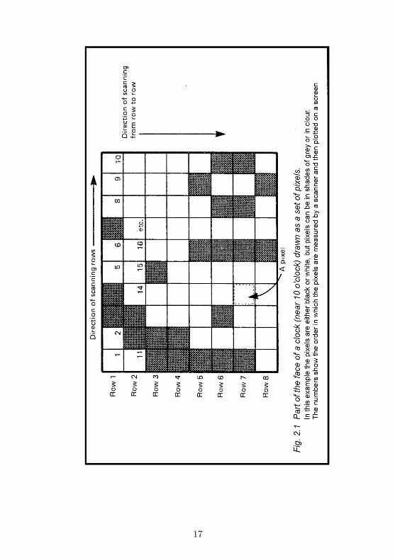
The idea behind this device is that the picture is broken downinto a number of picture elements, or pixels. The picture areaconsists of rows and columns of pixels, as in Fig.2.1. Thescanner moves (or, in this instance, is moved) along each rowof pixels in turn. It measures the brightness of each pixel,and reports this to the micro. Brightness is something whichcould be anything between a brilliant white and the darkestof blacks. There is an unlimited number of shades of grey inbetween. If the picture is a coloured one, the different colourscan be considered to be equivalent to different shades of grey.
The micro can not accept an unlimited number of differentpossible shades. To keep the circuit simple, this scanner isdesigned to recognise only 4 different shades. The lightest iswhite, the darkest is black and there are 2 shades of grey (lightgrey and dark grey or equivalent colours) in between. Whenthe scanner measures the overall brightness of a pixel it tellsthe micro to which of these 4 possible shades the pixel shadeis closest. The micro plots each pixel on the screen as it isreported. It plots small squares which show a correspondingrange of brightness. White is a solid block of light on the
16
17
screen, and black is a blank area of screen. The greys arerepresented by patterns of dots in which light grey has morewhite dots than dark grey.
The way you represent the greys depends on the graphicsprovided by your micro. The ZX81 has only one shade of grey,so both shades of grey have to be plotted the same, though thedark one could be plotted as black and the light one as whiteif this makes the picture better to look at. With the Spectrumyou can define your own patterns with various proportions ofdots, as described later, and possibly use BRIGHT 1 for white.
The circuit (Fig.2.2) relies on a photodiode (D1) to detectthe light reflected from the picture. The light comes froma torch-bulb, which is mounted with the photodiode in thescanner (Fig.2.4). If light is falling on D1, a small leakagecurrent flows through R1 and D1. The more light reaching D1,the larger the current. The larger the current, the greater thepotential difference across R1. The greater the PD, the lowerthe voltage at point A. This is because the voltage at the topend of R1 is fixed at +5V, so any increase in PD across it mustmake the voltage fall at its other end.
The level of voltage at point A is measured by three com-parators (IC1, IC2 and IC3). These each compare the volt-age at their inverting input (-) with the voltage at theirnon-inverting input (+). In this circuit, the inverting inputs areall connected to point A, while the non-inverting inputs areeach connected to the wiper of a variable resistor, (RV1, RV2and RV3). Each resistor is set so that the voltage at its wiperhas a fixed value between 0V and +5V. The setting is differentfor each variable resistor. For each comparator, if the voltageat the inverting input (from A) is higher than the voltage atthe non-inverting input (from the variable resistor), the out-put of the comparator rises sharply toward +5V. If the voltagefrom A is lower than the voltage from the variable resistor, theoutput falls sharply toward 0V.
The variable resistors are set so that when D1 is receivinglight reflected from white paper, the voltage at A is lower thanthe voltage from any of the variable resistors. The outputs ofall three comparators are ’low’. If very little light is reaching
18
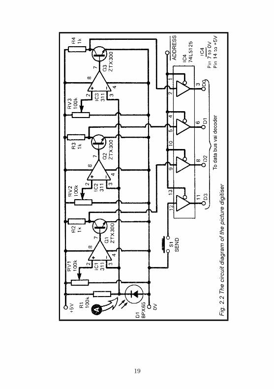
19
D1 (reflection from black paper), the voltage from A is greaterthan any voltage from the resistors, so all outputs are ’high’.In between (shades of grey, or colours), one or more of thecomparators has a ’high’ output and the others have a ’low’output.
The output of each comparator goes to a transistor. Whenthe comparator has a high output, the transistor is switchedfully on. The voltage at its collector falls to 0V (= ’low’).The transistor inverts the output from the comparator. Thisvoltage is fed to a buffer gate in IC4. When the buffer isenabled (see next section) and ’low’ level is sent to the buffer,a ’low’ level is put on to the data bus. Conversely, when thecomparator has a ’low’ output, a ’high’ level appears on thedata bus.
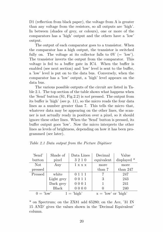
The various possible outputs of the circuit are listed in Ta-ble 2.1. The top section of the table shows what happens whenthe ’Send’ button (S1, Fig.2.2) is not pressed. The output fromits buffer is ’high’ (see p. 11), so the micro reads the four datalines as a number greater than 7. This tells the micro that,whatever data may be appearing on the other lines, the scan-ner is not actually ready in position over a pixel, so it shouldignore these other lines. When the ’Send’ button is pressed, itsbuffer output goes ’low’. Now the micro interprets the otherlines as levels of brightness, depending on how it has been pro-grammed (see later).
Table 2.1 Data output from the Picture Digitiser
’Send’ Shade of Data Lines Decimal Valuebutton pixel 3 2 1 0 equivalent displayed *
Not Any 1 x x x more morepressed than 7 than 247Pressed white 0 1 1 1 7 247
Light grey 0 0 1 1 3 243Dark grey 0 0 0 1 1 241
Black 0 0 0 0 0 240
0 = ’low’ 1 = ’high’ x = ’low’ or ’high’
* on Spectrum; on the ZX81 add 65280; on the Ace, ’31 IN15 AND’ gives the values shown in the ’Decimal Equivalent’column.
20
Addressing
The addressing of this project is not completely provided forby the decoder (p. 158). The data inputs of the decoder areable to receive only one data line from each device (in otherwords, only one bit of data from each address). This projectneeds to be able to send 4 bits of data to the micro. As Fig.2.2shows, it has four data outputs which are connected directlyto lines D0 to D3 of the data bus. The wires from the PictureDigitiser go to 4 terminal pins on the board of the Decoder but,from there, the connection is made directly to the data bus ofthe micro, as shown in Fig.D.1. Single-bit data inputs havecomplete address decoding on the decoder board; decoding oflines A0 to A4 is done by IC1 and IC2, while the decodingof lines A5 to A7 is done (for data inputs) by IC5. We canstill use the decoding done by IC1 and IC2, but the PictureDigitiser needs to have its own IC to take care of decoding A5to A7.
The decoding of lines A0 to A4 gives us a signal whichis called ADDRESS . This goes ’low’ whenever data is to besent to any one of the addresses listed in Table D.2 (p. 173).If you want to have only the Picture Digitiser plugged on tothe micro: and nothing else, there is no need to bother withany further decoding. Simply connect the ADDRESS outputterminal of the decoder (Fig.D.1) to the ADDRESS’ outputterminal of the Picture Digitiser (Fig.2.2). The Digitiser thenhas all 8 of the possible addresses of Table D.2. The microreads the state of the pad, at any one of these addresses.
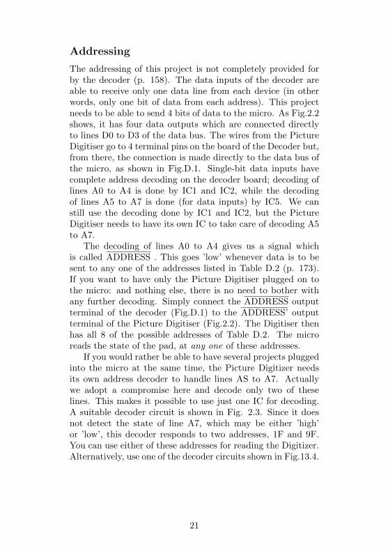
If you would rather be able to have several projects pluggedinto the micro at the same time, the Picture Digitizer needsits own address decoder to handle lines AS to A7. Actuallywe adopt a compromise here and decode only two of theselines. This makes it possible to use just one IC for decoding.A suitable decoder circuit is shown in Fig. 2.3. Since it doesnot detect the state of line A7, which may be either ’high’or ’low’, this decoder responds to two addresses, 1F and 9F.You can use either of these addresses for reading the Digitizer.Alternatively, use one of the decoder circuits shown in Fig.13.4.
21
Building it
The first thing to do is to make the scanner (Fig.2.4). Thereare several ways in which you can construct this, depending onthe materials you have available and your skill at working withthese materials. You may decide to base it on a small metalor plastic box, boring holes and fixing partitions to arrive atthe design shown in the figure. Or you may decide to beginwith a block of wood (or a large cork stopper, which is easierto carve) and drill out the various channels required. Theessential points of the scanner are:
i It rests flat on the pictureii It has an aperture about 5mm square on the lower side;
22
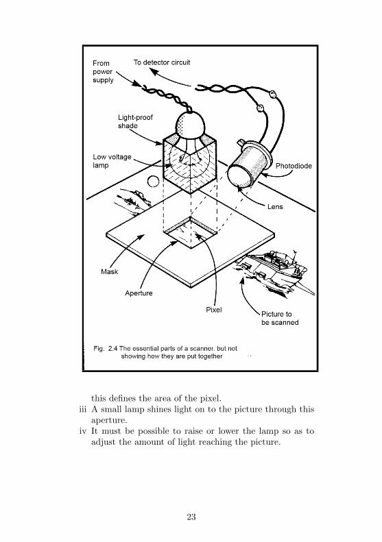
this defines the area of the pixel.iii A small lamp shines light on to the picture through this
aperture.iv It must be possible to raise or lower the lamp so as to
adjust the amount of light reaching the picture.
23
The lamp should be a firm fit in its mounting, so that itdoes not readily slide out of its fixed position.
v The photodiode is to be fixed in position and aimed sothat it catches light reflected from the picture, but doesnot receive light coming directly from the lamp.
vi It is best ,if all surfaces in the scanner are painted mattblack to cut out unwanted reflections of light.
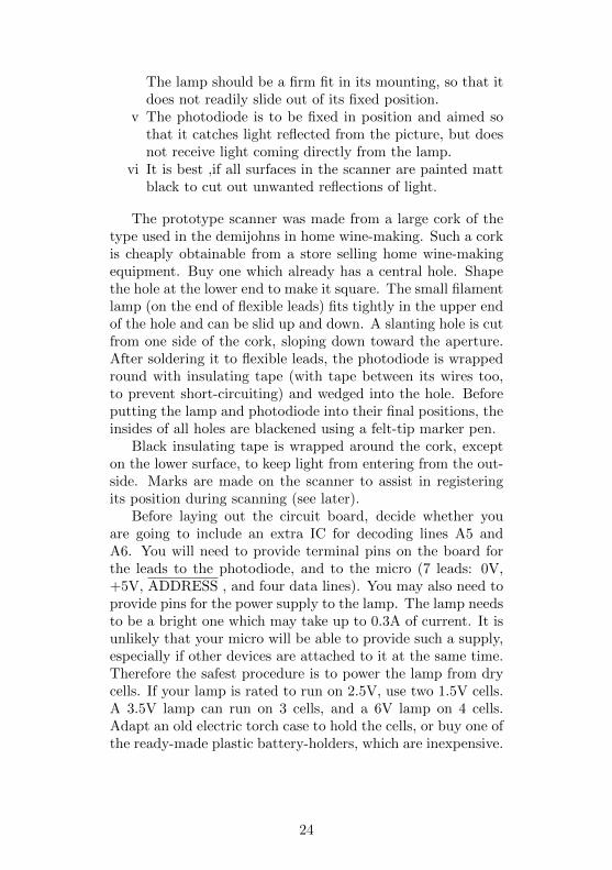
The prototype scanner was made from a large cork of thetype used in the demijohns in home wine-making. Such a corkis cheaply obtainable from a store selling home wine-makingequipment. Buy one which already has a central hole. Shapethe hole at the lower end to make it square. The small filamentlamp (on the end of flexible leads) fits tightly in the upper endof the hole and can be slid up and down. A slanting hole is cutfrom one side of the cork, sloping down toward the aperture.After soldering it to flexible leads, the photodiode is wrappedround with insulating tape (with tape between its wires too,to prevent short-circuiting) and wedged into the hole. Beforeputting the lamp and photodiode into their final positions, theinsides of all holes are blackened using a felt-tip marker pen.
Black insulating tape is wrapped around the cork, excepton the lower surface, to keep light from entering from the out-side. Marks are made on the scanner to assist in registeringits position during scanning (see later).
Before laying out the circuit board, decide whether youare going to include an extra IC for decoding lines A5 andA6. You will need to provide terminal pins on the board forthe leads to the photodiode, and to the micro (7 leads: 0V,+5V, ADDRESS , and four data lines). You may also need toprovide pins for the power supply to the lamp. The lamp needsto be a bright one which may take up to 0.3A of current. It isunlikely that your micro will be able to provide such a supply,especially if other devices are attached to it at the same time.Therefore the safest procedure is to power the lamp from drycells. If your lamp is rated to run on 2.5V, use two 1.5V cells.A 3.5V lamp can run on 3 cells, and a 6V lamp on 4 cells.Adapt an old electric torch case to hold the cells, or buy one ofthe ready-made plastic battery-holders, which are inexpensive.
24
25
The power supply to the battery is then completely sepa-rate from the main circuit of the Digitiser.
Wire up R1 and D1 first, and one of the comparators (sayIC1 with RV1). Test the circuit with a voltmeter connected topoint A. In fairly low room lighting the voltage at A is close to+5V but, when D1 is moved toward the lamp (switched on),the voltage drops almost to 0V. If you fail to obtain a changingvoltage, is it possible that you have connected D1 the wrongway round. Set RV1 to about the middle of its track; thevoltage at its wiper and at pin 2 of IC1 is then about 2.5V.Move D1 toward the lamp, the output of IC1 (pin 7) is close to+5V at first but suddenly swings to 0V when D1 is put closerto the lamp. Now wire up R2 and 01. Check that the voltageat the collector of Q1 (i.e. where Q1 is linked to R2) changesfrom 0V to +5V as D1 is moved toward a lamp.
Repeat the above sequence of tests on the other two com-parators as you assemble these sections of the circuit.
Next wire up the buffer (IC4). Temporarily connect theADDRESS’ input to the 0V line, to enable the buffers. Youcan then check that the outputs change as expected when D1is moved toward the lamp (see Table 2.1). Adjust the settingsof RV1, RV2 and RV3 so that the outputs change in order asD1 is moved toward and away from the lamp.
Finally, wire up the address decoder as in Fig.2.3, and con-nect its output to the ADDRESS’ input of IC4.
Final check
Before connecting the circuit to the micro it is important totest it thoroughly. Use a multimeter or a circuit-tester to checkthat there are no short-circuits between next-door data lines,or between data lines and the power lines. It is easy for athin thread of solder to form a bridge between such lines. Alsocheck that there is no short-circuit between the +5V powerline and the 0V line. It is also worth testing each data line andother control line to make sure that there really is a connectionbetween the plug at one end of the line and the IC or othercomponent which is at the other. A ’dry joint’ which causes abreak in a line can cause all kinds of problems
26
in getting the circuit to work.If it passes the tests above, the Digitiser should now be
ready to plug into the Decoder, which itself is plugged into themicro. Switch on the power supply to the micro. If the displayon the screen is not as expected, switch off immediately andrepeat the checks.
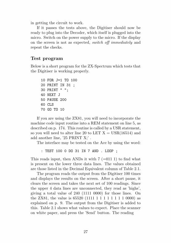
Test program
Below is a short program for the ZX-Spectrum which tests thatthe Digitiser is working properly.
10 FOR J=1 TO 100
20 PRINT IN 31 ;
30 PRINT " ";
40 NEXT J
50 PAUSE 200
60 CLS
70 GO TO 10
If you are using the ZX81, you will need to incorporate themachine code input routine into a REM statement on line 5, asdescribed on p. 174. This routine is called by a USR statement,so you will need to alter line 20 to LET X = USR(16514) andadd another line, ’25 PRINT X;’ .
The interface may be tested on the Ace by using the word:
: TEST 100 0 DO 31 IN 7 AND . LOOP ;
This reads input, then ANDs it with 7 (=011 1) to find whatis present on the lower three data lines. The values obtainedare those listed in the Decimal Equivalent column of Table 2.1.
The program reads the output from the Digitiser 100 timesand displays the results on the screen. After a short pause, itclears the screen and takes the next set of 100 readings. Sincethe upper 4 data lines are unconnected, they read as ’highs’,giving a total value of 240 (1111 0000) for those lines. Onthe ZX81, the value is 65520 (1111 1 1 1 1 1 1 1 1 0000) asexplained on p. 9. The output from the Digitiser is added tothis. Table 2.1 shows what values to expect. Place the scanneron white paper, and press the ’Send’ button. The reading
27

should be ’247’ (65527 on the ZX81). Try it on black paperalso and on various shades of grey. You can adjust the variableresistors slightly so that the readings change at the levels ofgrey which you decide on.
The only possible readings when the button is pressed are240, 241, 243 and 247 (or their equivalent on the ZX81), de-pending on the brightness of the pixel. When the button isnot pressed, you will get 248, 249, 251 and 255. If you obtainother readings, there is something wrong. Maybe the addressdecoder is not working properly. This is likely if you get thesame result (especially ’255’) every time, no matter what thebrightness of light or whether or not you press S1. You cancheck the address decoder by using the Pulse Detector (Project). Connect its input to the ADDRESS output of the Decoder,or to the ADDRESS’ output of IC5 (Fig.2.3). Reset it, thenrun the test program. The LED should go off when the pro-gram is run. If it does not, check the decoding circuits.
Assuming the address is being decoded properly, but youare still getting unexpected numbers, write down the numbersyou get in binary form, and also write down, in binary, thenumbers you expect to get. By comparing these you may findthat one of the data lines is ’stuck’, always giving ’high’ or’low’ when it should be changing. If so, examine the wiring ofthis line, looking for short circuits to next-door data lines orto the power lines. Look also for gaps and breaks in the line,dry solder joints and other possible bad connections.
The logic circuits are not ’tricky’ in the sense that they needcareful adjustment to get them to work. If you obtain your IC’snew from well-known suppliers, they are very unlikely to befaulty, so if the circuit does not give the expected results, it isnearly always a fault in the construction.
Programming
The program listed below shows how the Spectrum is used toread data from the scanner and plot it on the screen.
10 LET J=0 : BRIGHT 0 : CLS
20 LET scan=IN 31
28
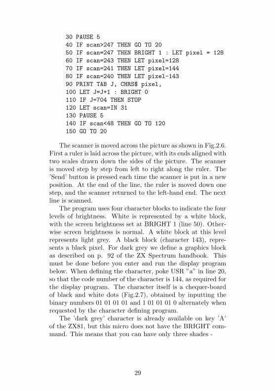
30 PAUSE 5
40 IF scan>247 THEN GO TO 20
50 IF scan=247 THEN BRIGHT 1 : LET pixel = 128
60 IF scan=243 THEN LET pixel=128
70 IF scan=241 THEN LET pixel=144
80 IF scan=240 THEN LET pixel-143
90 PRINT TAB J, CHRS$ pixel,
100 LET J=J+1 : BRIGHT 0
110 IF J=704 THEN STOP
120 LET scan=IN 31
130 PAUSE 5
140 IF scan<48 THEN GO TO 120
150 GO TO 20
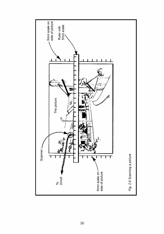
The scanner is moved across the picture as shown in Fig.2.6.First a ruler is laid across the picture, with its ends aligned withtwo scales drawn down the sides of the picture. The scanneris moved step by step from left to right along the ruler. The’Send’ button is pressed each time the scanner is put in a newposition. At the end of the line, the ruler is moved down onestep, and the scanner returned to the left-hand end. The nextline is scanned.
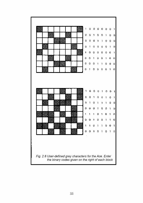
The program uses four character blocks to indicate the fourlevels of brightness. White is represented by a white block,with the screen brightness set at BRIGHT 1 (line 50). Other-wise screen brightness is normal. A white block at this levelrepresents light grey. A black block (character 143), repre-sents a black pixel. For dark grey we define a graphics blockas described on p. 92 of the ZX Spectrum handbook. Thismust be done before you enter and run the display programbelow. When defining the character, poke USR ”a” in line 20,so that the code number of the character is 144, as required forthe display program. The character itself is a chequer-boardof black and white dots (Fig.2.7), obtained by inputting thebinary numbers 01 01 01 01 and 1 01 01 01 0 alternately whenrequested by the character defining program.
The ’dark grey’ character is already available on key ’A’of the ZX81, but this micro does not have the BRIGHT com-mand. This means that you can have only three shades -
29
30
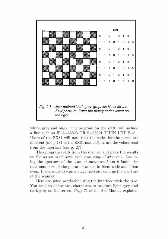
white, grey and black. The program for the ZX81 will includea line such as IF S=65523 OR S=65521 THEN LET P=8 .Users of the ZX81 will note that the codes for the pixels aredifferent (see p.181 of the ZX81 manual), as are the values readfrom the interface (see p. 27).
This program reads from the scanner and plots the resultson the screen in 22 rows, each consisting of 32 pixels. Assum-ing the aperture of the scanner measures 5mm x 5mm, themaximum size of the picture scanned is 16cm wide and 11cmdeep. If you want to scan a bigger picture, enlarge the apertureof the scanner.
Here are some words for using the interface with the Ace.You need to define two characters to produce light grey anddark grey on the screen. Page 71 of the Ace Manual explains
31
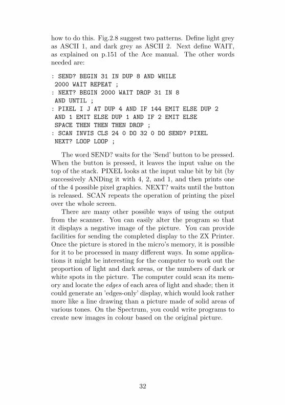
how to do this. Fig.2.8 suggest two patterns. Define light greyas ASCII 1, and dark grey as ASCII 2. Next define WAIT,as explained on p.151 of the Ace manual. The other wordsneeded are:
: SEND? BEGIN 31 IN DUP 8 AND WHILE
2000 WAIT REPEAT ;
: NEXT? BEGIN 2000 WAIT DROP 31 IN 8
AND UNTIL ;
: PIXEL I J AT DUP 4 AND IF 144 EMIT ELSE DUP 2
AND 1 EMIT ELSE DUP 1 AND IF 2 EMIT ELSE
SPACE THEN THEN THEN DROP ;
: SCAN INVIS CLS 24 0 DO 32 0 DO SEND? PIXEL
NEXT? LOOP LOOP ;
The word SEND? waits for the ’Send’ button to be pressed.When the button is pressed, it leaves the input value on thetop of the stack. PIXEL looks at the input value bit by bit (bysuccessively ANDing it with 4, 2, and 1, and then prints oneof the 4 possible pixel graphics. NEXT? waits until the buttonis released. SCAN repeats the operation of printing the pixelover the whole screen.
There are many other possible ways of using the outputfrom the scanner. You can easily alter the program so thatit displays a negative image of the picture. You can providefacilities for sending the completed display to the ZX Printer.Once the picture is stored in the micro’s memory, it is possiblefor it to be processed in many different ways. In some applica-tions it might be interesting for the computer to work out theproportion of light and dark areas, or the numbers of dark orwhite spots in the picture. The computer could scan its mem-ory and locate the edges of each area of light and shade; then itcould generate an ’edges-only’ display, which would look rathermore like a line drawing than a picture made of solid areas ofvarious tones. On the Spectrum, you could write programs tocreate new images in colour based on the original picture.
32
33

PARTS REQUIRED for the PICTURE DIGITISER
Resistors (carbon, 0.25W, 5% tolerance)R1 100kR2R4 1k (3 off)
Variable ResistorsRV1RV3 100k miniature horizontal preset (3 off)
SemiconductorsD1 BPX65 or similar photodiodeQ1-03 ZTX300 or similar general-purpose npntransistors (3 off)
Integrated CircuitsIC1-1C3 311 comparator (3 off)IC4 74LS125 quad bus buffer gate with three-state outputIC5 74LS27 triple 3-input NOR gate(optional, if required for decoding)
MiscellaneousS1 Push-to-make push-button switchCircuit board8-pin IC sockets (3 off)14-pin IC sockets (1 or 2 off)10-way socket to fit 10-way plug of decoder board
Lamp for scanner, low voltage (2.5V to 6V), 0.3A (thetype which has a lens moulded into the end of the glassbulb is strongly recommended, as it focusses a bright spotof light on to the paper; available from most stores whichsell electric torches.)
Socket for lampMaterials for making scannerConnecting wire, including thin flexible wire forconnections to scanner
34
Project 3FIVE-KEY PAD
Although it is usual to control the movement of the cursor,or to aim and fire your space-gun against the aliens, by usingthe keys of the regular keyboard of the micro, it is very usefulto have a separate keyboard specially designed for this purpose.This keyboard has 5 keys, which you may use in lots of differentways.
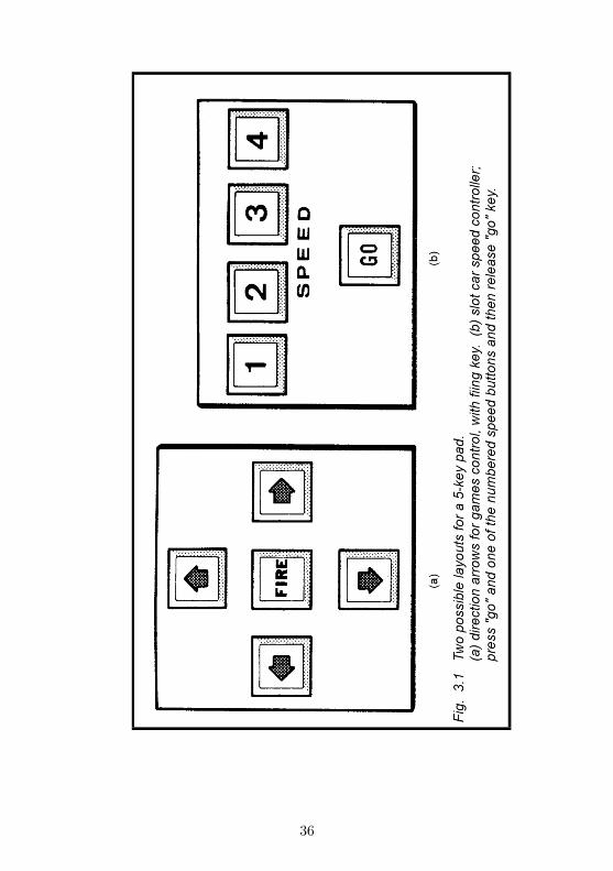
For instance, mark four of them with arrows pointing updown, left and right, and use them for steering the cursor oranything else around the screen. The keys are arranged as inFig.3.1 so that it is easy to remember which is which and tofind the right key quickly. Another way of marking the fourkeys would be according to the point of the compass N, S, Eand W.
The fifth key is a control key which has several possiblefunctions, depending on how you program the micro. In agames program you can use it to fire the space-gun, or perhapsto indicate ”no move”. In a program which draws pictures onthe screen, under the control of the four ”arrow” keys the fifthkey can be used to indicate ”pen down” (move the cursor toa different position and draw a line as it moves) or ”pen up”(move the cursor to a different position, but do not draw aline).
The keyboard can also be used as a special-purpose con-troller for a model railway system or for slot-cars (see Project4), with the keys being marked ’Go’, ’Faster’, ’Slower’, and’Reverse’ (for locos at least!). The fifth key can be ’Emer-gency Stop’. A second keyboard can be used for controllingpoints or signal lamps.
Many two-player games are improved if each player has anindividual keyboard. They are especially useful if it is the sortof game in which each player has to ’make a move’ withoutletting the other player know which move is being made. Also,the computer can be programmed to read one keyboard or theother, depending on whose turn it is to play. Playing out of
35
36
turn is prevented. The keyboard can be used as a remote-operating keyboard. You place the micro in one room andthe keyboard in an adjacent room, sending instructions to themicro along a 6-wire cable.
How it works
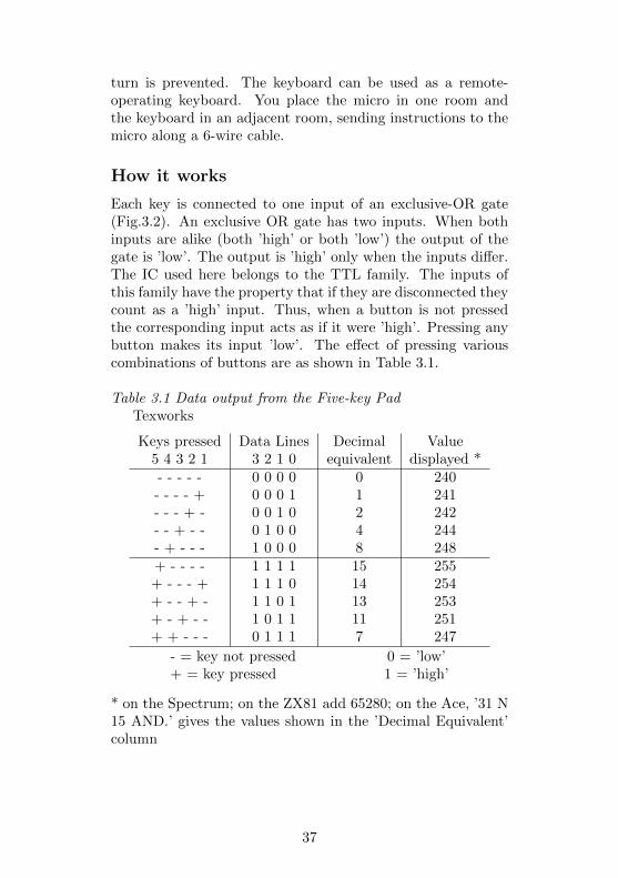
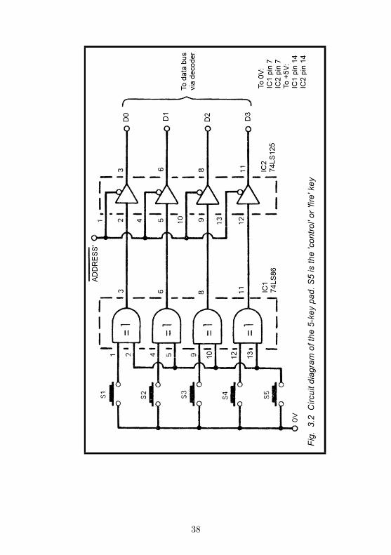
Each key is connected to one input of an exclusive-OR gate(Fig.3.2). An exclusive OR gate has two inputs. When bothinputs are alike (both ’high’ or both ’low’) the output of thegate is ’low’. The output is ’high’ only when the inputs differ.The IC used here belongs to the TTL family. The inputs ofthis family have the property that if they are disconnected theycount as a ’high’ input. Thus, when a button is not pressedthe corresponding input acts as if it were ’high’. Pressing anybutton makes its input ’low’. The effect of pressing variouscombinations of buttons are as shown in Table 3.1.
Table 3.1 Data output from the Five-key PadTexworks
Keys pressed Data Lines Decimal Value5 4 3 2 1 3 2 1 0 equivalent displayed *- - - - - 0 0 0 0 0 240- - - - + 0 0 0 1 1 241- - - + - 0 0 1 0 2 242- - + - - 0 1 0 0 4 244- + - - - 1 0 0 0 8 248+ - - - - 1 1 1 1 15 255+ - - - + 1 1 1 0 14 254+ - - + - 1 1 0 1 13 253+ - + - - 1 0 1 1 11 251+ + - - - 0 1 1 1 7 247
- = key not pressed 0 = ’low’+ = key pressed 1 = ’high’
* on the Spectrum; on the ZX81 add 65280; on the Ace, ’31 N15 AND.’ gives the values shown in the ’Decimal Equivalent’column
37
38

The output of each exlusive-OR gate goes to a buffer withthree-state outputs (see p. 160). The outputs of these buffersare connected to data lines D0 to D3. The buffers are made toput data on the bus by bringing the enable line low. This isconnected to an Addressed Output of the decoder (see Fig.D.1).When one of the addresses of the decoder is read from, thecorresponding Addressed Output goes low. This enables thebuffer, and the data from the buffers is put on to the data bus.
Addressing
As explained for Project 2 (p. 21), the addressing of thisproject is not completely provided for by the decoder (p. 158).If you want to connect only this project to the micro, you cando as suggested on p. 21: wire the ADDRESS output terminalof the decoder (Fig. D.1) to the ADDRESS’ input terminal ofthe 5-Key-Pad (Fig. 3.2(. It can then be addressed using anyone of the addresses in Table D.2.
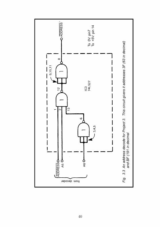
If you would like to have other projects connected at thesame time as this project, you need to add a decoder to thisproject. To keep the wiring as simple as possible, the decoderuses only lines A5 and A6 (Fig. 3.3). As explained on p. 21it responds to two addresses, which are 3F and BF in thisinstance.
If you are building a second pad, it must have a differentaddress. Use the same decoder circuit as in Project 2 (Fig.2.3), which has addresses 1F and 9F. If you do this, you willnot be able to have the Picture Digitiser and the second 5-KeyPad plugged on the micro at the same time. Other decodingcircuits you could use are given in Fig. 13.4 (p. 120).
Building it
Although it is possible to use any kind of switch for the keys,it is best to employ the type specially designed as keyboardkeys. Usually the switch is sold separately from the key-top.Keytops fit on to the switch and are of various types. Somemakes of key have tops in a range of bright colours. Others
39
40
have white tops with transparent covers. You write a letteror symbol on the top (or use rub-down lettering) then clip thetransparent cover over the top to protect the lettering fromwear. Alternatively, draw the symbol or letter on a smallsquare of card and insert this before clipping on the cover.
The project is best mounted in a small plastic case. Casescan be obtained with a sloping top which makes them very suit-able for use as a keyboard enclosure. Alternatively, a plasticbox used for packing foods and other commodities is generallyobtainable free and may be used for housing this project.
The layout and construction of the circuit presents no prob-lems. The two ICs and the decoder IC can easily be accom-modated on a small piece of strip-board which will fit into thecase. Cut an aperture in the lid for the keys. There are nineleads between the pad and the decoder – 3 for addressing, 4 fordata and 2 for power. These can be a metre or so in length toallow you to operate the pad in any convenient position. Theleads end in a 10-way plug which fits the 10-way plug of theDecoder board.
Testing
When construction is complete, test the circuit to make surethat there are no short-circuits between next-door data lines oraddress lines, or between these lines and the power lines. Alsomake sure that there is no short-circuit between the two powerlines, 0V and +5V. Connect the circuit to a 5V power supplyand temporarily connect the address inputs (ADDRESS’ andD5/D6 if used) to the 0V line. Then press each button in turn,while measuring the output from the corresponding buffer witha voltmeter. Table 3.1 shows what to expect.
The pad may now be plugged on to the decoder which isplugged in to the micro. Switch on the micro. If the usualdisplay fails to appear on the screen, switch off immediatelyand repeat your checking of the circuit. Now run a simple testprogram. A program suitable for the Spectrum is given on p.27, but change the address on line 20 to 63. Below is a similarprogram for use with the ZX81.
41
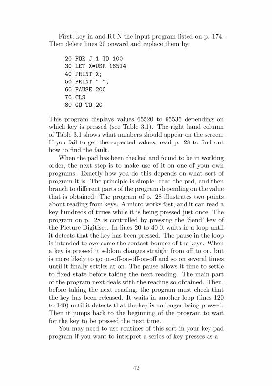
First, key in and RUN the input program listed on p. 174.Then delete lines 20 onward and replace them by:
20 FOR J=1 TO 100
30 LET X=USR 16514
40 PRINT X;
50 PRINT " ";
60 PAUSE 200
70 CLS
80 GO TO 20
This program displays values 65520 to 65535 depending onwhich key is pressed (see Table 3.1). The right hand columnof Table 3.1 shows what numbers should appear on the screen.If you fail to get the expected values, read p. 28 to find outhow to find the fault.
When the pad has been checked and found to be in workingorder, the next step is to make use of it on one of your ownprograms. Exactly how you do this depends on what sort ofprogram it is. The principle is simple: read the pad, and thenbranch to different parts of the program depending on the valuethat is obtained. The program of p. 28 illustrates two pointsabout reading from keys. A micro works fast, and it can read akey hundreds of times while it is being pressed just once! Theprogram on p. 28 is controlled by pressing the ’Send’ key ofthe Picture Digitiser. In lines 20 to 40 it waits in a loop untilit detects that the key has been pressed. The pause in the loopis intended to overcome the contact-bounce of the keys. Whena key is pressed it seldom changes straight from off to on, butis more likely to go on-off-on-off-on-off and so on several timesuntil it finally settles at on. The pause allows it time to settleto fixed state before taking the next reading. The main partof the program next deals with the reading so obtained. Then,before taking the next reading, the program must check thatthe key has been released. It waits in another loop (lines 120to 140) until it detects that the key is no longer being pressed.Then it jumps back to the beginning of the program to waitfor the key to be pressed the next time.
You may need to use routines of this sort in your key-padprogram if you want to interpret a series of key-presses as a
42

series of commands. Of course, if the keys are simply to bepressed and held down for as long as a particular action is tocontinue, you simply read the pad repeatedly, without pauses,until a change of input occurs.
PARTS REQUIRED for the FIVE-KEY PAD
Integrated CircuitsIC1 74LS86 quad exclusive-OR gateIC2 74LS125 quad bus buffer gate with three-state outputIC3 74LS27 triple 3-input NOR gate (optional, if lines A5and A6 are to be decoded)
MiscellaneousS1S5 Key-switches with tops (5 off)14-pin IC sockets (2 or 3 off)10-way socket to fit 10-way plug of decoder boardKey-pad caseConnecting wire
43
Project 4MODEL CONTROLLER
Putting a micro in command of model railway system addsgreatly to the realism of its operation. The locomotive can bestopped, started, or reversed and its speed can be varied ina number of stages. The project can also be used with otherelectrically powered models such as slot-cars. If you are keenon building your own robot, this project. provides a way tocontrol its actions. In fact, any model which is driven by low-voltage DC motors, or is activated by electromagnets can becontrolled through this interface. On the model railway scene,it may be used for switching points. The interface can alsoswitch lamps, so is ideal for signal-switching.
Many of the circuits used for controlling the speed of a mo-tor require that the power source should have a higher outputvoltage than is actually needed for driving the motor at topspeed. This circuit employs relays to do the switching, so itis able to take power from the transformer or power pack thatyou normally use for your model railways or slot-cars. There isno need to obtain or build a special power supply. The relaysdo not cause loss of voltage, so the motors run at top speedwhen you want them to do so.
The project as described here is suitable for use with amodel railway but you will find it easy to adapt it to slot-carsor other models. One point about the circuit is that you do notneed to build it all at once. You can start with just one relayand expand it with further relays from time to time. As yourmodel railway system grows, you can build a second or even athird version of the project, perhaps using one for controllingthe locomotive and the other for controlling points and signallamps.
How it works
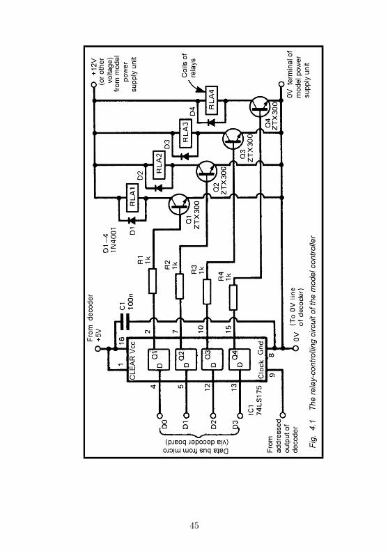
Fig.4.1 shows the relay-control side of the project. IC1 containsfour latches. The D (for data) inputs of these are con-
44
45
nected to 4 lines of the data bus. The IC also has a ’clock’ in-put (pin 9). This is connected to one of the Addressed Outputsof the decoder (Fig.D.1). When the micro wants to send datato the Controller, it puts data on the data bus and the Con-troller’s address on the address bus. The address is decodedcompletely by the decoder, with the result that the correspond-ing Addressed Output goes low for an instant. This low pulsetriggers the latches of ICI. The output (Q) of each latch be-comes the same as its data input (D). Once the triggering pulseis over, Q does not change even though D changes. In fact, Dchanges immediately the trigger pulse is over, for the micro isbusily sending data to its memory, to the printer or other de-vices, or is receiving data. But the data which was on the busat the instant the triggering pulse occurred is held unchanged(latched) until the next time that the micro sends data to theController.
The output of each latch supplies base current to a tran-sistor. If Q is ’low’, there is no base current. If 0 is ’high’,base current flows and the transistor is turned on. This causesa collector current to flow, which activates the coil of a relay.What happens then depends on how the relay is wired.
Fig.4.2 shows a typical relay circuit for controlling a modellocomotive. Note that the power supply for the relay coils andfor the locomotive all come from the power supply unit whichbelongs to the model railway. This must be a DC supply andyou must not use the circuit with voltages higher than 25V,for this would damage the transistors. The normal voltage formodels is 12V or less, so this circuit is very likely to be suitablefor all your models.
Relay 3 (RLA3) is a simple on-off switch. It is wired so thatthe circuit is closed (the loco moves) when the output of thelatch is ’high’ and the transistor is turned on. The current tothe track may pass through two resistors (R5,R6), but eitheror both of these may be short-circuited by closing relays 1 and2. These are wired so that they are open when the output oftheir latches is ’low’.
When relays 1 and 2 are both open, the current to thetrack has to pass through R5 and R6, putting a resistance of16.8ohms in series with the motor of the locomotive. This
46
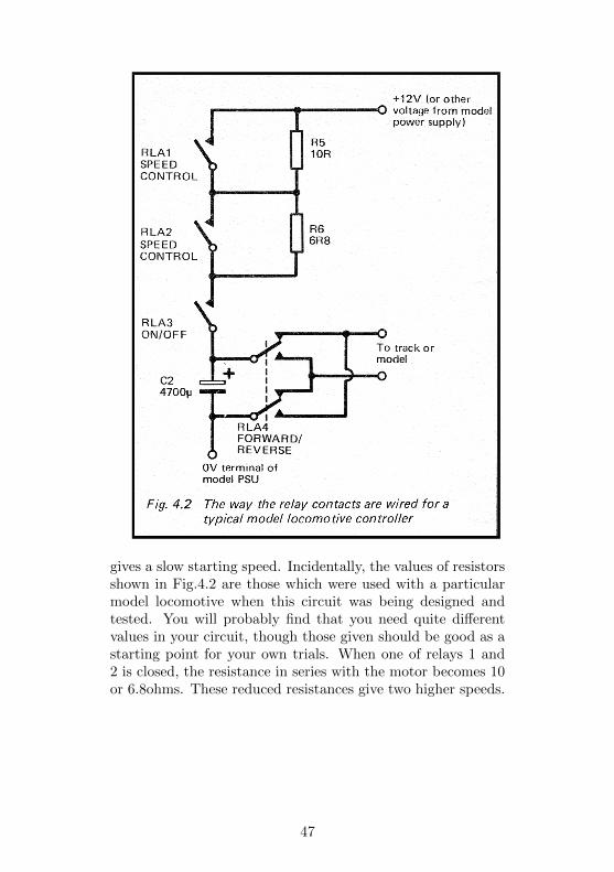
gives a slow starting speed. Incidentally, the values of resistorsshown in Fig.4.2 are those which were used with a particularmodel locomotive when this circuit was being designed andtested. You will probably find that you need quite differentvalues in your circuit, though those given should be good as astarting point for your own trials. When one of relays 1 and2 is closed, the resistance in series with the motor becomes 10or 6.8ohms. These reduced resistances give two higher speeds.
47
Finally, both relays may be closed, reducing the resistance tozero and putting the locomotive into top speed.
Relay 4 is a reversing relay. The relay has two pairs ofcontacts which are changed over simultaneously. As a result,the current flows one way or the other around the circuit andthe loco runs forward or in reverse.
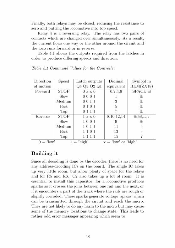
Table 4.1 shows the outputs required from the latches inorder to produce differing speeds and direction.
Table 4.1 Command Values for the Controller
Direction Speed Latch outputs Decimal Symbol inof motion Q4 Q3 Q2 Q1 equivalent REM(ZX18)Forward STOP 0 x x 0 0,2,4,6 SPACE �
Slow 0 0 0 1 1 �Medium 0 0 1 1 3 �
Fast 0 1 0 1 5 �Top 0 1 1 1 7 �
Reverse STOP 1 x x 0 8,10,12,14 �,�,£, :Slow 1 0 0 1 9 �
Medium 1 0 1 1 11 ”Fast 1 1 0 1 13 $
Top 1 1 1 1 15 ?
0 = ’low’ 1 = ’high’ x = ’low’ or ’high’
Building it
Since all decoding is done by the decoder, there is no need forany address-decoding ICs on the board. The single IC takesup very little room, but allow plenty of space for the relaysand for R5 and R6. C2 also takes up a lot of room. It isessential to install this capacitor, for a locomotive producessparks as it crosses the joins between one rail and the next, orif it encounters a part of the track where the rails are rough orslightly corroded. These sparks generate voltage ’spikes’ whichcan be transmitted through the circuit and reach the micro.They are not likely to do any harm to the micro but may causesome of the memory locations to change state. This leads torather odd error messages appearing which seem to
48
bear no relation to the program. If interference is worse theprogram may ”crash”. This capacitor completely eliminatedall such interference in the prototype circuit. C2 should bewired as close as possible to the two terminals which supplypower to the track. If a reversing relay is fitted, C2 must beas close as possible to this, on the side nearer the other relays(see Fig.4.2).
There are similar reasons for C1. Latches have the habit ofbecoming ’unlatched’ if there is interference around. They aresensitive even to the voltage surges caused by switching therelays on and off. Position C1 so that its wires are soldered asclose as possible to the power terminals of IC1 (pins 8 and 16).
The final protective feature is the diodes. When relaysswitch off, a large reverse current is generated. This couldeventually damage the transistors. The diodes conduct thiscurrent safely away to the +5V line. The diodes should bewired as close as possible to the terminals of the coils of therelays.
The controller is connected to the decoder board at 2 points.One connection is to the data lines; this cable requires 4 wiresand may be plugged on to one of the 10-way plugs. The otherconnection is to one of the 3-way plugs with an AddressedOutput; this needs 3 wires, one for the Addressed Output, theothers being the 0V and +5V lines.
As mentioned earlier, there is no need to build the wholecircuit at once. If you want to try it out on a small scalefirst, wire up just IC1, R1, 01, D1, and RLA1. You also needto include C1 and C2. This will allow you to experiment withcontrolling- one relay which you might use, for example, simplyto start and stop the locomotive. Speed control and reversingcan be added later. At that stage you may decide to use onlyone relay for speed control (giving just 3 speeds slow, medium,top-speed), so freeing a relay for use in switching points or op-erating signal lamps. The main point is that, if you start witha small system, build it on a board large enough to accommo-date future expansion.
As mentioned above, the most suitable values for R5 andR6 depend on the characteristics of the motor of the locomotiveor other model. The best course is to try connecting
49
the resistors in series with the locomotive before wiring thempermanently into the circuit. The amount of current takenby the motor inlay be 1 ampere or more, so it is essential touse resistors rated at 2.5W at least. Fixed-value wire-woundresistors are available cheaply. It is possible to obtain vari-able wire-wound resistors (3 watts), but these are relativelyexpensive so the best course is to buy a selection of fixed-valueresistors and experiment with these. If you are following thetwo-relay/two-resistor scheme of Fig.4.2, first find out what re-sistance is enough to let the locomotive run at its lowest steadyspeed. The speed must be such that the motor does not stallwhen the loco crosses a gap in the track or when running roundsharp bends. Also it must allow a stationary locomotive to be-gin moving while pulling the heaviest train it is likely to haveto pull. Having established the correct value (which is the to-tal value of R5 and R6), divide this value into two parts, onerather larger than the other. In Fig.4.2, the total value is 16R8ohms, broken into 1 OR and 6R8 ohms. These values are, ofcourse, the nearest standard values obtainable. If you need avalue which is non-standard, it is often possible to join twoor more resistors in series; for example, you can make up aresistance of 7R5 by joining 1 R, 1R, 2R2 and 3R3 ohms inseries. Often an easier method is to put two larger resistors inparallel. In this instance, wire two 15R resistors in parallel toobtain 7R5 ohms. When wired in parallel, and providing theresistors are more-or-less equal in value, they share the cur-rent. Resistors of lower rating may be used, such as 1W or 2Wcarbon resistors.
Before connecting the controller to the micro, test it tomake sure that there are no short-circuits between adjacentdata lines, between the data lines and the power lines, andbetween the two power lines. The model’s +12V (or other)power line does not connect directly to any line going to andfrom the micro, but its 0V line must be connected to 0V lineof the project. To test the operation of the circuit, connect thecontroller to the track, and to the power lines of the decoder(plugged into the micro), but do not connect the data lines orthe Addressed Output line yet. Use leads with crocodile clipsto connect the data line terminals and Addressed Output
50
terminal of the controller to the 0V line.Switch on the power supply to the controller and the rail-
way power supply unit. Connect the lead of terminal D0 tothe +5V line. Then connect the Addressed Output lead (i.e.the one which connects to the ’clock’ terminal of IC1) to the+5V line. As soon as it makes contact with the +5V line, theoutput of latch 1 changes from ’low’ to ’high’, because of the’high’ level on its input. Often it changes before you actuallytouch the lead against the +5V line, for the slight rise in volt-age caused by taking it away from the 0V line is enough totrigger the latches. Putting the lead back on to the 0V linehas no further effect. As the output of latch 1 goes ’high’, thelocomotive should start moving slowly. Now put the D0 leadback to the 0V line, touch the Addressed Output (’clock’) leadto the +5V line and the locomotive stops. This is because theoutput from latch 1 has now returned to ’low’. In a similarway check the action of the other latches and relays.
Programming
Programming the controller to perform a required action isextremely easy. Just use the OUT command on the ZXSpec-trum or Ace, or the equivalent machine-code subroutine on theZX81 (p. 174), with one of the values of Table 4.1.
There is one point to be considered when starting the loco-motive (or other motor) from rest. Some model power supplyunits have an automatic cut-out which shuts down the supplyif it becomes overloaded. If you try to accelerate the locomo-tive too rapidly by starting it off at top speed (Relays 1, 2 and3 on together), the sudden surge of current may trip the cut-out. You will then have to reset the power unit by hand. Ifyour unit is of this type, always start off the locomotive at itsslowest speed. Once it has started moving, it can be put intohigher speeds almost immediately without risk of triggeringthe cut-out.
On the other hand, certain types of motor need an initialburst of power to get them running, after which they can be runat relatively tow speed. Slot-cars are after) like this,. requiringa quick ’kick’ on the control lever to start them. If
51
your model is of this kind, you may find that the best proce-dure for starting it from rest is to begin with relays 2 and 3closed, so that maximum power is delivered. Follow this im-mediately with a command to open both relays. The microis programmed to deliver these two commands in very quicksuccession, so that the initial high acceleration is over beforeyou have had time to notice it. The car apparently acceleratessmoothly away from its starting point.
With railway systems and models of some other kinds, es-pecially robots, it is possible (though quite a challenge!) towrite a program by which you can control the model from thekeyboard of the micro by pressing certain keys. While thisis happening, the computer is storing in its memory a list ofall the commands you have issued and the length of time forwhich each command was in effect. When the sequence is over,the micro repeats all the commands with the same timing, sothe model repeats the whole sequence automatically. This isthe way in which an industrial robot is ’taught’ to perform acomplicated sequence of actions by an experienced instructor.
One way in which the controller may be helped to do itsjob is to let the micro know what the model has actually done.With a railway system, for example, it is helpful if the mi-cro can be told exactly which part of the track the train hasreached, when it is approaching a station, or when the end ofthe train has moved fully into the siding. One way of locatingthe train is to arrange beams of light across the track to bebroken by the train as it passes. The Lap Sensor describedin Project 10 is ideal for this purpose. One or more of theseplaced at strategic positions on the railway system will makepracticable many kinds of automatic manoeuvre. A sophisti-cated program would allow the operator to type in the namesof the departure and destination stations, whereupon the mi-cro would work out the route, set the points and signal lampsand drive the train from the one station to the other, withoutany further guidance for the operation.
52
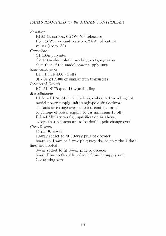
PARTS REQUIRED for the MODEL CONTROLLER
ResistorsR1R4 1k carbon, 0.25W, 5% toleranceR5, R6 Wire-wound resistors, 2.5W, of suitablevalues (see p. 50)
CapacitorsC1 100n polyesterC2 4700µ electrolytic, working voltage greaterthan that of the model power supply unit
SemiconductorsD1 - D4 1N4001 (4 off)01 - 04 ZTX300 or similar npn transistors
Integrated CircuitIC1 74LS175 quad D-type flip-flop
MiscellaneousRLA1 - RLA3 Miniature relays; coils rated to voltage ofmodel power supply unit; single-pole single-throwcontacts or change-over contacts; contacts ratedto voltage of power supply to 2A minimum 13 off)R LA4 Miniature relay, specification as above,except that contacts are to be double-pole change-over
Circuit board14-pin IC socket10-way socket to fit 10-way plug of decoderboard (a 4-way or 5-way plug may do, as only the 4 data
lines are needed)3-way socket to fit 3-way plug of decoderboard Plug to fit outlet of model power supply unitConnecting wire
53

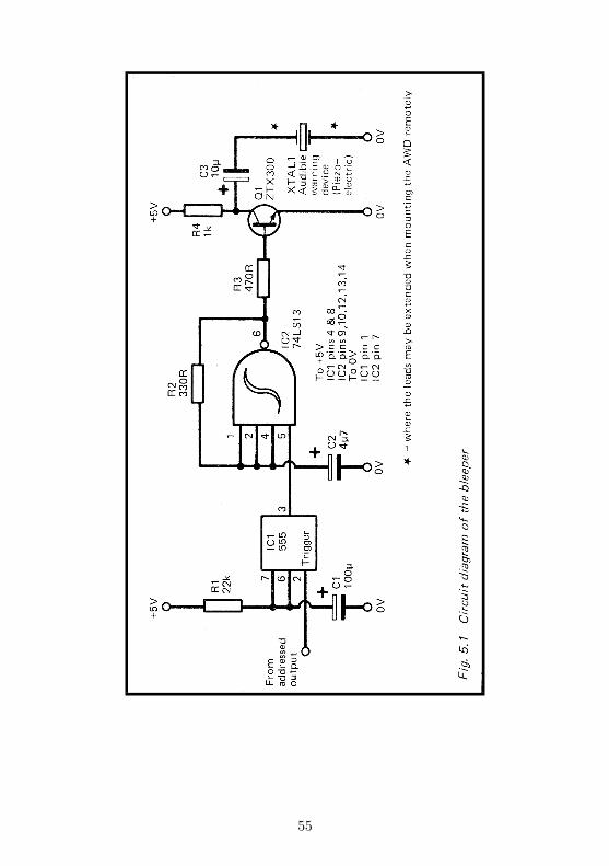
Project 5BLEEPER
A device which emits a short ’bleep’ when triggered by themicro has many uses in connection with games programs andin various applications around the home. Although the Spec-trum and Ace already have a built-in loudspeaker which can beprogrammed to ’bleep’, the loudspeaker is firmly fixed insidethe micro and can not be placed elsewhere. With this project,the micro can be in one room and the bleeper in another. Forexample, with the bleeper in the kitchen, you could use themicro as an egg-timer, ’bleeping’ at the ends of the cookingtimes which each member of the family prefers. If you havethe ZX81, then the bleeper is a valuable addition which willgreatly enhance many of your programs.
How it works
The note emitted by the bleeper is produced by an oscillatorbuilt from a single NAND gate (IC2, Fig.5.1). This gate hasSchmitt trigger inputs, which means that the output of thegate swings sharply when the input voltage reaches a certainvalue. The inputs of the gate are wired together (except forone, which we shall discuss later), so it acts as an inverter.When the inputs are ’high’ the output is ’low’, and when theinputs are ’low’ the output is ’high’. Suppose the input is lowto begin with, and the output is high. Current flows throughR2 and gradually charges the capacitor C2. When the voltageacross C2 reaches a certain level, this counts as a ’high’ input.The output swings low immediately. Now current flows fromC2 toward the output, which is at 0V. The capacitor graduallydischarges and the voltage across it falls. When it falls belowa certain level it counts as a ’low’ input and so the outputswings ’high’ again. In this way the output swings ’low’ and’high’ continuously.
The rate at which the circuit oscillates depends on the val-ues of C2 and R2. For the circuit to work, the value of R2
54
55
must lie between 330 ohms and 470 ohms, hut we can alter thevalue of C2 over a reasonably wide range to give a note of thechosen pitch. With the values shown in Fig.5.1, the pitch isabout 500Hz.
The duration of the ’bleep’ is controlled by a 555 timer IC,(IC1). This is wired so as to produce a single ’high’ pulse (atits output, pin 3), whenever a short ’low’ pulse is delivered toits trigger input (pin 2). The input pulse may be very shortindeed and in this circuit we use the pulse from an AddressedOutput of the decoder (Fig.D.1). The length of the outputpulse can be anything we choose, within reason. Its lengthdepends on the values of C1 and R1. The equation for calcu-lating the duration is:
t=1.1RC
where t is the time in seconds, R is the resistance of R1in ohms and C is the capacitance of C1 in farads. With thevalues given in Fig.5.1, the duration is about 2.4 seconds.
The output from the timer is normally ’low’. One inputof the NAND gate is held ’low’, so the gate is prevented fromchanging state. It can not oscillate and no sound is heard.When the timer is triggered, its output goes high for 2.4 sec-onds, during which time the NAND gate is able to oscillateand the ’bleep’ is heard.
The sound is made by a piezo-electric audible warning de-vice. This is a thin slice of crystalline material which vibrateswhen a pulsing signal is passed through it. It is rather likea crystal microphone or record-player cartridge, but workingin reverse. The output from the oscillator is insufficient todrive the crystal directly, so we use a transistor (Q1) which isswitched on and off by the output from the oscillator. Thisprovides enough power to make a suitably loud noise comefrom the crystal. If you prefer, a small loudspeaker may bewired in place of the crystal.
Building it
The project may be housed in any plastic case big enough tohold the scrap of circuit board on which it is assembled. It
56
needs only three wires from the decoder: 0V, +5V and oneof the address outputs. If you intend to use the bleeper inanother room at some distance from the micro, it is best forthe main part of the circuit to be in its case close to the microwith the crystal (or loudspeaker) on the end of a long pair ofwires leading to the other room.
One thing to think about before beginning constructionis the mounting of the audible warning device. The volumeof sound obtained is much greater if it is mounted on a firm(but not too firm) surface. The surface acts as a sounding-board, helping to transfer the energy from the crystal to theair around. Most crystals are already in a light metal case withmetal lugs attached (Fig.5.2). These lugs are pushed throughholes bored in the plastic case containing the circuit board (ora separate case, if the crystal is to be located in another room).Then the lugs may be bent flat to hold the device firmly againstthe wall of the case. If you are using a loudspeaker instead ofa crystal, mount it on the inside of the wall of the case, witha few holes bored in the case to allow the sound to escape.An old transistor radio set could be adapted for this purpose,provided that its loudspeaker is in working order. There is noneed to remove the ’works’ for there is sure to be enough roomto spare for the Bleeper board. Disconnect the loudspeakerfrom the radio circuit and connect it to the bleeper instead.
Apart from the points mentioned above, building the circuitis very straightforward. The device needs no address decodingother than that already done by the decoder. Simply run a3-way cable from one of the Addressed Output plugs of theboard.
The circuit may be tested by connecting it to a +5V or+6V supply. Usually it ’bleeps’ as soon as it is switched on.Temporarily connecting pin 3 of IC1 to the 0V line will makeit ’bleep’ again. If it does not, check the wiring carefully. Ifthe pitch of the note is not as required, substitute a differentcapacitor for C2. The larger its value the lower the pitch. If thelength of the ’bleep’ is not correct, alter C1 or R1. Changingeither or both of these to greater values, lengthens the ’bleep’.It is possible to have the note sounding for several tens ofminutes.
57
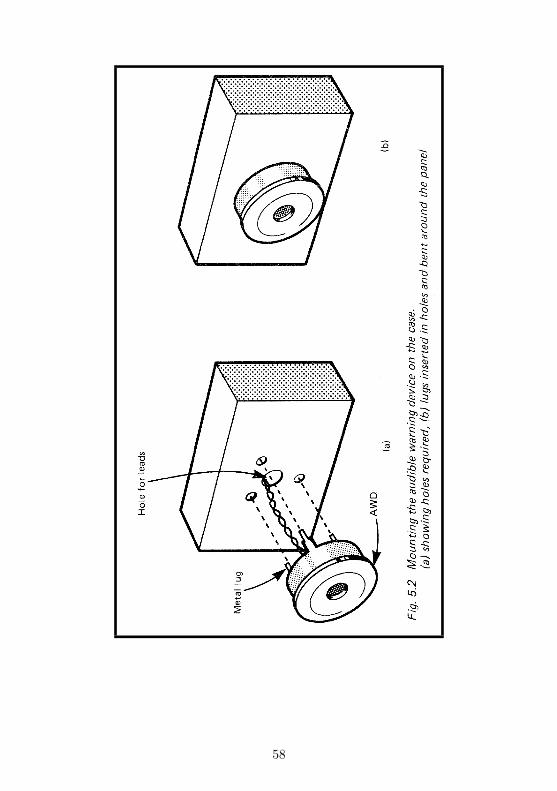
58
Programming
This could not be simpler. With the Spectrum, the commandOUT 31,0 causes the device to ’bleep’. This supposes you areusing the first Addressed Output, if you are using another one,use its address in place of the 31. The 0 is just a dummy value,for we are not actually sending any data to the bleeper. Youcould use any value in the range 0 to 255.
Programming is a little more complicated with the ZX81,for you first have to put the machine-code output programinto memory, as explained on p. 174. Having done this, usethe command LET X = USR 16514. If you have other devicesconnected at the same time, you will have to precede this byPOKE 16517, 31, or whatever address you have chosen for thebleeper.
With the Ace, a word to trigger the bleeper is defined likethis:
: BLEEP 0 31 OUT ;
The word BLEEP will then trigger the bleeper into action. Asabove, you should substitute the address you actually use forthe ’31’ in the definition.
PARTS REQUIRED for the BLEEPER
Resistors (carbon, 0.25W, 5% tolerance)R1 22kR2 330RR3 470RR4 1k
Capacitors (electrolytic)C1 100µC2 4µ7C3 10µ
SemiconductorQ1 ZTX300 or similar npn transistor
Integrated CircuitsIC1 555 timer1C2 74LS13 dual 4-input Schmitt trigger NAND gate
59

MiscellaneousXTAL1 Piezoelectric audible warning device, PCB mount-
ing (loudspeaker, 3 ohm to 15 ohm may be substituted)Circuit board8-pin IC socket14-pin IC socket1mm terminal pins (5 off)3-way socket to fit 3-way plug of decoder boardConnecting wire
60
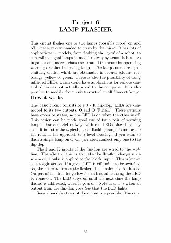
Project 6LAMP FLASHER
This circuit flashes one or two lamps (possibly more) on andoff, whenever commanded to do so by the micro. It has lots ofapplications in models, from flashing the ’eyes’ of a robot, tocontrolling signal lamps in model railway systems. It has usesin games and more serious uses around the house for operatingwarning or other indicating lamps. The lamps used are light-emitting diodes, which are obtainable in several colours red,orange, yellow or green. There is also the possibility of usinginfra-red LEDs, which could have applications for remote con-trol of devices not actually wired to the computer. It is alsopossible to modify the circuit to control small filament lamps.
How it works
The basic circuit consists of a J - K flip-flop. LEDs are con-nected to its two outputs, Q and Q (Fig.6.1). These outputshave opposite states, so one LED is on when the other is off.This action can be made good use of for a pair of warninglamps. For a model railway, with red LEDs placed side byside, it imitates the typical pair of flashing lamps found besidethe road at the approach to a level crossing. If you want toflash a single lamp on or off, you need connect only one to theflip-flop.
The J and K inputs of the flip-flop are wired to the +5Vline. The effect of this is to make the flip-flop change statewhenever a pulse is applied to the ’clock’ input. This is knownas a toggle action. If a given LED is off and is to be switchedon, the micro addresses the flasher. This makes the AddressedOutput of the decoder go low for an instant, causing the LEDto come on. The LED stays on until the next time the lampflasher is addressed, when it goes off. Note that it is when anoutput from the flip-flop goes low that the LED lights.
Several modifications of the circuit are possible. The out-
61
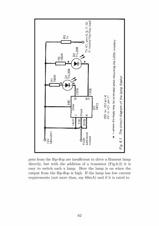
puts from the flip-flop are insufficient to drive a filament lampdirectly, but with the addition of a transistor (Fig.6.2) it iseasy to switch such a lamp. Here the lamp is on when theoutput from the flip-flop is high. If the lamp has low currentrequirements (not more than, say 60mA) and if it is rated to
62
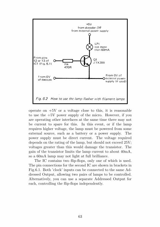
operate on +5V or a voltage close to this, it is reasonableto use the +5V power supply of the micro. However, if youare operating other interfaces at the same time there may notbe current to spare for this. In this event, or if the lamprequires higher voltage, the lamp must be powered from someexternal source, such as a battery or a power supply. Thepower supply must be direct current. The voltage requireddepends on the rating of the lamp, but should not exceed 25V;voltages greater than this would damage the transistor. Thegain of the transistor limits the lamp current to about 40mA,so a 60mA lamp may not light at full brilliance.
The IC contains two flip-flops, only one of which is used.The pin connections for the second IC are shown in brackets inFig.6.1. Both ’clock’ inputs can be connected to the same Ad-dressed Output, allowing two pairs of lamps to be controlled.Alternatively, you can use a separate Addressed Output foreach, controlling the flip-flops independently.
63
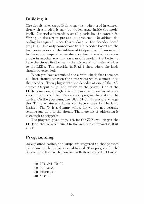
Building it
The circuit takes up so little room that, when used in connec-tion with a model, it may be hidden away inside the modelitself. Otherwise it needs a small plastic box to contain it.Wiring up the circuit presents no problems. No address de-coding is required, since this is done on the decoder board(Fig.D.1). The only connections to the decoder board are thetwo power lines and the Addressed Output line. If you intendto place the lamps at some distance from the micro (for ex-ample in another room, or on a mobile model) it is better tohave the circuit itself close to the micro and run pairs of wiresto the LEDs. The asterisks in Fig.6.1 show where the leadsshould be extended.
When you have assembled the circuit, check that there areno short-circuits between the three wires which connect it tothe decoder. Then plug it into the decoder at one of the Ad-dressed Output plugs, and switch on the power. One of theLEDs comes on, though it is not possible to say in advancewhich one this will be. Run a short program to write to thedevice. On the Spectrum, use ’OUT 31,0’. If necessary, changethe ’31’ to whatever address you have chosen for the lampflasher. The ’0’ is a dummy value, for we are not actuallysending any data to the circuit. The mere act of addressing itis enough to trigger it.
The program given on p. 176 for the ZX81 will trigger theLEDs to change when run. On the Ace, the command is ’0 31OUT’.
Programming
As explained earlier, the lamps are triggered to change stateevery time the lamp flasher is addressed. This program for theSpectrum will make the two lamps flash on and off 10 times:
10 FOR J=1 TO 20
20 OUT 31,0
30 PAUSE 50
40 NEXT J
64
An equivalent effect can be obtained on the Ace by defining theword WAIT (as on p.151 of the manual) and then this word:
: FLASH 20 1 DO 0 31 OUT WAIT LOOP ;
Entering FLASH causes the LEDs to flash on and off 10times.
Of course there is a lot more to programming than sim-ply making the LEDs flash. Commands are inserted in a widevariety of programs whenever the flip-flop is to change state.When using the LEDs as indicators, the rate of flashing canbe varied according to what information it is intended to con-vey. An interesting programming project would be to devise aMorse Code sender. This would be a helpful practice device.The user types in a message at the key-board of the micro.When ’Enter’ is pressed, the micro converts the message intothe equivalent symbols of the Morse Code and then flashes asingle LED to transmit the message.
PARTS REQUIRED for the LAMP FLASHER
ResistorsR1, R2 150R (2 off)
SemiconductorsD1, D2 TIL209 or similar light-emitting diodes (any colour,
2 off)Integrated Circuit
ICI 7473 dual JK flip-flop, with clear. (Note: thisproject requires the standard TTL version notLow-Power Schottky (LS) version.)
MiscellaneousCircuit board14-pin IC socket3-way socket to fit 3-way plug on decoder1mm terminal pins (3 off; 7 off if LEDs aremounted remotely)
65
Project 7LIGHT PEN
You may already have seen a light-pen being used with acomputer and know some of the ways in which it can be used.Often it is used to ’draw’ on the screen. The user moves thepen across the screen, just as if drawing, and a line appearson the screen, following the tip of the pen. This Light Pencan be used in the same way, though rather more slowly thanthe commercially made pens, but it has the advantage of beingextremely easy and cheap to build.
There are several other ways in which the light pen is used.For example, it is used in selecting choices from a ’menu’ dis-played on the screen. Beside each item there is a flashingpatch. You point the pen at the patch beside the item of yourchoice and the computer then does as requested. The sameidea can be applied to learning programs that have multiple-choice questions. A flashing patch appears next to each of theanswers. You point the pen at the patch beside the answerwhich you think is correct. Many people are unfamiliar withthe layout of a typewriter keyboard and perhaps slightly ap-prehensive about trying to use one. For such people it is easierto point with a light pen than to look at a keyboard and tryto find and press one of several possible keys.
There are applications for the light-pen in games too. In-stead of making your moves by using the key-board or a joy-stick, use the light-pen.
How it works
A light pen works by sensing light coming from the screen. Inthis design, the sensor is a light-dependent resistor or LDR,often called a cadmium sulphide photoconductive cell (PCC).The resistance of an LDR is inversely proportional to the amountof light falling on it. Its resistance is very high in darkness (amegohm or more), but decreases to only a few hundred ohmswhen it is in the light. In Fig.7.1, R4 is the LDR. It is in
66
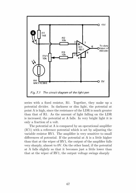
series with a fixed resistor, R1. Together, they make up apotential divider. In darkness or dim light, the potential atpoint A is high, since the resistance of the LDR is much greaterthan that of R1. As the amount of light falling on the LDRis increased, the potential at A falls. In very bright light it isonly a fraction of a volt.
The potential at A is compared by an operational amplifier(IC1) with a reference potential which is set by adjusting thevariable resistor RV1. The amplifier is very sensitive to smalldifferences of potential. If the potential at A is a little higherthan that at the wiper of RV1, the output of the amplifier fallsvery sharply, almost to 0V. On the other hand, if the potentialat A falls slightly so that it becomes just a little lower thanthat at the wiper of RV1, the output voltage swings sharply
67

upward, almost to +5V. In this way the circuit gives a lowoutput in darkness or dim light, and high Output in brighterlight. There is a rapid swing at a fixed level of brightness. Wecan choose this threshold level by the position in which RV1 isset.
The output from the amplifier is a clear-cut signal which isentirely suitable for feeding to a TTL logic gate. The outputis taken directly to one of the Data Input terminals on thedecoder (Fig.D.1).
Building it
The circuit is connected to the decoder board by only threewires: the two power lines, and a wire to one of the DataInput plugs. There are two wires going to the LDR and two tothe variable resistor, which is best mounted on the case of theproject. It is possible to use a miniature preset resistor for RV1,and to set the level once and for all. However, it is convenientto be able to adjust the threshold level occasionally, especiallyif you are using displays with backgrounds of differing colours,so a ’volume control’ type is preferred.
Almost any type of LDR can be used with this project.The one specified is a relatively small one, measuring 8mmin diameter. One of the larger types, such as the ORP12,will work just as well. The resistance ranges of different typesvary; the resistance of R1 should be about the same as thatof the LDR in average room lighting conditions. If necessary,substitute a resistor of different value for R1.
There is scope for experimentation and ingenuity in makingthe pen. In its simplest form (Fig.7.2) it consists of a tube intowhich the LRD fits fairly tightly. The LRD needs to be setback about 3cm from the open end so as to confine its field ofview to a small area of the screen. With the ZX computers thesize required is a little smaller than one of the graphics blocks.The actual dimensions of this depend on the size of the screenof your TV. With the tube held close to the screen the LDRshould receive most of the light from a single graphics block,but none from adjacent blocks. It will help if the inside of thetube is painted dull black. Use a felt-tip spirit marker for this.If you use a metal tube, take care to cover its end with a softer
68
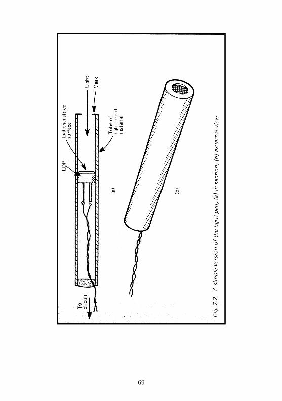
69
or more flexible material so that there is no danger of scratch-ing the front surface of the TV tube. If you are using one ofthe larger LDRs, the tube into which it fits needs masking atone end to reduce the view to a single graphics block. A widertube may make it more difficult to see the screen when youare drawing, so a better plan is to make a tube which taperstoward the open end.
A simple tube must be held close to the screen, almosttouching it, to sense light from the selected area only. If youfit a small lens to the end of the tube and adjust the positionof the LDR so that light from a small area of the screen isconcentrated on it, you will be able to hold the pen furtheraway. The only difficulty then is that it becomes harder toknow exactly where the pen is pointing.
When the circuit is complete, connect it to a power supply(+5V or 4-6V) and connect a voltmeter to the output of IC1.Switch on the micro and the TV. Print a black graphics blockon the screen, if the background is white, or print a white blockon a black ground. Point the pen squarely and accurately ata white area of screen. Adjust R1, if necessary, to make thevoltmeter read +5V (or a reading very close to this). Nowmove the pen to point to a black area. The voltage falls almostto zero. If it does not, RV 1 needs further adjustment. Youwill soon find the position of R1 in which the voltage swingssharply to 0V or +5V as the pen is pointed at white or blackareas.
The Light Pen may now be plugged into the decoder andtested on the micro. Here is a simple test program for the ZX-Spectrum:
10 PRINT AT 20,20;"[][]"
20 PRINT AT 21,20;"[][]"
30 PAUSE 5
40 PRINT AT 10,10; IN 31
50 PRINT AT 20,20;" "
60 PRINT AT 21,20;" "
70 PAUSE 5
80 PRINT AT 10,10; IN 31
90 GO TO 10
70
Users of ZX81 will need to modify this program as explainedon p. 174. If your pen is attached to one of the other DataInput plugs, alter the address in lines 40 and 80 accordingly.This program puts a flashing square of four graphics blocks onthe screen. Point the pen at the square. As it flashes, youwill see the number (which indicates the input) alternatingbetween 255 (white) and 254 (black). This is because unuseddata lines count as ’high’ while the used line (D0) is alternatingbetween ’high’ and low’. This gives binary numbers 1111 1111(=255) and 1111 1110 (=254) respectively. When you movethe pen away from the square to point at a white area of screen,the number stays at 255. If you cover the end of the pen toexclude the light, the number stays at 254. If you do not getthe changes described here, it is likely that RV1 may needfurther adjustment to put the threshold point in the range ofbrightness of your TV.
The pauses in this program give the pen time to respond tothe changes in brightness, and also gives you a chance to seethat the pen is responding correctly. The lengths of the pausescan be reduced to PAUSE 3 and, with more precise adjustmentof RV1, eliminated altogether.
Programming
Although this is such an easy project to build, you need tothink out the programming very thoroughly. The two mainways of using it are (i) to select a choice from a menu or otherdisplay on the screen, and (ii) to draw on the screen. Letus consider choice selection first. The choices (items of themenu, answers to a question etc.) are printed on the screenwith a flashing patch beside each one (Fig. 7.3). The bestapproach is to print the choices first then to print the patchesusing PRINT AT. The patches need be only a single graphicsblock in size, so you alternately print a white block (a space)and a black block (an inverse video space) in quick succession.The trick is to flash only one patch at a time. We begin witha white screen. Then (supposing there are three choices andthree patches) patch no. 1 is made black. This is followed bya pause (say, PAUSE 3) after which the input from the pen isread. If the pen is already pointing at that patch its output
71
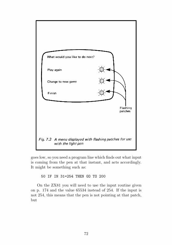
goes low, so you need a program line which finds out what inputis coming from the pen at that instant, and acts accordingly.It might be something such as:
50 IF IN 31=254 THEN GO TO 200
On the ZX81 you will need to use the input routine givenon p. 174 and the value 65534 instead of 254. If the input isnot 254, this means that the pen is not pointing at that patch,but
72
possibly at one of the other patches. So patch no 1 is madewhite again and patch no 2 is made black. After a pause, comesanother line to read the input from the pen, perhaps like this:
80 IF IN 31=254 THEN GO TO 450
If this test fails, the pen is not pointing at patch no 2 -perhaps it is at patch no 3, or possibly it is just pointing atsome other part of the screen. The next step is to flash patchno 3. If the pen is not there either, the program goes roundin a loop to flash the patches in order again. Sooner or laterit finds the pen in this way and the micro is sent to one of anumber of sub-routines according to which patch the pen ispointing.
You may have noticed the slight complication that if thepen is not pointing at the screen at all, its output is ’low’ all thetime and the test at line 50 will succeed, sending the programto line 200. One way of dealing with this is to keep the penpointed at the screen when it is not being used. Another is tomake the program wait until the pen is certainly pointing atthe screen:
40 IF IN 31=254 THEN GO TO 40
A line like this is needed before all the lines which make thepatch black. This ensures that the input really is 255 beforethe micro makes the patch black and tests if it changes to254. There are various ways of programming for drawing onthe screen. The commercial systems find out where the penis pointing by scanning the whole screen, row by row, witha moving flashing patch. The input from the pen is read atevery point. When the patch reaches a point at which its flashis followed immediately by a change in output from the pen,the micro knows that it has ’found’ the pen. It plots a blackgraphics block there (or white if the background is alreadyblack). This kind of program is not too hard to write, butunless you write it in machine code, it is extremely slow. Alsothe time required for this simple pen to respond to the flashwould still make it a very slow program. There are two waysof speeding things up. One way is to
73
make the drawing start at a fixed point on the screen. Theprogram scans only the 8 blocks adjacent to this area, tryingto find out where the pen has moved to. When it finds the penit plots a mark at the new position of the pen. Then it scansthe 8 areas adjacent to this area, and so on.
Here is the program, to run on a Spectrum:
10 DIM s(21,31)
20 LET y=10
30 LET x=15
40 PRINT AT y,x;"[]"
50 LET s(y,x)=1
60 PAUSE 5
70 IF IN 31=255 THEN GO TO 60
80 LET j=y-1
90 LET k=x-1
100 PAUSE 5
110 IF IN 31=254 THEN GO TO 100
120 IF s(j,k)=1 THEN GO TO 170
130 PRINT AT j,k;"[]"
140 PAUSE 5
150 IF IN 31=254 THEN LET y-j:
LET x=k: LET s(j,k)=1: GO TO 80
160 PRINT AT j,k;" "
170 LET k=k+1
180 IF k<x+2 THEN GO TO 100
190 LET j=j+1
200 IF j<y+2 THEN GO TO 90
210 STOP
This program is easily adapted for the ZX81 (see p. 174).It is worth while studying this program in some detail as itillustrates several points of importance in operating the lightpen successfully. First of all the program sets up an array (line10) which holds a ’map’ of the screen. The idea of this is tokeep a record of which squares have been drawn on. Though itis possible to PEEK the video RAM for this information, thereare three equations to be used in different areas of the screen.This is too complicated. Unfortunately, having to set asidememory for the array means that this program needs more
74
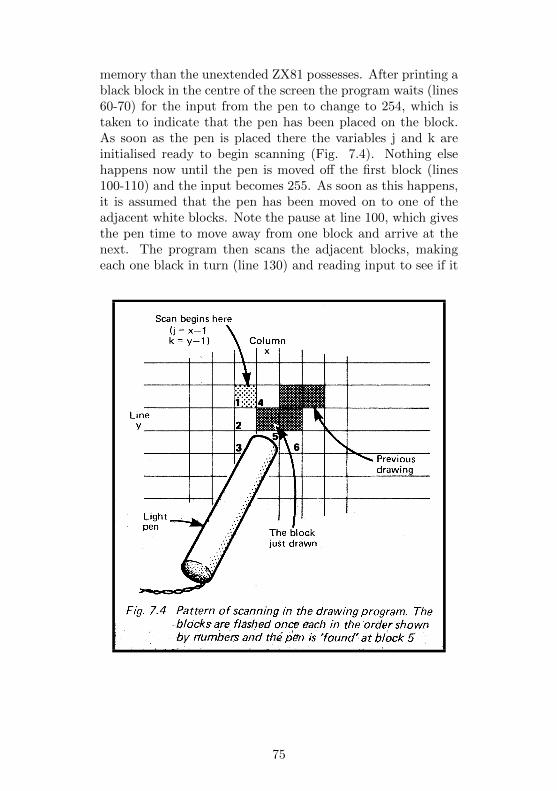
memory than the unextended ZX81 possesses. After printing ablack block in the centre of the screen the program waits (lines60-70) for the input from the pen to change to 254, which istaken to indicate that the pen has been placed on the block.As soon as the pen is placed there the variables j and k areinitialised ready to begin scanning (Fig. 7.4). Nothing elsehappens now until the pen is moved off the first block (lines100-110) and the input becomes 255. As soon as this happens,it is assumed that the pen has been moved on to one of theadjacent white blocks. Note the pause at line 100, which givesthe pen time to move away from one block and arrive at thenext. The program then scans the adjacent blocks, makingeach one black in turn (line 130) and reading input to see if it
75
has fallen to 254. However, before leaving this it looks to seeif this block has already been drawn on and, if so, (line 120)skips the flashing routine. This prevents the program fromerasing a block it has already drawn. If the pen happens tobe pointing at one of these blocks by mistake, odd things mayhappen. Even this fairly elaborate program needs improving!
If it ’finds’ the pen (line 150), it updates the values of xand y, (representing the current position of the pen), to thevalues of k and j, (the coordinates of the square being flashed).A black block is printed there and is also recorded in arrays. Having done this, the program begins again from line 80,basing its scan on the new values of x and y. When using thisprogram it is important to move the pen to exactly where youwant the next block to be. If it is half-way between one blockand the next, flashing either block may fail to reduce the inputto 254, because of light reaching the pen from the unflashedblock. In this event the scan fails to ’find’ the pen and theprogram runs through to the end. Rather than lose a drawingby such an accident, position the pen correctly, then type inthe direct command GO TO 80.
Another approach to programming relies on the DRAWcommand of the Spectrum and Ace. Scan the whole screen,row by row with a flashing patch. This takes longer thanmerely scanning adjacent squares but time is saved when thepen is ’found’, for the program can be made to DRAW a linedirectly from the last location of the pen to the present loca-tion. Another variation is to use the CIRCLE command. Pointthe pen where the centre of the circle is to be. The screen isscanned and this point ’found’. Then point the pen at anypoint location on the circumference of the circle to be drawn.The micro ’finds’ this, computes the radius and plots the circle.You could work out similar programs to plot squares, trianglesor other shapes.
PARTS REQUIRED for the LIGHT PENResistors (carbon, 0.25W, 5% tolerance)R1 1K8 (depending on average resistance of R4)
76

R2, R3 10k (2 off)Other Resistors
MKY7C38E light-dependent resistor: dark resistance 300k,sunlight resistance 100 ohms:ORP12 is possible alternative but largerRV1 10k variable potentiometer
Integrated CircuitIC1 7611 CMOS operational amplifier
MiscellaneousCircuit board8-pin IC socket3-way socket to fit 3-way pin on decoderKnob for RV11mm terminal pins (7 off)Materials for making the body of the penConnecting wire, including light flexible wire for the leadto the pen
77
Project 8MAGNETIC CATCH
This circuit has a once-for-all action. It is reset manually andremains reset until triggered by the micro. Triggering leads tosome kind of mechanical action. After this, it must be resetmanually again. Exactly what action occurs when the catchis triggered depends on the application to which it is put. Itcould be triggered to release the bolt on a door, so, for ex-ample, letting the cat out early in the morning. Or maybethe bolt is on the door of a cupboard which is to be openedonly when the correct secret password is typed into the com-puter. It could be used to discharge a quantity of food intoan aquarium, so overcoming the problem of feeding the fishon Saturday evening when you are away for the weekend. Ifyou are away for the day, and if the thermometer of Project15 is used to monitor the temperature in your greenhouse, themagnetic catch can be triggered by the micro when the tem-perature gets too high. It opens the window or door or letsthe sun-blinds roll down over the roof.
How it works
The action of the catch depends upon briefly energising a coil,or solenoid. There is a sliding soft-iron core partly inside thesolenoid. When a burst of current flows, the magnetic field socreated pulls the core swiftly into the solenoid. This motion isused to perform whatever mechanical action is required. Oneof the problems with solenoids is that the more powerful oneshave coils with a relatively low resistance. They would drawtoo much current from the micro. If a battery supply was pro-vided, the batteries would soon be exhausted if the coil were toremain energised for periods of a few hours. This circuit usescapacitors to store the energy needed to activate the solenoid(Fig.8.1). When the circuit is being reset, button S1 is pressedand charges the capacitor up to maximum voltage. If the sup-ply is taken from the micro this is +5V. If the solenoid
78
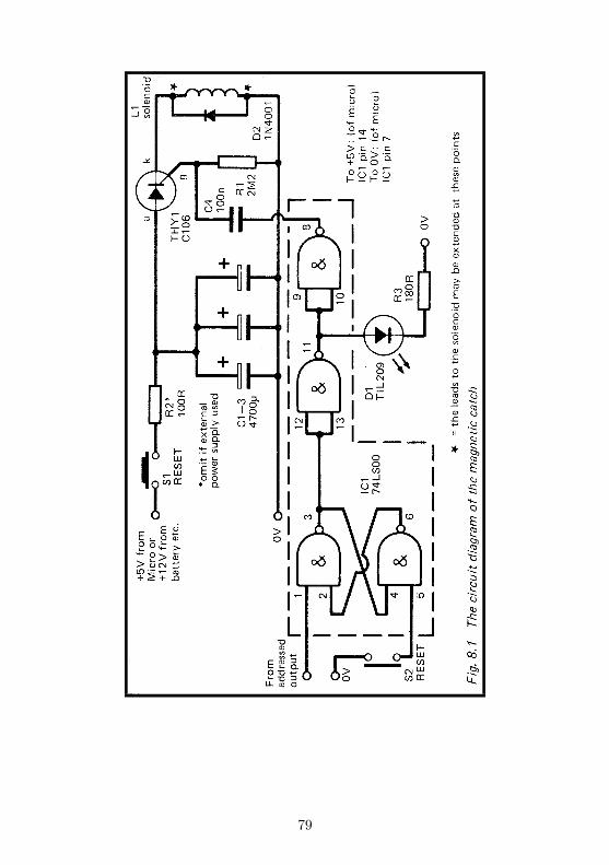
79

requires a higher voltage for satisfactory operation, it is chargedfrom a battery or other external supply.
The capacitors are prevented from discharging through thesolenoid immediately because there is a thyristor in the circuit.This does not conduct until a high pulse is sent to its gateelectrode (g). Otherwise the capacitors remain charged formany hours, and during this time the only power required tooperate the catch is that needed by IC1 (about 8mA).
The gate electrode is held at low voltage by resistor R1.The gate is also connected, through a coupling capacitor C4and two inverting gates, to the output of a flip-flop. Whenthis flip-flop is reset by pressing S2, its output goes low. Theinverted output goes ’high’, putting the LED on to indicatethat the circuit is now reset. The doubly inverted output goes’low’.
The flip-flop is triggered by a low-going pulse from an Ad-dressed Output of the decoder (p. 158). When the microaddresses the catch, the flip-flop changes state. The LED isturned off and a high pulse passes through C4 to the gate ofthe thyristor. This causes the thyristor to begin conducting. Itconducts very easily and the capacitors are discharged almostinstantaneously through the solenoid. This creates the strongmagnetic field required to operate the catch. Once the capac-itors have been discharged, no further action occurs until theflip-flop has been reset and the capacitors have been recharged.
If the capacitors are to be charged from the +5V supply ofthe micro, it is essential to include a resistor (R2) in the charg-ing circuit. Otherwise, the sudden drain on the power supplyof the micro is too great and its program is lost. The resistorreduces the charging current to a manageable amount, thoughit then takes about 10 seconds to recharge the capacitors.
The mechanical side of the project is left to the ingenuity ofthe reader, for so much depends on the application for whichit is intended, the strength of the particular solenoid used,and the skill of the reader in constructing mechanical devices.Fig.8.2 shows how a pull from the core can be made to releasea prop, so causing a window (e.g. of a greenhouse) to fall shutunder the action of gravity. Fig.8.3 shows how a
80
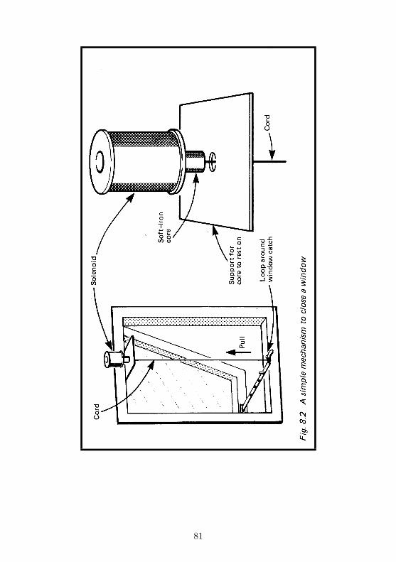
81
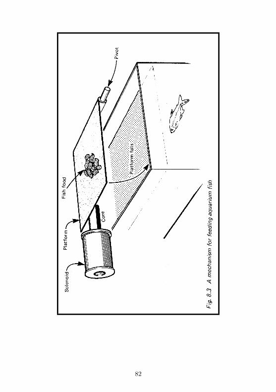
82

platform carrying the required daily quantity of fish food maybe released, so scattering the food into the aquarium below.
As an alternative to a solenoid with a sliding core, thereader may prefer to use a solenoid with a fixed core which at-tracts a moving armature. An old electric bell or buzzer couldbe adapted for this purpose. Fig.8.4 shows how the motionof an armature can release a sprung lever, so initiating a rela-tively more forceful operation.
83
Building it
The catch needs no address decoding other than that alreadyprovided for on the decoder board (Fig. D.1). It requires threewires to connect it to the board; the two power lines, and thewire connecting it to an Addressed Output. The circuit shouldbe connected to the micro by fairly short wires. If the solenoidis to be located at some distance from the micro its leads maybe extended at the points marked * in Fig.8.1. The circuitis best housed in a case, on which are mounted the two pushbuttons and the LED. If you are using a battery for charging,the case needs to be large enough to hold this too.
It is best to design, build and test the mechanical side of thecatch before constructing the electronic side. It is essential tomake certain that the solenoid you intend to use will developenough power to actuate the mechanism. You can connectthe capacitors together on a bread-board or by leads endingin crocodile clips. Then charge them from a battery and trydischarging them through the solenoid. If the force developedis insufficient, there are several ways of increasing it:
i Begin with the moving core further inside the coil (thoughthis also reduces its length of travel)
ii Use a solenoid with more turns of wireiii Add more capacitors in series with C1C3iv Charge the capacitors to a higher voltage (assuming this
is within the rating of the solenoid
It is also worth while checking that the mechanical design issound. For example, parts that are supposed to slide shoulddo so smoothly, without undue friction. A transverse forceapplied to the care by the weight of an attached lever mayprevent it from sliding easily into the solenoid. Once assem-bled, the electronics are tested for short-circuits between thelines which connect it to the micro. It is then ready for testingon the micro. Plug it on to the decoder board. Key in thisshort program:
10 OUT 31,0
This simply addresses Addressed Output 0. If you are using
84

another address, as in Table D.2, substitute this in the lineabove. Running the output program on p. 176 has the sameaction with the ZX81. On the Ace, use 0 31 OUT.
Press S2 to reset the flip-flop; the LED comes on. Nextpress S1 to recharge the capacitors. Hold the button presseddown for about 10 seconds if you are charging from the micro’sown power supply. Reset the mechanism so that it is readyto be triggered. When all is reset, RUN the program. Thesolenoid is energised, the mechanism is operated and the LEDgoes out.
Programming
The essential program line is the one given above. Apart fromthat, the rest depends on the application.
PARTS REQUIRED for the MAGNETIC CATCH
Resistors (carbon, 0.25W, 20% tolerance)R1 2M2R2 100R (required if micro power supply used for charging)R3 180R
CapacitorsC1C3 4700/..1 electrolytic (3 off)C4 100nF polyester
SemiconductorsTI L209 or similar light-emitting diodeD2 1N4001THY1 C106 or similar thyristor
Integrated CircuitIC1 74LS00 quadruple 2-input NAND gate
MiscellaneousLi Solenoid with soft-iron moving core, rated to operate at
6V, 12V etc. (alternatively an old electric bell, buzzer or relay)Si, S2 Push-to-make Push-button switches (2 off)Circuit board14-pin IC socket3-way socket to fit 3-way plug of decoder
85

1mm terminal pins (9 off)Parts for making mechanismConnecting wire
86
Project 9LAP SENSOR
Although this Project is called ’Lap Sensor’, it has many otherapplications. In its original application as a lap sensor for slot-car racing, it detects when a car passes a given point on thetrack. Depending on how the micro is programmed, it cankeep count of the number of laps, it can measure the lap time,or it can do both things at once. From this information it cancalculate and display the lap speed and the race speed. Sincethe device works by the breaking of a beam of light passingacross the track it does not matter what it is That breaks thebeam. It could equally well be used for bicycle races, horseraces or in many kinds of athletic track events.
Likewise, it does not have to count how many times thesame object breaks the light beam, but could be counting howmany times different objects break the beam. It can countpeople going into a room, cars going into a car park, or objectson a conveyor belt. It works so fast that it can count objects (orother causes of interruption of the beam) which come so quicklyin succession that it would be difficult, if not impossible, tocount them by eye.
Another class of application is that in which we want thecomputer to wait for and act on a single interruption of thebeam. An obvious example is in connection with intruder de-tection. A beam of light across a corridor is broken by theintruder. The micro detects this and sounds the alarm. Itcould even be programmed to detect the setting of the Sunand then switch on the porch light!
How it works
The light is detected by a photodiode (D1, Fig.9.1). This re-ceives light from a source some distance away. A special lampmay be provided to focus a well-defined beam across the trackor corridor, but this is not always essential. If a table-lampwith a 60W bulb is placed on one side of a corridor and
87
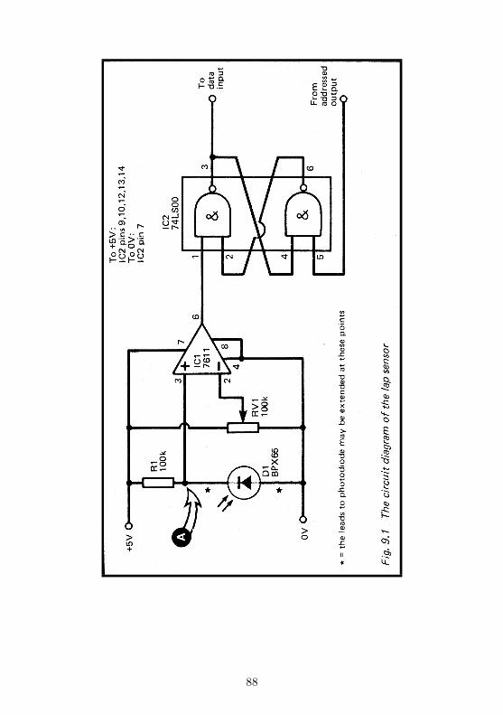
88

the photodiode is on the opposite side, pointing at the lamp,the shadow of a person passing between them is sufficient totrigger the sensor. On the smaller scale, (for example, on theslot-car track or model railway), an unshaded 6V 60mA torchbulb placed 10cm or slightly more from the lamp is entirelysuitable as a source of light. The only point to look out foris that other lamps in the vicinity do not shine on the photo-diode when the light from the source lamp is supposed to beinterrupted.
The photodiode works best with light from filament lamps,but is relatively insensitive to light from fluorescent tubes. Itworks with daylight but, since the intensity of daylight variesso much with cloudiness and time of day, this is not a reliablesource.
The photodiode is connected so that it is reverse-biassed.The amount of leakage current increases in proportion to theamount of light falling on the photodiode. As the current in-creases the PD across the diode increases, so the potential atpoint A rises. The operational amplifier IC1 compares the po-tential at point A with a standard potential at the wiper ofthe variable resistor RV1. We adjust the standard potential tobe very slightly less than the potential at A when the beam oflight is unbroken. The tiny difference of potential is amplifiedand the output of IC1 swings sharply to +5V (’high’). Whenthe beam is broken, the current through D1 decreases, the po-tential across D1 decreases, and the potential at A falls belowthat of the wiper of RV1. The potential difference between theinputs may still be tiny, but it is now a difference in the oppo-site direction. Consequently, the output of IC1 swings sharplyto 0V (’low’). We can adjust RV1 to allow for the brightnessand distance of the light source.
The output of IC1 goes to a flip-flop (IC2). The flip-flop isreset by a low pulse from an Addressed Output of the decoder(p. 158). In this state, its own output goes ’low’. The outputof the flip-flop is connected to a Data Input of the decoder.In the ’reset’ state the computer reads this output as a 0 ondata line D0. When the beam of light is broken, even for afew milliseconds, the flip-flop is triggered to change state. Itsoutput goes ’high’. When the micro next reads from the LapSensor’s
89
address, it finds a 1 on line D0. The flip-flop remains in thisstate indefinitely, so it does not matter if the micro does notread the lap sensor immediately after the flip-flop has beentriggered. This means that the micro does not miss brief in-terruption of the beam if it happens to be engaged in someother part of its program at the time it occurs.
When the micro has read the lap sensor and found that ithas been triggered, it resets it by writing to its address. Thiscauses a low pulse to appear at the Addressed Output, andthis triggers the flip-flop to reset. Now it is ready to detect thenext interruption of the beam.
Building it
The circuit is housed in a small case with the potentiometerRV1 mounted on it. The photodiode can be hidden inside thecase, with an aperture cut in the wall to allow light to enter.This arrangement helps screen off unwanted light from othersources. In certain applications it may be more convenient tohave the light source and photodiode at some distance fromthe micro, perhaps in another room. In this even, the circuitshould be close to the micro, but the leads to the photodiodemay be extended where marked * in Fig.9.1.
The circuit does not need any special address decoding, soit requires only 4 wires to connect it to the decoder board: thetwo power lines, and connections to an Addressed Output anda Data Input, preferably having the same address.
There are no difficulties in wiring up the circuit. When itis complete, connect it to a power supply (+5V or +6V) andconnect a voltmeter to point A. Point the photodiode towarda nearby light source (e.g. a table lamp). As you place yourhand between the lamp and the photodiode, the voltage at Ashould rise. Then connect the voltmeter to the output of IC1.Adjust RV1 until the output just swings to +5V. Interruptingthe beam makes it swing sharply to 0V. Finally connect thevoltmeter to the output of the flip-flop (pin 3, IC2). Brieflyconnect pin 5 to the 0v line to reset the flip-flop. Its outputgoes high (+2.5V or slightly more). When the light beam isinterrupted, the output falls to ’low’ (close to 0V). The circuit
90
is now ready to be tested on the micro.
Here is a simple test program for the ZX81. First of all typein and run the combined input-output routine given on p. 177.Remember to include the correct value for the address (TableD.2). Then delete lines 20 to 70 and type in the following:
20 LET X = USR 16514
30 PRINT X
40 LET X = USR 16521
Line 20 reads the output from the Sensor. If it has been trig-gered, line D0 is high, and so X takes the value 65535 (see p.9). If the device is not triggered, the value is 65534. Line 30prints the reading and the sensor is reset by the write com-mand given in line 40. Run the program once just to reset thesensor. Then run it again; since you have not broken the beambefore running it, ’65534’ is displayed. Now break the beamby placing your hand in it. The next time the program is run,the figure ’65535’ is displayed.
On the Spectrum the corresponding program is:
10 PRINT IN 31
20 OUT 31,0
Use another address if possible. The values 254 and 255are obtained.
Programming
The commands to read and to reset the lap sensor are easyenough to understand, but there are one or two points to con-sider when using them. Take as an example this program forthe Spectrum:
10 LET n=0
20 OUT 31,0
30 IF IN 31=254 THEN GO TO 30
40 LET n-n+1: PRINT n
50 OUT 31,0
60 IF IN 31=255 THEN GO TO 50
70 GO TO 30
91
This is a program to count how many times the light beam isbroken. It could be used for purposes such as those describedon p. 87. Line 10 initialises the counter variable, n. Line 20resets the sensor, just in case it goes into the ’set’ conditionwhen the power was first switched on. Line 30 waits for theflip-flop to become ’set’. As soon as the beam is broken theinput becomes 255 and the program drops through to line 40.Here the counter n is incremented and n is displayed. At line50 the micro attempts to reset the sensor ready to count thenext interruption. But micros work more quickly than mostobjects move, so it is likely that the beam is still broken. If thisis so, the sensor will not reset. The micro waits in a loop (lines50 and 60) continually attempting to reset the sensor and thenreading it to find if it has been successful. Eventually, when theobject has moved out of the beam and the light level is restoredto normal, the sensor resets and line 60 detects that this hashappened. The program then goes to line 70 and back to line 30to wait for the next interruption. This example demonstratesthat it is essential to reset the sensor at the beginning, and toallow the beam to be restored and confirm that the sensor hasbeen reset after each interruption.
Lap timing programs need two routines similar to lines 30,50 and 60 above, to detect an interruption and then reset thesensor. At the first interruption the time is recorded using themicro’s internal clock. At the second interruption the timeis taken again. The difference is the lap time. You read themicro’s internal clock by PEE King certain addresses. For theSpectrum the expression is:
LET time=(65536* PEEK 23674+256b* PEEK 23673 +
PEEK 23672) /50
In the USA the divisor is 60. Details of how to use this ex-pression are given on p.130 of the manual. For the ZX81 theexpression is:
LET =(256* PEEK 16437 + PEEK 16436) /50
Again, the divisor 60 is used in the USA. On the ZX81, theexpression allows timing of periods up to about 9 hours, butdo not use the PAUSE command during this time, for it alters
92

the values contained in the two addresses. Indeed, for timingperiods of more than a few seconds, it is easier to make thecomputer wait for, say PAUSE 100 (one second) and count thenumber of PAUSES between the first time the beam is brokenand the second time it is broken. This gives the Lap time tothe nearest second.
Page 142 of the Jupiter Ace handbook describes some wordsfor timing on this machine.
PARTS REQUIRED for the LAP SENSOR
ResistorsR1 100k carbon, 0.25WRV1 100k variable potentiometer
SemiconductorBPX65 photodiode (or almost any type)
Integrated CircuitsIC1 7611 CMOS operational amplifierIC2 74LS00 quadruple 2-input NAND gate
MiscellaneousCircuit board and caseKnob for RV18-pin IC socket14-pin IC socket3-way sockets to fit 3-way plugs on decoder board (2 off)lmm terminal pins (9 off)Connecting wireA source of light
93

Project 10PHOTO-FLASH
There are really two sections to the project, and you may useeither one of them or both together. One section allows themicro to fire a photographic flash-gun. The other section is asound sensor. The two are intended to be used together to firethe flash-gun when a sound is heard. One application of this isin high-speed photography. The camera is aimed at an inflatedballoon (or even a glass bottle). The lights are turned out andthe shutter is opened. Prick the balloon with a pin (or strikethe bottle with a hammer) and the resulting noise triggers theflash. The result is a photograph of the bursting balloon orbreaking bottle. Of course, a sound sensor could be connecteddirectly to a circuit to fire a flash-gun, but having these cir-cuits interfaced to a micro means that you can program themicro to delay the firing until a fixed period of time after thesound occurs. In this way you can obtain photographs takenat different intervals after the initial impact. With more thanone flash circuit, the micro could fire a succession of flashes,producing multiple images on one frame.
Another application is to take photographs of nocturnalanimals. A noise made by the animal triggers the flash. Thesound detection circuit can be used on its own in many ways.It is particularly sensitive to sharp noises (clapping, snappingfingers) and to the higher-pitched whistles, so it provides a wayof controlling the micro by sound. This section of the projectcould be used in conjunction with Project 4 to control theaction of a model locomotive or slot-car by blowing a whistle,by clapping your hands, or by calling out ”Go!” or ”Stop”.Project 8, the Magnetic Catch is another one which can becontrolled by sound, through the agency of the micro.
The photo-flash section can also be used on its own, per-haps simply to give a timed delay in taking a photograph of agroup when you want to be included in the picture. Project9 can be useful with the photo-flash. Instead of triggering theflash by sound, why not trigger it when a beam of light isbroken?
94
How it works
The photo-flash section is controlled by an Addressed Outputwhich is connected to a flip-flop (Fig.10.1). The flip-flop is re-set by pressing S1. Its output is then ’low’. When the deviceis addressed, the low pulse from the Addressed Output setsthe flip-flop. Its output goes ’high’ switching on transistor 01.The coil of RLA1 becomes energised and the contacts of therelay are closed. The relay contacts are connected across theterminals of a flash gun, which then fires. Note that power tooperate the flash comes from the flash-gun, not from this cir-cuit. The relay contacts do the same job as the contacts insidethe camera which are normally used for firing the flash. Oncethe flash has been fired, the flip-flop must be reset manuallybefore the flash can be fired again. It is possible to dispensewith S1 and wire pin 5 of IC2 directly to another AddressedOutput. This would allow the micro to reset the flip-flop readyfor another photograph. If you are using the kind of flash-gunwhich requires flash-bulbs to be renewed there is little pointin doing this. If you have an electronic flash-gun, it is possibleto program the micro to make multiple exposures by firing thegun again after a short interval.
The sound sensor takes the signal from a crystal micro-phone and amplifies it by the operational amplifier IC1. Inthe absence of sound the output from the amplifier is about2.5V. When sound is detected it oscillates above and belowthis level. Low-going voltage changes act as a low pulse to theother flip-flop, causing it to set. Its output, which is normally’low’, changes to ’high’. This can then be read by the micro.Note that the flip-flop stays high once it has been set, so itdoes not matter if the micro is not actually reading data fromthe sensor at the instant the sound occurs.
The flip-flop is reset by pressing S2. For the original appli-cation of this project, manual resetting is all that is required.However, in some applications it might be convenient to havethe micro do the resetting. This is done by replacing S2 witha wire from pin 13 of IC2 direct to an Addressed Output ofthe decoder. This allows the micro to reset the flip-flop aftera sound has been detected, ready to detect the next sound.
95
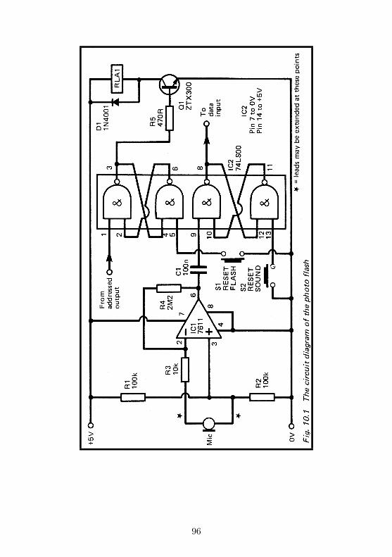
96
The device needs a minimum of four lines to connect it tothe micro: the power lines, plus connections to an AddressedOutput and a Data Input. It needs more lines if either ofthe flip-flops are to be reset by the micro, instead of beingreset manually. Assuming either that the flip-flops are to bereset manually or, that they are to be reset by the micro usingseparate Addressed Outputs, all address decoding is done bythe decoder, and there is no need to provide for this in theproject itself.
The photo-flash should be housed in a case, on the outsideof which the microphone can be mounted. The two pushbut-tons are mounted on the panel of the case. The switch contactsof the relay are wired to a socket, on the panel of the case. Youneed a plug to fit this socket, with wires leading to the flash-gun.
As explained earlier, this project consists of two parts, andthere is no need to build both if you are interested in only oneaspect of it. If you want to operate several flash-guns, it is easyto add a second 74LS00 IC from which two more flip-flops maybe constructed.
When assembly is complete and the project has been testedfor short-circuits between the various lines which link it to themicro, it may be given its preliminary test. Connect it to a+5V or +6V supply. If you alternately press S1, and toucha grounded (0V) wire to pin 1 of IC2, you should be able tosee or hear the relay switching on and off. Then connect avoltmeter to the data output (pin 8 of IC2). Press S2 andthe output goes low. Make a sound near the microphone andthe output abruptly goes ’high’ (+2.5V or more). it respondsbest to sharp clicking or clapping sounds. Try snapping yourfingers about 50cm from the microphone. Even a gentle ’snap’should be enough to trigger it. If this fails, try tapping themicrophone gently. If this fails, the circuit is at fault. Failureto respond to sound of reasonable loudness may be due to lackof output from your microphone. To improve amplification,try substituting a resistor of higher value for R4. A resistor of3M3 or 4M7 will increase the gain.
The photo-flash may now be tested on the micro. Plug itsleads in the decoder and switch on. Press both reset buttons.If
97
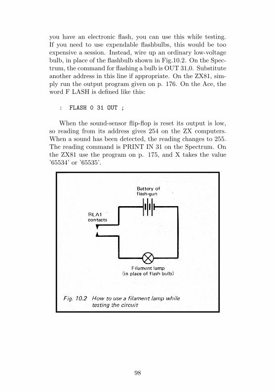
you have an electronic flash, you can use this while testing.If you need to use expendable flashbulbs, this would be tooexpensive a session. Instead, wire up an ordinary low-voltagebulb, in place of the flashbulb shown in Fig.10.2. On the Spec-trum, the command for flashing a bulb is OUT 31,0. Substituteanother address in this line if appropriate. On the ZX81, sim-ply run the output program given on p. 176. On the Ace, theword F LASH is defined like this:
: FLASH 0 31 OUT ;
When the sound-sensor flip-flop is reset its output is low,so reading from its address gives 254 on the ZX computers.When a sound has been detected, the reading changes to 255.The reading command is PRINT IN 31 on the Spectrum. Onthe ZX81 use the program on p. 175, and X takes the value’65534’ or ’65535’.
98

Programming
Controlling the photo-flash is relatively simple, and several ex-amples of possible uses for it have already been described. Hereare programs which fire the flash a short period after a soundhas been detected. This one runs on the Spectrum:
10 IF IN 31=254 THEN GO TO 10
20 PAUSE 5
30 OUT 31,0
40 PRINT "Photograph taken"
50 STOP
The PAUSE gives a delay of one tenth of a second (a twelfth ofa second in USA). With the ZX81 type in and run the combinedinput-output program given on p. 177. Then delete lines 20to 70 and type in:
20 LET X = USR 16514
30 IF X= 254 THEN GO TO 20
40 PAUSE 5
50 LET X = USR 16521
60 PRINT "PHOTOGRAPH TAKEN"
70 STOP
To program the Ace you need the word PAUSE, defined onp.147 of the Ace manual, and these three words:
: FIRE 0 31 OUT;
: LISTEN BEGIN 31 IN 1 AND UNTIL ;
: PHOTO-FLASH LISTEN 10 PAUSE FIRE ;
The figure in the definition of PHOTO-FLASH sets the lengthof the interval between detecting the sound and firing the flash.
In the programs above the micro waits in a loop until itfinds that the sensor has been triggered. Then, after a pause,the length of which you can adjust, it fires the flash. It wouldbe a useful precaution to begin the program with a routinewhich reads the sensor to make sure that you have rememberedto reset it first. If it finds that it is not reset, it displays amessage to that effect. Then when it detects that you have re-
99

set it, it goes on to the routine listed above, waiting for thesound to occur. Something of this sort will eliminate the riskof the micro firing the flash as soon as you run the program.Another refinement, especially useful if you are using the de-vice to photograph any animals which might come close to thecamera, is to insert a long pause in the program to give youtime to get away before it becomes able to respond to sound.In this event it would be a good idea to have the sensor re-set by the micro, so that the sounds of your departure do notpermanently trigger the sensor.
If you are using the micro to reset the sensor after a sound isdetected, the program must test that it has reset successfully.If it attempts to reset whilst the sound is still continuing, itwill be unsuccessful (see p. 92).
As explained on p. 10, unconnected data lines in the Aceare ’floating’ and may give either 0 or 1 when read. To readthe state of line D0 alone, we simply perform the logical ANDoperation with the data reading. If it is ANDed with 00000001, the result gives the state of line D0, irrespective of thestate of the other data lines. Thus we can read the output ofthe sound sensor by using the word:
: SOUND? 31 IN 1 AND . ;
Note that the photo-flash can have the same address for bothof its sections, for the operations of reading and writing areindependent.
PARTS REQUIRED for the PHOTO-FLASH
Resistors (carbon, 0.25W, 5% tolerance)R1, R2 100k (2 off)R3 10kR4 2M2R5 470R
CapacitorC1 100n polyester
SemiconductorQ1 ZTX300 or similar npn transistorD1 1N4001 100
100

Integrated CircuitsIC1 7611 CMOS operational amplifierIC2 74LS00 quadruple 2-input NAND gateMiscellaneousR LA1 Reed relay or other single-pole single-throw relay
operating on 6VSi, S2 Push-to-make push-button switches (2 off)MIC Crystal microphone or microphone insert8-pin IC socket14-pin IC socketSocket for connection to flash-gun3-way plugs to fit 3-way sockets on decoder board (2 off)Circuit board1mm terminal pins (8 off)Connecting wire
101
Project 11GAME CONTROL
A games controls adds a whole new aspect to computer fun.It consists of a small box with a control knob on top. As youturn the knob one way or the other, you move a ’bat’ roundthe screen, aim a ’laser gun’, steer a ’racing car’, or in someother way take a very active part in the game. You can buildand operate 2 or more of these if you wish. Another possibil-ity is to house this project in the same case as the 5-Key Pad(Project 3).
How it works
The control knob alters the setting of a variable resistor (RV1,Fig.11.1). This is wired between two 56k resistors, and thechain of resistors is connected between OV and +5V. As thewiper of RV1 is moved from one end of its track to the other,the voltage at the wiper ranges between a little over 1.25Vand a little under 3.75V. The voltage varies smoothly over thisrange. We say it is an analogue quantity. But micros are notable to accept such an input. A micro understands only twokinds of input, ’high’ and ’low’. So, IC2 converts the smoothlyvarying analogue voltage into one which alternates between’high’ and low’. This IC is driven by a clock, built up from twoNAND gates of ICI. The clock pulses cause a voltage (Vramp)inside IC2 to ramp down from about 3.75V to 1.25V. Thisactually happens in a series of 128 steps, but for all practicalpurposes it is a smooth ramp, as shown in Fig.11.2. Wheneverthe input analogue voltage is higher than Vramp, the outputof the IC is ’high’. Otherwise it is ’low’. The result is thatwe get a waveform which has a fixed frequency (one 128th ofthe clock frequency), but has a varying mark-space ratio. Asinput voltage rises the ’mark’ (or ’high’ level) decreases, andthe ’space’ (or ’low’ level) decreases. The micro is programmedto find out how much time is spent in the ’high’ or ’low’ statesand, from this information it can work out the level of the
102
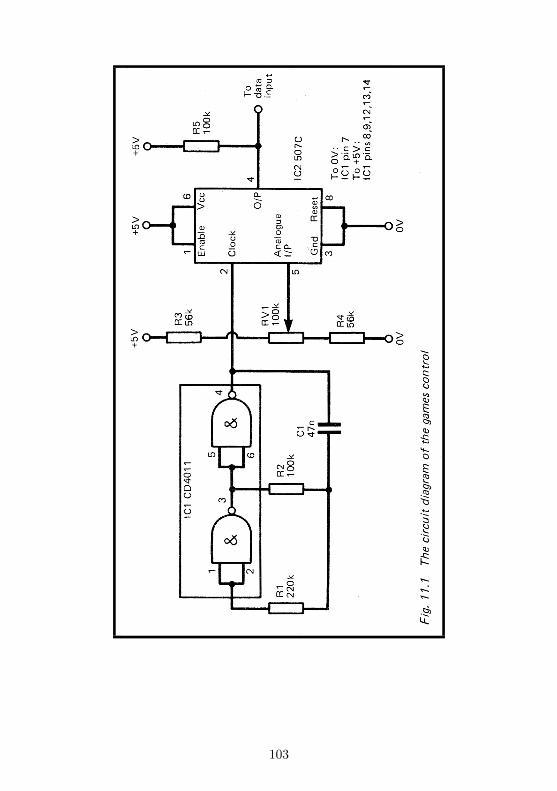
103
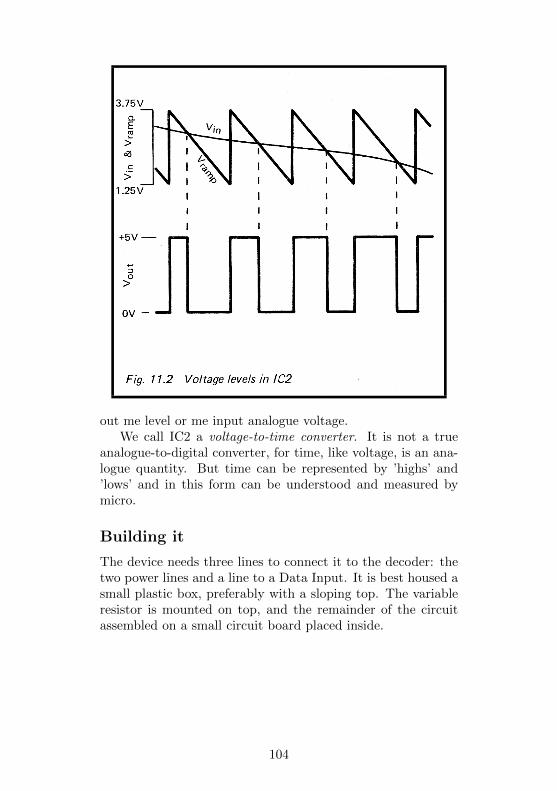
out me level or me input analogue voltage.We call IC2 a voltage-to-time converter. It is not a true
analogue-to-digital converter, for time, like voltage, is an ana-logue quantity. But time can be represented by ’highs’ and’lows’ and in this form can be understood and measured bymicro.
Building it
The device needs three lines to connect it to the decoder: thetwo power lines and a line to a Data Input. It is best housed asmall plastic box, preferably with a sloping top. The variableresistor is mounted on top, and the remainder of the circuitassembled on a small circuit board placed inside.
104
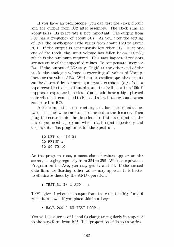
If you have an oscilloscope, you can test the clock circuitand the output from IC2 after assembly. The clock runs atabout lkHz. Its exact rate is not important. The output fromIC2 has a frequency of about 8Hz. As you alter the settingof RV1 the mark-space ratio varies from about 1:20 to about20:1. If the output is continuously low when RV1 is at oneend of the track, the input voltage has fallen below 200mV,which is the minimum required. This may happen if resistorsare not quite of their specified values. To compensate, increaseR4. If the output of IC2 stays ’high’ at the other end of thetrack, the analogue voltage is exceeding all values of Vramp.Increase the value of R3. Without an oscilloscope, the outputscan be detected by connecting a crystal earphone (e.g. from atape-recorder) to the output pins and the 0v line, with a 100nF(approx.) capacitor in series. You should hear a high-pitchednote when it is connected to IC1 and a low buzzing sound whenconnected to IC2.
After completing construction, test for short-circuits be-tween the lines which are to be connected to the decoder. Thenplug the control into the decoder. To test its output on themicro, you need a program which reads input repeatedly anddisplays it. This program is for the Spectrum:
10 LET x = IN 31
20 PRINT x
30 GO TO 10
As the program runs, a succession of values appear on thescreen, changing regularly from 254 to 255. With an equivalentProgram on the Ace, you may get 32 and 33. If the unuseddata lines are floating, other values may appear. It is betterto eliminate these by the AND operation:
: TEST 31 IN 1 AND . ;
TEST gives 1 when the output from the circuit is ’high’ and 0when it is ’low’. If you place this in a loop:
: WAVE 200 0 DO TEST LOOP ;
You will see a series of 1s and 0s changing regularly in responseto the waveform from IC2. The proportion of 1s to 0s varies
105
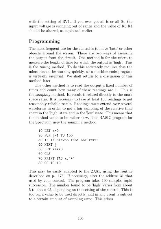
with the setting of RV1. If you ever get all is or all 0s, theinput voltage is swinging out of range and the value of R3 R4should be altered, as explained earlier.
Programming
The most frequent use for the control is to move ’bats’ or otherobjects around the screen. There are two ways of assessingthe output from the circuit. One method is for the micro tomeasure the length of time for which the output is ’high’. Thisis the timing method. To do this accurately requires that themicro should be working quickly, so a machine-code programis virtually essential. We shall return to a discussion of thismethod later.
The other method is to read the output a fixed number oftimes and count how many of these readings are 1. This isthe sampling method. Its result is related directly to the markspace ratio. It is necessary to take at least 100 readings to getreasonably reliable result. Readings must extend over severalwaveforms in order to get a fair sampling of the relative timespent in the ’high’ state and in the ’low’ state. This means thatthe method tends to be rather slow. This BASIC program forthe Spectrum uses the sampling method:
10 LET x=0
20 FOR j=1 TO 100
30 IF IN 31=255 THEN LET x=x+1
40 NEXT j
50 LET x=x/3
60 CLS
70 PRINT TAB x;"*"
80 GO TO 10
This may be easily adapted to the ZX81, using the routinedescribed on p. 175. If necessary, alter the address 31 thatused by your control. The program takes 100 samples rapidsuccession. The number found to be ’high’ varies from about5 to about 95, depending on the setting of the control. This istoo big a value to be used directly, and in any event is subjectto a certain amount of sampling error. This arises
106
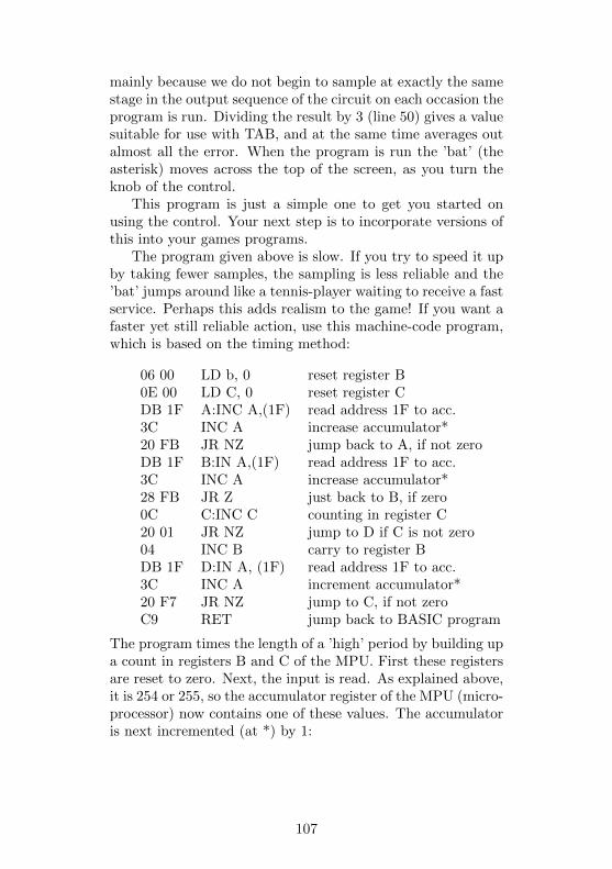
mainly because we do not begin to sample at exactly the samestage in the output sequence of the circuit on each occasion theprogram is run. Dividing the result by 3 (line 50) gives a valuesuitable for use with TAB, and at the same time averages outalmost all the error. When the program is run the ’bat’ (theasterisk) moves across the top of the screen, as you turn theknob of the control.
This program is just a simple one to get you started onusing the control. Your next step is to incorporate versions ofthis into your games programs.
The program given above is slow. If you try to speed it upby taking fewer samples, the sampling is less reliable and the’bat’ jumps around like a tennis-player waiting to receive a fastservice. Perhaps this adds realism to the game! If you want afaster yet still reliable action, use this machine-code program,which is based on the timing method:
06 00 LD b, 0 reset register B0E 00 LD C, 0 reset register CDB 1F A:INC A,(1F) read address 1F to acc.3C INC A increase accumulator*20 FB JR NZ jump back to A, if not zeroDB 1F B:IN A,(1F) read address 1F to acc.3C INC A increase accumulator*28 FB JR Z just back to B, if zero0C C:INC C counting in register C20 01 JR NZ jump to D if C is not zero04 INC B carry to register BDB 1F D:IN A, (1F) read address 1F to acc.3C INC A increment accumulator*20 F7 JR NZ jump to C, if not zeroC9 RET jump back to BASIC program
The program times the length of a ’high’ period by building upa count in registers B and C of the MPU. First these registersare reset to zero. Next, the input is read. As explained above,it is 254 or 255, so the accumulator register of the MPU (micro-processor) now contains one of these values. The accumulatoris next incremented (at *) by 1:
107
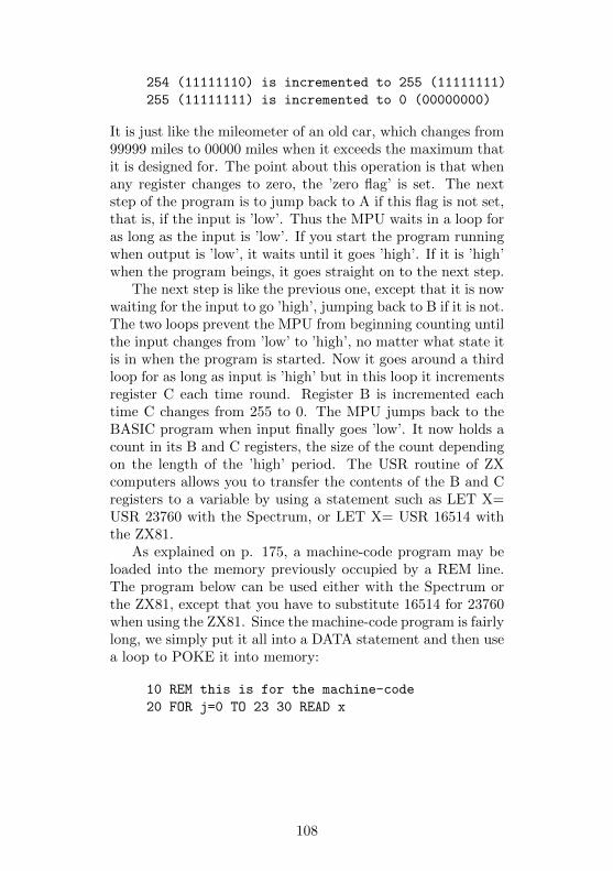
254 (11111110) is incremented to 255 (11111111)
255 (11111111) is incremented to 0 (00000000)
It is just like the mileometer of an old car, which changes from99999 miles to 00000 miles when it exceeds the maximum thatit is designed for. The point about this operation is that whenany register changes to zero, the ’zero flag’ is set. The nextstep of the program is to jump back to A if this flag is not set,that is, if the input is ’low’. Thus the MPU waits in a loop foras long as the input is ’low’. If you start the program runningwhen output is ’low’, it waits until it goes ’high’. If it is ’high’when the program beings, it goes straight on to the next step.
The next step is like the previous one, except that it is nowwaiting for the input to go ’high’, jumping back to B if it is not.The two loops prevent the MPU from beginning counting untilthe input changes from ’low’ to ’high’, no matter what state itis in when the program is started. Now it goes around a thirdloop for as long as input is ’high’ but in this loop it incrementsregister C each time round. Register B is incremented eachtime C changes from 255 to 0. The MPU jumps back to theBASIC program when input finally goes ’low’. It now holds acount in its B and C registers, the size of the count dependingon the length of the ’high’ period. The USR routine of ZXcomputers allows you to transfer the contents of the B and Cregisters to a variable by using a statement such as LET X=USR 23760 with the Spectrum, or LET X= USR 16514 withthe ZX81.
As explained on p. 175, a machine-code program may beloaded into the memory previously occupied by a REM line.The program below can be used either with the Spectrum orthe ZX81, except that you have to substitute 16514 for 23760when using the ZX81. Since the machine-code program is fairlylong, we simply put it all into a DATA statement and then usea loop to POKE it into memory:
10 REM this is for the machine-code
20 FOR j=0 TO 23 30 READ x
108
40 POKE 23760+j,x
50 NEXT j
60 DATA 6, 0, 14,0, 219, 31, 60, 32, 251, 219, 31,
60, 40, 251, 12, 32, 1, 4, 219, 31, 60, 32, 247,
201
70 LET x=USR 23760
80 IF x<10 THEN GO TO 70
90 LET x=INT (x/250)
100 CLS
110 PRINT TAB x;"*"
120 GO TO 70
If you are not using address 31, substitute the correct valuethree times in line 60, in place of all the 31s. When youhave run this program once, the whole of the text in the REMwill have been replaced by various symbols, for that section ofmemory now holds the machine-code program. You can thendelete lines 20 to 60 in order to make space for your games pro-gram. Running this program as it stands produces the sameresult as the earlier program, but it is much faster. If you findthat the ’bat’ does not move far enough to the right, reduce thevalue of the divisor in line 90. This fast program occasionallypicks up very brief and spurious ’high’ pulses coming from theIC, and returns with a count of 1 or 2. Line 80 is there so thatsuch pulses are ignored.
A machine-code program similar to the above would workon the Jupiter Ace too, for this also has a Z80 as its MPU. Youneed to change the INC A codes to AND 1. The code for thisoperation is E6 01. Enter this in place of 60 at three pointsin the program. The program may be placed in the parameterfield of a word, as described on p.147 on the Ace’s manual.
FORTH runs so much faster than BASIC that there is littleto gain by using machine-code. Here are some FORTH wordswhich will display a moving ’bat’ on the Ace, using the timingmethod:
: HIGH? BEGIN 31 IN 1 AND UNTIL ;
: LOW? BEGIN 31 IN 1 AND WHILE 1+ REPEAT ;
: BAT INVIS 4 HIGH? LOW? SWAP / 0 SWAP CLS
AT ." *" ;
109

: PLAY 200 0 DO BAT LOOP ;
HIGH uses BEGIN . . . UNTIL, so waits until the input condi-tion is true (=1). By contrast, LOW? uses BEGIN ... WHILE,so waits until input is false (=0). In the word BAT, HIGH?waits for input to become ’high’. Then LOW? waits for it tobecome ’low’ again, and increments the top of stack while doingso. Then the count is divided by 4, and the ’bat’ is displayedon the top line of the screen at the corresponding position.Note that a low result is obtained if input is ’high’ when theprogram is started. After that, the program keeps pace withthe changing input. If the ’bat’ moves too little, change the 4of the BAT definition to 3. If it moves too much, change it to5. The definition could be adapted to floating-point numbersto obtain the required range of the ’bat’ with greater precision.
PARTS REQUIRED for the GAMES CONTROL
Resistors (carbon, 0.25W, 5% tolerance)R1 220kR2, R5 100k (2 off)R3, R4 56k (2 off)RV1 100k variable potentiometer
CapacitorC1 47n polyester
Integrated CircuitsIC1 CD4011 CMOS quadruple 2-input NAND gateIC2 507C voltage-to-timer converter
MiscellaneousCase suitable for mounting control potentiometerKnob for RV1, suitable for use in gamesCircuit board1mm terminal pins (6 off)8-pin IC socket14-pin IC socket3-way socket to fit 3-way plug of decoder board
110

Project 12RAIN DETECTOR
The remaining projects in the book make up a weather stationseries. They can all be plugged into the decoder and operatedtogether to record certain aspects of the weather. These areeasy projects and are not precision instruments, but they giveenough information to allow the micro to try to predict whatthe future weather is likely to be. Although these last sixprojects are concerned with meteorology, many of them haveseveral other useful applications.
This project is the simplest in the whole book. It tells youwhen it is raining. Not only does this allow the micro to keepa record of the number of rainy days, or the number and dura-tion of rain showers, but it has other uses around the home.Onwashdays it is handy for detecting when it starts to rain. Ifthe Bleeper (Project 5) is connected at the same time, andis located in the kitchen (or beside the TV set?), the microcan sound a warning that the washing must be taken in. Theproject also detects when water rises above a given level. Inconjunction with the micro it can warn you when the bath isoverflowing, or when the well is running dry.
How it works
The base current to the transistor (Q1, Fig.12.1) comes byway of a probe. This consists of strips of conducting mate-rial placed close together. Their distance apart is such thatraindrops are able to bridge the gap. A single raindrop willallow sufficient conduction to occur to turn on the transistor.The result of this is that the level at the Data Input falls from’high’ to ’low’. F ig.12.2 shows an easy way to make the probefrom a scrap of strip-board.
Building it
Two small scraps of strip-board are required, one for the
111
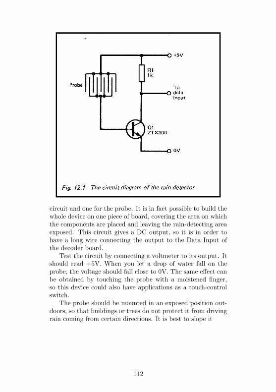
circuit and one for the probe. It is in fact possible to build thewhole device on one piece of board, covering the area on whichthe components are placed and leaving the rain-detecting areaexposed. This circuit gives a DC output, so it is in order tohave a long wire connecting the output to the Data Input ofthe decoder board.
Test the circuit by connecting a voltmeter to its output. Itshould read +5V. When you let a drop of water fall on theprobe, the voltage should fall close to 0V. The same effect canbe obtained by touching the probe with a moistened finger,so this device could also have applications as a touch-controlswitch.
The probe should be mounted in an exposed position out-doors, so that buildings or trees do not protect it from drivingrain coming from certain directions. It is best to slope it
112
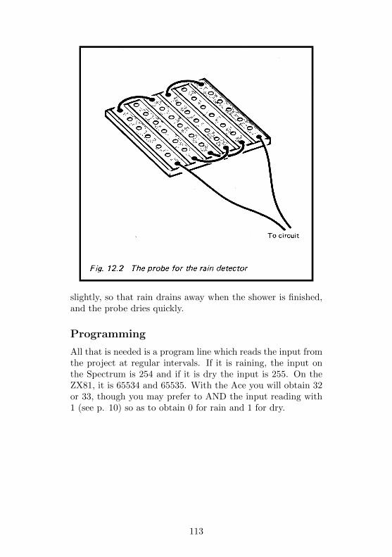
slightly, so that rain drains away when the shower is finished,and the probe dries quickly.
Programming
All that is needed is a program line which reads the input fromthe project at regular intervals. If it is raining, the input onthe Spectrum is 254 and if it is dry the input is 255. On theZX81, it is 65534 and 65535. With the Ace you will obtain 32or 33, though you may prefer to AND the input reading with1 (see p. 10) so as to obtain 0 for rain and 1 for dry.
113

PARTS REQUIRED for the RAIN DETECTOR
ResistorR1 1k
SemiconductorQ1 ZTX300 or almost any npn transistor
MiscellaneousStripboard for circuit and probe (small scrap)3-way socket to fit 3-way plug on decoder boardConnecting wire
114
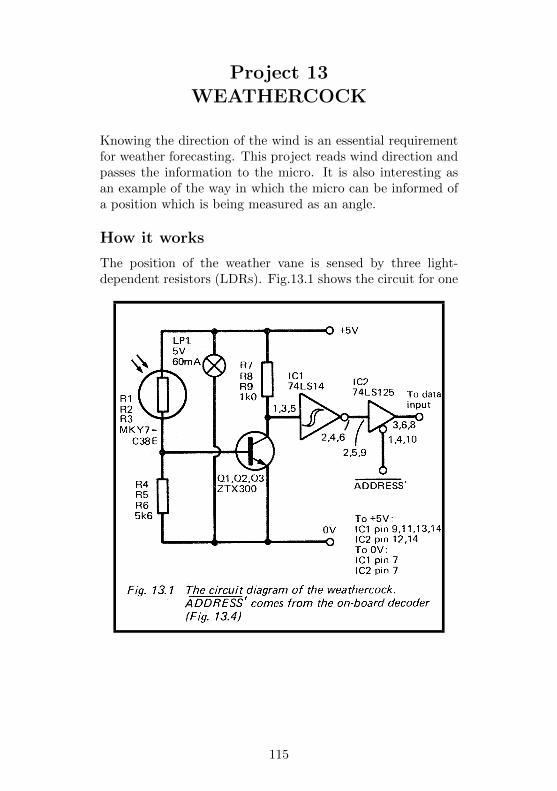
Project 13WEATHERCOCK
Knowing the direction of the wind is an essential requirementfor weather forecasting. This project reads wind direction andpasses the information to the micro. It is also interesting asan example of the way in which the micro can be informed ofa position which is being measured as an angle.
How it works
The position of the weather vane is sensed by three light-dependent resistors (LDRs). Fig.13.1 shows the circuit for one
115
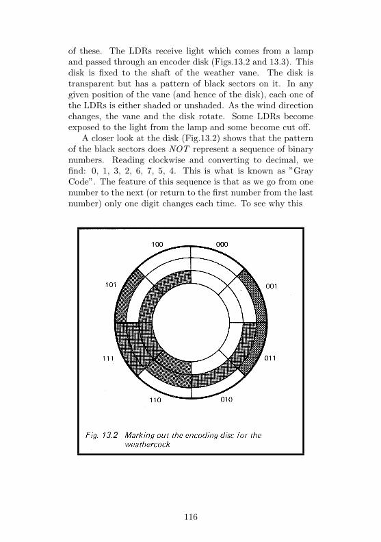
of these. The LDRs receive light which comes from a lampand passed through an encoder disk (Figs.13.2 and 13.3). Thisdisk is fixed to the shaft of the weather vane. The disk istransparent but has a pattern of black sectors on it. In anygiven position of the vane (and hence of the disk), each one ofthe LDRs is either shaded or unshaded. As the wind directionchanges, the vane and the disk rotate. Some LDRs becomeexposed to the light from the lamp and some become cut off.
A closer look at the disk (Fig.13.2) shows that the patternof the black sectors does NOT represent a sequence of binarynumbers. Reading clockwise and converting to decimal, wefind: 0, 1, 3, 2, 6, 7, 5, 4. This is what is known as ”GrayCode”. The feature of this sequence is that as we go from onenumber to the next (or return to the first number from the lastnumber) only one digit changes each time. To see why this
116
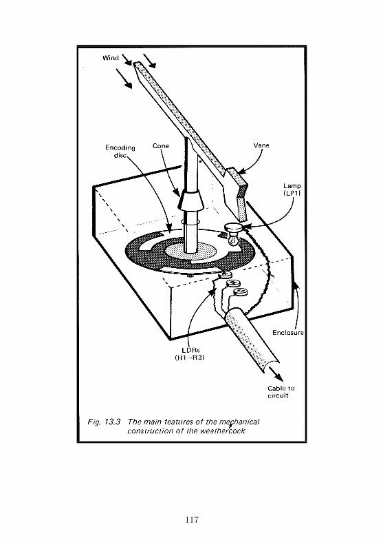
117
is important let us look at what would happen if we began thesequence with 0, 1, 2, ... . The first change would be:
0 0 0
changing to 0 0 1
This creates no problems and this change is found in the Graysequence. But the second change could be troublesome:
0 0 1
changing to 0 1 0
This would be all right if both digits changed at exactly thesame instant. In a piece of equipment such as this it is veryunlikely that the LDRs are so precisely arranged and theirresistances are so exactly matched that each will respond inan identical manner. They will not all change at the sameinstant. If the middle digit changes before the right-hand digit,we get an intermediate stage showing 011. We get the same ifthe right-hand digit changes first. Instead of getting 0, 1, 2,. . . as the disk rotates, we get 0, 1, 3, 2 . . The 3 is onlythere briefly, but there would be time for the micro to take areading and obtain a false result. The Gray code overcomesthis problem, since only one digit changes each time.
Building the vane
Fig.13.3 shows the general features of a typical Weathercock.Exactly how you construct yours depends on what materialsand tools you have available and on your skill in making sucha device. It is often possible to adapt a ready-made weath-ercock. Such instruments are obtainable cheaply from storesselling educational equipment. Often they are made from plas-tic and while these cheaper models are generally less durablethan those intended for serious use, they are usually easier toadapt. The disk is made from clear transparent plastic. Asheet of thick acetate film can be used, and may be painted byusing a black marker pen (felt-tip spirit pen). Alternatively,the sectors may be cut out from black PVC insulating tapeand stuck on the disk. In order that the readings indicate themajor points of the compass (N. NE, E, SE etc), the LDRs areplaced so
118
that the centre of each sector lies over the line of LDRs whenthe vane is aligned with the main compass points.
For clarity, Fig.13.3 shows the disk several centimetres abovethe LDRs, but it is much better if the gap is small and the diskalmost touches them. The lamp should be mounted a few cen-timetres above the disk, so that its light spreads fairly equallyto all three LDRs. Leads are taken from each LDR back tothe main circuit which is to be housed in a small case near tothe micro.
Fig.13.3 shows a way of preventing rainwater from runningdown the shaft into the mechanism. The cone deflects it on tothe top surface of the light-proof box. It is not essential forthe hole where the shaft enters the enclosure to be absolutelylight-proofed, though a collar around the shaft helps to preventlight from scattering toward the LDRs.
The circuit uses three lines of the data bus (lines DO toD2). ICI has three-state outputs (p. 160) which are enabledby a low from the address decoder circuit.
Addressing
As explained for Project 2 (p. 21), the addressing of thisproject is not completely provided for by the decoder (p. 158).If you want to connect only this project to the micro, you cando as suggested on p. 21: wire the ADDRESS output terminalof the decoder (Fig.D.1) to the ADDRESS’ input terminal ofthe Weathercock detector (Fig.13.1). It can then be addressedusing any one of the addresses in Table D.2.
If you would like to have other projects connected at thesame time as this project, you need to add a decoder to thisproject. You will probably want to have several weather-station projects working at once, so make sure they all areat different addresses. To keep the wiring as simple as pos-sible, the decoder uses only lines A5 and A6 (Fig.13.4). Asexplained on p. 21, it responds to two addresses, which are 5Fand DF or 7F and FF.
119
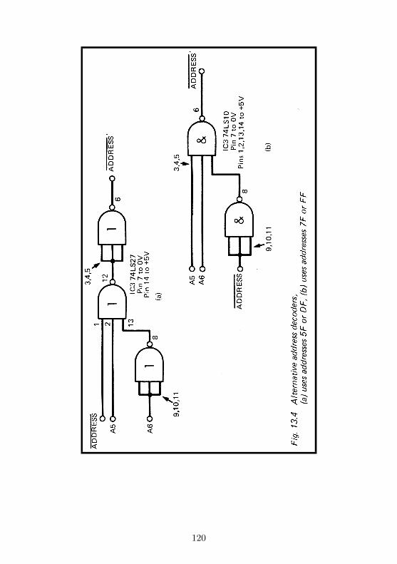
120
Building the circuit
The device is to be plugged on to one of the 10-way plugs of thedecoder (p. 172). It requires 9 lines: the two power lines, threedata lines, 2 address lines and the ADDRESS line. It also wiresfrom the negative ends of the three LDRs. The type of LDRrecommended is small, but any LDR of small diameter can heused instead. Larger types can be used if these are the onlyones available, but to use these requires that the disk must alsobe made larger. If the LDRs are not of the type specified andhave a higher or lower resistance range, it may be necessary tosubstitute resistors of a different value for R4-R6.
It is best to build and test the circuit for one LDR first.It is then easy to check that the correct resistance is beingused for R4-R6, before proceeding with the remainder of theconstruction. When all is finished, temporarily wire the bufferenable input (IC2, pins 1, 4 and 10) to 0V to enable the out-puts. Slowly rotate the disk to measure the output of eachbuffer with a voltmeter. Fig.13.2 shows what results to ex-pect, where 0 represents a ’low’ output (less than 0.8V) and 1represents a ’high’ output (more than 2V). Assuming that allis correct, test all wires going to the decoder board to checkthat there are no short-circuits between any pair of them.
Programming
All that is required is to read the data input. This circuitleaves the top 5 data lines unconnected, so they each take thevalue 1. With zero input from the Weathercock, the data busreads 1111 1000, which gives 248 in decimal on the Spectrum.A simple program such as:
10 LET x= IN 95
20 PRINT x
results in a number between 248 and 255 being displayed. Youthen have to write 8 program lines to interpret this reading.This is one of them:
30 IF x-248 THEN LET wind$="North"
121

On the Ace, it is best to AND the input with 7, so as toobtain a number between 0 and 7. A suitable word definitionis:
: WIND? 95 IN 7 AND . ;
In the listings above we are assuming that the weathercock isaddressed at 5F (hexadecimal, or 95 in decimal). If you areusing another address modify the lines accordingly.
You may be able to use the wind direction to predict theweather. What the prediction will be depends very much onyour locality. It may also depend on other features of the cur-rent weather measured by some of the other projects. As wellas reading direction, you can use the weathercock to detectchanges in the wind direction over a period of several hours.If the wind is veering, that is to say, changing direction in aclockwise direction, possibly indicates an approaching depres-sion, with the likelihood of low cloud and rain.
Another aspect is the steadiness of wind direction. If theweathercock is read every minute and it is found that the direc-tion is changing frequently, this can be another clue to whatfuture weather is likely to be. There are several books onweather which will help you work out your predictions. Youmay also be able to program the micro to work these out foryou.
PARTS REQUIRED for the WEATHERCOCK
Resistors (carbon, 0.25W, 5% tolerance, except R1-R3)R1-R3 MKY7C38E or similar light-dependent resistor(preferably small) (3 off)R4-R6 5k6 (but see text) (3 off)R7-R9 1k0 (3 off)
SemiconductorsQ1-Q3 ZTX300 or similar npn transistor (3 off)
Integrated CircuitIC1 74LS14 Hex Schmitt triggerIC2 74LS125 quadruple bus buffer gate with threestate output
122

MiscellaneousLP1 5V 60mA filament lampSocket for LP114-pin IC sockets (2 off, if on-board decoder used)10-way socket to fit 10-way plug on decoderCircuit board1 mm terminal pins (14 off)Materials for the mechanical parts
Parts for Alternative Address Decoders(a) IC3 74LS27 triple three input NOR gate(b) IC3 74LS10 triple three input NAND gate
123
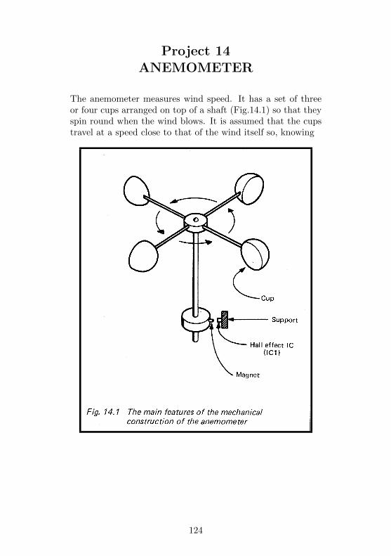
Project 14ANEMOMETER
The anemometer measures wind speed. It has a set of threeor four cups arranged on top of a shaft (Fig.14.1) so that theyspin round when the wind blows. It is assumed that the cupstravel at a speed close to that of the wind itself so, knowing
124

the radius of the assembly and the rate of rotation, we estimatewind speed. In effect, the circuit of this project is a tachometer,a circuit to measure rate of rotation. The circuit could beadapted to measure the rate of rotation of other machinery.
How it works
Figure 14.1 shows that there is a wheel at the base of theshaft of the anemometer. This rotates at the same rate asthe cups. The wheel is made from non-magnetic material suchas plastic or wood. It carries a small permanent bar magnetat one point on its circumference. The magnet is arrangedwith one of its poles protruding slightly. As the wheel rotates,the magnet is carried past an IC which is mounted to oneside of the rotating assembly. This is a Hall Effect IC. TheHall Effect occurs when a piece of semiconducting materialis placed in a magnetic field. Those who remember learningFleming’s Left Hand Rule in physics lessons will know thatthere is an interaction between a current and a magnetic field.In Fig.14.3 a current is passed along a slice of semiconductor.The moving electrons are deflected to one side when a strongmagnetic field is present. The result is a potential differencebetween the two sides of the conductor. This is detected andamplified by circuits within the IC. The outputs of IC1 arenormally at about 2V. When a magnet is held close to the101 the voltage at one output rises slightly and the other falls.The operational amplifier IC2 compares these voltages. Whenthey are equal (or nearly equal) its output is ’low’. Whenthe voltages are unequal (i.e. when a magnet is near), theoutput of IC2 rises sharply to +5V. This quickly switches onQ1. The voltage at the input of the counter (IC3) falls sharply,triggering the counter. Thus the counter is incremented everytime the magnet passes close to 101.
IC3 is wired as a divide-by-16 counter, so its D outputchanges at one-sixteenth of the rate at which the anemometeris rotating. This rate is measured by the micro, which thencalculates the wind speed.
125
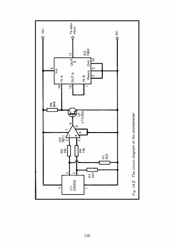
126
Building it
Unlike most of the interfaces in this book, the whole circuitis best located close to the sensor. The output from IC3is a slowly changing one, making it suitable for transmissionalong a relatively lengthy line to a Data Input of the decoder.The circuit requires three connections to the decoder: the twopower lines and a wire to a Data Input.
The circuit is to be housed in a weatherproof case. It maybe convenient to mount ICI on the outside of the case. Leads tothis should be covered with melted paraffin wax or a weather-proofing and water-proofing compound to eliminate the possi-bility of short circuits.
The anemometer assembly is easy to build. Empty foodcartons may be used for the cups and the cross-pieces can bemade from stiff wire. The main essential is that the assemblyrotates freely. Its diameter should be about 30cin or possiblya little more. The wheel which carries the magnet can becut from wood, plastic or a large cork stopper. A suitablemagnet is usually sold with the Hall Effect IC. Take care whenmounting the magnet and the IC that there is no danger of thetwo coming into contact as the assembly rotates, particularlyin high winds. On the other hand, the end of the magnet needsto pass within about linin of the centre of the IC in order togenerate a sufficiently great voltage difference.
Build the entire circuit, then connect it to a +5V powersupply for testing. Connect a voltmeter to one of the outputsof IC1. Rotate the anemometer slowly and note the rise orfall of voltage as the magnet passes the IC. Now transfer thevoltmeter to the output of IC2. The output should be OV,but rises sharply to +5V whenever the magnet passes IC1.If this does not happen, the polarity of the magnet is wiong;remove it from the wheel and replace it the other way round.Connect the voltmeter to the D output of IC3. The outputshould rise to ’high , fall to ’low’ and rise to ’high’ once forevery 16 rotations of the anemometer.
The output from D changes at a slow rate so the cablebetween the interface and the decoder board can be severalmetres long. This allows the device to be mounted as high as
127
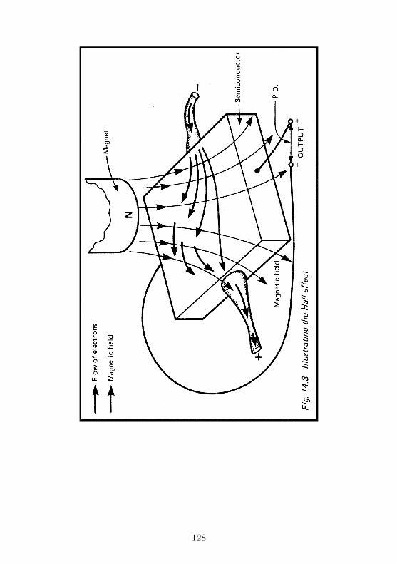
128
possible above ground so as to expose it to the full speed ofthe wind.
Programming
We require a program which measures the length of pulsescoming from the D output. The machine-code program on p.107 is suitable for use with the ZX81 and Spectrum. However,the pulse rate is slow, so a BASIC program will generally beadequate. With the Ace, use the word definitions on p. 109.
By turning the anemometer by hand at a known rate, itis possible to relate the value obtained to a given number ofrevolutions per second. Turn the anemometer by hand (about1 revolution per second) for 20 or so revolutions. Count thenumber of revolutions exactly and also measure the time taken.Calculate the rate in revolutions per second. As the sametime run the timing program to see what value is obtained.This gives the figure which corresponds to the rate of turning.Repeat this several times to obtain an average result for usein calculations later. Remember that the figure obtained isinversely related to the rate of rotation. For example, doublingthe rotation rate halves the figures.
Assuming that the cups of the anemometer are moving withthe same speed as the wind, the wind speed is:
S = 2 × πr ×R× 3600 ÷ 100000
Where S is the wind speed in kilometres per hour, R is therate of rotation in revolutions per second, and r is the radiusof the anemometer assembly in centimetres. The symbol π hasits usual value 3.1412, so the equation can be simplified to:
S = 0.226 × r ×R
The corresponding equation for British units is:
S = 0.357 × r ×R
where S is in miles per hour, R is revolutions per second and ris in inches. Either of these equations can be used in a programto calculate the wind speed, given the rate of rotation. For
129

example, if the interface is giving 1 count per second, this cor-responds to a rotation rate (R) of 16 revolutions per second.If the radius of the anemometer is 15cm, the wind speed is:
S = 0.226 × 15 × 16 = 54km/h
With a similar anemometer with radius of 6 inches, the windspeed is:
S = 0.357 × 6 × 16 = 34mph
The anemometer circuit can easily cope with rotations of dou-ble this rate so can register winds of 100km/h or more.
PARTS REQUIRED for the ANEMOMETER
Resistors (carbon, 0.25W, 5% tolerance)R1, R2 2k2 (2 off)R3, R4 10k (2 off)R5 6k8
SemiconductorsQ1 ZTX300 or similar npn transistor
Integrated CircuitsIC1 634SS2 Hall Effect IC (complete with magnet)IC2 7611 CMOS operational amplifierIC3 7493 4-bit binary counter/divider
MiscellaneousCircuit board8-pin IC sockets (2 off, including one for IC1)14-pin IC socketlmm terminal pins (7 off)3-way socket to fit 3-way plug of decoder board Materials
for making anemometer assemblyConnecting wire
130

Project 15THERMOMETER
Although this project is part of the weather-station series, ithas many other applications. It may be used indoors to mea-sure room temperatures, or perhaps the temperature of pho-tographic solutions. It can be used to detect excessive temper-ature as part of a domestic fire alarm system.
How it works
The circuit works in much the same way as that of the GamesControl (Project 11). Instead of the variable potentiometerused in that circuit we have a variable resistor of another kind(fig.15.1). This is a thermistor, the resistance of which variessignificantly with temperature. The thermistor used in thiscircuit (Fig.15.1) has what is known as negative temperaturecoefficient, which means that, over its usual working range, itsresistance decreases as its temperature increases. An increas-ing temperature causes the resistance of the thermistor to fall,resulting in a falling potential at point A and a falling analoguevoltage at the input of IC2. As explained under project 11, thewaveform of the output of IC changes (see Fig.11.2), and thechange can be measured by the micro.
Building it
Normally the thermistor is located outdoors. For use in weatherrecording, the best place is inside a meteorological screen. Thisshades it from direct sunlight yet allows air to circulate freelyaround it. If you do not have such a screen, mount it in aplace where direct sunlight can not reach it and where air cir-culation is good. It should be several centimetres away fromany surface such as a wall or fence, otherwise it may take thetemperature of the wall or fence, instead of that of the air. Ifit is in the open, protect it from rain, for this may cause apartial short-circuit, and readings will be incorrect. One
131
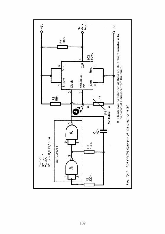
132
method of waterproofing is to melt some paraffin wax and todip the thermometer in the wax to coat it. Another method isto mix a quantity of epoxy resin adhesive (e.g. Araldite) andcoat it with this.
The rest of the circuit is built in a small case, located closeto the micro. It needs three wires to connect it to the micro:the two power lines and a wire to a Data Input. The circuitdoes not require any address decoding except that provided bythe Decoder.
When the circuit is ready, it may be tested in the sameway as the Games Control (see pp. 104-6). You can try theeffects of various temperatures by immersing the thermistor inwarm water or in water containing melting ice cubes. In suchextremes the output of IC2 should never be continuously ’high’or ’low’. If this condition is found, replace R3 by a resistor ofdifferent value, or possibly wire an additional resistor betweenR4 (the thermistor) and the 0V line. Exactly what you mayneed to do depends on the characteristics of the thermistor youare using and the range of temperature over which you requireit to operate.
Calibration and programming
The simplest method of programming is to read the outputfrom the circuit many times and count how many ’high’s areobtained. This is the sampling method referred to on p. 106.With the ZX81 and Spectrum we may use a very similar pro-gram to that given there, except that it is feasible to take manymore samples to obtain a more reliable result. Line 20 mightbe amended to take, say, 500 samples instead of only 100. Theadditional time required for this does not matter in this ap-plication. Lines 50-70 are not applicable, though somethingsimilar could be employed to plot a graphics ’thermometer’ onthe screen. Instead, type in this line: 50 PRINT x.
Having obtained a value x which varies in proportion totemperature, the next step is to calibrate the thermometer.Place the thermistor in a glass of water containing meltingice-cubes. Stir occasionally, and allow at least 5 minutes for
133
the thermistor to take up the temperature of the water. Thisis close enough to 0°C(32°F).
Run the program several times and find an average value forx. Results should be in the region of 20 to 50. If the count stillseems to be decreasing, wait a while longer, for the thermistorhas not cooled fully. If the ice cubes melt completely, replacethem. Now repeat the procedure, but using a glass full of warmwater at say 30°C (or say 90°F). Choose a temperature whichis a little above the upper end of the range which you want tomeasure. You will need a thermometer to find out what theexact temperature is. Readings should now be at the upperend of the range, over 300 at least.
If the difference between the lowest and highest readings istoo small you will not be able to obtain an accurate result. Inthis event you may need to replace R3, or wire in an additionalresistor, as already mentioned.
Let us suppose that you obtained a reading of x1 at 0 °Cand x2 at T °C. The formula for converting the reading x atany temperature t is:
t = (x− x1) × Tx2−x1
For example, if the count is 40 at 0°C and 420 at 30°C, then acount of 150 is equivalent to a temperature of:
t = (150 − 40) × 30420−40
= 90 × 30/380 = 7.1°C
The same formula may be used on the Fahrenheit scale,except that having calculated t, you add 32 degrees to it.
As a program line, given the values mentioned above, theformula becomes:
60 LET t=(x-40)*30/380
On the Ace, we can use a set of words similar to those usedwith the Game Control:
134
: HIGH? BEGIN 31 IN 1 AND UNTIL ;
: LOW? BEGIN 31 IN 1 AND WHILE REPEAT ;
: COUNT HIGH? LOW? 0 500 1 DO 31 IN 1 AND
IF 1+ THEN LOOP ;
: TEMP 30 COUNT 33 4 302 / . ;
’HIGH’ is as given before, but LOW? does not act as a counter.The word COUNT does this but waits for output to go ’high’and then ’low’ before it starts. It then takes 500 sample read-ings and counts those which are high. This extends over severaloutput pulses from the circuit. It finishes with this count ontop of stack. TEMP performs the calculation. This definitionis based on a calibration count of 33 at 0°C and 335 at 30°C.(N.B. 302 = 335-33). This word prints out the temperature asan integer. You could adapt the definition to work in floating-point so as to obtain a more precise result.
As well as reading temperature at a given instant, the microcan be programmed to take readings at regular intervals andrecord them in memory. They could then be displayed daily oron demand and a table could be printed out. If the readingsare taken frequently enough it is easy to program the micro toprint out the maximum and minimum daily temperatures too.
PARTS REQUIRED for the THERMOMETER
Resistors (carbon, 0.25W, 5%tolerance)R1 220kR2, R5 100k (2 off)R3 56kR4 VA1056S rod thermistor, or any negative temperature
coefficient thermistor having resistance about 47k at 25°C (discand bead types equally suitable)Capacitor
Cl 47n polyesterIntegrated Circuits
IC1 CD4011 CMOS quadruple 2-input NAND gateIC2 507C voltage-to-time converter
135

MiscellaneousSuitable housing for thermistorCase for circuitCircuit board1mm terminal pins (5 off)8-pin IC socket14-pin IC socket3-way socket to fit 3-way plug of decoder boardConnecting wire
136
Project 16BAROMETER
A barometer measures the pressure of the atmosphere. It isalmost essential for forecasting the weather. The approachof depressions or anticyclones is announced by a fall or risein pressure. This gives us advance warning of what kind ofweather to expect. The rate of change of pressure, tells us howsoon we may expect the weather to change. In addition, rapidchanges of pressure mean strong winds, while slow changes orno changes at all are associated with calm weather.
Devices for measuring atmospheric pressure electronicallyare usually very expensive. Indeed, an IC which does this maycost about as much as a ZX81! This project is far cheaper andalthough it does not give an accurate reading, it is the changeswhich are important. It is much less important to know whatthe exact pressure is. So this device is a useful one for the forecaster.
How it works
The barometer is based on an extremely simple idea which isoften featured in books of science projects for young people(Fig.16.1). The inverted tube contains air. As atmosphericpressure increases, the air inside the tube becomes more com-pressed and the water rises up inside the tube. When pressurefalls again, the air expands and the water level falls. Pressureis measured by measuring the level of the water. Unfortu-nately this apparatus has one big snag as a barometer. Airexpands when heated. If the temperature increases, the waterlevel falls, even though the atmospheric pressure may not havechanged. It is possible to allow for the change in temperatureby working out how much it would alter the volume of the air.This is too much trouble to be bothered with for the simplebarometer of Fig.16.1, but if we make a similar barometer andattach it to a micro, the micro can do all the working out forus!
137
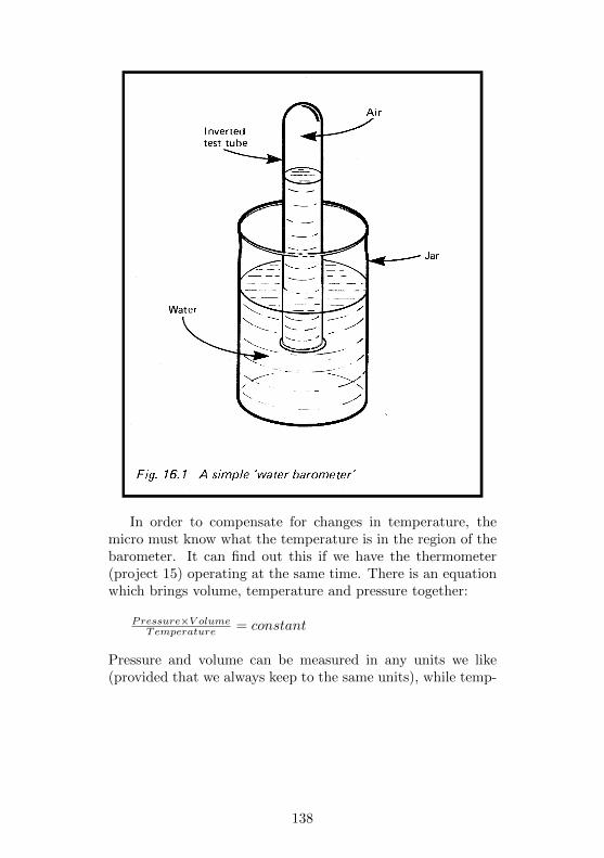
In order to compensate for changes in temperature, themicro must know what the temperature is in the region of thebarometer. It can find out this if we have the thermometer(project 15) operating at the same time. There is an equationwhich brings volume, temperature and pressure together:
Pressure×V olumeTemperature = constant
Pressure and volume can be measured in any units we like(provided that we always keep to the same units), while temp-
138

erature must be measured in kelvin. To work out any temper-ature in kelvin, just take the temperature on the Celsius scale(sometimes wrongly cally the Centigrade scale) and add 273.
If we measure pressure, volume and temperature of the airinside the barometer on two separate occasions, and since thecalculated result is a constant we can say:
1st Pressure × 1st V olume1st Temperature = 2nd Pressure × 2nd V olume
2nd Temperature
or, rearranging the above:
2nd pressure =1st pressure × 1st V olume
2nd V olume × 2nd Temperature1st Temperature
We use an ordinary barometer to measure the 1st pressurewhen we first take a reading with our home-made barometer.As the same time we measure 1st temperature and the 1stvolume. Some time later we (or the micro) measure 2nd volumeand 2nd temperature and can then calculate the 2nd pressure.Project 15 measures temperature, while this project measuresvolume. The micro then calculates the pressure.
In this project, the air is contained in a plastic or glasstube (Fig.16.2). The top end of the tube has a tap to makeit airtight. Its bottom end dips into a small jar containingwater. The water has been made black by having had IndianInk added to it. The most extreme changes of pressure andtemperature make the water level move over a range of about2cm.
In the region over which the water level will move, the tubeis covered with black insulating tape, except for slits on oppo-site sides of the tube. Light from a small lamp passes throughone slit, across the tube and out through the other slit. It ispicked up by a light-dependent resistor (LDR). The resistanceof this varies according to the brightness of the light (p. 66).Since the water is black, it cuts off a varying amount of light,depending on its level. In this way, changes in water level areturned into changes in electrical resistance. In the prototype ofthis Project the LDR resistance was 940ohms when the waterwas at its lowest level but increased to 1700
139
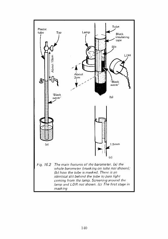
140

ohms when the water had completely cut off the light. For thesame reasons as are given on p. 67, changes in the resistance ofthe LDR (Fig.16.3) affect the voltage at point A. This changingvoltage is fed to IC2, which is a voltage-to-time converter. Theway this works is explained on p. 102. The overall effect is thatas pressure increases, the volume decreases, the voltage at Aincreases and the waveform from IC2 spends proportionatelymore time in the ’high’ state. If the micro is programmed tomeasure this time, the figure obtained is greater.
It is important to realize that the response of this deviceis far from linear. That is to say, equal increases in pressuredo not bring about equal increases in the value found by themicro. However, the figure the micro obtains can be used toassess whether pressure has increased or decreased over thepast hours or days, and whether it is changing slowly or quickly.
Building it
First of all build the barometer itself. There are several waysof doing this. The tube may be of glass, though clear plastictubing such as is sold for aquarium aerating systems is verysuitable. A tap to fit the tubing may also be obtained from ashop specializing in aquaria. The tube may be held straightby stapling it to a strip of wood. This is mounted verticallyon a wooden base. The water container can be a small plasticor glass bottle such as is used to hold medicine tablets.
Prepare two strips of black insulating tape about 2cm longand wide enough to leave two gaps about 1.5mm wide whenthey are fixed on the tube (Fig.16.2c). Wind two other stripsaround the tube about 2cm apart, as in Fig.16.2b. This leavestwo slits about 2 cm long and 1.5 mm wide on opposite sidesof the tube. Measure the length of the slit and the distance be-tween the tap and the top of the slit to the nearest millimetre.Mount a small filament lamp to one side of the tube, about1cm from it. The lamp should be housed in a small box, madefrom thin white card, to keep light from reaching the LDRdirectly, and to reflect as much light as possible toward
141
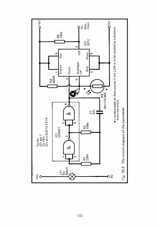
142
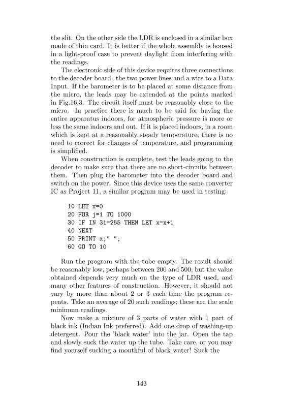
the slit. On the other side the LDR is enclosed in a similar boxmade of thin card. It is better if the whole assembly is housedin a light-proof case to prevent daylight from interfering withthe readings.
The electronic side of this device requires three connectionsto the decoder board: the two power lines and a wire to a DataInput. If the barometer is to be placed at some distance fromthe micro, the leads may be extended at the points markedin Fig.16.3. The circuit itself must be reasonably close to themicro. In practice there is much to be said for having theentire apparatus indoors, for atmospheric pressure is more orless the same indoors and out. If it is placed indoors, in a roomwhich is kept at a reasonably steady temperature, there is noneed to correct for changes of temperature, and programmingis simplified.
When construction is complete, test the leads going to thedecoder to make sure that there are no short-circuits betweenthem. Then plug the barometer into the decoder board andswitch on the power. Since this device uses the same converterIC as Project 11, a similar program may be used in testing:
10 LET x=0
20 FOR j=1 TO 1000
30 IF IN 31=255 THEN LET x=x+1
40 NEXT
50 PRINT x;" ";
60 GO TO 10
Run the program with the tube empty. The result shouldbe reasonably low, perhaps between 200 and 500, but the valueobtained depends very much on the type of LDR used, andmany other features of construction. However, it should notvary by more than about 2 or 3 each time the program re-peats. Take an average of 20 such readings; these are the scaleminimum readings.
Now make a mixture of 3 parts of water with 1 part ofblack ink (Indian Ink preferred). Add one drop of washing-updetergent. Pour the ’black water’ into the jar. Open the tapand slowly suck the water up the tube. Take care, or you mayfind yourself sucking a mouthful of black water! Suck the
143
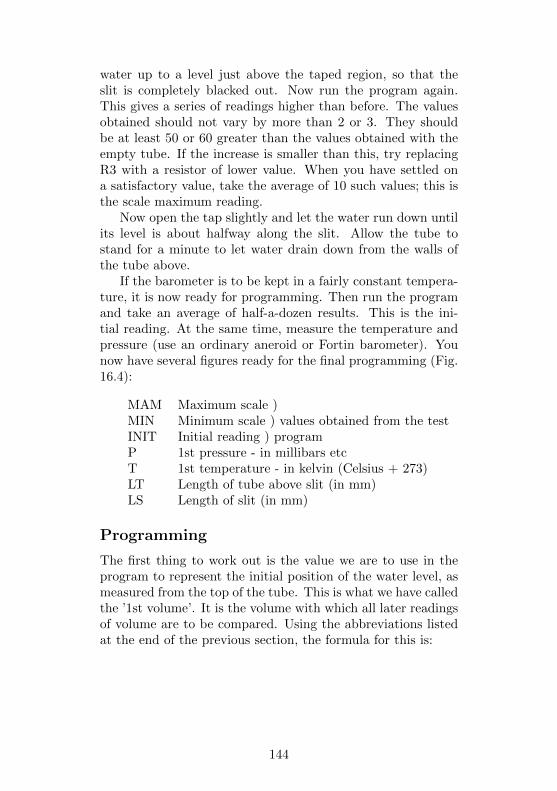
water up to a level just above the taped region, so that theslit is completely blacked out. Now run the program again.This gives a series of readings higher than before. The valuesobtained should not vary by more than 2 or 3. They shouldbe at least 50 or 60 greater than the values obtained with theempty tube. If the increase is smaller than this, try replacingR3 with a resistor of lower value. When you have settled ona satisfactory value, take the average of 10 such values; this isthe scale maximum reading.
Now open the tap slightly and let the water run down untilits level is about halfway along the slit. Allow the tube tostand for a minute to let water drain down from the walls ofthe tube above.
If the barometer is to be kept in a fairly constant tempera-ture, it is now ready for programming. Then run the programand take an average of half-a-dozen results. This is the ini-tial reading. At the same time, measure the temperature andpressure (use an ordinary aneroid or Fortin barometer). Younow have several figures ready for the final programming (Fig.16.4):
MAM Maximum scale )MIN Minimum scale ) values obtained from the testINIT Initial reading ) programP 1st pressure - in millibars etcT 1st temperature - in kelvin (Celsius + 273)LT Length of tube above slit (in mm)LS Length of slit (in mm)
Programming
The first thing to work out is the value we are to use in theprogram to represent the initial position of the water level, asmeasured from the top of the tube. This is what we have calledthe ’1st volume’. It is the volume with which all later readingsof volume are to be compared. Using the abbreviations listedat the end of the previous section, the formula for this is:
144
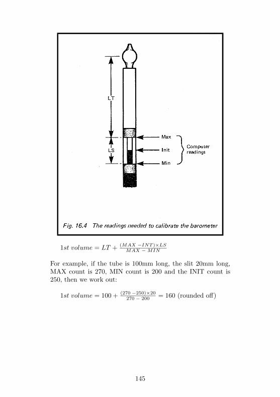
1st volume = LT + (MAX −INT )×LSMAX − MIN
For example, if the tube is 100mm long, the slit 20mm long,MAX count is 270, MIN count is 200 and the INIT count is250, then we work out:
1st volume = 100 + (270 −250)×20270 − 200 = 160 (rounded off)
145
This value is used in all later calculations until, perhaps youfind that the water ha dried out and needs replacing, in whichevent you start again with new measurements and a new valuefor 1st volume.
The same formula applies for calculating the volume atother times, except that you use the actual count obtainedin place ol INIT. For example, il the reading (x) is 230, thecomputer calculates the new volume as 111, using the line:
60 LET new = 100 + (270-x) * 20/70
We now have a new volume (the same thing as the 2nd vol-ume referred to on p. 139), which is used to work out thenew pressure. Actually, il you are not bothering to correct fortemperature there is no need to go any further. You can usethe new volume figures directly. lf pressure is rising, these fig-ures show a decrease, and conversely, if pressure is falling, thefigures rise. You then discover, by experience, just how rapidthe rise or fall has to be to predict a change in the weather.
If you want to convert the new volume into a pressure read-ing, the program line is:
70 LET pressure = 106*P/new
where P is the initial pressure. The figure 106 refers to the 1stvolume as already calculated. Your 1st volume will probablyrequire a different figure to be substituted here. The value of’pressure’ can then be displayed, and its units are the same asthose used when you read the aneroid or Fortin barometer tobegin with.
If you want to take temperature into account, you first needto program the micro to read this, using Project 15. Let us as-sume that you have done this and the temperature in degreesCelsius is held in the variable ’temp’. The unconverted pres-sure is the variable pressure calculated as already described.The line for conversion is:
80 LET pressure=pressure * T/(temp+273)
T is the initial temperature (p. 144).lf you want extra precision, you should allow for the fact
146
that the water vapour in the tube also exerts its own pres-sure, depending on temperature. An approximate correctionfor this, over the range that the barometer is likely to encountercan be added to the line above:
80 LET pressure=pressure*T/temp+273(temp+10)/27
This gives you a reading of pressure with as much exactnessas the barometer is capable. You can use it for keeping records.Check it against a proper barometer, or against a recent weathermap sometimes, as factors within the apparatus may changeand you may need to alter some of the constants of the pro-gram. Certainly the water will need topping up occasionally,and eventually need renewing, when many of the constantswill need recalculating. Thus it is better to regard this as anexperimental project, suited for detecting short-term pressurechanges and forecasting the weather accordingly.
PARTS REQUIRED for the BAROMETER
Resistors (carbon, 0.25W, 5% tolerance)R1 220kR2 100kR3 830RR4 MKY7C38E light-dependent resistor (or similar typesuch as ORP12)R5 100k
CapacitorCl 47n polyester
Integrated CircuitsIC1 CD4011 CMOS quadruple 2-input NAND gatesIC2 507C voltage-to-time converter
MiscellaneousLP1 5V 60mA filament lamp, wire ended (socket requiredif wire-ended type not used)Circuit Board8-pin IC socket14-pin IC socket3-way socket to fit 3-way plug of decoder1mm terminal pins (5 off)
147

Plastic tubing about 20cm long, about 5mm externaldiameter (e.g. aquarium aerator tubing, but must betransparent with glass-clear walls)
Tap to fit tubing (aquarium aerator line tap), or screw clipblack PVC insulating tape
Small glass or plastic jar, bottle or medicine tubeOther materials for building the assembly
148
Project 17SUNSHINE RECORDER
We finish this series of weather station projects and the book it-self in an optimistic mood! This project measures the amountof light energy arriving from the Sun over a given period oftime. It is an integrating circuit, which means that instead oftelling you HOW much energy is arriving at any given moment,it tells you how much has arrived since you last set it. Thusthe micro has only to take a reading from time to time. Thefact clouds may pass across the Sun or the shadow of a treemay pass across the garden while the micro is otherwise en-gaged, will be taken account of when the next reading is made.
How it works
This is one of the more complicated projects, but certain fea-tures of it will be familiar to you if you have already built someof the other projects. Sunlight falls on a photovoltaic cell (B1,Fig.l7.1). This is a silicon cell of the type often referred to asa solar cell. This produces a voltage of approximately 0.45Vwhen fully illuminated, the voltage depending on the amountof sunlight reaching it. This voltage is fed to an operationalamplifier (IC1) which is wired as an adder. Its function is toadd the voltage from the photocell to the voltage from thepotential-divider RVl. The reason for this will be explained ina moment.
The output of IC1 goes to a transistor Q1. This is acting asa constant-current device which is charging capacitor C1. Werely on the fact that, for any given base current, the collectorcurrent is relatively unaffected by the PD between the collectorand emitter. As Cl charges, the potential at point A rises. Theresult is that the PD between the collector and emitter of Q1decreases. However, until this PD falls much lower than weever allow it to fall, the reduction of PD does not reduce thecurrent flowing into Cl.
The amount of current flowing depends on the base current
149
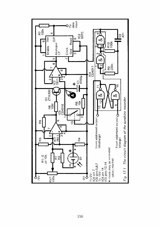
150
flowing through to Q1 from IC1 and passing through R6. Thevalue of R6 is high, to keep this current very small. Until thepotential at the output of IC1 exceeds about 0.6V there is nobase current at all and Q1 is switched off, but, in dim light thePD across B1 may be less than 0.6V. We have to ensure thatas soon as any PD is developed across B1 a Current begins toflow to Q1. This is the reason for the adder. The output of IC1is the sum of the two inputs. RV1 is set to deliver an input of0.6V, so that any additional input due to B1 goes fully towarddriving Q1.
Actually this is an inverting adder, so we apply 1.9V fromRV1 (this is 0.6V less than the half-way voltage at pin 3 ofIC1) and the cell is connected with its negative terminal toR2. This results in a positive output to Q1.
Over a period of several tens of minutes, or perhaps anhour, C1 charges at a rate depending on the amount of sunlightfrom moment to moment. The PD across C1 rises, faster whenthe Sun shines strongly, more slowly when a cloud covers it orat the end of the day, and not at all during the night. The PDIS fed to another operational amplifier, IC2, which is wired asa unity gain voltage follower. This is used as a buffer betweenC1 and the voltage-to-time converter, IC3. The input of IC3has an impedance of about 100k, which would allow currentto leak away from C1 almost as quickly as it was arrivingfrom Q1. But the input impedance of IC2, which is a CMOSIC, is extremely high (about 1 Teraohm, or 1x10¹² ohms!).Leakage to this input is virtually non-existent. The output ofIC2 follows the PD which is across C1 exactly. As explained inProject 11 (p. 102), IC3 converts this voltage into a waveform.The shape of this depends on the level of the voltage.
For IC3 to operate properly the input voltage must be inthe range 1.25V to 3.75V. During a period of measurements thePD should start at a little above 1.25V and must not exceed3.75V before the reading is taken.
The micro is given the task of adjusting the PD across C1to a little more than 1.72V each time a measurement periodis to begin. lt discharges C1 through resistor R8, which isswitched into circuit by a CMOS switch (IC5). This is con
151
trolled by a flip-flop made from two gates of IC4. The othertwo gates of this IC make up the clock for IC3 (see p. 105). Theflip-flop is controlled by two Addressed Outputs. Addressingone of these sets the flip-flop, which closes the CMOS switchand begins to discharge C1. The micro checks the PD byreading the Data Input. When the PD has reached a suitablylow level, the micro addresses the other Addressed Output.This action resets the flip-flop, which opens the CMOS switchand C1 begins to charge again. It requires a ’high’ level on pin13 of IC5 to close the switch.
The length of each measurement period is fixed so that,even with continuously brilliant sunshine, the PD across C1never exceeds 3.75V.
Building it
The project requires 5 lines to the decoder: two power lines, awire to a Data Input, and two lines from Addressed Outputs.If the solar cell (B1) is to be mounted away from the micro,the leads may be extended where marked * in Fig.17.1. Thesolar cell need not be a large one, in fact a small one is better,for it delivers less current and so allows longer measurementperiods. It is often possible to buy small fragments of solarcells very cheaply from hobby suppliers. One of these maywell prove to be suitable. This is a reminder that solar cells areeasily broken, unless you have one that is in a protective case.It must be mounted where it is protected from the weatherand physical damage yet receives full sunshine for as muchas possible of the day. The cell must be horizontal, facingupward. Fig.17.2 shows one way of protecting it. If, later, youfind that the capacitor charges too rapidly, a layer or two ofwhite paper may be fixed inside the cover to reduce the amountof light reaching the cell. Remember to clear away any debriswhich may fall on the cover, especially leaves in autumn.
Wire up IC1 and 01 and their associated components first.Do not include the connection to 105 at this stage. The cir-cuit may be tested by connecting it to a +5V or +6V supply.Connect a voltmeter across C1 (at point A). Shade B1 so that
152
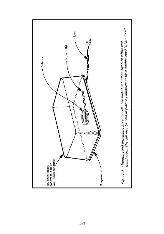
153

no light reaches it. Alter the setting of RV1 several times. Insome positions you will see the PD across C1 slowly increasing.It should take several minutes to increase by as much as 0.1V.Adjust RV1 so that the PD lust does not rise. This is thepoint at which it is delivering approximately 1.9V. You wouldneed to wait for, say, 10 minutes to make certain that no risein PD is occurring, but for the present be satisfied if it doesnot apparently change in one or two minutes. Now uncoverB1. The needles should start to move, showing a rising PD.The rate of rise depends on the amount of light. Let brightsunlight fall on it, or hold a table-lamp a few centimetres awayfrom it and the rate of rise should increase perceptibly.
Next add IC2, IC3 and IC4 to the circuit. When tested asabove, with a voltmeter connected to the output of IC2 (pin6), the same result should be obtained. With an oscilloscopeconnected to the output of IC3, you see a waveform similar tothat of Fig.11.2. The proportion of time spent in the ’high’state is gradually reduced as C1 charges.
Finally, wire up the flip-flop of IC4 and the single CMOSswitch of IC5. Note that the control inputs of the other switchesneed to be connected to either 0V or +5V (see list of connec-tions on Fig.17.1). The flip-flop may be controlled by wiringits inputs to +5V temporarily, then briefly connecting eitherone or the other to 0V instead. As the flip-flop changes statethe switch is turned off or on. When the switch is on, C1discharges.
The capacitor discharges much more rapidly than it charges,but still takes several seconds. It must not discharge toorapidly or the micro will be unable to stop the discharge atthe correct level.
Before connecting the completed device to the decoder, testall the leads to ensure that there are no short-circuits betweenthem. Plug the device into the Decoder and switch on thepower. Allow C1 to charge until the PD across it is between1.25V and 3.75V, as measured by a voltmeter.
Use a program like that on p. 106 to read the input fromthe voltage-to-time converter. Cover the photo-cell to excludeall light and set RV1 so that the reading obtained by the microdoes not decease over a long period, say 10 minutes. Of course,
154
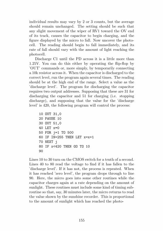
individual results may vary by 2 or 3 counts, but the averageshould remain unchanged. The setting should be such thatany slight movement of the wiper of RV1 toward the OV endof its track, causes the capacitor to begin charging, and thefigure displayed by the micro to fall. Now uncover the photo-cell. The reading should begin to fall immediately, and itsrate of fall should vary with the amount of light reaching thephotocell.
Discharge C1 until the PD across it is a little more than1.25V. You can do this either by operating the flip-flop by’OUT’ commands or, more simply, by temporarily connectinga 10k resistor across it. When the capacitor is discharged to thecorrect level, run the program again several times. The readingshould be at the high end of the range. Select a value as the’discharge level’. The program for discharging the capacitorrequires two output addresses. Supposing that these are 31 fordischarging the capacitor and 51 for charging (i.e. stoppingdischarge), and supposing that the value for the ’dischargelevel’ is 420, the following program will control the process:
10 OUT 31,0
20 PAUSE 10
30 OUT 51,0
40 LET x=0
50 FOR j=1 TO 500
60 IF IN=255 THEN LET x=x+1
70 NEXT j
80 IF x<420 THEN GO TO 10
90
Lines 10 to 30 turn on the CMOS switch for a tenth of a second.Lines 40 to 80 read the voltage to find if it has fallen to the’discharge level’. If it has not, the process is repeated. Whenit has reached ’zero level’, the program drops through to line90. Here, the micro goes into some other routines while thecapacitor charges again at a rate depending on the amount ofsunlight. These routines must include some kind of timing sub-routine so that, say, 30 minutes later, the micro returns to readthe value shown by the sunshine recorder. This is proportionalto the amount of sunlight which has reached the photo-
155
cell during the measurement period. This value may be dis-played, or stored in memory to be added to values obtainedthroughout the day.
PARTS REQUIRED for the SUNSHINE RECORDER
Resistors (carbon, 0.25W, 5% tolerance, unless otherwisespecified)
R1R5 10k, 1% tolerance (5 off)R6 10MR7, R10 100k (2 off)R8 10kR9 220kR V1 100k, miniature preset resistor
CapacitorsCl 4700 µ electrolyticC2 47n polyester
SemiconductorQ1 ZTX300 or similar npn transistor
Integrated CircuitsIC1, IC2 7611 CMOS operational amplifiers (2 off)IC3 507C voltage-to-time converter,IC4 CD4011 CMOS quadruple 2-input NAND gateIC5 CD4016 CMOS quadruple analogue switch
MiscellaneousB1 Silicon photo-voltaic cell (solar cell), small8-pin IC sockets (3 off)14-pin IC sockets (2 off)3-way sockets to fit 3-way plugs on decoder board (3 off)Circuit board1mm terminal pins (7 off)Materials for making protective case and formounting the cell
156

Appendix A:
The ADDRESS DECODER
lt is essential for you to make this, for you need it whenyou come to connect the projects to the micro. It does severalthings beside decode addresses. We will explain how it worksin some detail, but if you would rather go ahead and buildit, skip the description that follows and go straight to p.162.Fig.D.1 is the circuit diagram. All the lines coming in on theleft-hand side of the diagram come from the micro. Lines A0to A4 all go to IC1. This is a NAND logic gate. When theinputs to this gate are all ’high’ (+5V), the output of the gate(pin 8, where the small circle is), goes ’low’ (0V). The gate has8 inputs but three of these are made ’high’ permanently bywiring them to the +5V supply. Therefore the output of IC1is normally ’high’, but goes ’low’ when the address on the busis XXX1 1111. In this expression ’X’ means either 0 or 1, forit makes no difference, as lines A5 to A7 are not connected tolC1. If you look at Table 0.1, you will see that all the binarynumbers marked end with a run of five 1s, and in fact the 8numbers so marked are all the possible ones of the form XXX11111. When any one of these is on the address bus, the outputof IC1 goes ’Low’.
The output of IC1 together with the IORQ and RD lines goto another logic gate, which is one of the gates in lC2. Theseare NOR gates, and have three inputs. The output of a NORgate goes ’high’ when all its inputs are ’low’, The only condi-tions for which this can happen are:
Output of IC1 is low – address XXX1 1111 on thebus
and IORQ is ’low’ – the Z80 wants to communicatewith an external device(p. 5)
and RD is ’low’ – the Z80 wants to read datafrom that device.
This happens only when the Z80 is trying to obtain data from
157
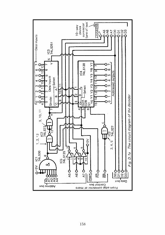
158
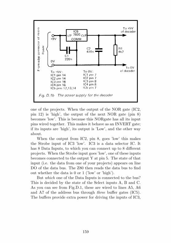
one of the projects. When the output of the NOR gate (IC2,pin 12) is ’high’, the output of the next NOR gate (pin 8)becomes ’low’. This is because this NORgate has all its inputpins wired together. This makes it behave as an INVERT gate;if its inputs are ’high’, its output is ’Low’, and the other wayabout.
When the output from IC2, pin 8, goes ’low’ this makesthe Strobe input of IC3 ’low’. IC3 is a data selector IC. Ithas 8 Data Inputs, to which you can connect up to 8 differentprojects. When the Strobe input goes ’low’, one of these inputsbecomes connected to the output Y at pin 5. The state of thatinput (i.e. the data from one of your projects) appears on lineDO of the data bus. The Z80 then reads the data bus to findout whether the data is 0 or 1 (’low’ or ’high’).
But which one of the Data Inputs is connected to the bus?This is decided by the state of the Select inputs A, B and C.As you can see from Fig.D.1, these are wired to lines A5, A6and A7 of the address bus through three buffer gates (IC5).The buffers provide extra power for driving the inputs of IC3,
159

IC4 and any other decoder circuits we may need. If thesethree lines are all ’high’, this in effect puts 111 at the Selectinputs. Binary 111 is 7 in decimal (see Table 0.1). If you havea device connected to Data Input 7 of IC3, the data from thisdevice appears at the output (Y) and goes to the data bus.When lines A5 to A7 are all 1 and lines A0 to A4 are also all1, the address on the bus is 1111 1111, or 255 in decimal. Thedevice which is connected to input 7 of IC3 has the address255. If you want the micro to read the data coming from thisdevice, you must program it to read from address 255. Theway to do this is explained later.
As another example, suppose you want to read data froma device attached to Data Input 4. Decimal 4 is 100 in binary,so A7 must be ’high’ while A6 and A5 are ’low’. The completeaddress required is 1001 1111, or 159 in decimal.
Output Y of IC3 is known as a three-state output. Whenthe Strobe input is Plow’, Y has the same level (0 or 1) asis present on the selected input line. If the input is 0, Y is0; if the input is 1, Y is 1. Y goes to its third state whenthe Strobe input goes ’high’. The third state is neither 0 nor1, but what is called ’high impedance’. It is as if the outputterminal of the IC becomes disconnected from line D0. Theability to disconnect Y is essential, for there are many otherICs connected to the data bus. The RAM and ROM ICs, thekeyboard (in some computers, but not in ZX computers), theZ80 itself and many other devices may all have connections tothe bus. If they all were putting data on to the bus at once,it would be like a room full of people all shouting together.No one would be heard. So all outputs to the bus are of thethree-state kind. When the Z80 addresses a particular IC, asit does when it makes IORQ and RD low and puts one of theiraddresses of IC3 on the address bus, only the addressed IC isable to put data on to the bus. At that time, all the other ICsare in a high-impedance state and are, in effect, disconnected.
So far, we have seen how the Z80 reads data from ourprojects. The 8 Data Inputs (Fig.D.1) are for use by thoseprojects which deliver output on only 1 line. We say they havea 1-bit output. A few projects need to transmit more than 1bit at a time. These each have their own IC with three-state
160
outputs to connect them with the data bus.Some projects do not send data to the micro, but simply
need to be told when they are to operate. All they need is abrief message to tell them when to begin. IC4 has 8 outputs,the Addressed Outputs, which are used to trigger such projectsinto action. The IC has 3 Enable inputs. G2A and G2B areconnected to the output of IC1 and to the IORQ line. Bothof these inputs must be ’low’ to enable IC4. The third Enableinput, G1, is connected to the WR line by way of an INVERTgate (part of IC2). To enable IC4, G1 must be made ’high’;this happens when WR goes low. So, if the Z80 wants to tella device to do something, it puts its address (XXX1 1111) onthe bus, and makes IORQ and WR low. This action enablesIC4.
The outputs of IC4 are normally all high, but when theIC is enabled, one of these goes low. Which one goes lowdepends on the state of the 3 Select inputs, as it did for IC3.For example, if the address is 0111 1111 (127 in decimal), thenumber is presented to the Select inputs is 011. In decimal,this is 5, so Addressed Output Y5 goes low, while the othersremain high. The device attached to output Y5 is designed soas to respond when the output goes low. In this way we cantrigger up to 8 devices to operate, simply by programming themicro to write to the appropriate Addressed Output.
A few of the projects need more than 1 data line. Thedecoder provides them with up to 4 such lines (D0 to D3), asshown at the bottom right-hand corner of Fig.D.1. These comedirectly from the data bus Of the micro. These projects arealso supplied with lines A5 to A7 (indirectly from the buffergates of IC5) as well as the decoded output of lines A0 to A4,IORQ and RD . The final stage of address decoding for theseprojects is carried out by the circuit of the project concerned.
The remaining section is a +5V regulator circuit. Thisprovides power for operating the address decoder and for allthe projects which are attached to it. The regulator drawsits supply from the +9V line of the micro. This is able tosupply only a limited amount of power (up to about 200mA,probably less if you already have a printer, disk drive or extraRAM connected).. Most of the projects in this book requireonly a few milliamps so there is no problem in powering two
161
or three of these at once. If you want to have many projectsconnected at one time, it is advisable to use a separate unreg-ulated DC power pack. You could employ a second ZX Powerpack, or any other pack which delivers rectified direct currentof suitable voltage. The regulator IC can be powered by anysupply voltage in the range 7V to 25V, and delivers a currentof up to 1A. If you use a separate power pack rather than thesupply from the micro, the circuit diagram and PCB layoutmust be modified.
Building the project
If you want to be able to run a printer, extra RAM or diskdrives at the same time as the projects, adopt the method ofconnection shown in Fig. D.2. Fig. D.3 shows the expan-sion board with keyway positioning. If you are connecting theproject to a Spectrum,which has a 28-way connection, withthe key at position 5, you can use an edge connector socket ofthis description, though there is no need to do so. As Fig. 0.1shows, the projects do not use any of the lines at the ends ofthe Spectrum connector and a socket which fits the ZX81 canbe plugged on to the Spectrum too. On the Ace, the key isat position 23, so we simply turn the connector the other wayup. The lugs of the socket pass through a row of holes in thecircuit and are soldered to the board. The lugs are then bentslightly to bring the two rows closer together and are solderedto a strip of board which acts as an edge connector for anyother device (such as the printer) which you may want to plugon to the system. This is a double-sided board with 22 paralleltracks (27 for the Spectrum) on each surface (Fig. D.3). If youhave a ZX81 and think it likely that you will be upgrading toa Spectrum, it is worthwhile to provide a board with 27 tracksper surface at this stage.
Fig.D.4 shows the design of a PCB for the project. Thisis reproduced full size, so you can trace it or photocopy it ifyou want to make the board yourself. The board is also onsale ready-made from the supplier named on p. 179. If youdecide to design your own PCB or to assemble the project onstripboard, note the way in which connections are
162
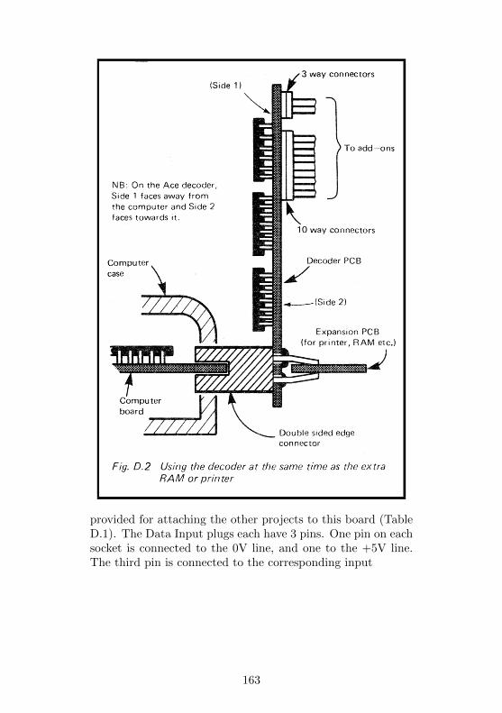
provided for attaching the other projects to this board (TableD.1). The Data Input plugs each have 3 pins. One pin on eachsocket is connected to the 0V line, and one to the +5V line.The third pin is connected to the corresponding input
163
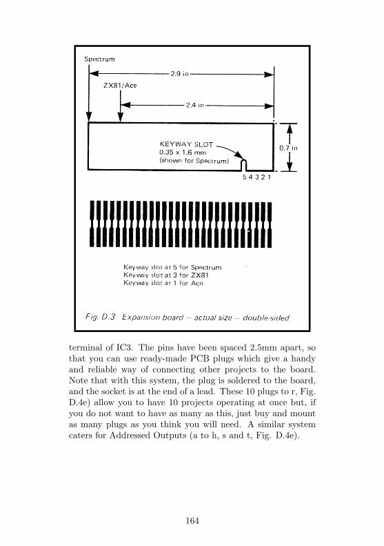
terminal of IC3. The pins have been spaced 2.5mm apart, sothat you can use ready-made PCB plugs which give a handyand reliable way of connecting other projects to the board.Note that with this system, the plug is soldered to the board,and the socket is at the end of a lead. These 10 plugs to r, Fig.D.4e) allow you to have 10 projects operating at once but, ifyou do not want to have as many as this, just buy and mountas many plugs as you think you will need. A similar systemcaters for Addressed Outputs (a to h, s and t, Fig. D.4e).
164
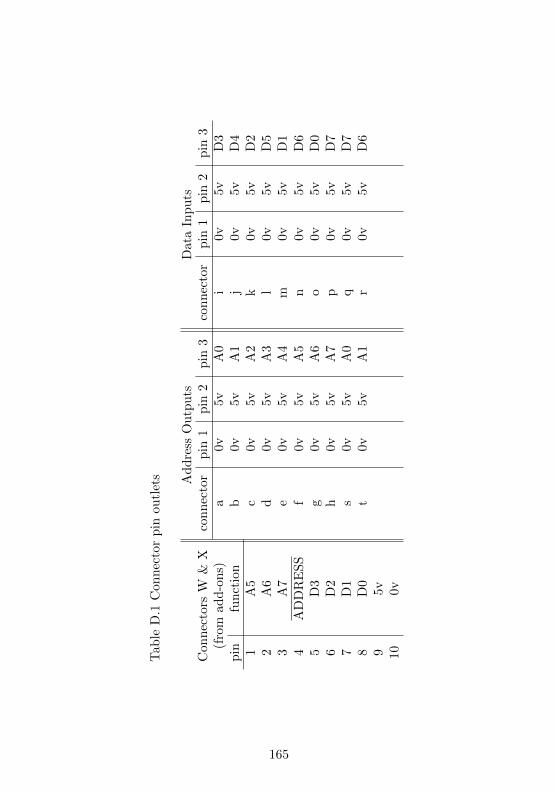
Tab
leD
.1C
on
nec
tor
pin
ou
tlet
s Ad
dre
ssO
utp
uts
Data
Inp
uts
Con
nec
tors
W&
Xco
nn
ecto
rp
in1
pin
2pin
3co
nn
ecto
rp
in1
pin
2p
in3
(fro
mad
d-o
ns)
a0v
5v
A0
i0v
5v
D3
pin
fun
ctio
nb
0v
5v
A1
j0v
5v
D4
1A
5c
0v5v
A2
k0v
5v
D2
2A
6d
0v5v
A3
l0v
5v
D5
3A
7e
0v5v
A4
m0v
5v
D1
4A
DD
RE
SS
f0v
5vA
5n
0v
5v
D6
5D
3g
0v5v
A6
o0v
5v
D0
6D
2h
0v5v
A7
p0v
5v
D7
7D
1s
0v
5v
A0
q0v
5v
D7
8D
0t
0v5v
A1
r0v
5v
D6
95v
100v
165
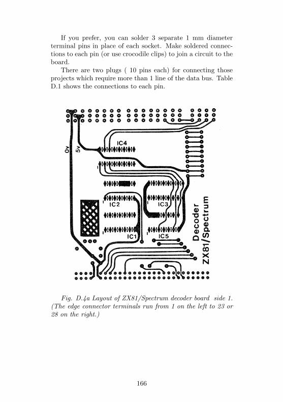
If you prefer, you can solder 3 separate 1 mm diameterterminal pins in place of each socket. Make soldered connec-tions to each pin (or use crocodile clips) to join a circuit to theboard.
There are two plugs ( 10 pins each) for connecting thoseprojects which require more than 1 line of the data bus. TableD.1 shows the connections to each pin.
Fig. D.4a Layout of ZX81/Spectrum decoder board side 1.(The edge connector terminals run from 1 on the left to 23 or28 on the right.)
166
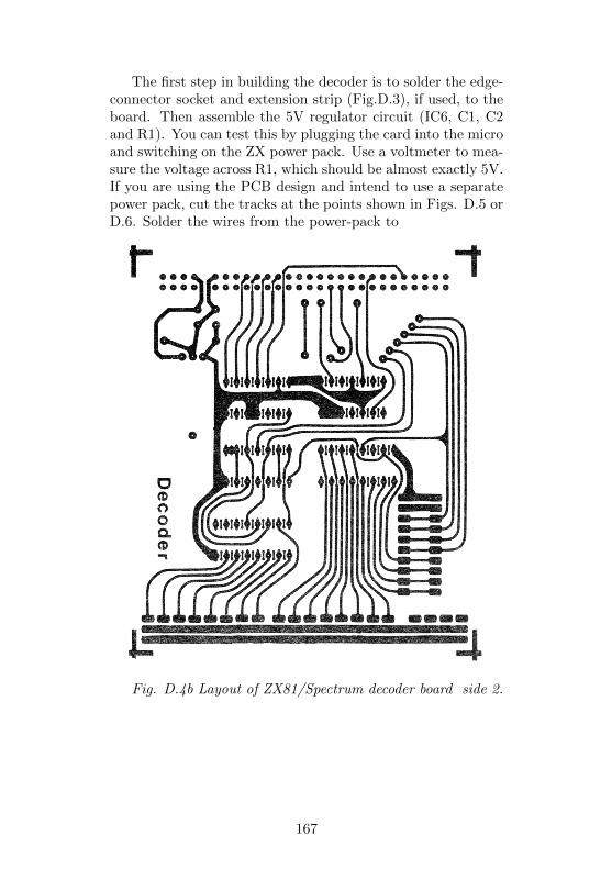
The first step in building the decoder is to solder the edge-connector socket and extension strip (Fig.D.3), if used, to theboard. Then assemble the 5V regulator circuit (IC6, C1, C2and R1). You can test this by plugging the card into the microand switching on the ZX power pack. Use a voltmeter to mea-sure the voltage across R1, which should be almost exactly 5V.If you are using the PCB design and intend to use a separatepower pack, cut the tracks at the points shown in Figs. D.5 orD.6. Solder the wires from the power-pack to
Fig. D.4b Layout of ZX81/Spectrum decoder board side 2.
167
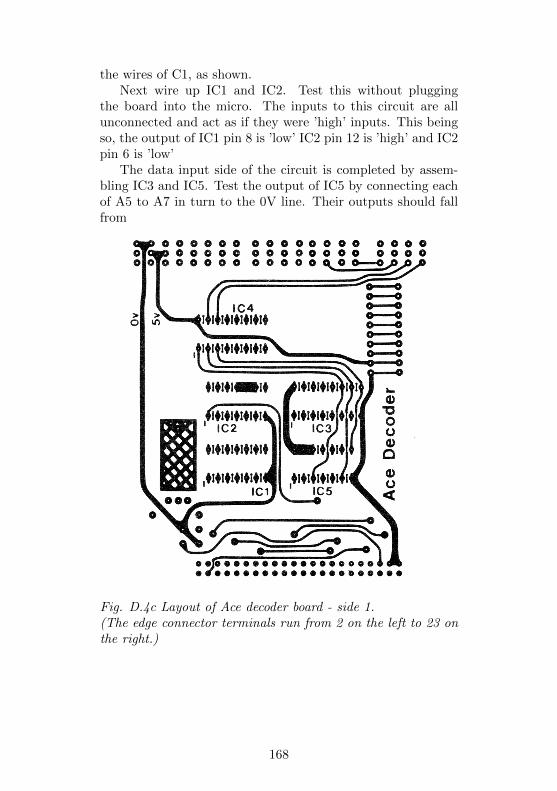
the wires of C1, as shown.Next wire up IC1 and IC2. Test this without plugging
the board into the micro. The inputs to this circuit are allunconnected and act as if they were ’high’ inputs. This beingso, the output of IC1 pin 8 is ’low’ IC2 pin 12 is ’high’ and IC2pin 6 is ’low’
The data input side of the circuit is completed by assem-bling IC3 and IC5. Test the output of IC5 by connecting eachof A5 to A7 in turn to the 0V line. Their outputs should fallfrom
Fig. D.4c Layout of Ace decoder board - side 1.(The edge connector terminals run from 2 on the left to 23 onthe right.)
168
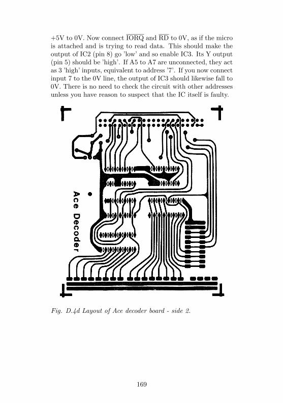
+5V to 0V. Now connect IORQ and RD to 0V, as if the microis attached and is trying to read data. This should make theoutput of IC2 (pin 8) go ’low’ and so enable IC3. Its Y output(pin 5) should be ’high’. If A5 to A7 are unconnected, they actas 3 ’high’ inputs, equivalent to address ’7’. If you now connectinput 7 to the 0V line, the output of IC3 should likewise fall to0V. There is no need to check the circuit with other addressesunless you have reason to suspect that the IC itself is faulty.
Fig. D.4d Layout of Ace decoder board - side 2.
169
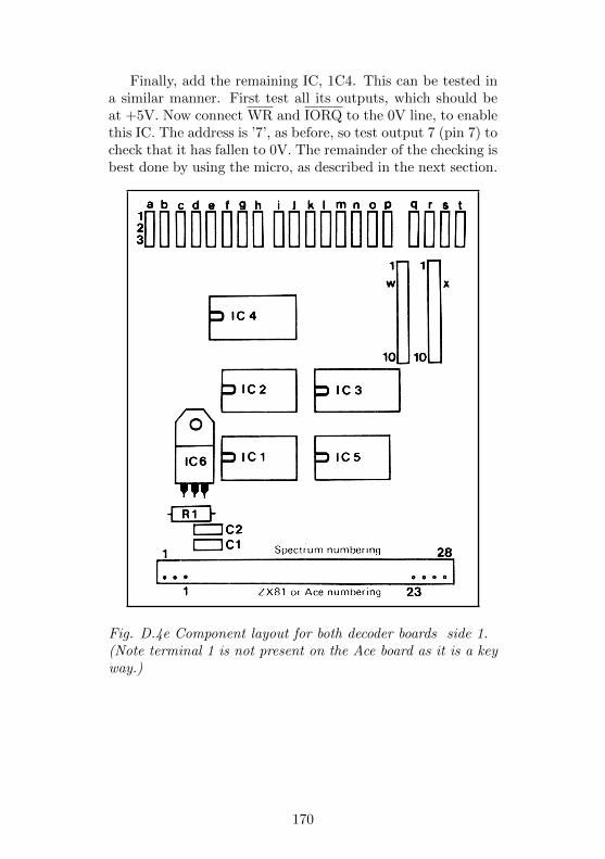
Finally, add the remaining IC, 1C4. This can be tested ina similar manner. First test all its outputs, which should beat +5V. Now connect WR and IORQ to the 0V line, to enablethis IC. The address is ’7’, as before, so test output 7 (pin 7) tocheck that it has fallen to 0V. The remainder of the checking isbest done by using the micro, as described in the next section.
Fig. D.4e Component layout for both decoder boards side 1.(Note terminal 1 is not present on the Ace board as it is a keyway.)
170
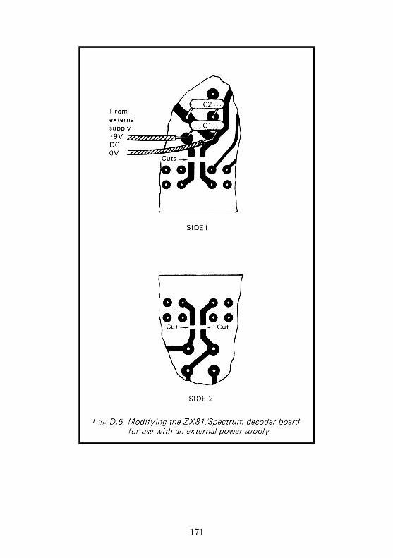
171
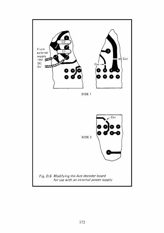
172
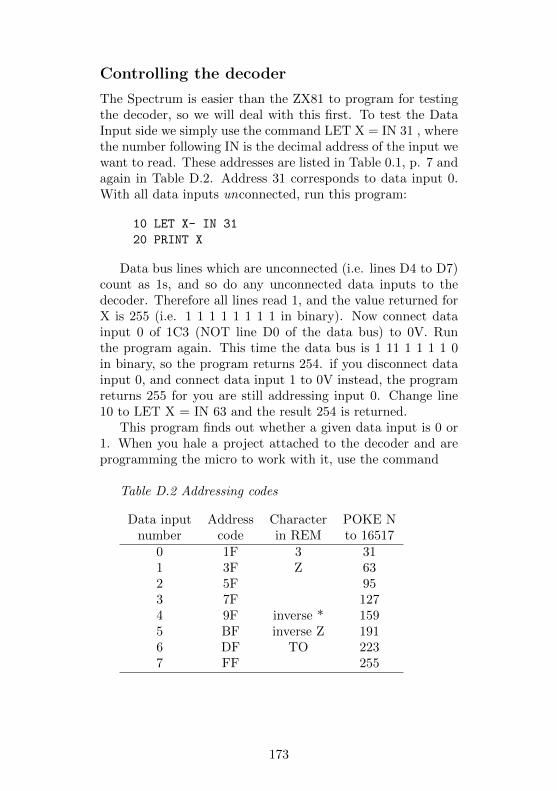
Controlling the decoder
The Spectrum is easier than the ZX81 to program for testingthe decoder, so we will deal with this first. To test the DataInput side we simply use the command LET X = IN 31 , wherethe number following IN is the decimal address of the input wewant to read. These addresses are listed in Table 0.1, p. 7 andagain in Table D.2. Address 31 corresponds to data input 0.With all data inputs unconnected, run this program:
10 LET X- IN 31
20 PRINT X
Data bus lines which are unconnected (i.e. lines D4 to D7)count as 1s, and so do any unconnected data inputs to thedecoder. Therefore all lines read 1, and the value returned forX is 255 (i.e. 1 1 1 1 1 1 1 1 in binary). Now connect datainput 0 of 1C3 (NOT line D0 of the data bus) to 0V. Runthe program again. This time the data bus is 1 11 1 1 1 1 0in binary, so the program returns 254. if you disconnect datainput 0, and connect data input 1 to 0V instead, the programreturns 255 for you are still addressing input 0. Change line10 to LET X = IN 63 and the result 254 is returned.
This program finds out whether a given data input is 0 or1. When you hale a project attached to the decoder and areprogramming the micro to work with it, use the command
Table D.2 Addressing codes
Data input Address Character POKE Nnumber code in REM to 16517
0 1F 3 311 3F Z 632 5F 953 7F 1274 9F inverse * 1595 BF inverse Z 1916 DF TO 2237 FF 255
173
”IF . . . .TH EN. . .” to make the micro perform one actionif X = 254, and a different action if X = 255.
The Addressed Output section is tested in a similar way,but there is one small problem. The IORQ and WR lines arein their active-low state for such a short time that you can notuse a voltmeter to detect the brief fall in voltage at the out-put of IC4. Even an oscilloscope will not show what happens.The best method is to build a simple pulse detector. Project 1describes how to do this. Connect the detector to output YO(pin 15), reset the detector (LED on) and run this program:
10 OUT 15,0
The 15 is the address of YO. The 0 is the data which is sup-posed to go to this address, but in this case we are not sendingany data. ft is sufficient to address the output. When you runthe program, the LED goes out. The other outputs can betested in the same way, but using their addresses (Table D.2)instead.
Programming the ZX81
The Z80 microprocessor inside the ZX81 can do just the samethings as the Z80 inside the Spectrum, but the ZX81 does nothave the IN and OUT commands in its BASIC. We have touse a machine-code program to tell the ZX81 to communicatewith attached devices. Fortunately, these programs are veryshort. The program for reading from a data input (equivalentto using IN, as described above for the Spectrum) is simplythis:
06 FF LDB, FF0E 1F LDC, 1F (the address)ED 48 IN C,C (read address port)C9 RET
Do not worry if you do not understand what machine codeis all about. It is listed here just as a matter of interest forthose who do. You can use the program from an ordinaryBASIC program without the need to know how it works. Thebest way of using this program is to place it at the very
174
beginning of your BASIC program, in the form of a REM state-ment. Chapter 26 of the ZX81 Handbook explains somethingabout this.
Here is a BASIC program which puts the machine codeprogram in memory from address 16514 (where all BASICprograms begin), and lets you use it by means of the USRcommand:
10 REM [] :3 TAN
20 POKE 16515, 255
30 POKE 16518, 237
40 POKE 16519, 72
50 LET X = USR 16514
60 PRINT X
70 STOP
The REM puts some of the machine code groups directly intomemory by making the ZX81 store the codes which correspondto various symbols and characters (see Appendix A of the ZX81Handbook). The 3, for example, gives the code for 1F, theaddress of Data Input 0 of the address decoder. Type in line10 with great care, leaving one or two spaces where shown.
Some codes can not be put in as a REM statement so wePOKE them in with lines 20 to 40. Line 50 makes the mi-cro run the machine code routine from address 16514 onward.When it comes back again, having read the input from datainput 0, the value of X tells us what is in the B and C reg-isters of the Z80. We already know that register B contains1111 1111 for we put it there with the program. Register Cshows the data which has just been read. This is 1111 1111 ifall, lines are high (all data inputs left unconnected), and 11111110 if data input 0 has been connected to the 0V line. So Xhas one of two values:
1111 1111 1111 1111, which is 65535 (=high input)or 1111 1111 1111 1110, which is 65534 (=low output)
When you run this program the number 65535 or 65534 ap-pears at the top left corner of the screen.
When the program has been run once, the ’missing’ codeswill have been inserted in the REM line, so do not be surprised
175
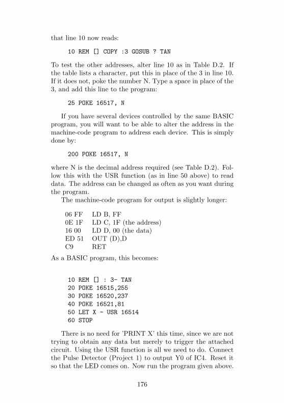
that line 10 now reads:
10 REM [] COPY :3 GOSUB ? TAN
To test the other addresses, alter line 10 as in Table D.2. Ifthe table lists a character, put this in place of the 3 in line 10.If it does not, poke the number N. Type a space in place of the3, and add this line to the program:
25 POKE 16517, N
If you have several devices controlled by the same BASICprogram, you will want to be able to alter the address in themachine-code program to address each device. This is simplydone by:
200 POKE 16517, N
where N is the decimal address required (see Table D.2). Fol-low this with the USR function (as in line 50 above) to readdata. The address can be changed as often as you want duringthe program.
The machine-code program for output is slightly longer:
06 FF LD B, FF0E 1F LD C, 1F (the address)16 00 LD D, 00 (the data)ED 51 OUT (D),DC9 RET
As a BASIC program, this becomes:
10 REM [] : 3- TAN
20 POKE 16515,255
30 POKE 16520,237
40 POKE 16521,81
50 LET X - USR 16514
60 STOP
There is no need for ’PRINT X’ this time, since we are nottrying to obtain any data but merely to trigger the attachedcircuit. Using the USR function is all we need to do. Connectthe Pulse Detector (Project 1) to output Y0 of IC4. Reset itso that the LED comes on. Now run the program given above.
176

The LED goes out immediately. You can test other outputs byusing other addresses. Table D.2 tells you what to use insteadof the 3.
As with the other program, new symbols appear in theREM after the program has been run once:
10 REM [] COPY :3 GOSUB ? TAN
There are two spaces after the . The first of these correspondsto the data (a space is code 00). With Project 4 you need tosend data to the data latches. In this case you will need tomodify the program by substituting one of the symbols shownin Table 4.1 for the first space after the . As with the firstprogram, you can POKE different addresses into the machine-code program at any stage during your BASIC program so asto control several devices at once.
With this program and the other you can delete the ’POKE’lines when the program has been run once, for the first runplaces all the required codes in memory. These programs maybe saved on tape or disk. After the first time the programis run, the REM line holds the address of the first device tobe addressed by that program. If your BASIC program iscontrolling several devices with different addresses, note thatthe saved version holds the address of the last device to beused. If this is not the same as the first device, your programmust begin by POKEing in the address of the first device.
If you want to read and write in the same program, bothmachine code programs may be placed one after the other. Thecombined program is:
10 REM []:3 TAN[]:3 TAN
20 POKE 16515,255
30 POKE 16518,237
40 POKE 16519,72
50 POKE 16522,255
60 POKE 16527,237
70 POKE 16528,81
Run the program once, then delete lines 20 to 70. These canbe replaced by lines of your own program. To read data, usethe statement LET X = USR 16514 as before. To write data
177
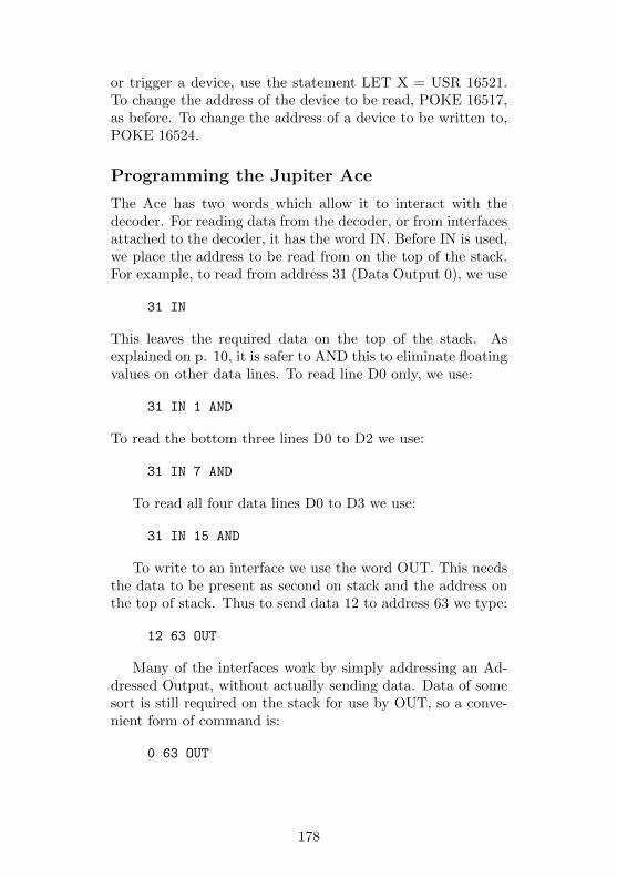
or trigger a device, use the statement LET X = USR 16521.To change the address of the device to be read, POKE 16517,as before. To change the address of a device to be written to,POKE 16524.
Programming the Jupiter Ace
The Ace has two words which allow it to interact with thedecoder. For reading data from the decoder, or from interfacesattached to the decoder, it has the word IN. Before IN is used,we place the address to be read from on the top of the stack.For example, to read from address 31 (Data Output 0), we use
31 IN
This leaves the required data on the top of the stack. Asexplained on p. 10, it is safer to AND this to eliminate floatingvalues on other data lines. To read line D0 only, we use:
31 IN 1 AND
To read the bottom three lines D0 to D2 we use:
31 IN 7 AND
To read all four data lines D0 to D3 we use:
31 IN 15 AND
To write to an interface we use the word OUT. This needsthe data to be present as second on stack and the address onthe top of stack. Thus to send data 12 to address 63 we type:
12 63 OUT
Many of the interfaces work by simply addressing an Ad-dressed Output, without actually sending data. Data of somesort is still required on the stack for use by OUT, so a conve-nient form of command is:
0 63 OUT
178

PARTS REQUIRED for the ADDRESS DECODER *Items marked * are optional
ResistorR1 4k7, 0.25W, 5% tolerance
CapacitorsC1 220n polyesterC2 470n polyester
Integrated CircuitsIC1 74LS30 8-input NAND gateIC2 74LS27 triple 3-input NOR gateIC3 74LS251 8-line to 1-line data selector/multiplexerIC4 74LS138 3-to-8 line decoder/multiplexerIC5 74LS125 quadruple bus buffer gate with three-stateoutputIC6 7805 voltage regulator, 5V, 1A
MiscellaneousStripboard or ready-made PCB*Extender boardEdge-connector to suit machine (pin 1-28 marked forSpectrum; pin 1-23 marked for ZX81 and Ace)*14-pin IC sockets (3 off)*16 pin IC sockets (2 off)*3-way connector and socket (at) (20 off)*10-way connector and socket (w & x) (2 off)*1mm Terminal pins (if used instead of PCB plugs)
* The double-sided plated through hole printed circuit board forthe Decoder, together with all necessary components either in kitform or as individual items are available from:
KELAN (HOBBYBOARD),A DIVISION OF KELAN ENGINEERING LTD,HOOKSTONE PARK, HARROGATE,NORTH YORKSHIRE, HG2 7BU, ENGLAND.Telephone: Harrogate 10423) 883672
PLEASE NOTE: The Publishers are in no way responsible for the
manufacture or supply of the above and all enquiries must be sent
directly to Kelan (Hobbyboard).
179
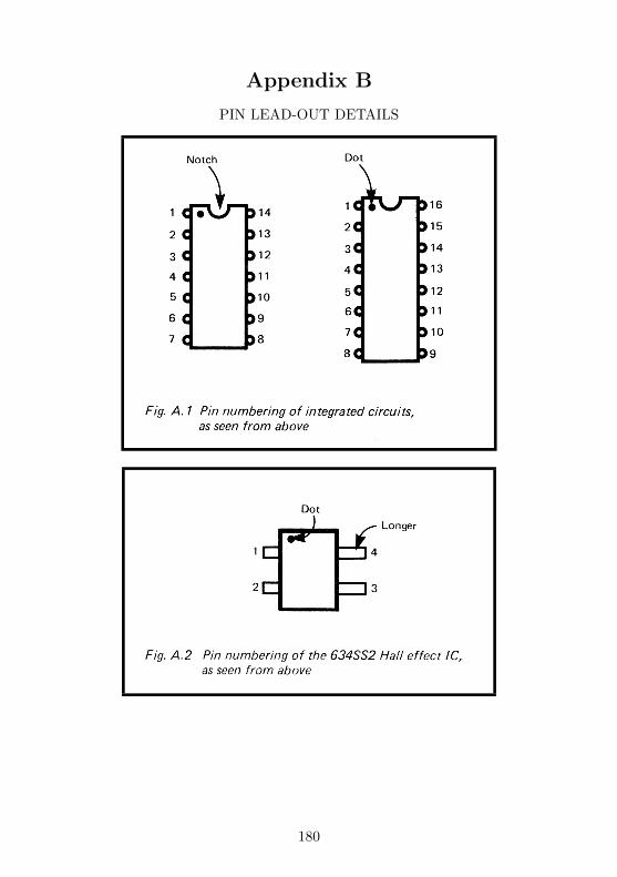
Appendix B
PIN LEAD-OUT DETAILS
180
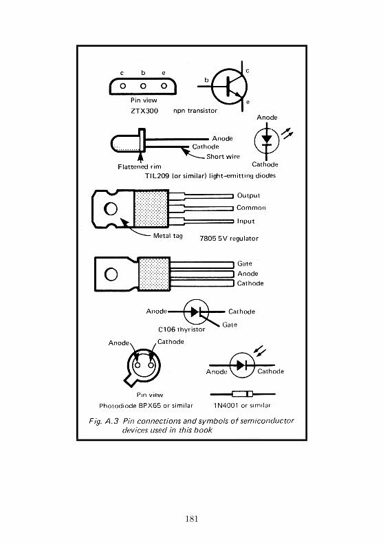
181

SPECIAL NOTE FOR READERS IN USA
The ZX81 is available in the USA under that name or as theTimex-Sinclair TS 1000. When this book was in preparationboth the ZX Spectrum and Jupiter Ace were imminently duefor launching in America.
The circuits in this book have not been tested with the ver-sions of these machines marketed in the USA, but providingthe USA versions have not been radically changed in those de-tails which relate to the operation of the add-ons, it is thoughtthat the reader should not experience any difficulties in thisdirection.
Almost all the integrated circuits specified in the projectsoriginate from the USA, so there should be no difficulties inobtaining these. Below are brief details of components whichmay not be so readily available:
BPX65 photodiode: planar 1 mm sq. silicon PIN photodiode, in T018 case with glass window. Almost any photo-diode can be substituted for this.
C106 p-gate thyristor: since this is operated at low voltage,almost any other type will do.
MKY7C38E: any light dependent resistor, with darkresistance about 300 k and sunlight resistance 100 ohms.One with small diameter is preferred.
ZTX300 transistor: any npn transistor with gain of 100 ormore and able to take a 500 mA collector current.
311 is the LF311 comparator IC.
7611 is the lCL7611 CMOS operational amplifier.
182

Please note overleaf is a list of other titles that are available inour range of Radio, Electronics and Computer Books. Theseshould be available from all good Booksellers, Radio Compo-nent Dealers and Mail Order Companies.
However, should you experience difficulty in obtaining anytitle in your area, then please write directly to the publisherenclosing payment to cover the cost of the book plus adequatepostage.
If you would like a complete catalogue of our entire rangeof Radio, Electronics and Computer Books then please send aStamped Addressed Envelope to:
BERNARD BABANI (publishing) LTDTHE GRAMPIANS
SHEPHERDS BUSH ROADLONDON W6 7NF
ENGLAND
183


![Pimpin' [Software Projects] Ain't Easy](https://img.pdfslide.net/doc/110x75/555e236cd8b42a6a4c8b4d39/pimpin-software-projects-aint-easy.jpg)