Embed Size (px)
Citation preview

SM
11
0 E
N R
EV
02
20
18
_05
EASY BASIC
INSTALLATION, USE AND MAINTENANCE MANUAL
To be kept by the purchaser
Wood operated air system stove
EASY 60 BASIC - EASY 68 BASIC (9 kW and 11 kW) - EASY 80 BASIC

Dear Customer, thank you for having chosen to heat and save with a Jolly Mec product. Please carefully read and keep this sheet
before using the equipment. This sheet provides necessary information and suggestions on how to correctly install, use, clean and maintain
the product. Knowing and observing these instructions will allow you to fully and safely enjoy the potential your equipment can offer you.

SM110 EN REV02 2018_05 3
EN
GL
ISH
TABLE OF CONTENTS
CHAP.01 PREMISES...................................................................................................................................4 01.1 WARNINGS .................................................................................................................................................. 4 01.2 SYMBOLOGY ............................................................................................................................................... 5 01.3 APPLIED STANDARDS ............................................................................................................................... 5 01.4 USE AND STORING OF THE INSTALLATION AND MAINTENANCE MANUAL ........................................ 6 01.5 MANUFACTURER’S LIABILITY AND WARRANTY CONDITIONS ............................................................. 6
CHAP.02 ACCIDENT PREVENTION / SAFETY REGULATIONS ..............................................................7 02.1 GENERAL CONSIDERATIONS ................................................................................................................... 7 02.2 SAFETY REGULATIONS FOR ROUTINE MAINTENANCE AND USE ....................................................... 7 02.3 SAFETY REGULATIONS FOR EXTRAORDINARY MAINTENANCE AND INSTALLATION ...................... 8 02.4 EQUIPMENT FOR OPERATORS AND MAINTENANCE PERSONNEL ..................................................... 9 02.5 RESIDUAL RISKS ........................................................................................................................................ 9
CHAP.03 HANDLING AND TRANSPORT ................................................................................................10 03.1 RECEIVING GOODS .................................................................................................................................. 10 03.2 LIFTING AND TRANSPORT ...................................................................................................................... 10
CHAP.04 ECOLOGICAL REGULATIONS ................................................................................................11 04.1 DISPOSAL OF THE MACHINE .................................................................................................................. 11
CHAP.05 DESCRIPTION...........................................................................................................................12 05.1 PRODUCT PRESENTATION ..................................................................................................................... 12 05.2 PRODUCT IDENTIFICATION .................................................................................................................... 13
CHAP.06 TECHNICAL DATA ...................................................................................................................14 06.1 HOMOLOGATION ...................................................................................................................................... 14 06.2 RECOMMENDED FUELS .......................................................................................................................... 15 06.3 COMPONENTS .......................................................................................................................................... 16 06.4 DIMENSIONS ............................................................................................................................................. 17
CHAP.07 POSITIONING AND CONNECTIONS FOR THE INSTALLER .................................................18 07.1 FLUE OR FUME EXHAUST SYSTEM ....................................................................................................... 18 07.2 INSTALLATION ROOM VENTILATION ..................................................................................................... 19 07.3 ASSEMBLY SEQUENCE ........................................................................................................................... 20 07.4 SAFETY DISTANCES FROM SURROUNDING FLAMMABLE MATERIALS ............................................ 24
CHAP.08 USE AND MAINTENANCE FOR THE USER ............................................................................25 08.1 CONTROL UNIT ......................................................................................................................................... 25 08.2 APPLIANCE START AND USE .................................................................................................................. 25 08.3 TIPS FOR THE USER ................................................................................................................................ 27 08.4 ROUTINE MAINTENANCE ........................................................................................................................ 28 08.5 EXTRAORDINARY MAINTENANCE .......................................................................................................... 29
CHAP.09 FAULT DIAGNOSIS AND TROUBLESHOOTING ....................................................................30 09.1 PROBLEMS ................................................................................................................................................ 30

4
CHAP.01 PREMISES
01.1 WARNINGS
• Familiarityandcompliancewiththeinstructionsgiveninthismanualwillensurequickinstallationandcorrectuseoftheappliance.
• Readthemanualattentivelybeforecommencinginstallation,andbecertaintofollowthedirectionsitcontains,otherwisethewar-rantycouldbeinvalidatedandtheperformanceandsafetyoftheappliancejeopardized.
• Theinstallationmanualisanintegralpartoftheproductandmustbegiventotheuser.
• Itmustbekeptinasafeplaceandconsultedcarefully,asallofthewarningsprovideimportantinformationonsafetyduringinstal-lation,useandmaintenance.
• Incorrectinstallationoftheappliancecouldcausedamageandinjurytopeopleoranimals,forwhichthemanufacturecannotnotbeheldliable.
• InstallationshallbeperformedbyqualifiedoperatorsinaccordancewiththeregulationsinforceintheCountryofinstallation.
• Themanufacturerdeclinesanycontractualornon-contractualliabilityfordamagescausedbyerrorsininstallationoruseoftheapplianceorfailuretofollowtheinstructionscontainedinthismanual.
• AllrightsonthereproductionofthistechnicalmanualareownedbyJollyMecCaminettiS.p.A.
• Thedescriptionsandillustrationsprovidedinthefollowingpublicationarenotbinding.
• JollyMecCaminettiS.p.Areservestherighttomakeanymodificationsthatmaybedeemedappropriate.
• ThismanualcannotbegiventothirdpartiesforperusalwithoutthewrittenpermissionofJollyMecCaminettiS.p.A
• Thetechnicaldirectionsforinstallationcontainedinthismanualshouldbeconsideredasbasicrequirements.Regulationsinsomecountriesmaybemorerestrictive;inthisinstance,complyfullywiththeregulationsprevailinginthecountryofinstallation(all laws and local bylaws must be observed when installing and using the appliance, including those referring to national and European standards).
• Neverusetheapplianceasanincinerator,orinwayotherthanthatforwhichitwasdesigned.Anyotheruseisdeemedimproperandthereforedangerous.
• Donotusefuelsthatarenotrecommendedunderpenaltyofcancellationofthewarranty.
• Whentheapplianceisrunning,theglassandothervisiblepartsreachextremelyhottemperaturestothetouch;handlewithextremecaretoavoidburns.
• Donotplacetheapplianceindirectcontactwithcombustiblematerials.
• Donotmakeanyunauthorisedmodificationtotheappliance.Anyunauthorisedmodificationwillautomaticallyinvalidatethewarrantyandreleasethemanufacturefromallliability.
• Useonlyoriginalsparepartsrecommendedbythemanufacturer.Originalsparepartsareavailablethroughretailers,specialisedTechnicalServiceCenters,ordirectlyattheheadofficeofJollyMecCaminettiS.p.A.
• Acceptanceofthemachinebytheusermustbe“total”,includingthesoundlevelofoperation,comparabletoanelectricalappliance.Complaintsforcharacteristicsnotindicatedinthismanualshallnotbeaccepted.
EN
GL
ISH
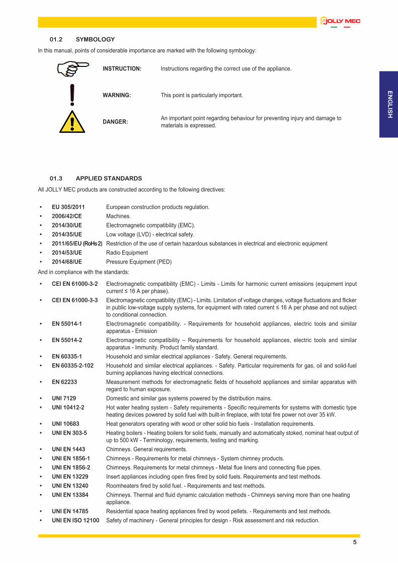
01.2 SYMBOLOGY
In this manual, points of considerable importance are marked with the following symbology:
INSTRUCTION: Instructions regarding the correct use of the appliance.
WARNING: This point is particularly important.
DANGER: An important point regarding behaviour for preventing injury and damage to materials is expressed.
01.3 APPLIED STANDARDS
All JOLLY MEC products are constructed according to the following directives:
• EU 305/2011 European construction products regulation.• 2006/42/CE Machines.• 2014/30/UE Electromagnetic compatibility (EMC).• 2014/35/UE Low voltage (LVD) - electrical safety.• 2011/65/EU (RoHs 2) Restriction of the use of certain hazardous substances in electrical and electronic equipment• 2014/53/UE Radio Equipment• 2014/68/UE Pressure Equipment (PED)
And in compliance with the standards:
• CEI EN 61000-3-2 Electromagnetic compatibility (EMC) - Limits - Limits for harmonic current emissions (equipment input current ≤ 16 A per phase).
• CEI EN 61000-3-3 Electromagnetic compatibility (EMC) - Limits. Limitation of voltage changes, voltage fluctuations and flicker in public low-voltage supply systems, for equipment with rated current ≤ 16 A per phase and not subject to conditional connection.
• EN 55014-1 Electromagnetic compatibility. - Requirements for household appliances, electric tools and similar apparatus - Emission
• EN 55014-2 Electromagnetic compatibility – Requirements for household appliances, electric tools and similar apparatus - Immunity. Product family standard.
• EN 60335-1 Household and similar electrical appliances - Safety. General requirements.• EN 60335-2-102 Household and similar electrical appliances. - Safety. Particular requirements for gas, oil and solid-fuel
burning appliances having electrical connections.• EN 62233 Measurement methods for electromagnetic fields of household appliances and similar apparatus with
regard to human exposure.• UNI 7129 Domestic and similar gas systems powered by the distribution mains.• UNI 10412-2 Hot water heating system - Safety requirements - Specific requirements for systems with domestic type
heating devices powered by solid fuel with built-in fireplace, with total fire power not over 35 kW.• UNI 10683 Heat generators operating with wood or other solid bio fuels - Installation requirements.• UNI EN 303-5 Heating boilers - Heating boilers for solid fuels, manually and automatically stoked, nominal heat output of
up to 500 kW - Terminology, requirements, testing and marking.• UNI EN 1443 Chimneys. General requirements.• UNI EN 1856-1 Chimneys - Requirements for metal chimneys - System chimney products.• UNI EN 1856-2 Chimneys. Requirements for metal chimneys - Metal flue liners and connecting flue pipes.• UNI EN 13229 Insert appliances including open fires fired by solid fuels. Requirements and test methods.• UNI EN 13240 Roomheaters fired by solid fuel. - Requirements and test methods.• UNI EN 13384 Chimneys. Thermal and fluid dynamic calculation methods - Chimneys serving more than one heating
appliance.• UNI EN 14785 Residential space heating appliances fired by wood pellets. - Requirements and test methods.• UNI EN ISO 12100 Safety of machinery - General principles for design - Risk assessment and risk reduction.
5

6
In the event of a malfunction or intervention request by a specialised Technical Service Center, the user must be able to demonstrate the use of fuel with the characteristics required by this manual.The Manufacturer disclaims all liability concerning anomalies or malfunctions caused by use of FUEL which does not comply with the recommended requirements.
NOTE
01.4 USE AND STORING OF THE INSTALLATION AND MAINTENANCE MANUAL
• Recipients of the manual
The use and installation manual is addressed to users responsible for the installation, operation and maintenance of the stove; particular attention must be given the parts of the manual concerning safety.If the product is subsequently resold, the user is requested to hand over this sheet and to inform the manufacturer of the name of the new owner, so that the latter may receive any updates issued.• Scope of the manual
The manual contains information on the correct use of the product in accordance with the purposes for which it was designed and built. It also provides information about loads, commissioning, repair and maintenance of the stove in conformance with the limits set down by the manufacturer.• Conservation of the manual
The installation and maintenance manual is an integral part of the product and must be conserved up to the time when the stove is dismantled. It must be kept in a protected, dry place out of direct sunlight and near the product so that it is always readily available for consultation.Should the manual get damaged, the user must request a copy from the retailer where he purchased the appliance. When requesting assistance, always make reference to the MODEL, LOT and SERIAL NUMBER indicated on the label shown in CHAP.05.2 - PRODUCT IDENTIFICATION.
• Updating the manual
The installation and maintenance manual reflects the status of the technology at the time the product was marketed. The manufacturer reserves the right to make modifications to the product, and consequently the relative manual, without any obligation to update previous editions.
01.5 MANUFACTURER’S LIABILITY AND WARRANTY CONDITIONS
Upon the delivery of this manual, Jolly Mec S.p.A. cannot be held liable, whether civil or criminal, for accidents due to partial or total non-compliance with the specifications herein contained.The manufacturer is especially held harmless from any liability in the following cases:• Improper use of the product• Use not intended by specific national regulations• Incorrect installation• Faults in the electrical connections, the connections of the fume exhaust system and/or the comburent air ducting system e and in
plumbing connections• Failure to carry out maintenance as prescribed in this manual• Unauthorised modifications or operations• Use of replacement parts that are non-original or not specific to the model• Total or partial failure to follow the instructions• Exceptional events (e.g.: breakages due to natural or accidental events as lightening, short circuits etc.)• Damage caused by electrical power cuts, sudden fluctuation of supply voltage, electromagnetic fields• Use of fuel with characteristics other than those recommended in this manualIn the above cases the warranty is void.Please refer to Annex SM083 for details on the warranty conditions and compiling the relative certificate.

EN
GL
ISH
CHAP.02 ACCIDENT PREVENTION / SAFETY REGULATIONS
02.1 GENERAL CONSIDERATIONS
• The manual refers to essential aspects of the directives, regulations and dispositions on using the machine, summarising its most significant points.
• General legal regulations and mandatory rules regarding injury prevention and environmental protection must be observed. These obligations also include regulations regarding the use of personal protective equipment.
• For all work to be done on the system, the following dispositions and regulations in force must be observed regarding accident prevention, following the indications.
• Before using the system the first time, the user must have read and understood the instruction manual perfectly and this chapter in particular.
• The user must also make sure that the machine is always in good condition as regards its safety requirements.• During maintenance and inspection activities, wear the protective garments specified in following CHAP.02.4 -
EQUIPMENT FOR OPERATORS AND MAINTENANCE PERSONNEL. Cleaning and maintenance activities may only be performed with the equipment cold and preferably disconnected from the power mains or with the main switch in the “O” position.
• Danger warnings and signals in the form of plates, labels and markings must not be removed or made unidentifiable. If they are worn or broken, they must be replaced.
• Modifications, additions or transformations must not be made on the machine and its components without the manufacturer’s authorisation. This is valid first and foremost for installation and regulation of the installed safety devices. Failure to comply with this warning relieves the Manufacturer of all and any responsibility.
• Make sure, before starting up every time and after carrying out maintenance, that dismantled parts have been repositioned correctly and in particular all the protection devices that impede access to the machine.
02.2 SAFETY REGULATIONS FOR ROUTINE MAINTENANCE AND USE
• The user and/or owner of the product is required, in accordance with the laws in force, to assign the installation and maintenance to qualified and specialised operators, and acknowledge the risks and hazards should they fail to observe this requirement.
• Children of at least 8 years old, people with reduced physical, sensory or mental capabilities, or lacking the experience or the needed knowledge can use the device only under surveillance or having been instructed on the device safe use and on the understanding of the deriving dangers. Children are not allowed to play with the device. Cleaning and maintenance are meant to be performed by the user and not by unsupervised children.
• The settings and programming of the product must only be performed by adults who have received suitable and specific training. Errors or incorrect settings can create hazardous conditions and trigger malfunctions with relative consequences for persons and things.
• Before any cleaning and/or routine or extraordinary maintenance on the machine, disconnect it from all energy sources; in particular, turn the electrical power switch to “O”.
• Prior to installation, the user and installer are obliged to check that the mains electrical supply to which the machine will be connected, corresponds to the voltage on the identification plate (see CHAP.05.2 - PRODUCT IDENTIFICATION), and that it is equipped with all suitable safety devices to classify the electrical system as compliant with applicable safety standards. If this is not the case, contact a Qualified Technician to adapt the system to required standards.
• Upstream from the machine (at the user’s expense) on the electrical power supply line, a bipolar switch must be installed that is able to intercept all the current phases (see CHAP.06 - TECHNICAL DATA).
• The irradiation area includes the area between the opening of the hearth and up to 2 metre of space frontally as well as laterally. No inflammable object must be left in this area (such as: inflammable liquids, fire-starting products or firewood, drapes, wooden decorations, rugs, etc.).
• Do not use the stove to dry clothes, it could overheat and cause an outbreak of fire.• ATTENTION - BEWARE OF BURNS, most of the outer surfaces of the stove are very hot, door handle, glass, metal
sides, majolica or metal top, fume exhaust pipe etc. Never touch the stove with naked hands when it is running; always use heat protection gloves, such as those supplied with the stove, when handling all parts.
• Before doing any internal cleaning or maintenance, you must wait until the machine reaches the ambient temperature.• If the appliance is in alarm status due to a malfunction, do not attempt to restart it before finding out what has caused the
heat generator to shut down.• Never wash the internal parts of the combustion chamber with water.
7

8
• In alarm status for failed start up, do not try to restart the appliance until the firebox has been thoroughly cleaned.• Keep the ventilation grids in the area the appliance is installed in clean conditions.• Do not use fuels that are not recommended.• Check and periodically clean the fume exhaust pipe, from the appliance to the flue (Union).• It is strictly prohibited to start up the product with the combustion chamber door open or allow it to run with the glass broken.• In case of need and if any operating problems persist, the user should contact the specialised Technical Assistance Center.• Nevertrytokindlethefireplacebymeansofethylalcoholoranyotherflammableliquidproduct..
02.3 SAFETY REGULATIONS FOR EXTRAORDINARY MAINTENANCE AND INSTALLATION
• The user and/or owner of the product is required, in accordance with the laws in force, to assign the installation and maintenance to qualified and specialised operators, and acknowledge the risks and hazards should they fail to observe this requirement.
• The installation of the heat generator and the relative combustion product exhaustion system, the electrical connections, the commissioning and extraordinary maintenance services MUST always be performed by qualified and licensed professional staff.
• The product must be installed in accordance with the laws and standards in force in the State, Region or Area in which the machine is installed.
• The system installer MUST issue a Declaration of compliance for the work performed after commissioning the system, in accordance with the laws in force related to system safety standards.
• The installation technician must inform the user on safe equipment use.• The installation operator is responsible for the installation and is therefore required to perform the work to top workmanship
standards.• Theappliancemustbeconnectedtoacombustionproductexhaustionfluebuiltinaccordancewithapplicable
standardsandcertifiedwithadeclarationofcompliance.• Should any installation defects arise during the optional Commisisoning service, the specialised Technical Service
Center, can refuse to endorse use of the product for safety reasons and submit a written Servicing Report to the User informing him that he and the Installation operator shall be jointly liable for any damage to persons, animals or things if used.
• Before installing the machine, the customer and installation operator must ensure that the flooring on which it will be positioned is suitably levelled and can support the weight (see CHAP.06 - TECHNICAL DATA). IIf there is any doubt on the solidity of the flooring, it is essential to have a Structural Engineer verify relative installation feasibility.
• Only specialised and qualified personnel may work or carry out checks inside the machine, complying with safety regulations.
• Prior to installation, the user and installer are obliged to check that the mains electrical supply to which the machine will be connected, corresponds to the voltage on the identification plate (see CHAP.05.2 - PRODUCT IDENTIFICATION), check that the system is sized so as to bear the maximum load required of the product, and also that it is equipped with all suitable safety devices to classify the electrical system as COMPLIANT with applicable safety standards. If this is not the case, contact a Qualified Technician to adapt the system to required standards.
• The power cord plug must be connected only AFTER the conclusion of the installation and assembly of the device, and must remain accessible after installation if the device does not have a suitable and accessible double-pole switch.
• Personnel assigned to handling the machines and equipment must always wear industrial gloves and boots.• The Maintenance Operator must recommend the Customer to sign an annual maintenance contract for the product, so
as to maintain the levels of safety and efficient performance of the product.• The Maintenance Operator must check the working hours of the product between one maintenance intervention and
another, to verify the actual work load of the machine. The actual hours of operation shall be reset at the end of the Technical intervention and indicated on the Servicing Report.

EN
GL
ISH
02.4 EQUIPMENT FOR OPERATORS AND MAINTENANCE PERSONNEL
Every operator performing maintenance on the machine, must wear safety garments and personal protective equipment:
1 Protection headphones
2 Gloves hand protections
3 Respiratory mask
4 Face mask or goggles
5 Accident prevention boots
6 Overalls or smock
02.5 RESIDUAL RISKS
Though JOLLY MEC CAMINETTI S.p.A. does everything within its power to produce its systems with the greatest competence regarding safety and consulting all the directives, laws, and regulations available, there are still, if minor, some residual risks during the phases of:
• TRANSPORT AND INSTALLATION• ELECTRICAL CONNECTIONS (Which must be done by a qualified electrician)• MAINTENANCE
Therefore, the technicians who perform these tasks must take these residual risks into account.
Removal or tampering with the protection and safety devices can be only be done voluntarily and may cause serious injury to people.Replace the safety signals when they become illegible or come off.
WARNING
9

10
CHAP.03 HANDLING AND TRANSPORT
03.1 RECEIVING GOODS
The device is delivered on a pallet in a cardboard box and protected with shrink wrap cover sheetwhen receiving merchandise, check that:
• all packaging is intact• all of the merchandise indicated on the delivery bill has actually been delivered• the supply corresponds to the order specifications• if the packaging is damaged, check the condition of the contents, because any breakages must immediately be reported
to the carrier and to the retailer• check there is no damage to any supplied elements; if there is any breakage detected, report it as soon as possible to
the carrier and to the retailerIf any material listed on the delivery note is missing, report it to the retailer as soon as possible.
03.2 LIFTING AND TRANSPORT
Personnel in charge of handling the product must have read and thoroughly understood the safety prescriptions in CHAP.02 - ACCIDENT PREVENTION / SAFETY REGULATIONS of this manual and must wear work gloves and safety footwear.For safety reasons, unauthorised persons must not be in the area while the product is being moved.
The product must be moved only with a trolley or pallet fork, and never with belts, chains, overhead cranes (see CHAP.06 - DATI TECNICI for the weight). All parts of the packaging coming into contact with the crane, belts or straps must be protected.Unless there are obstacles, lift the product to a maximum of 30 cm from the ground and move it slowly, avoiding jerky or brusque movements.
Danger of crushing, collision and abrasions.WARNING
Danger of suffocationMake sure that children do not come into contact with packaging materials, plastic film or polystyrene as this could cause suffocation.
WARNING

EN
GL
ISH
Danger of environmental pollutionAdopt positive civic behaviour and DO NOT disperse the packaging into the environment, but take it to waste disposal centres for recycling. All packaging can be recycled, as it consists of wood, polyethylene film, polystyrene and cardboard.
WARNING
The machine must be disposed of in a manner that complies with the laws in force and the environment.When taking it to the firms that dispose of ferrous materials, handle the stove as described in CHAP.03 - HANDLING AND TRANSPORT.
NOTE
CHAP.04 ECOLOGICAL REGULATIONS
04.1 DISPOSAL OF THE MACHINE
Directive2012/19/UE(wasteelectricalandelectronicequipment-WEEE):informationforusers.The crossed-out wastebasket symbol on the appliance means that at the end of its useful lifespan, the product must be disposed of separately from ordinary household wastes.The user is responsible for delivering the appliance to an appropriate collection facility at the end of its useful lifespan.Appropriate separate collection to permit recycling, treatment and environmentally compatible disposal helps prevent negative impact on the environment and human health and promotes recycling of the materials making up the product. For more information on available collection facilities, contact your local waste collection service or the shop where you bought this appliance.
11

12
CHAP.05 DESCRIPTION
05.1 PRODUCT PRESENTATION
Jolly-Mec products are the result of over forty years experience in the wooden biomass combustion sector; they are designed and engineered to meet the increasing demands of today’s markets with high performance levels and savings enveloped in a modern design The EASY stoves are monobloc wood operated systems with intermittent kind of combustible charging modality approved to European Standard EN 13240.The EASY BASIC stoves are high-performance products optimised for new installations. They feature the possibility of suctioning combustion air from both outside and inside the home if there is no possibility of an alternative installation.The EASY BASIC stoves also feature a combustion chamber in Fireflector HD which, in addition to improving the aesthetic appearance, also contributes to guaranteeing a high chamber temperature level hence reducing polluting emissions. The exchange section is designed specifically to guarantee maximum heat recovery, making it possible to transfer heat to the installation room using irradiation or natural convection methods, or by forced convection after installing the relative optional ventilation kit.The EASY BASIC stoves are equipped with a door to avoid combustion product from exiting, with self-cleaning glass.The optional ventilation kit features a fan and electronic control unit which functions manually or automatically and controls the fan speed depending on the temperature detected by the probe included in the kit.Combustion has been optimised to guarantee consistent reloading (about 45 min).To prevent fumes from escaping during the reload phases, the device features a system which, when the door opens, opens a preferential route for the combustion fumes increasing the draught.
EASYBASICmodelsVersionwithoutthebottomdoor
EASYBASICmodelsVersionwithbottomdoor

EN
GL
ISH
05.2 PRODUCT IDENTIFICATION
It is COMPULSORY to indicate the product MODEL, the LOT number and SERIAL NUMBER in all communications with the Manufacturer.Identification numbers are printed on the adhesive plate located on the back of the appliance as illustrated.Appliance performance values measured during inspection tests according to the indicated reference and EC markings are also included on the plate.
The illustrated example plate may differ in graphics from the original affixed to the product.NOTE
1 Product model2 CE marking3 Year of commissioning and certification4 Reference standard5 Performance declaration No.*6 Product LOT N°7 Product sales code8 Product serial number
WARNING *Pursuant to European Regulation No. 305/2011, manufacturers are now required to have the DoP - Declaration of Performance for each product of own design concerned; Jolly-Mec did namely provide all of these documents in downloadable electronic form that you can easily see on the website of the Company at the following address: http://www.jolly-mec.it.
6
8
7
1
2
3
4
5
13

14
CHAP.06 TECHNICAL DATA
06.1 HOMOLOGATION
Technical specifications resulting from laboratory tests conducted according to EN 13240:2006 test methods at the CERTIFICATION institute.
Description EASY 60 EASY 68X589 kW
EASY 68X5811 kW EASY UM
Burnt heat output 8,13 11,42 13,76 17,3 kWNominal heat power 6,78 9,23 11,01 14,0 kWConsumption at nominal heat output 1,91 2,683 3,231 4,1 Kg/hEfficiency at nominal output 83,36 80,79 80,00 81,0 %Rated voltage/frequency 230 / 50 V/HzElectrical absorption 120 120 120 90 WDevice weight 183,55 213,35 213,35 242,10 KgMinimum flue draught at nominal heat output 10,0 10,0 10,0 12±2 PaFume exhaust diameter 150 150 150 200 mmMass fume flow at nominal output 5,8 8,8 10,2 12,1 g/sAverage fume T at nominal heat output 227,3 241,7 260,6 266,0 °CDusts (13% O2) 39,2 39,6 65,4 39,1 mg/m3
CO (13% O2) 1188,9 1140,7 1509,0 1247 mg/m3
CO2 10,36 9,54 9,98 9,0 %NOx (13% O2) 122,7 142,5 130,4 80 mg/m3
OGC (13% O2) 58,7 70,3 100,5 31 mg/m3
Distance from flammable materials (Back-Side-Front) 100 - 300 - 1500 300 - 200 - 2000 mm
Energy efficiency class A A A A -
All appliance tests, final inspection and fine-tuning was performed using the recommended fuels. Jolly Mec Caminetti S.p.A. is not responsible for malfunctions, breakdowns or problems due to the use of wood logs that are not recommended, as combustion parameters vary according to the quality of the fuel.
WARNING

EN
GL
ISH
06.2 RECOMMENDED FUELS
WOOD COMBUSTION
Wood clean burning is a process that reflects the natural decomposition itself; this means that CO2 (carbon dioxide) released does not increase or damage the CO2 original contents in the atmosphere.The basic prerequisites for clean combustion are:1. Using dry and untreated wood2. Using the correct size and quantity of combustible: too little firewood or logs too large impede the fireplace to reach
the optimum operating temperature.
KINDS OF WOODEach type of wood is characterized by its own density (weight related to the volume) and from different calorific values (related to the mass and moisture present). We can identify two broad categories: hardwoods and softwoods.Hardwoods, usually deciduous woods, are the most dense ones, weigh heavily and contain very little resin, burn slowly and are the best materials in providing long ranges of combustion.Softwoods, such as conifers, have a lower density, produce a strong warm but burn much more quickly; so they are better advised for starting combustion; if used as main combustible it would be necessary to load the fireplace more frequently; furthermore their high resin contents bring to more dirt, flue gases and unburned components.
KIND OF WOOD HEATING POWER [kWh/kg]
Silver Fir 4,5
Red Fir 4,4
BirchTree 4,3
Hornbeam 3,9
Beech 4,0
Ash 4,2
Poplar 4,1
Oak 4,2
Locust(Robinia) 4,1
Durmast 4,2
SOME TIPS AND INFORMATION• The best fuel is air dried untreated wood, with a humidity of ≤ 15-18%, beech, hornbeam, oak and acacia are highly
recommended.• The wood must be stored outdoors in a protected, dry and well-ventilated area.• Excessively humid wood generates lower heat output, faster blackening of the glass and rapid corrosion of the heat
generator.• The wood must not be too old as it loses its capacity to catch fire (≤ 15 years).
SUITABLE QUALITY AND QUANTITY OF COMBUSTIBLEThe fireplace is designed to burn dry firewood having a water contents less than 15-18%. You can burn combustibles such as wood briquettes. It should be paid close attention not to put an excessive amount of combustible because it brings the stove to emit an excessive amount of heat, so undergoing a warming over the predicted values and then causing really a potential damage to the structure as well as increased non-standard gas emissions.
IT IS FORBIDDEN TO BURN:Burning waste of any kind, in particular plastics, is prohibited by law and because it can damage both the stove and the flue gas chimney.It is also forbidden to burn given materials such as :• Wet wood or bark residues• Chipboard panels or (un)coated panel materials• Paper, cardboard and old clothes • Plastics and foams• Wood treated with products for conservative treatments• All solid or liquid materials which are not woodenThe efficiency of the fireplace also depends on the chimney draf.
WOOD QUALITY IS VERY IMPORTANT; PLEASE READ THIS SECTION CAREFULLY.The characteristics of fuel wood for stoves and fireplaces are defined by quality classes A1 and A2 set forth by UNI EN ISO 17225-5 standard.
WARNING
15

16
06.3 COMPONENTS
The equipment is supplied on a pallet, in a cardboard box covered with heat shrink film and with the following additional components:• Installation, use and maintenance manual• Fireplace unit• Cladding• Chimney connector (only for EASY 80 BASIC models) (Ø=200mm, Lmin=300mm
see CHAP.07.1 - FLUE OR FUME EXHAUST SYSTEM)
1A EASYmodelswithoutbottomdoor1B EASYmodelswithbottomdoor2 Heatproofglove3 Electroniccontrolunit(optional)4 Fan410m3/h(optional)5 Door(optional)
1A 1B
2 3 54

EN
GL
ISH
06.4 DIMENSIONS
All measurements are in mm.
Model L H P
EASY 60 BASIC 611,5 1091,4 500
EASY 68 BASIC (9 kW e 11 kW) 691,5 1176,4 500
EASY 80 BASIC 811,5 1176,4 500
H
P
L
17
EASYBASICmodels

18
CHAP.07 POSITIONING AND CONNECTIONS FOR THE INSTALLER
07.1 FLUE OR FUME EXHAUST SYSTEM
The flue or fume exhaust system is a fundamental element for the proper functioning of the stove and must comply with the following general standards: EN1856-1 Chimneys. Requirements for metal chimneys - Part 1: System chimney products EN1856-2 Chimneys. Requirements for metal chimneys - Part 2: Metal flue liners and connecting flue pipesUNI 10683 Heat generators operating with wood or other solid bio fuels - Installation requirementsIt is advisable that the project the fireplace is managed by a designer on the basis of a dimensional calculation of the chimney section and of both ducting and insulating sizing (UNI 13384). Each appliance must have its own chimney flue without any inlets from other appliances. The dimensions of the flue are strictly proportioned to its height, to be measured from the fireplace to the bottom of the chimney cap. To guarantee a correct smoke exhaust, the surface of the chimney terminal opening must double the chimney flue section and it does not have to be blocked by wire nets or other obstacles.The exhaust duct of the combustion products generated by the appliance must respond to the following requirements:
• all changes in direction must be open to inspection to facilitate maintenance.• correct draught to maintain depression in the combustion chamber, as per the technical specifications, must be guaranteed.• it must be watertight, waterproof and suitably isolated and insulated.• must be made of suitable materials that resist normal mechanical stress, heat, the action of the combustion products and acid
condensations.• must be prevailingly vertical structures with deviations from the axis not greater that 45°.• must be adequately distanced from combustible or inflammable materials via an air space or suitable insulation.• must have an internal section which is preferably circular: square or rectangular sections must have rounded corners with a
radius of no less than 20 mm.• must have an internal section that is constant, free and independent.• rectangular sections shall have a maximum ratio of 1.5 between sides.
It is recommended to use a windproof airfoil chimney cap.If the flue is installed externally it must be insulated to prevent the cooling of fumes and formation of condensation. The same is valid for the tract from the roof to the chimney cap (Torrino). The use of pipes in fibre cement for connecting the equipment to the flue is forbidden.Exhaust pipes must not run through rooms where the installation of combustion equipment is forbidden. The assembly of the flue chimney connection has to be done in order to guarantee that smokes doesn’t escape in all different working conditions, to avoid the creation of condensation and the related smoke return to the product..Horizontal tracts in assembly must be avoided.The chimney system for the smoke exhaust MUST bedimensioned and projected by a Qualified Engineer.He will determine the proper smoke exhaust systemtaking into consideration the product technical data,kind of installation, installation location andmostly theinstallation technical regulation in force. The Engineerwillgiveindicationstotheinstalleraboutthematerialstouse,smokepathsection, insulationthickness,corrosionresistance and all requirements needed for the correctworkingofthesystemproduct-chimney.Thecorrectdimensionoftheairintakeforventilationandaeration of the installation locationMUSTbe verified inconformitywiththetechnicalregulationinforce.Malfunctioningoftheproductcausedbyasmokeexhaustnot properly projected and dimensioned WILL NOT beobjectofobjectionstoJolly-MecandinterventionsatJollyMeccharge.For appliance that must reach exhaust outlets that are not coaxial with regard to the issue of the fumes from the machine, changes in direction must be made using an open elbow of 45° (Fig. 1).
Fig. 1

EN
GL
ISH
The use of counter slope elements is forbidden.The flue union must have a constant section and allow soot to be collected and swept away. Changes in cross-section are only allowed at the outlet of the heat generator: the use of adaptors on the coupling with the chimney flue is prohibited.Running other air ducts and installation pipes inside the exhaust pipes, even if oversized, is forbidden.One or more airtight reading points are recommended on the flue to check emissions after installation and measure draught.Supporting the weight of the flue with the appliance union is strictly forbidden. Use specific stands or independent supports for this purpose.To install other combustion devices in the same room where the appliance is installed, refer to UNI 10683 and UNI 7129 installation regulations.The minimum fireplace height must be over 3,0 m.Installation of external fireplaces must be performed using insulated double-walled pipes, to prevent the formation of condensate; it must also be possible to inspect the base of the fireplace for routine maintenance which must be done at least once a year.A minimum flue draught between 10 and 14 Pa must be guaranteed. This value must be measured using specific and controlled instruments each time the appliance and flue undergo maintenance.The appliance could malfunction in very strong windy conditions, with the chimney cap installed in the reflux area (see Fig. 2, zone bordered by the dotted line A for roofs with ß>10° slant) of the roof, or without complying with the distances foreseen by UNI 10683.
07.2 INSTALLATION ROOM VENTILATION
According to reference regulation UNI10683, 4 Pa depression must be verified between the installation room interior and exterior. Prepare adequate ventilation openings in the room where the product is installed to permit at least 50 m3/h clean comburent air flow not taken from polluted rooms. The ventilation openings, if fitted with insect-proof mesh, must be easily removable and undergo periodic cleaning to ensure clear air flow passage.
As per the fuel product exhaust system, air vents are also extremely important and must be given the appropriate consideration and respect. The installer is directly liable for all electrical system parts, generation hook-up to the system, ventilation and the fume exhaust system and MUST, at the end of installation work, issue a declaration of conformity as per Ministerial Decree 37/08. On the other hand, the purchaser MUST assign all work to a qualified professional technician.The device must be installed and used in accordance with all local and national laws and EC Regulations.
WARNING
The external air intakes must be made so that they cannot get accidentally covered and if they have an insect protection mesh they must be cleaned periodically to prevent clogging with dust and dirt, especially in periods with intense pollen concentrations.
NOTE
.
130
cm
.
50 c
m
ß>10°
A
90°
Fig. 2
19

20
07.3 ASSEMBLY SEQUENCE
Install the fireplace as follows:
1. 1. Remove the stove packaging by sliding off the cardboard and moving it gently until it is removed from the pallet. Now position the stove where you intend to install it and adjust the feet until it is perfectly levelled. When choosing the position of the stove, bear in mind that the installation of the device must guarantee easy access for cleaning its parts, the circulation fan (if present), the exhaust fumes ducting and the flue; furthermore it is essential to observe the safety distances indicated in CHAP.07.4 - SAFETY DISTANCES FROM SURROUNDING FLAMMABLE MATERIALS
2. Prepare an inlet for the comburent air communicating with outdoors via a 100 mm Ø aluminium tube with a maximum length of 100 cm. If indoor air is used as the comburent air it is necessary to prepare an outdoor air inlet measuring at least 450 cm2 .
3. The stove can operate by suctioning comburent air and circulation air directly from outdoors or inside the installation room. There are two openings closed with stoppers at the back of the stove (see Fig. 1). If comburent air is suctioned from inside the installation room (there must be a specific ventilation opening measuring at least 450 cm2) both stoppers must be sheared and removed; if the comburent air is suctioned directly from outdoors remove one of the stoppers at choice (Fig. 2) and connect the comburent air delivery tube to the relative fitting.
4. Connect the flue to the fume exhaust system. To operate from the fumes exhaust, it is also possible to remove the deflector from the top section of the fireplace. To remove the fume deflector, lift the deflector to unhook it from the support pins and move it towards the door, afterwards remove the fume cap (see CHAP.08.4 - ROUTINE MAINTENANCE). Repeat these operations in the reverse order to reposition it.
Assembling the ventilation kit (Optional)
1. To install the fan, remove the fire base and the lower closing plate (Fig. 3-8).
2. Remove the fan compartment closing plate on the cladding by removing the three screws on the front of the cladding.
3. Position the control unit (Fig. 9, A -Fanconnectionscables,B - Electric power supply connection cables, C - Earthingconnection cables) in its designated seat (Fig. 10) at the bottom of the stove, fastening the support bracket and earth cable using the screws pre-assembled on the cladding (Fig. 11).
4. Connect the mains socket power cables (Fig 12). Position the socket removing the precut part at the back of the cladding (Fig 13).
5. Open the combustion chamber door. Unscrew the two nuts at the top of the combustion chamber between the front and flue opening (Fig 14). Remove the probe support from the hot air outlet over the combustion chamber door (Fig 15). Place the probe in its housing using the specific stops (Fig 16). Thread the probe cable in the tube to the right of the probe support housing until it exits near the fan coupling (Fig 17). Reposition the support with the probe in its housing, securing it with the two previously removed nuts.
Fig. 1
Fig. 2
Fig. 3
Fig. 4

EN
GL
ISH
Fig. 10 Fig. 11
Fig. 12 Fig. 13
Fig. 14
Fig. 9 A
B
C
Fig. 6
Fig. 5
Fig. 8
Fig. 7
21

22
6. 6. Connect the air temperature probe to the control unit terminal, threading it through the rubber cable ducts (Fig. 18), and insert the cables in the dedicated terminal (Fig. 19)
7. Connect the cables to the fan terminal board, threading them through the rubber cable ducts (Fig. 20).
8. Bend the back edge of the fan (Fig. 21) downwards to prevent vibrations and noise; fit it in place and screw it down.
9. Once the fan has been screwed in and electrically-connected, the probe has been connected to the control unit, connect the remote control to the control unit (see instruction manual, SM 032 chap. 1.4). After the device operating functions have been tested, close the access to the compartment using the parts indicated in sections 1-2 following the directions in the reverse order.
Electrical connections must be carried out by skilled personnel according to the regulations in force (2014/30/EC and 2014/35/EC).
WARNING
Fig. 19
Fig. 20
Fig. 17
Fig. 18
Fig. 21
Fig. 16
Fig. 15

EN
GL
ISH
Assembling the door (Optional)
1. Remove the packaging from the door.2. Loosen the nuts on the bottom part of the stove (Fig. 22).3. Fasten the door hinge (Fig. 23) to the threads on the stove cladding
(Fig. 24).4. Tighten all the nuts (Fig. 25).
Fig. 22
Fig. 24
Fig. 23
Fig. 25
23

24
07.4 SAFETY DISTANCES FROM SURROUNDING FLAMMABLE MATERIALS
In Fig. 1 are shown the safety distances from surrounding flammable materials applicable to all installation types available:1. Flammable Wall2. Flammable floor
Installation distances from flammable materials(Models EASY 60, EASY 68X58 9 kWBasic, EASY68X5811kWBasic)A Straight Distance from flammable side walls:
300mmB Straight Distance from flammable rear walls:
100mmR Min. straight Front Distance from flammable
materials: 1500mm
Installation distances from flammable materials(ModelsEASY80Basic)A Straight Distance from flammable side walls:
200mmB Straight Distance from flammable rear walls:
300mmR Min. straight Front Distance from flammable
materials: 2000mm
Fig. 1
1
2B
A
R

EN
GL
ISH
CHAP.08 USE AND MAINTENANCE FOR THE USER
08.1 CONTROL UNIT
When installed, the electronic control unit controls all appliance functions and is controlled via a display.The display lets you use the following main functions:
• Fan speed in manual mode• Fan speed in automatic mode• Discharge function• Summer/Winter function• Reports of possible malfunctions
For a complete and detailed description of the contents of this section refer to the specific Manual SM032 EN annex.
NOTE
08.2 APPLIANCE START AND USE
Before switching on the device for the first time it is necessary to remove from inside all documentation and accessories that come together in the supply and read the instructions for use, especially the parts about the recommended fuels and other most relevant issues.The commissioning service has to be done by a specialised Technical Service Center. Before starting the fireplace, check that the control unit is switched on and functioning then turn the comburent air regulating lever to position 1 (Fig. 1).Small pieces of wood (maximum LxHxW 35x4x4 cm) must be used to light the fire, stacking them on the fireplace grate (as seen in Fig. 3).Standard fire-lighters can be used to make the starting phase easier (never use ethyl alcohol or other inflammable liquids). The door can be left slightly open during the fire starting phase.Only when the first charge of wood is ended will be possible to charge again wood, as indicated at the end of the chapter 08.2, the wood need to be placed at the center of the fireplace in horizontal sense. To maximise fireplace efficiency and avoid the leakage of combustion fumes, the fireplace must be loaded when the flame goes out. Before placing the wood on the fire base, it is recommended to break and evenly distribute the cinders using a cinder tray.
Fig. 1
Fig. 2
Fig. 3
25

26
The hearth must always be closed, except when the wood is added, to avoid the leakage of smoke. Always openand close the door gently, and make sure the handle is locked firmly in place.To prevent damage to the Fireflector (not included in the warranty) always avoid overloading the fireplace or throwing piecesof wood into the combustion chamber.
WARNING
If the flue draught is weaker than required for the fireplace to function properly, it is possible to open the by-pass damper slightly, by removing the screw from the pin, as this will improve the operating conditions of the device (Fig. 4-5).When starting the fireplace again in the future, follow the same procedure illustrated above, cleaning the fireplace beforehand removing excessive ashes from the fire base (bearing in mind that the presence of a layer of ashes on the same makes starting the fire easier).The capacity of the fireplace and the duration of the heating efficiency are regulated by the quantity of wood loaded, that can vary from a minimum of 1,4-1.5 kg every 45 min to a maximum of 2,5-3 kg every 45 min.The appliance’s combustion is intermittent and it is obtained by positioning a new load of wood on the fireplace at the end of combustion of the previous charge.
To achieve the declared nominal heat output, adjust the unit as follows:- 7 kW model: charge 2 blocks of approx. 0.7 kg each with the primary air closed (Fig. 2);- 9 kW model: charge 2 blocks of approx. 1,1 kg each with the primary air on the first step (Fig. 1);- 11 kW model: charge 2 blocks of approx. 1,3 kg each with the primary air on the first step (Fig. 1);- 14 kW model: charge 2 blocks of approx. 1,6 kg each with the primary air on the first step (Fig. 1).Max length 30-35 cm and width approx. 8-10 cm per side (use of pieces of chopped wood is recommended)
Fig. 4
Fig. 5

EN
GL
ISH
08.3 TIPS FOR THE USER
• The glass door must remain closed during wood combustion; it can only be opened to add more wood.• When purchasing firewood, it is advisable to vary the sizes, but with a length as to be able to light quickly, but also long
charges and, if the quality of the wood is good, efficiency and functionality will also be excellent.• The presence of condensation inside the device could be caused by weak flue draught (clean the flue), damp or low
quality wood, or inadequate or inexistent air intake.• No other boilers, flues, stoves, fireplaces or air extractors must be in the same room (excluded of the type “C” according
to UNI 10683).• The device must not be used to burn anything other than the recommended fuels as the combustion by-products could corrode the
device or the temperature generated could compromise its integrity.• The device must not be placed in direct contact with fuel materials (for information on distances see CHAP.07.4 - SAFETY
DISTANCES FROM SURROUNDING FLAMMABLE MATERIALS)• Regular and methodical maintenance is all-important for correct operation and maximum efficiency.
• The high performance and efficiency of this device is achieved by operating with closed doors. If the doors are opened and the flue draught is not optimal, small puffs of smoke may occasionally occur.
Never touch the parts of the hearth without cladding with naked hands, except the handle, as they become very hot, always use heat protection gloves, such as those supplied with the device, when handling all parts.In case of problems related to the device, contact the specialised Technical Service Center.In the event of a chimney fire call the Fire Department.
WARNING
MORE CLEANING = HIGHER PERFORMANCES
27

28
08.4 ROUTINE MAINTENANCE
OpeningthecombustionchamberdoorTo open the combustion chamber door, grasp the handle (Fig. 1) and fully turn it (Fig. 2-3-4).Open the door. To close the door, push it gently with the handle open.When the door is resting on the device, the handle will remain open. To close the door completely, push the handle as far as possible.
FireplacegratecleaningClean the fireplace grate of combustion ash when needed or necessary.BoilerbodyDisconnect the main switch and check that the fireplace is cold. Remove the fireplace grate and use a brush or sharp tool to clean away any residues. A vacuum cleaner can also be used. Put everything back in place.GlassUse specific products. Be careful not to use overly aggressive product to avoid ruining the frame paint. Never spray detergents directly onto the parts to be cleaned. Do not clean the glass parts when still hot to prevent damaging them.If the fireplace requires more frequent cleaning, check the flue draught as it may be insufficient.FluegasdeflectorTo remove the fume deflector (Fig. 6) lift the deflector and move it towards the door (Fig. 4-5). Remove it at least once a year to clean the heat exchanger using a specific iron brush.CleaningtheflueRoutine flue cleaning depends on the draught, fireplace use, weather conditions and the type of wood used. It is necessary to remove the fumes deflector and cap to clean the flue. (Fig. 7). It is mandatory to clean the flue every year, by a specialised technician, in autumn before lighting the fireplace.
Fig. 1 Fig. 2 Fig. 3
Fig. 4
Fig. 4 Fig. 6Fig. 5
Fig. 7

EN
GL
ISH
08.5 EXTRAORDINARY MAINTENANCE
We wish to remind you that the Extraordinary Maintenance to be carried out on this type of product must be done obligatorily every year by qualified maintenance personnel, in order to maintain its functionality, efficiency and comfort.For any further queries you may have, we invite you to contact the specialised Technical Service Center through your retailer. Scheduled maintenance must include:
• Cleaning of the flue (with special focus on horizontal segments)• Check the flue draught• Cleaning of any deposits in the appliance• Check electric/electronic system integrity (if applicable)• Check the condition of the internal vemiculite refractory• Check the combustion air ducts
To carry out these operations, the appliance must be disconnected from the mains; wait until the appliance is cold and comply rigorously with the safety regulations in force.
WARNING
Time between one cleaning and the next is strictly tied to fuel quality. The most suitable cleaning frequency canonly be established a few days after use according to the actual amount of deposited residue and may vary fromrecommended Jolly Mec intervals.
NOTE
AirinletsCheck that the external air intakes are clean and free from any clogged materials.It is recommended to protect the external air intakes using specific protection netting.
29

30
CHAP.09 FAULT DIAGNOSIS AND TROUBLESHOOTING
09.1 PROBLEMS
PROBLEM MAIN CHECKS TO BE PERFORMED
The control unit does notswitch on (if applicable)
• Check for possible power supply or mains problems.• The control unit is faulty.
Excessive condensationforms inside the fireplace
• Check the quality of the fuel used.• Check the draught.• Insufficient air intake size.
The fan doesn’t work(if applicable)
• Check for possible power supply or mains problems.• The temperature probe is faulty or disconnected.• The fan is faulty or disconnected.
Smoke escapes when thedoor is opened, the woodburn poorly, or the glassgets dirty
• If the fireplace is installed in a room in communication with a stairwell, with major depression that exists in the local, close off the stairwell by installing a door.
• There are other appliances that use room air, creating low pressure. Use the fireplace when the other appliances are off (excluded of the type “C” according to UNI 10683).
• Load the wood when there is no flame.
• Place the baffle correctly (see CHAP.08.4 - ROUTINE MAINTENANCE).• The outside air inlets and/or the flue are partially or completely obstructed. Clean or remove the obstructions.• Air inlet and/or canalisations not correctly done.• Insufficient flue draught: there are horizontal sections or 90° bends, or the chimney cap is located under the
ridge of the roof (installation errors). Replace the horizontal sections with sections at 45°; raise the chimney cap, or fit an antiwind cap.
• Check that the flue conforms to the indications given in CHAP.07.1 - FLUE OR FUME EXHAUST SYSTEM, clean the flue and smoke baffle, open the damper, open the door slowly.
In accordance with the laws in force on safety for electrical appliances, a specialised Technical Service Center or qualified personnel must obligatorily be contacted for all installation, maintenance or interventions that require access to electrical parts.
WARNING
Do not use the device if the draft is not regular, and if combustion is not great.WARNING

EN
GL
ISH
NOTES
31

SM
11
0 E
N R
EV
02
20
18
_05
Via S.Giuseppe 2 - 24060 Telgate (Bg) ItalyTel. +39 035.83.59.211 Fax +39 035.83.59.203
www.jolly-mec.it - [email protected]