Embed Size (px)
Citation preview
PN A86683AA (October 2009) Miami Education Center
COULTER® LH 700 SERIES
HEMATOLOGY ANALYZER
with optional
LH SLIDEMAKER AND LH SLIDESTAINER
EASY REFERENCE GUIDE
PN A86683AA (October 2009) Miami Education Center
ii of xii
Safety Notice Read all product manuals and consult with Beckman Coulter-trained personnel before attempting to operate instrument. Do not attempt to perform any procedure before carefully reading all instructions. Always follow product labeling and manufacturer’s recommendations. If in doubt as to how to proceed in any situation, contact your Beckman Coulter representative. Beckman Coulter, Inc. urges its customers to comply with all national health and safety standards such as the use of barrier protection. This may include, but is not limited to, protective eyewear, gloves, and suitable laboratory attire when operating or maintaining this or any other automated laboratory analyzer.
Alerts for Warning and Caution
Throughout this manual, you will see the appearance of these alerts for Warning and Caution conditions:
WARNING
WARNING indicates a potentially hazardous situation, which, if not avoided, could result in death or serious injury. May be used to indicate the possibility of erroneous data that could result in an incorrect diagnosis.
CAUTION
CAUTION indicates a potentially hazardous situation, which, if not avoided, may result in minor or moderate injury. It may also be used to alert against unsafe practices. May be used to indicate the possibility of erroneous data that could result in an incorrect diagnosis.
Safety Precautions WARNING
Risk of operator injury if: � All doors covers and panels are not closed and secured in place prior to and during instrument
operation. � The integrity of safety interlocks and sensors is compromised. � Instrument alarms and error messages are not acknowledged and acted upon. � You contact moving parts. � You mishandle broken parts. � Doors, covers and panels are not opened, closed, removed and/or replaced with care. � Improper tools are used for troubleshooting.
To avoid injury: � Keep doors, covers and panels closed and secured in place while the instrument is in use. � Take full advantage of the safety features of the instrument. � Acknowledge and act upon instrument alarms and error messages. � Keep away from moving parts. � Report any broken parts to your Beckman Coulter Representative. � Open/remove and close/replace doors, covers and panels with care. � Use the proper tools when troubleshooting.
CAUTION
System integrity could be compromised and operational failures could occur if: � This equipment is used in a manner other than specified. Operate the instrument as instructed in
the product manuals. � You introduce software that is not authorized by Beckman Coulter into your computer. Only
operate your system’s software with software authorized by Beckman Coulter. � You install software that is not an original copyrighted version. Only use software that is an
original copyrighted version to prevent virus contamination.
CAUTION
If you purchased this product from anyone other than Beckman Coulter or an authorized Beckman Coulter distributor, and, it is not presently under a Beckman Coulter service maintenance agreement, Beckman Coulter cannot guarantee that the product is fitted with the most current mandatory engineering revisions or that you will receive the most current information bulletins concerning the product. If you purchased this product from a third party and would like further information concerning this topic, call your Beckman Coulter Representative.
This document is not intended to replace the information in your instrument Instructions for
Use manual. Information in the Instructions for Use manual supersedes information in any
other manual.
PN A86683AA (October 2009) Miami Education Center
iii of xii
TRADEMARKS
5C, COULTER, COULTER COUNTER, FACULTY, ISOTON, LIN-C, LYSE S, and S-CAL are
trademarks of Beckman Coulter, Inc.
All other trademarks, service marks, products or services are trademarks or registered trademarks
of their respective holders.
Copyright © Beckman Coulter, Inc. 2007
All Rights Reserved
PN A86683AA (October 2009) Miami Education Center
iv of xii
REVISION STATUS
Revision AA Initial Issue (October 2009)
Combine the LH 750 PNA48907and LH 780 PNA36293 Easy Reference Guides.
Software 2D1/2B1 or higher
© 2009 Beckman Coulter, Inc.
PN A86683AA (October 2009) Miami Education Center
v of xii
TABLE OF CONTENTS
Hematopoiesis: The Original Family Tree Normal Histograms – LH 780 and LH 750 Normal Data Plots (2D and 3D)
Workstation
Log Off/Log On LH Workstation The Command Center The Eight LH Application Buttons Special Help Icons LH SlideStainer Icons LH Workstation (computer) Shutdown
Daily Functions
LH 700 Series Analyzer CRT and Numeric Keypad Shutdown Cycle Summary Startup Cycle Summary Running Latron Summary Running COULTER
® 5C® and Retic-C™ Cell Controls Summary
LH SlideMaker SM Keypad Display Map Suggested Daily Setup for LH SlideMaker
LH SlideStainer Suggested Daily Setup for LH SlideMaker with LH SlideStainer
Calibration
Reproducibility and Carryover
Host/LIS Down
Setting Up the LH Workstation Creating the ToDo List
IQAP/eIQAP Information
General Information IQAP Download Procedure How to Register and Enroll in eIQAP
PN A86683AA (October 2009) Miami Education Center
vi of xii
How to Access eIQAP Upload File Messages
Parts Diagrams
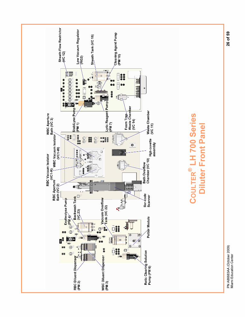
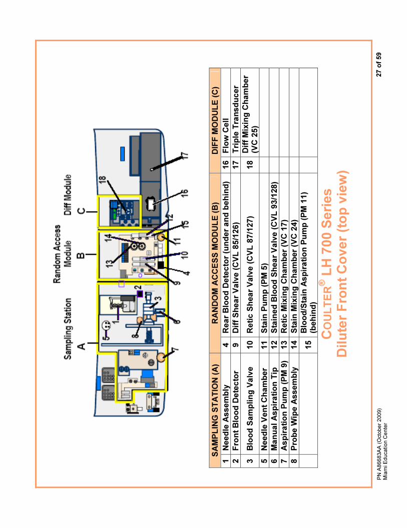
LH 700 Series Diluter Front Panels Diluter Front Cover (top view)
LH SlideMaker Sample Access and Reservoir Module Dispense Module Dispense Probe Mechanism and Rinse Block Slide Transport Module
Common Troubleshooting Fixes
Common Orderable Parts LH 700 Series
Instrument Power Off/On Low Vacuum Low Message Low Vacuum Drifted Message Fluid Leaks Level Sense Message Backwash Tank Not Full Message Probe Messages Rocker Bed Messages Aspiration Messages No Diff Results No Retic Results
LH SlideMaker Dispense Probe Messages Low Vacuum 1 or 2 Messages Shuttle or Truck Vacuum Messages
LH SlideStainer Bath Not Draining Messages Bath Not Filling Messages
As Needed Cleaning Procedures
LH 700 Series LH SlideMaker LH SlideStainer
Optimizing Stain Protocols

PN A86683AA (October 2009) Miami Education Center
vii of xii
Hematopoiesis: The Original Family Tree
Courtesy Johns Hopkins University Press,
The Johns Hopkins Atlas of Human Functional Anatomy, Leon Schlossberg, illustrator
PN A86683AA (October 2009) Miami Education Center
viii of xii
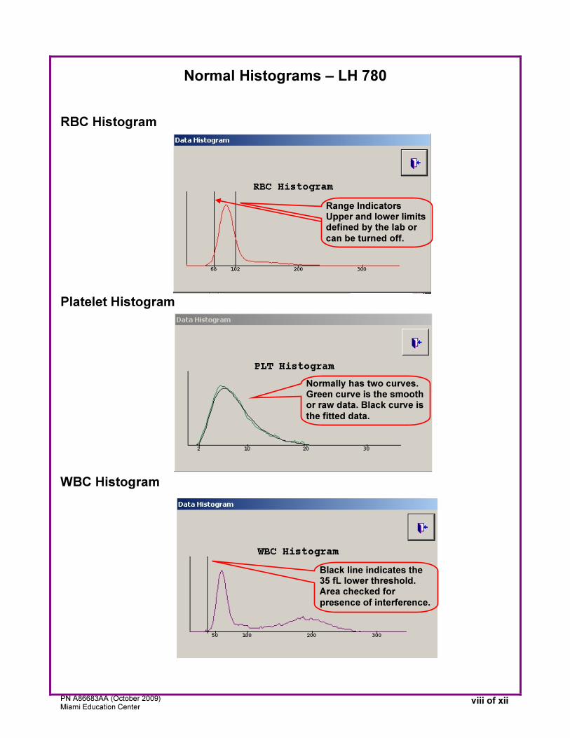
Normal Histograms – LH 780 RBC Histogram Platelet Histogram WBC Histogram
Range Indicators Upper and lower limits defined by the lab or
can be turned off.
Normally has two curves. Green curve is the smooth or raw data. Black curve is
the fitted data.
Black line indicates the 35 fL lower threshold. Area checked for
presence of interference.
PN A86683AA (October 2009) Miami Education Center
ix of xii
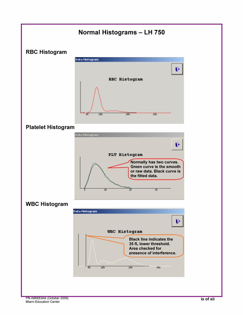
Normal Histograms – LH 750
RBC Histogram
Platelet Histogram WBC Histogram
Normally has two curves. Green curve is the smooth or raw data. Black curve is the fitted data.
Black line indicates the 35 fL lower threshold. Area checked for presence of interference.
PN A86683AA (October 2009) Miami Education Center
x of xii
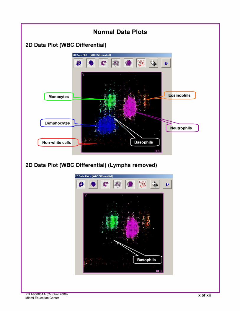
Normal Data Plots 2D Data Plot (WBC Differential) 2D Data Plot (WBC Differential) (Lymphs removed)
Monocytes
Lymphocytes
Non-white cells
Neutrophils
Eosinophils
Basophils
Basophils
PN A86683AA (October 2009) Miami Education Center
xi of xii
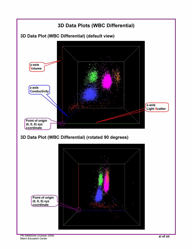
3D Data Plots (WBC Differential) 3D Data Plot (WBC Differential) (default view) 3D Data Plot (WBC Differential) (rotated 90 degrees)
Point of origin (0, 0, 0) xyz coordinate
y-axis
Volume
z-axis Conductivity
x-axis
Light Scatter
Point of origin (0, 0, 0) xyz coordinate
PN A86683AA (October 2009) Miami Education Center
xii of xii
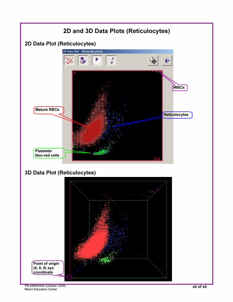
2D and 3D Data Plots (Reticulocytes) 2D Data Plot (Reticulocytes) 3D Data Plot (Reticulocytes)
Mature RBCs
Platelets/ Non-red cells
Reticulocytes
WBCs
Point of origin (0, 0, 0) xyz coordinate
PN A86683AA (October 2009) Miami Education Center
1 of 59
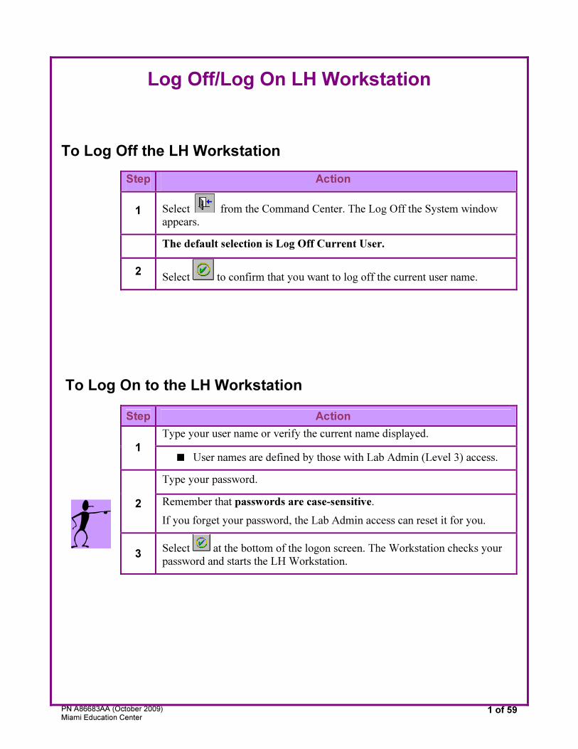
Log Off/Log On LH Workstation
To Log Off the LH Workstation
Step Action
1 Select
from the Command Center. The Log Off the System window
appears.
The default selection is Log Off Current User.
2 Select
to confirm that you want to log off the current user name.
To Log On to the LH Workstation
Step Action
Type your user name or verify the current name displayed.
1 ■ User names are defined by those with Lab Admin (Level 3) access.
Type your password.
2 Remember that passwords are case-sensitive.
If you forget your password, the Lab Admin access can reset it for you.
3 Select
at the bottom of the logon screen. The Workstation checks your
password and starts the LH Workstation.
PN A86683AA (October 2009) Miami Education Center
2 of 59
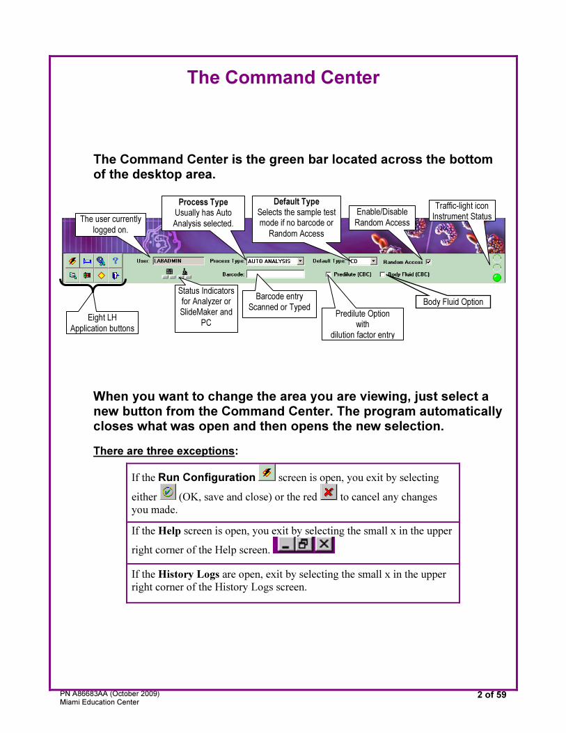
The Command Center
The Command Center is the green bar located across the bottom of the desktop area.
When you want to change the area you are viewing, just select a new button from the Command Center. The program automatically closes what was open and then opens the new selection.
There are three exceptions:
If the Run Configuration screen is open, you exit by selecting
either
(OK, save and close) or the red to cancel any changes
you made.
If the Help screen is open, you exit by selecting the small x in the upper
right corner of the Help screen.
If the History Logs are open, exit by selecting the small x in the upper
right corner of the History Logs screen.
The user currently
logged on.
Body Fluid Option
Eight LH
Application buttons
Status Indicators for Analyzer or SlideMaker and
PC
Barcode entry Scanned or Typed
Predilute Optionwith
dilution factor entry
Process Type
Usually has Auto
Analysis selected.
Default Type
Selects the sample test mode if no barcode or
Random Access
Enable/Disable
Random Access
Traffic-light iconInstrument Status
PN A86683AA (October 2009) Miami Education Center
3 of 59
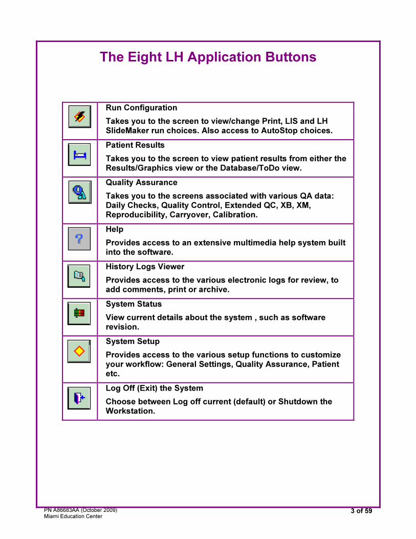
The Eight LH Application Buttons
Run Configuration
Takes you to the screen to view/change Print, LIS and LH SlideMaker run choices. Also access to AutoStop choices.
Patient Results
Takes you to the screen to view patient results from either the Results/Graphics view or the Database/ToDo view.
Quality Assurance
Takes you to the screens associated with various QA data: Daily Checks, Quality Control, Extended QC, XB, XM, Reproducibility, Carryover, Calibration.
Help
Provides access to an extensive multimedia help system built into the software.
History Logs Viewer
Provides access to the various electronic logs for review, to add comments, print or archive.
System Status
View current details about the system , such as software revision.
System Setup
Provides access to the various setup functions to customize your workflow: General Settings, Quality Assurance, Patient etc.
Log Off (Exit) the System
Choose between Log off current (default) or Shutdown the Workstation.
PN A86683AA (October 2009) Miami Education Center
4 of 59
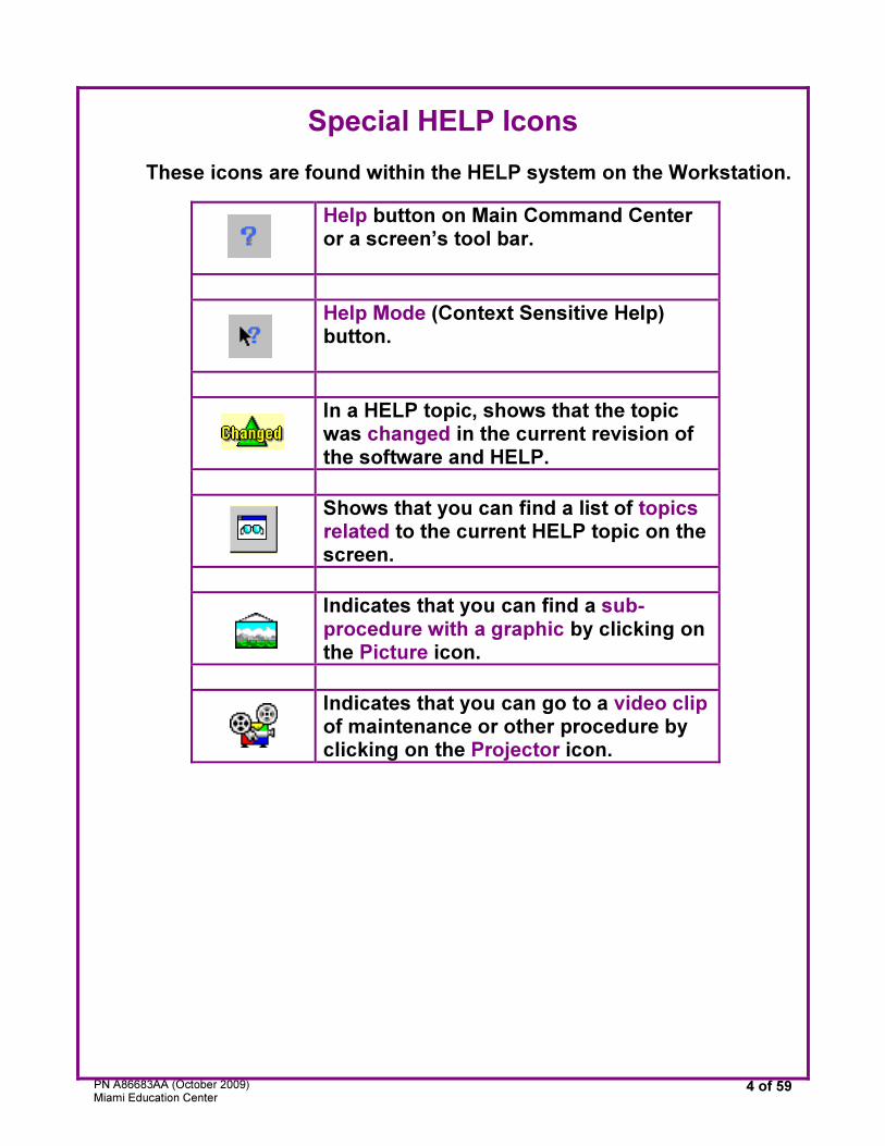
Special HELP Icons
These icons are found within the HELP system on the Workstation.
Help button on Main Command Center or a screen’s tool bar.
Help Mode (Context Sensitive Help) button.
In a HELP topic, shows that the topic was changed in the current revision of the software and HELP.
Shows that you can find a list of topics related to the current HELP topic on the screen.
Indicates that you can find a sub-procedure with a graphic by clicking on the Picture icon.
Indicates that you can go to a video clip of maintenance or other procedure by clicking on the Projector icon.
PN A86683AA (October 2009) Miami Education Center
5 of 59
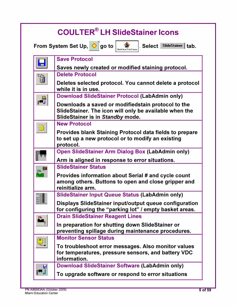
COULTER®
LH SlideStainer Icons
From System Set Up, go to . Select tab.
Save Protocol
Saves newly created or modified staining protocol.
Delete Protocol
Deletes selected protocol. You cannot delete a protocol while it is in use.
Download SlideStainer Protocol (LabAdmin only)
Downloads a saved or modifiedstain protocol to the SlideStainer. The icon will only be available when the SlideStainer is in Standby mode.
New Protocol
Provides blank Staining Protocol data fields to prepare to set up a new protocol or to modify an existing protocol.
Open SlideStainer Arm Dialog Box (LabAdmin only)
Arm is aligned in response to error situations.
SlideStainer Status
Provides information about Serial # and cycle count among others. Buttons to open and close gripper and reinitialize arm.
SlideStainer Input Queue Status (LabAdmin only)
Displays SlideStainer input/output queue configuration for configuring the “parking lot” / empty basket areas.
Drain SlideStainer Reagent Lines
In preparation for shutting down SlideStainer or preventing spillage during maintenance procedures.
Monitor Sensor Status
To troubleshoot error messages. Also monitor values for temperatures, pressure sensors, and battery VDC information.
Download SlideStainer Software (LabAdmin only)
To upgrade software or respond to error situations
PN A86683AA (October 2009) Miami Education Center
6 of 59
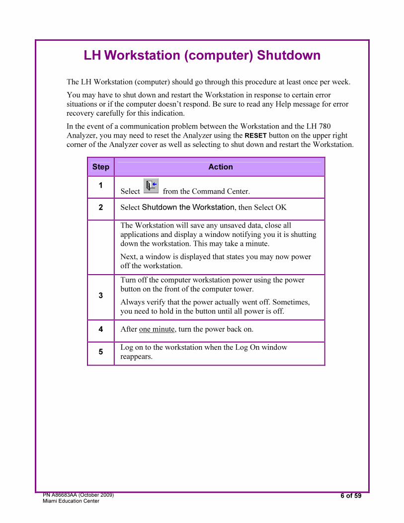
LH Workstation (computer) Shutdown
The LH Workstation (computer) should go through this procedure at least once per week.
You may have to shut down and restart the Workstation in response to certain error
situations or if the computer doesn’t respond. Be sure to read any Help message for error
recovery carefully for this indication.
In the event of a communication problem between the Workstation and the LH 780
Analyzer, you may need to reset the Analyzer using the RESET button on the upper right
corner of the Analyzer cover as well as selecting to shut down and restart the Workstation.
Step Action
1 Select from the Command Center.
2 Select Shutdown the Workstation, then Select OK
The Workstation will save any unsaved data, close all
applications and display a window notifying you it is shutting
down the workstation. This may take a minute.
Next, a window is displayed that states you may now power
off the workstation.
3
Turn off the computer workstation power using the power
button on the front of the computer tower.
Always verify that the power actually went off. Sometimes,
you need to hold in the button until all power is off.
4 After one minute, turn the power back on.
5 Log on to the workstation when the Log On window
reappears.
PN A86683AA (October 2009) Miami Education Center
7 of 59
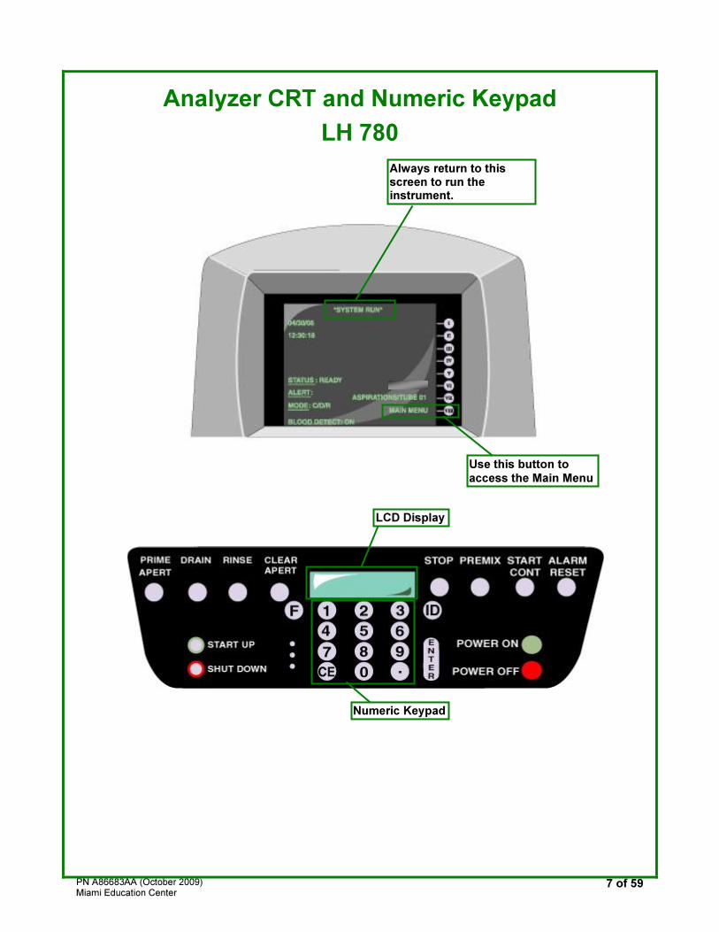
Analyzer CRT and Numeric Keypad
LH 780
LCD Display
Numeric Keypad
Always return to this screen to run the instrument.
Use this button to access the Main Menu
PN A86683AA (October 2009) Miami Education Center
8 of 59
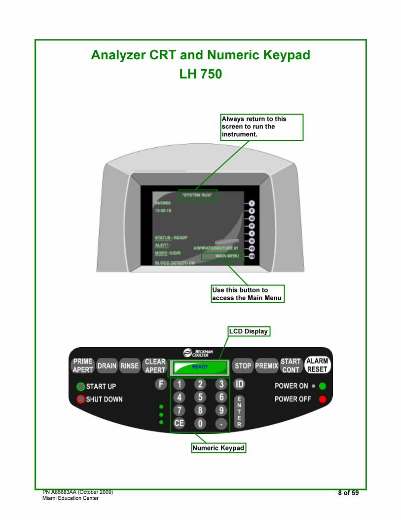
Analyzer CRT and Numeric Keypad
LH 750
LCD Display
Numeric Keypad
Always return to this screen to run the
instrument.
Use this button to
access the Main Menu
PN A86683AA (October 2009) Miami Education Center
9 of 59
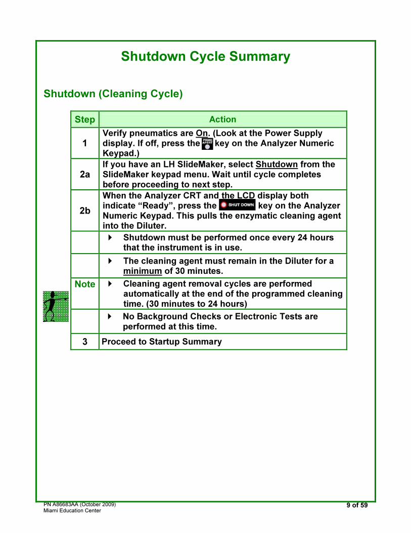
Shutdown Cycle Summary
Shutdown (Cleaning Cycle)
Step Action
1 Verify pneumatics are On. (Look at the Power Supply display. If off, press the key on the Analyzer Numeric Keypad.)
2a If you have an LH SlideMaker, select Shutdown from the SlideMaker keypad menu. Wait until cycle completes before proceeding to next step.
2b
When the Analyzer CRT and the LCD display both indicate “Ready”, press the key on the Analyzer Numeric Keypad. This pulls the enzymatic cleaning agent into the Diluter.
� Shutdown must be performed once every 24 hours
that the instrument is in use.
� The cleaning agent must remain in the Diluter for a
minimum of 30 minutes.
Note � Cleaning agent removal cycles are performed automatically at the end of the programmed cleaning time. (30 minutes to 24 hours)
� No Background Checks or Electronic Tests are
performed at this time.
3 Proceed to Startup Summary
PN A86683AA (October 2009) Miami Education Center
10 of 59
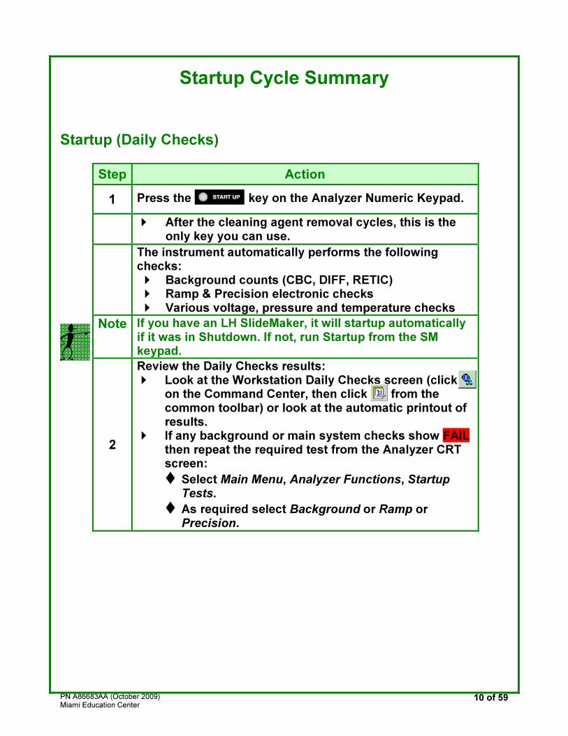
Startup Cycle Summary
Startup (Daily Checks)
Step Action
1 Press the key on the Analyzer Numeric Keypad.
� After the cleaning agent removal cycles, this is the
only key you can use.
The instrument automatically performs the following checks: � Background counts (CBC, DIFF, RETIC) � Ramp & Precision electronic checks � Various voltage, pressure and temperature checks
Note If you have an LH SlideMaker, it will startup automatically if it was in Shutdown. If not, run Startup from the SM keypad.
2
Review the Daily Checks results: � Look at the Workstation Daily Checks screen (click
on the Command Center, then click from the common toolbar) or look at the automatic printout of results.
� If any background or main system checks show FAIL then repeat the required test from the Analyzer CRT screen:
� Select Main Menu, Analyzer Functions, Startup Tests.
� As required select Background or Ramp or Precision.
PN A86683AA (October 2009) Miami Education Center
11 of 59
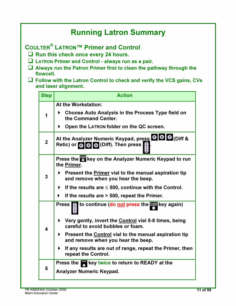
Running Latron Summary
COULTER® LATRON™ Primer and Control
� Run this check once every 24 hours.
� LATRON Primer and Control - always run as a pair.
� Always run the Patron Primer first to clean the pathway through the flowcell.
� Follow with the Latron Control to check and verify the VCS gains, CVs and laser alignment.
Step Action
1
At the Workstation:
� Choose Auto Analysis in the Process Type field on the Command Center.
� Open the LATRON folder on the QC screen.
2 At the Analyzer Numeric Keypad, press (Diff & Retic) or (Diff). Then press .
3
Press the key on the Analyzer Numeric Keypad to run the Primer.
� Present the Primer vial to the manual aspiration tip and remove when you hear the beep.
� If the results are ≤ 500, continue with the Control.
� If the results are > 500, repeat the Primer.
4
Press to continue (do not press the key again)
� Very gently, invert the Control vial 5-8 times, being careful to avoid bubbles or foam.
� Present the Control vial to the manual aspiration tip and remove when you hear the beep.
� If any results are out of range, repeat the Primer, then repeat the Control.
5 Press the key twice to return to READY at the
Analyzer Numeric Keypad.
PN A86683AA (October 2009) Miami Education Center
12 of 59
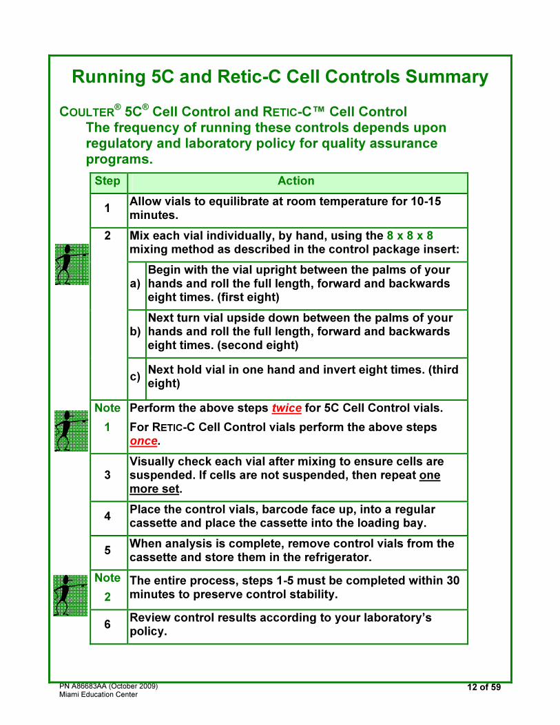
Running 5C and Retic-C Cell Controls Summary
COULTER® 5C® Cell Control and RETIC-C™ Cell Control
The frequency of running these controls depends upon regulatory and laboratory policy for quality assurance programs.
Step Action
1 Allow vials to equilibrate at room temperature for 10-15 minutes.
Mix each vial individually, by hand, using the 8 x 8 x 8 mixing method as described in the control package insert:
a) Begin with the vial upright between the palms of your hands and roll the full length, forward and backwards eight times. (first eight)
b) Next turn vial upside down between the palms of your hands and roll the full length, forward and backwards eight times. (second eight)
2
c) Next hold vial in one hand and invert eight times. (third eight)
Note
1
Perform the above steps twice for 5C Cell Control vials.
For RETIC-C Cell Control vials perform the above steps once.
3 Visually check each vial after mixing to ensure cells are suspended. If cells are not suspended, then repeat one more set.
4 Place the control vials, barcode face up, into a regular cassette and place the cassette into the loading bay.
5 When analysis is complete, remove control vials from the cassette and store them in the refrigerator.
Note
2
The entire process, steps 1-5 must be completed within 30 minutes to preserve control stability.
6 Review control results according to your laboratory’s policy.
PN A86683AA (October 2009) Miami Education Center
13 of 59
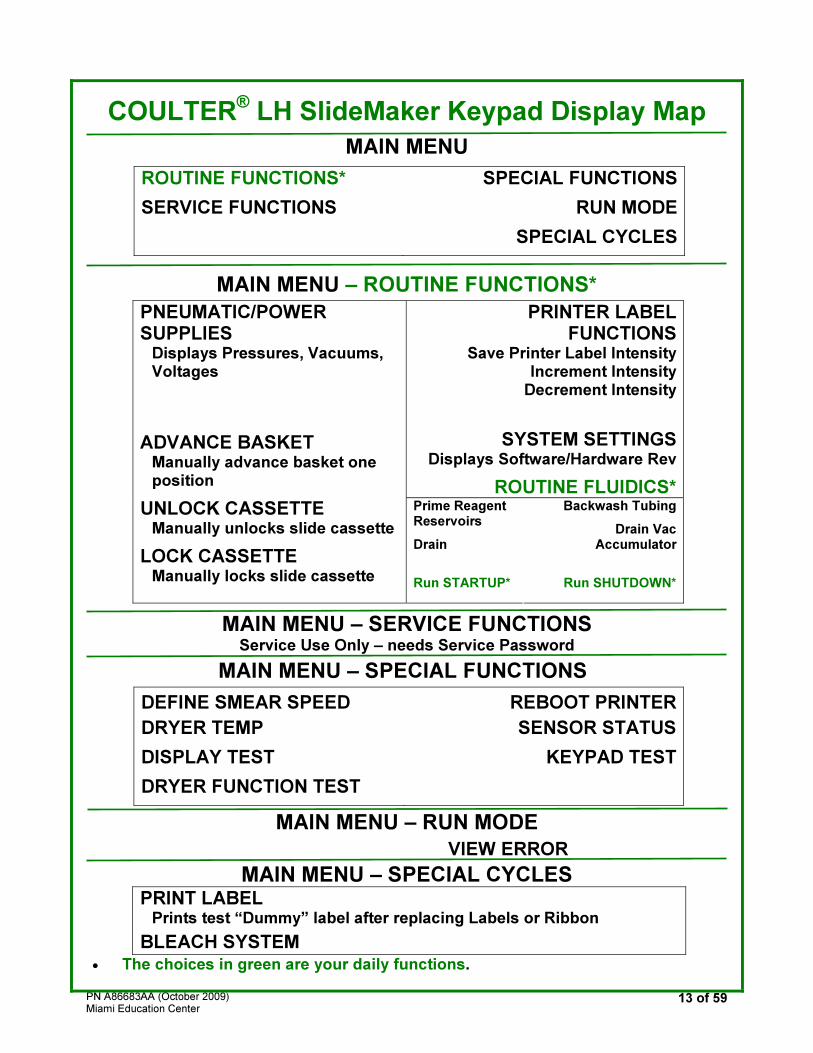
COULTER® LH SlideMaker Keypad Display Map
MAIN MENU
ROUTINE FUNCTIONS*
SERVICE FUNCTIONS
SPECIAL FUNCTIONS
RUN MODE
SPECIAL CYCLES
MAIN MENU – ROUTINE FUNCTIONS*
PRINTER LABELFUNCTIONS
Save Printer Label IntensityIncrement Intensity
Decrement Intensity
SYSTEM SETTINGSDisplays Software/Hardware Rev
ROUTINE FLUIDICS*
PNEUMATIC/POWER SUPPLIES
Displays Pressures, Vacuums, Voltages
ADVANCE BASKET
Manually advance basket one position
UNLOCK CASSETTE Manually unlocks slide cassette
LOCK CASSETTE Manually locks slide cassette
Prime Reagent Reservoirs
Drain
Run STARTUP*
Backwash Tubing
Drain Vac Accumulator
Run SHUTDOWN*
MAIN MENU – SERVICE FUNCTIONS Service Use Only – needs Service Password
MAIN MENU – SPECIAL FUNCTIONS
DEFINE SMEAR SPEED
DRYER TEMP
DISPLAY TEST
DRYER FUNCTION TEST
REBOOT PRINTER
SENSOR STATUS
KEYPAD TEST
MAIN MENU – RUN MODE
VIEW ERROR
MAIN MENU – SPECIAL CYCLES PRINT LABEL
Prints test “Dummy” label after replacing Labels or Ribbon
BLEACH SYSTEM
• The choices in green are your daily functions.

PN A86683AA (October 2009) Miami Education Center
14 of 59
LH SlideMaker Suggested Daily Setup
These checks/setups may be done during the Shutdown cycle, or at any time appropriate for your lab.
LH SlideMaker - only
� Verify that the Slide Cassette is full.
� Check Label and Ribbon supply, replace if necessary. (refer to Help)
� Place up to twelve empty slide baskets in the front and rear tracks. (if no LH SlideStainer)
� Inspect dispense probe and rinse cup and clean if any traces of blood are seen. (refer to Help)
Once the system is operating automatically, do not grab slides prematurely, this can cause jams and resets. Let the SlideMaker do its job.
PN A86683AA (October 2009) Miami Education Center
15 of 59
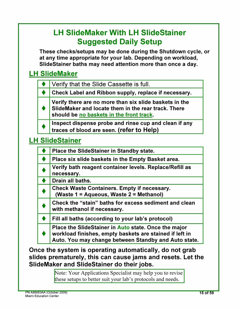
LH SlideMaker With LH SlideStainer Suggested Daily Setup
These checks/setups may be done during the Shutdown cycle, or at any time appropriate for your lab. Depending on workload, SlideStainer baths may need attention more than once a day.
LH SlideMaker
� Verify that the Slide Cassette is full.
� Check Label and Ribbon supply, replace if necessary.
�
Verify there are no more than six slide baskets in the SlideMaker and locate them in the rear track. There should be no baskets in the front track.
� Inspect dispense probe and rinse cup and clean if any
traces of blood are seen. (refer to Help)
LH SlideStainer
� Place the SlideStainer in Standby state.
� Place six slide baskets in the Empty Basket area.
� Verify bath reagent container levels. Replace/Refill as necessary.
� Drain all baths.
� Check Waste Containers. Empty if necessary.
(Waste 1 = Aqueous, Waste 2 = Methanol)
� Check the “stain” baths for excess sediment and clean with methanol if necessary.
� Fill all baths (according to your lab’s protocol)
�
Place the SlideStainer in Auto state. Once the major workload finishes, empty baskets are stained if left in Auto. You may change between Standby and Auto state.
Once the system is operating automatically, do not grab slides prematurely, this can cause jams and resets. Let the SlideMaker and SlideStainer do their jobs.
Note: Your Applications Specialist may help you to revise
these setups to better suit your lab’s protocols and needs.
PN A86683AA (October 2009) Miami Education Center
16 of 59
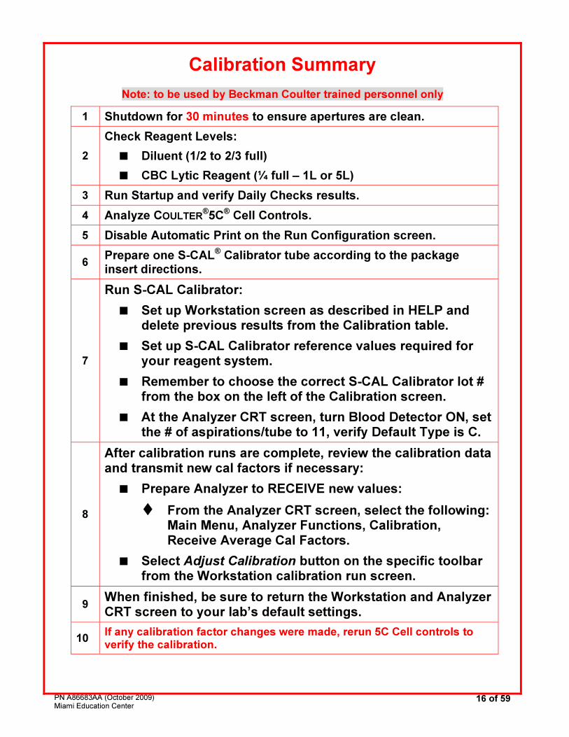
Calibration Summary
Note: to be used by Beckman Coulter trained personnel only
1 Shutdown for 30 minutes to ensure apertures are clean.
2
Check Reagent Levels:
� Diluent (1/2 to 2/3 full)
� CBC Lytic Reagent (¼ full – 1L or 5L)
3 Run Startup and verify Daily Checks results.
4 Analyze COULTER®5C® Cell Controls.
5 Disable Automatic Print on the Run Configuration screen.
6 Prepare one S-CAL® Calibrator tube according to the package insert directions.
7
Run S-CAL Calibrator:
� Set up Workstation screen as described in HELP and delete previous results from the Calibration table.
� Set up S-CAL Calibrator reference values required for your reagent system.
� Remember to choose the correct S-CAL Calibrator lot # from the box on the left of the Calibration screen.
� At the Analyzer CRT screen, turn Blood Detector ON, set the # of aspirations/tube to 11, verify Default Type is C.
8
After calibration runs are complete, review the calibration data and transmit new cal factors if necessary:
� Prepare Analyzer to RECEIVE new values:
� From the Analyzer CRT screen, select the following: Main Menu, Analyzer Functions, Calibration, Receive Average Cal Factors.
� Select Adjust Calibration button on the specific toolbar from the Workstation calibration run screen.
9 When finished, be sure to return the Workstation and Analyzer CRT screen to your lab’s default settings.
10 If any calibration factor changes were made, rerun 5C Cell controls to verify the calibration.
PN A86683AA (October 2009) Miami Education Center
17 of 59
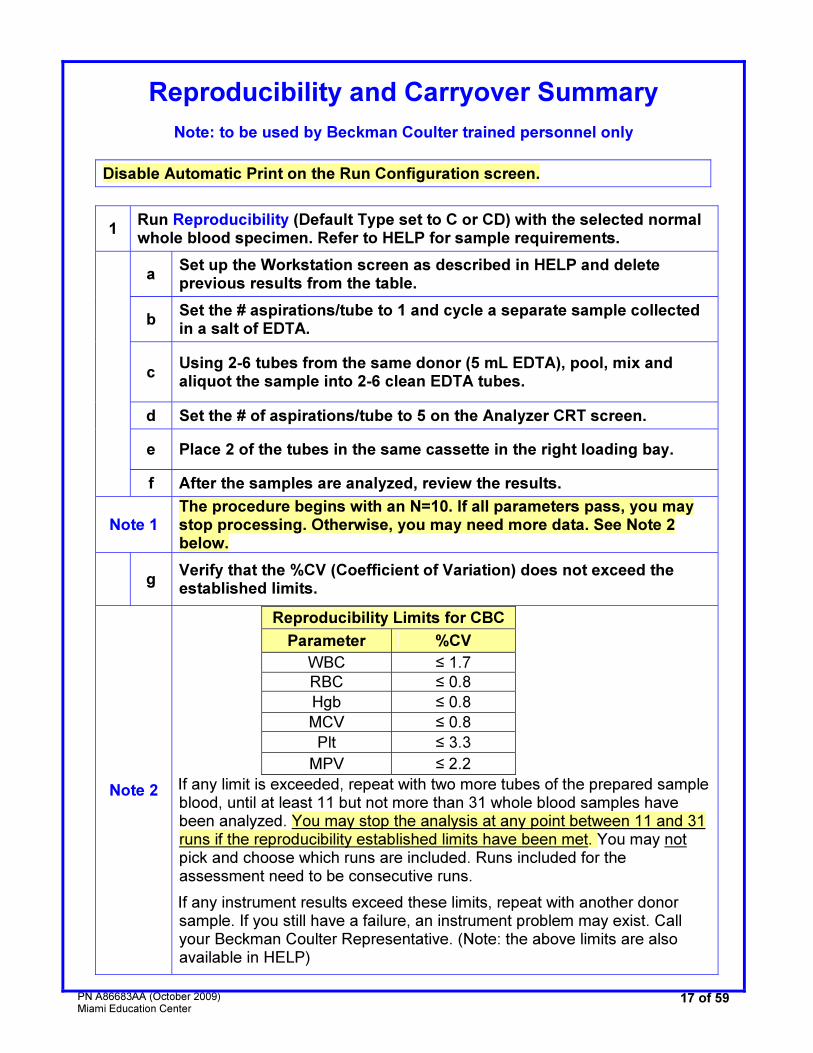
Reproducibility and Carryover Summary
Note: to be used by Beckman Coulter trained personnel only
Disable Automatic Print on the Run Configuration screen.
1 Run Reproducibility (Default Type set to C or CD) with the selected normal whole blood specimen. Refer to HELP for sample requirements.
a Set up the Workstation screen as described in HELP and delete previous results from the table.
b Set the # aspirations/tube to 1 and cycle a separate sample collected in a salt of EDTA.
c Using 2-6 tubes from the same donor (5 mL EDTA), pool, mix and aliquot the sample into 2-6 clean EDTA tubes.
d Set the # of aspirations/tube to 5 on the Analyzer CRT screen.
e Place 2 of the tubes in the same cassette in the right loading bay.
f After the samples are analyzed, review the results.
Note 1 The procedure begins with an N=10. If all parameters pass, you may stop processing. Otherwise, you may need more data. See Note 2 below.
g Verify that the %CV (Coefficient of Variation) does not exceed the established limits.
Note 2
Reproducibility Limits for CBC
Parameter %CV
WBC ≤ 1.7
RBC ≤ 0.8
Hgb ≤ 0.8
MCV ≤ 0.8
Plt ≤ 3.3
MPV ≤ 2.2
If any limit is exceeded, repeat with two more tubes of the prepared sample blood, until at least 11 but not more than 31 whole blood samples have been analyzed. You may stop the analysis at any point between 11 and 31 runs if the reproducibility established limits have been met. You may not pick and choose which runs are included. Runs included for the assessment need to be consecutive runs.
If any instrument results exceed these limits, repeat with another donor sample. If you still have a failure, an instrument problem may exist. Call your Beckman Coulter Representative. (Note: the above limits are also available in HELP)
PN A86683AA (October 2009) Miami Education Center
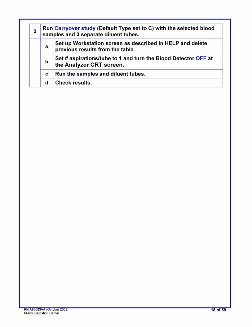
18 of 59
2 Run Carryover study (Default Type set to C) with the selected blood samples and 3 separate diluent tubes.
a Set up Workstation screen as described in HELP and delete previous results from the table.
b Set # aspirations/tube to 1 and turn the Blood Detector OFF at
the Analyzer CRT screen.
c Run the samples and diluent tubes.
d Check results.
PN A86683AA (October 2009) Miami Education Center
19 of 59
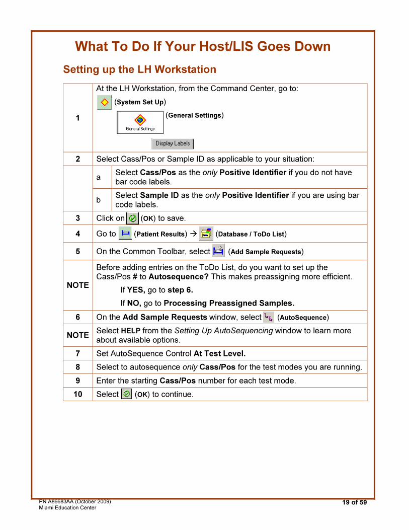
What To Do If Your Host/LIS Goes Down
Setting up the LH Workstation
1
At the LH Workstation, from the Command Center, go to:
(System Set Up)
(General Settings)
2 Select Cass/Pos or Sample ID as applicable to your situation:
a Select Cass/Pos as the only Positive Identifier if you do not have bar code labels.
b Select Sample ID as the only Positive Identifier if you are using bar code labels.
3 Click on (OK) to save.
4 Go to (Patient Results) � (Database / ToDo List)
5 On the Common Toolbar, select (Add Sample Requests)
NOTE
Before adding entries on the ToDo List, do you want to set up the Cass/Pos # to Autosequence? This makes preassigning more efficient.
If YES, go to step 6.
If NO, go to Processing Preassigned Samples.
6 On the Add Sample Requests window, select (AutoSequence)
NOTE Select HELP from the Setting Up AutoSequencing window to learn more about available options.
7 Set AutoSequence Control At Test Level.
8 Select to autosequence only Cass/Pos for the test modes you are running.
9 Enter the starting Cass/Pos number for each test mode.
10 Select (OK) to continue.
PN A86683AA (October 2009) Miami Education Center
20 of 59
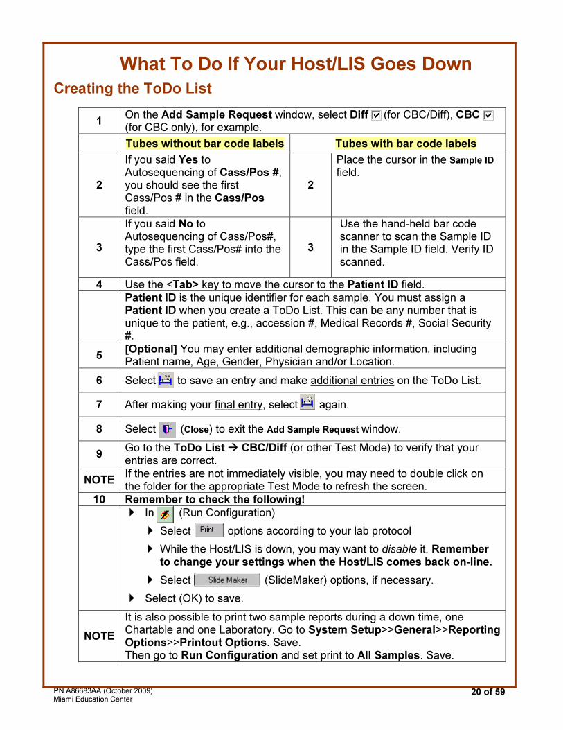
What To Do If Your Host/LIS Goes Down
Creating the ToDo List
1 On the Add Sample Request window, select Diff (for CBC/Diff), CBC (for CBC only), for example.
Tubes without bar code labels Tubes with bar code labels
2
If you said Yes to Autosequencing of Cass/Pos #, you should see the first Cass/Pos # in the Cass/Pos field.
2
Place the cursor in the Sample ID
field.
3
If you said No to Autosequencing of Cass/Pos#, type the first Cass/Pos# into the Cass/Pos field.
3
Use the hand-held bar code scanner to scan the Sample ID in the Sample ID field. Verify ID scanned.
4 Use the <Tab> key to move the cursor to the Patient ID field.
Patient ID is the unique identifier for each sample. You must assign a Patient ID when you create a ToDo List. This can be any number that is unique to the patient, e.g., accession #, Medical Records #, Social Security #.
5 [Optional] You may enter additional demographic information, including Patient name, Age, Gender, Physician and/or Location.
6 Select to save an entry and make additional entries on the ToDo List.
7 After making your final entry, select again.
8 Select (Close) to exit the Add Sample Request window.
9 Go to the ToDo List � CBC/Diff (or other Test Mode) to verify that your entries are correct.
NOTE If the entries are not immediately visible, you may need to double click on the folder for the appropriate Test Mode to refresh the screen.
10 Remember to check the following!
� In (Run Configuration)
� Select options according to your lab protocol
� While the Host/LIS is down, you may want to disable it. Remember to change your settings when the Host/LIS comes back on-line.
� Select (SlideMaker) options, if necessary.
� Select (OK) to save.
NOTE
It is also possible to print two sample reports during a down time, one Chartable and one Laboratory. Go to System Setup>>General>>Reporting Options>>Printout Options. Save. Then go to Run Configuration and set print to All Samples. Save.

PN A86683AA (October 2009) Miami Education Center
21 of 59
IQAP/eIQAP General Information
Important Points to Remember When Setting Up eIQAP
Make note of the following:
Instrument IQAP Participant # Serial Number System ID
Number to Call for Help: 800-526-7694 (USA and Canada)
PN A86683AA (October 2009) Miami Education Center
22 of 59
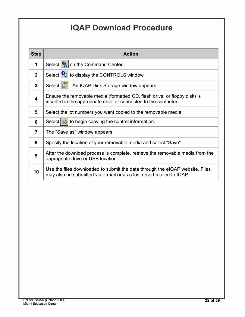
IQAP Download Procedure
Step Action
1 Select on the Command Center.
2 Select to display the CONTROLS window.
3 Select . An IQAP Disk Storage window appears.
4 Ensure the removable media (formatted CD, flash drive, or floppy disk) is inserted in the appropriate drive or connected to the computer.
5 Select the lot numbers you want copied to the removable media.
6 Select to begin copying the control information.
7 The "Save as" window appears.
8 Specify the location of your removable media and select "Save".
9 After the download process is complete, retrieve the removable media from the appropriate drive or USB location
10 Use the files downloaded to submit the data through the eIQAP website. Files may also be submitted via e-mail or as a last resort mailed to IQAP.
PN A86683AA (October 2009) Miami Education Center
23 of 59
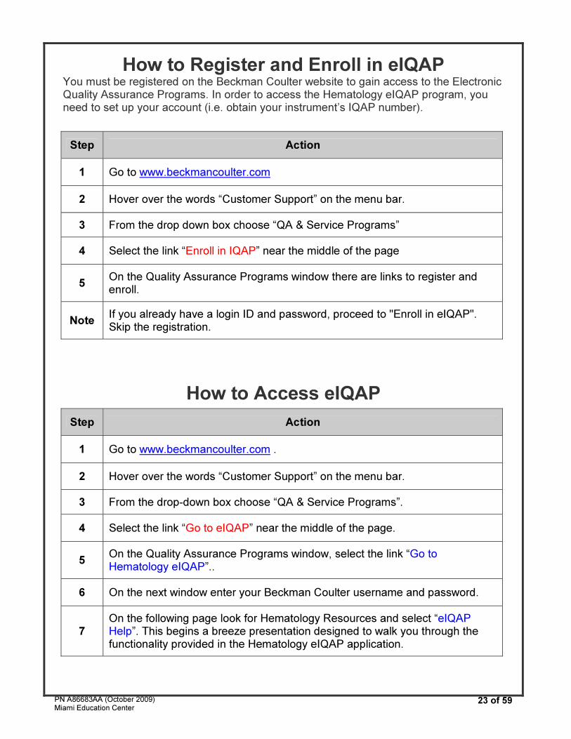
How to Register and Enroll in eIQAP You must be registered on the Beckman Coulter website to gain access to the Electronic Quality Assurance Programs. In order to access the Hematology eIQAP program, you need to set up your account (i.e. obtain your instrument’s IQAP number).
How to Access eIQAP
Step Action
1 Go to www.beckmancoulter.com
2 Hover over the words “Customer Support” on the menu bar.
3 From the drop down box choose “QA & Service Programs”
4 Select the link “Enroll in IQAP” near the middle of the page
5 On the Quality Assurance Programs window there are links to register and enroll.
Note If you already have a login ID and password, proceed to "Enroll in eIQAP". Skip the registration.
Step Action
1 Go to www.beckmancoulter.com .
2 Hover over the words “Customer Support” on the menu bar.
3 From the drop-down box choose “QA & Service Programs”.
4 Select the link “Go to eIQAP” near the middle of the page.
5 On the Quality Assurance Programs window, select the link “Go to Hematology eIQAP”..
6 On the next window enter your Beckman Coulter username and password.
7 On the following page look for Hematology Resources and select “eIQAP Help”. This begins a breeze presentation designed to walk you through the functionality provided in the Hematology eIQAP application.
PN A86683AA (October 2009) Miami Education Center
24 of 59
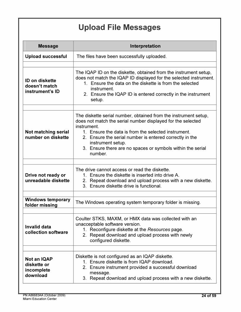
Upload File Messages
Message Interpretation
Upload successful The files have been successfully uploaded.
ID on diskette doesn’t match instrument’s ID
The IQAP ID on the diskette, obtained from the instrument setup, does not match the IQAP ID displayed for the selected instrument.
1. Ensure the data on the diskette is from the selected instrument.
2. Ensure the IQAP ID is entered correctly in the instrument setup.
Not matching serial number on diskette
The diskette serial number, obtained from the instrument setup, does not match the serial number displayed for the selected instrument.
1. Ensure the data is from the selected instrument. 2. Ensure the serial number is entered correctly in the
instrument setup. 3. Ensure there are no spaces or symbols within the serial
number.
Drive not ready or unreadable diskette
The drive cannot access or read the diskette. 1. Ensure the diskette is inserted into drive A. 2. Repeat download and upload process with a new diskette. 3. Ensure diskette drive is functional.
Windows temporary folder missing
The Windows operating system temporary folder is missing.
Invalid data collection software
Coulter STKS, MAXM, or HMX data was collected with an unacceptable software version.
1. Reconfigure diskette at the Resources page. 2. Repeat download and upload process with newly
configured diskette.
Not an IQAP diskette or incomplete download
Diskette is not configured as an IQAP diskette. 1. Ensure diskette is from IQAP download. 2. Ensure instrument provided a successful download
message. 3. Repeat download and upload process with a new diskette.
PN A86683AA (October 2009) Miami Education Center
25 of 59
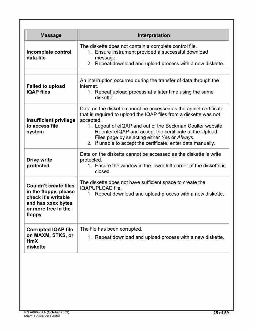
Message Interpretation
Incomplete control data file
The diskette does not contain a complete control file. 1. Ensure instrument provided a successful download
message. 2. Repeat download and upload process with a new diskette.
Failed to upload IQAP files
An interruption occurred during the transfer of data through the internet.
1. Repeat upload process at a later time using the same diskette.
Insufficient privilege to access file system
Data on the diskette cannot be accessed as the applet certificate that is required to upload the IQAP files from a diskette was not accepted.
1. Logout of eIQAP and out of the Beckman Coulter website. Reenter eIQAP and accept the certificate at the Upload Files page by selecting either Yes or Always.
2. If unable to accept the certificate, enter data manually.
Drive write protected
Data on the diskette cannot be accessed as the diskette is write protected.
1. Ensure the window in the lower left corner of the diskette is closed.
Couldn’t create files in the floppy, please check it’s writable and has xxxx bytes or more free in the floppy
The diskette does not have sufficient space to create the IQAPUPLOAD file.
1. Repeat download and upload process with a new diskette.
Corrupted IQAP file on MAXM, STKS, or HmX diskette
The file has been corrupted.
1. Repeat download and upload process with a new diskette.
PN
A86683A
A (
Octo
ber
2009)
Mia
mi E
ducation C
ente
r 26
of
59
CO
UL
TE
R® L
H 7
00
Se
rie
s
Dilu
ter
Fro
nt
Pa
ne
l
PN
A86683A
A (
Octo
ber
2009)
Mia
mi E
ducation C
ente
r 27
of
59
CO
UL
TE
R® L
H 7
00
Se
rie
s
Dilu
ter
Fro
nt
Co
ve
r (t
op
vie
w)
SA
MP
LIN
G S
TA
TIO
N (
A)
RA
ND
OM
AC
CE
SS
MO
DU
LE
(B
) D
IFF
MO
DU
LE
(C
)
1
Nee
dle
As
se
mb
ly
4
Re
ar
Blo
od
De
tec
tor
(un
de
r a
nd
be
hin
d)
16
Flo
w C
ell
2
Fro
nt
Blo
od
De
tec
tor
9
Dif
f S
he
ar
Valv
e (
CV
L 8
5/1
26
) 17
Tri
ple
Tra
nsd
ucer
3
Blo
od
Sa
mp
lin
g V
alv
e
10
Re
tic
Sh
ea
r V
alv
e (
CV
L 8
7/1
27
) 18
Dif
f M
ixin
g C
ham
ber
(VC
25)
5
Nee
dle
Ve
nt
Ch
am
ber
11
Sta
in P
um
p (
PM
5)
6
Ma
nu
al
As
pir
ati
on
Tip
1
2S
tain
ed
Blo
od
Sh
ea
r V
alv
e (
CV
L 9
3/1
28)
7
As
pir
ati
on
Pu
mp
(P
M 9
) 1
3R
eti
c M
ixin
g C
ha
mb
er
(VC
17
)
8
Pro
be
Wip
e A
ss
em
bly
1
4S
tain
Mix
ing
Ch
am
ber
(VC
24
)
15
Blo
od
/Sta
in A
sp
ira
tio
n P
um
p (
PM
11
) (b
eh
ind
)
PN
A86683A
A (
Octo
ber
2009)
Mia
mi E
ducation C
ente
r 28
of
59
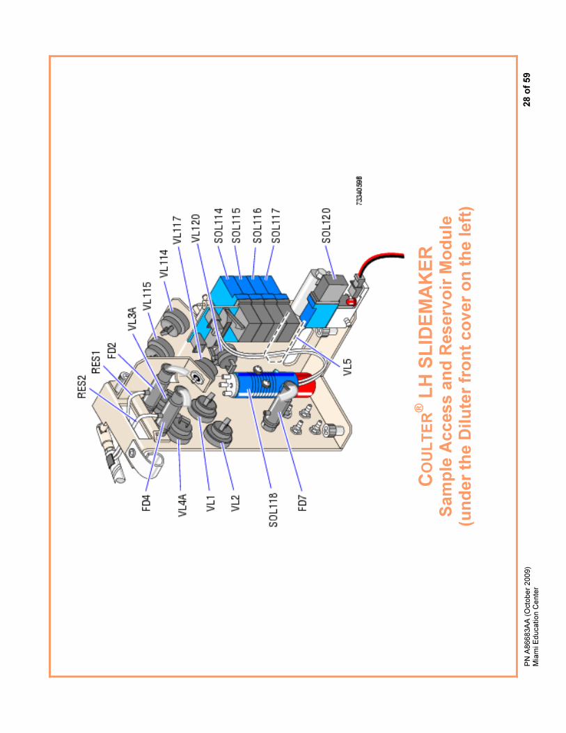
CO
UL
TE
R® L
H S
LID
EM
AK
ER
S
am
ple
Access a
nd
Reserv
oir
Mo
du
le
(un
der
the D
ilu
ter
fro
nt
co
ver
on
th
e l
eft
)
PN
A86683A
A (
Octo
ber
2009)
Mia
mi E
ducation C
ente
r 29
of
59
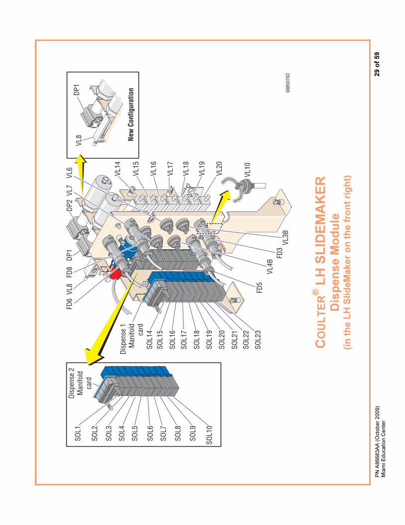
C
OU
LT
ER® L
H S
LID
EM
AK
ER
D
isp
en
se M
od
ule
(i
n t
he L
H S
lid
eM
aker
on
th
e f
ron
t ri
gh
t)
SOL1
SOL2
SOL3
SOL4
SOL5
SOL6
SOL7
SOL8
SOL9
SOL1
0
Disp
ense
2M
anifo
ldca
rd
Disp
ense
1M
anifo
ldca
rdSO
L14
SOL1
5
SOL1
6
SOL1
7
SOL1
8
SOL1
9
SOL2
0
SOL2
1
SOL2
2
SOL2
3FD
5VL
4BFD
3VL
3B
VL10
VL14
VL15
VL16
VL17
VL18
VL19
VL20
FD6
VL8
FD8
DP1
VL7
6985
076D
DP2
VL8
DP1
VL6
New
Con
figur
atio
n
PN
A86683A
A (
Octo
ber
2009)
Mia
mi E
ducation C
ente
r 30
of
59
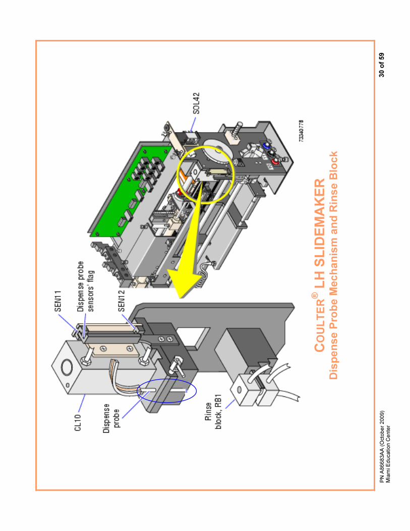
CO
UL
TE
R® L
H S
LID
EM
AK
ER
D
isp
en
se
Pro
be
Me
ch
an
ism
an
d R
ins
e B
loc
k
PN
A86683A
A (
Octo
ber
2009)
Mia
mi E
ducation C
ente
r 31
of
59
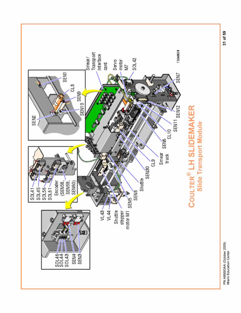
CO
UL
TE
R® L
H S
LID
EM
AK
ER
S
lid
e T
ran
sp
ort
Mo
du
le

PN A86683AA (October 2009) Miami Education Center
32 of 59
Common Troubleshooting Fixes
Common Orderable Parts
Fluidics
Low Vacuum Low Message
Low Vacuum Drifted Message
Fluid Leaks
Level Sense Message
Backwash Tank Not Full Errors
Mechanical
Probe Errors
Aspiration Errors
Rockerbed Errors
Results
No Diff Results
No Retic Results
LH SlideMaker
Dispense Probe Errors
Vacuum Errors
LH SlideStainer
Bath Not Draining Errors
Bath Not Filling Errors
PN A86683AA (October 2009) Miami Education Center
33 of 59
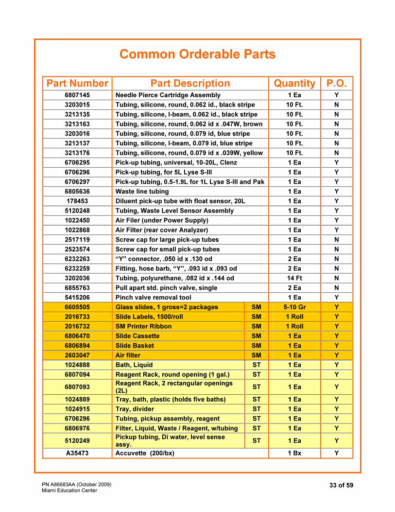
Common Orderable Parts
Part Number Part Description Quantity P.O.6807145 Needle Pierce Cartridge Assembly 1 Ea Y
3203015 Tubing, silicone, round, 0.062 id., black stripe 10 Ft. N
3213135 Tubing, silicone, I-beam, 0.062 id., black stripe 10 Ft. N
3213163 Tubing, silicone, round, 0.062 id x .047W, brown 10 Ft. N
3203016 Tubing, silicone, round, 0.079 id, blue stripe 10 Ft. N
3213137 Tubing, silicone, I-beam, 0.079 id, blue stripe 10 Ft. N
3213176 Tubing, silicone, round, 0.079 id x .039W, yellow 10 Ft. N
6706295 Pick-up tubing, universal, 10-20L, Clenz 1 Ea Y
6706296 Pick-up tubing, for 5L Lyse S-III 1 Ea Y
6706297 Pick-up tubing, 0.5-1.9L for 1L Lyse S-III and Pak 1 Ea Y
6805636 Waste line tubing 1 Ea Y
178453 Diluent pick-up tube with float sensor, 20L 1 Ea Y
5120248 Tubing, Waste Level Sensor Assembly 1 Ea Y
1022450 Air Filer (under Power Supply) 1 Ea Y
1022868 Air Filter (rear cover Analyzer) 1 Ea Y
2517119 Screw cap for large pick-up tubes 1 Ea N
2523574 Screw cap for small pick-up tubes 1 Ea N
6232263 “Y” connector, .050 id x .130 od 2 Ea N
6232259 Fitting, hose barb, “Y”, .093 id x .093 od 2 Ea N
3202036 Tubing, polyurethane, .082 id x .144 od 14 Ft N
6855763 Pull apart std. pinch valve, single 2 Ea N
5415206 Pinch valve removal tool 1 Ea Y
6605505 Glass slides, 1 gross=2 packages SM 5-10 Gr Y
2016733 Slide Labels, 1500/roll SM 1 Roll Y
2016732 SM Printer Ribbon SM 1 Roll Y
6806470 Slide Cassette SM 1 Ea Y
6806894 Slide Basket SM 1 Ea Y
2603047 Air filter SM 1 Ea Y
1024888 Bath, Liquid ST 1 Ea Y
6807094 Reagent Rack, round opening (1 gal.) ST 1 Ea Y
6807093 Reagent Rack, 2 rectangular openings (2L)
ST 1 Ea Y
1024889 Tray, bath, plastic (holds five baths) ST 1 Ea Y
1024915 Tray, divider ST 1 Ea Y
6706296 Tubing, pickup assembly, reagent ST 1 Ea Y
6806976 Filter, Liquid, Waste / Reagent, w/tubing ST 1 Ea Y
5120249 Pickup tubing, Di water, level sense assy.
ST 1 Ea Y
A35473 Accuvette (200/bx) 1 Bx Y
PN A86683AA (October 2009) Miami Education Center
34 of 59
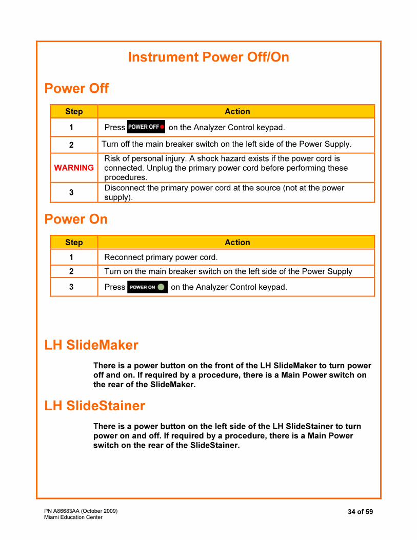
Instrument Power Off/On
Power Off
Step Action
1 Press on the Analyzer Control keypad.
2 Turn off the main breaker switch on the left side of the Power Supply.
WARNING Risk of personal injury. A shock hazard exists if the power cord is connected. Unplug the primary power cord before performing these procedures.
3 Disconnect the primary power cord at the source (not at the power supply).
Power On
Step Action
1 Reconnect primary power cord.
2 Turn on the main breaker switch on the left side of the Power Supply
3 Press on the Analyzer Control keypad.
LH SlideMaker
There is a power button on the front of the LH SlideMaker to turn power off and on. If required by a procedure, there is a Main Power switch on the rear of the SlideMaker.
LH SlideStainer
There is a power button on the left side of the LH SlideStainer to turn power on and off. If required by a procedure, there is a Main Power switch on the rear of the SlideStainer.
PN A86683AA (October 2009) Miami Education Center
35 of 59
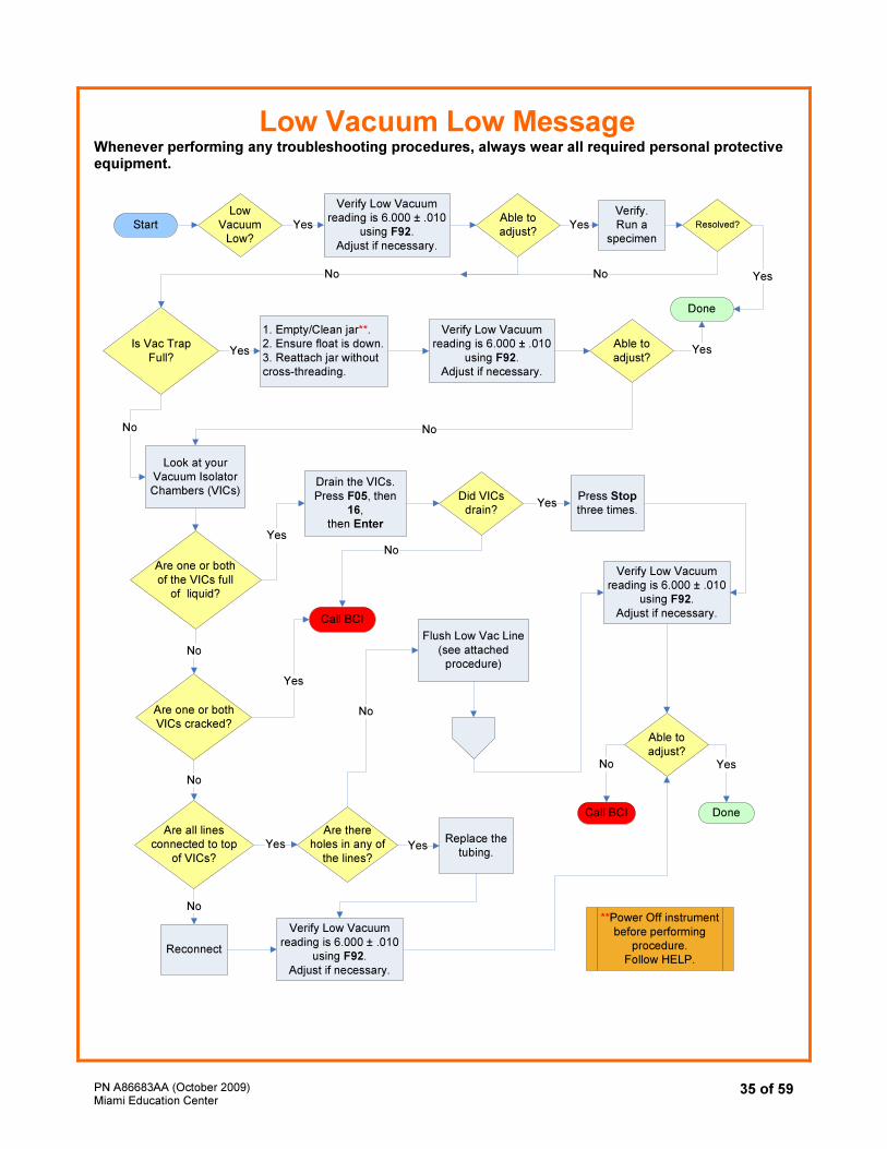
Low Vacuum Low Message Whenever performing any troubleshooting procedures, always wear all required personal protective equipment.
Low
Vacuum
Low?
Start Yes
1. Empty/Clean jar**.
2. Ensure float is down.
3. Reattach jar without
cross-threading.
Verify Low Vacuum
reading is 6.000 ± .010
using F92.
Adjust if necessary.
Is Vac Trap
Full?
Call BCI
Yes
YesNo
No
Done
Yes
Look at your
Vacuum Isolator
Chambers (VICs)
Yes
No
No
Are one or both
of the VICs full
of liquid?
No
Yes
Yes
Are one or both
VICs cracked?
Call BCI
Did VICs
drain?
Drain the VICs.
Press F05, then
16,
then Enter
Press Stop
three times.
Verify Low Vacuum
reading is 6.000 ± .010
using F92.
Adjust if necessary.
Are all lines
connected to top
of VICs?
Are there
holes in any of
the lines?
Reconnect
Replace the
tubing.
No
Verify Low Vacuum
reading is 6.000 ± .010
using F92.
Adjust if necessary.
Yes Yes
**Power Off instrument
before performing
procedure.
Follow HELP.
Able to
adjust?
Verify.
Run a
specimen
Verify Low Vacuum
reading is 6.000 ± .010
using F92.
Adjust if necessary.
YesAble to
adjust?
Flush Low Vac Line
(see attached
procedure)
Able to
adjust?
Done
No
No
No
Resolved?
Yes
No
PN A86683AA (October 2009) Miami Education Center
36 of 59
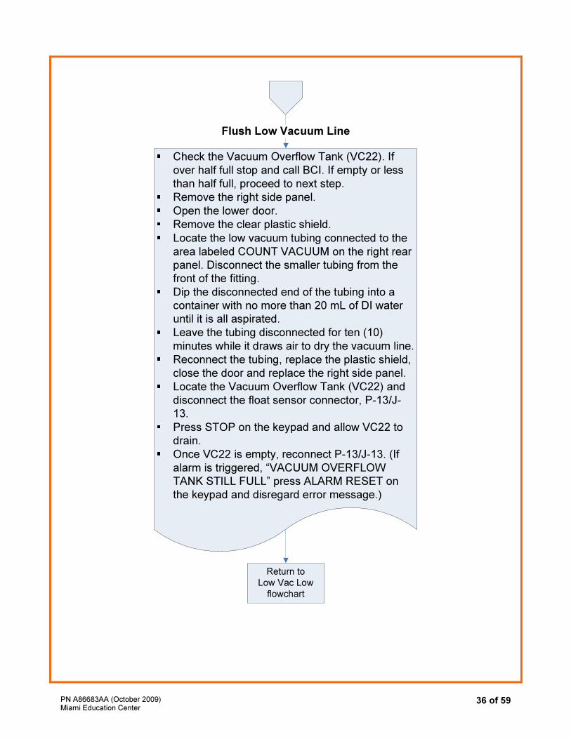
Check the Vacuum Overflow Tank (VC22). If
over half full stop and call BCI. If empty or less
than half full, proceed to next step.
Remove the right side panel.
Open the lower door.
Remove the clear plastic shield.
Locate the low vacuum tubing connected to the
area labeled COUNT VACUUM on the right rear
panel. Disconnect the smaller tubing from the
front of the fitting.
Dip the disconnected end of the tubing into a
container with no more than 20 mL of DI water
until it is all aspirated.
Leave the tubing disconnected for ten (10)
minutes while it draws air to dry the vacuum line.
Reconnect the tubing, replace the plastic shield,
close the door and replace the right side panel.
Locate the Vacuum Overflow Tank (VC22) and
disconnect the float sensor connector, P-13/J-
13.
Press STOP on the keypad and allow VC22 to
drain.
Once VC22 is empty, reconnect P-13/J-13. (If
alarm is triggered, “VACUUM OVERFLOW
TANK STILL FULL” press ALARM RESET on
the keypad and disregard error message.)
Flush Low Vacuum Line
Return to
Low Vac Low
flowchart
PN A86683AA (October 2009) Miami Education Center
37 of 59
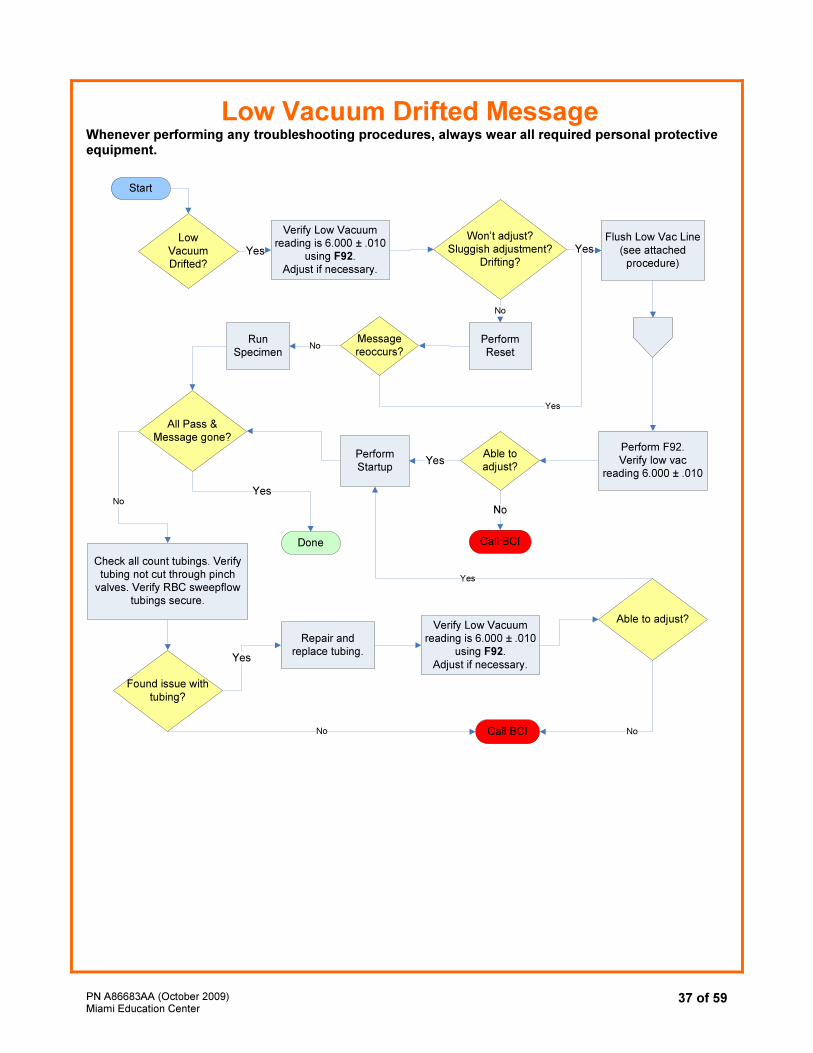
Low Vacuum Drifted Message Whenever performing any troubleshooting procedures, always wear all required personal protective equipment.
Low
Vacuum Drifted?
No
Yes
Won’t adjust? Sluggish adjustment?
Drifting?
Yes
Yes
Yes
All Pass &Message gone?
Perform Startup
Start
Verify Low Vacuumreading is 6.000 ± .010
using F92.Adjust if necessary.
Perform F92.Verify low vac
reading 6.000 ± .010
Call BCIDone
Check all count tubings. Verify tubing not cut through pinch
valves. Verify RBC sweepflow tubings secure.
Call BCI
Found issue with
tubing?
Yes
Able to adjust?
Flush Low Vac Line
(see attached procedure)
Repair and replace tubing.
Able to adjust?Verify Low Vacuum
reading is 6.000 ± .010 using F92.
Adjust if necessary.
No
No No
Perform Reset
Message reoccurs?
Yes
No
Yes
Run Specimen
No
PN A86683AA (October 2009) Miami Education Center
38 of 59
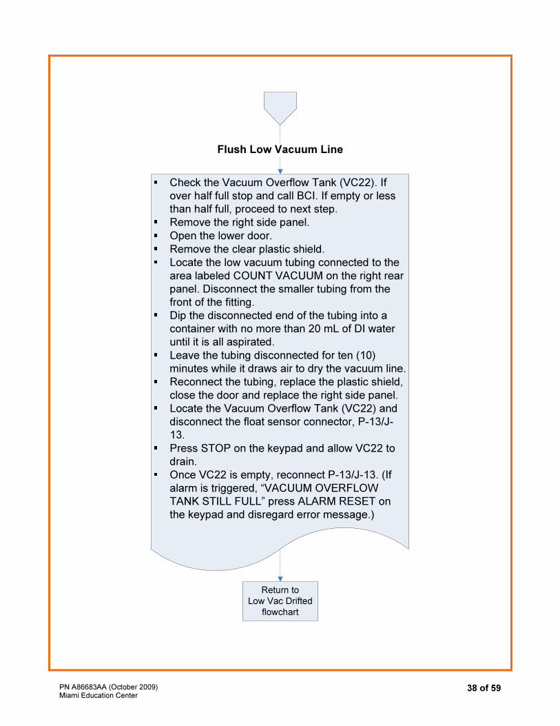
Check the Vacuum Overflow Tank (VC22). If
over half full stop and call BCI. If empty or less
than half full, proceed to next step.
Remove the right side panel.
Open the lower door.
Remove the clear plastic shield.
Locate the low vacuum tubing connected to the
area labeled COUNT VACUUM on the right rear
panel. Disconnect the smaller tubing from the
front of the fitting.
Dip the disconnected end of the tubing into a
container with no more than 20 mL of DI water
until it is all aspirated.
Leave the tubing disconnected for ten (10)
minutes while it draws air to dry the vacuum line.
Reconnect the tubing, replace the plastic shield,
close the door and replace the right side panel.
Locate the Vacuum Overflow Tank (VC22) and
disconnect the float sensor connector, P-13/J-
13.
Press STOP on the keypad and allow VC22 to
drain.
Once VC22 is empty, reconnect P-13/J-13. (If
alarm is triggered, “VACUUM OVERFLOW
TANK STILL FULL” press ALARM RESET on
the keypad and disregard error message.)
Flush Low Vacuum Line
Return to
Low Vac Drifted
flowchart
PN A86683AA (October 2009) Miami Education Center
39 of 59
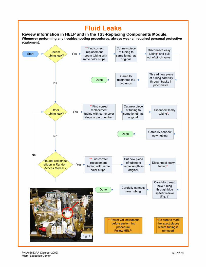
Fluid Leaks Review information in HELP and in the TS3-Replacing Components Module. Whenever performing any troubleshooting procedures, always wear all required personal protective equipment.
I-beam
tubing leak?
Round, red stripe
silicon in Random
Access Module?
Other
tubing leak?
**Find correct
replacement
I-beam tubing with
same color stripe.
Cut new piece
of tubing to
same length as
original.
Disconnect leaky
tubing* and pull
out of pinch valve.
Thread new piece
of tubing carefully
through tracks in
pinch valve.
Yes
Yes
No
**Find correct
replacement
tubing with same color
stripe or part number.
Carefully
reconnect the
two ends.
Start
Done
Cut new piece
of tubing to
same length as
original.
Disconnect leaky
tubing*.
Carefully connect
new tubingDone
No
**Find correct
replacement
tubing with same
color stripe.
Cut new piece
of tubing to
same length as
original.
Yes
No
Disconnect leaky
tubing*.
Carefully connect
new tubingDone
Carefully thread
new tubing
through blue
spacer sleeve
(Fig. 1)
**Power Off instrument
before performing
procedure.
Follow HELP.
Fig. 1
*Be sure to mark
the exact places
where tubing is
removed.
PN A86683AA (October 2009) Miami Education Center
40 of 59
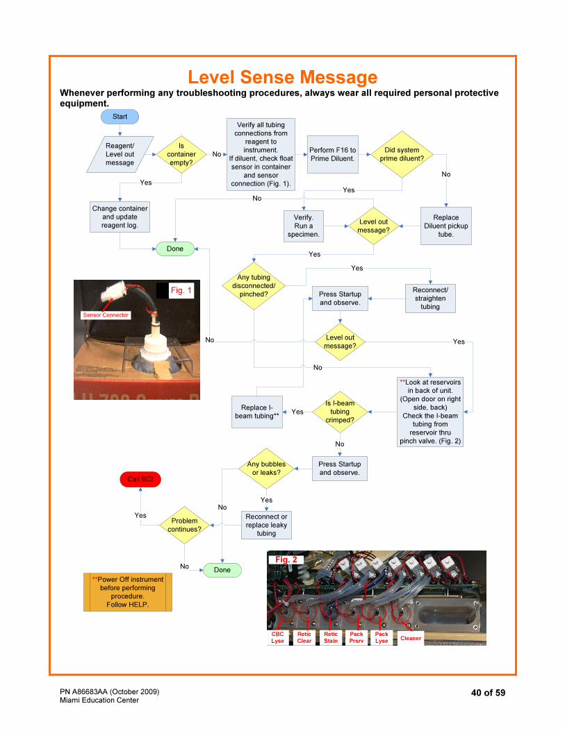
Level Sense Message Whenever performing any troubleshooting procedures, always wear all required personal protective equipment.
Start
Done
Call BCI
Is
container
empty?
Yes
Change container
and update
reagent log.
No
Verify all tubing
connections from
reagent to
instrument.
If diluent, check float
sensor in container
and sensor
connection (Fig. 1).
Any tubing
disconnected/
pinched?
No
Yes
Reconnect/
straighten
tubing
Reagent/
Level out
message
Press Startup
and observe.
Level out
message?No Yes
**Look at reservoirs
in back of unit.
(Open door on right
side, back)
Check the I-beam
tubing from
reservoir thru
pinch valve. (Fig. 2)
YesReplace I-
beam tubing**
No
Any bubbles
or leaks?
NoYes
Reconnect or
replace leaky
tubing
Problem
continues?
Yes
NoDone
**Power Off instrument
before performing
procedure.
Follow HELP.
Perform F16 to
Prime Diluent.
Did system
prime diluent?
Replace
Diluent pickup
tube.
No
Verify.
Run a
specimen.
Yes
Level out
message?
Yes
Press Startup
and observe.
No
Retic
Clear
Retic
Stain
Pack
Prsrv
Pack
Lyse Cleaner
Fig. 2
CBC
Lyse
Fig. 2
Sensor Connector
Fig. 1
Is I-beam
tubing
crimped?
PN A86683AA (October 2009) Miami Education Center
41 of 59
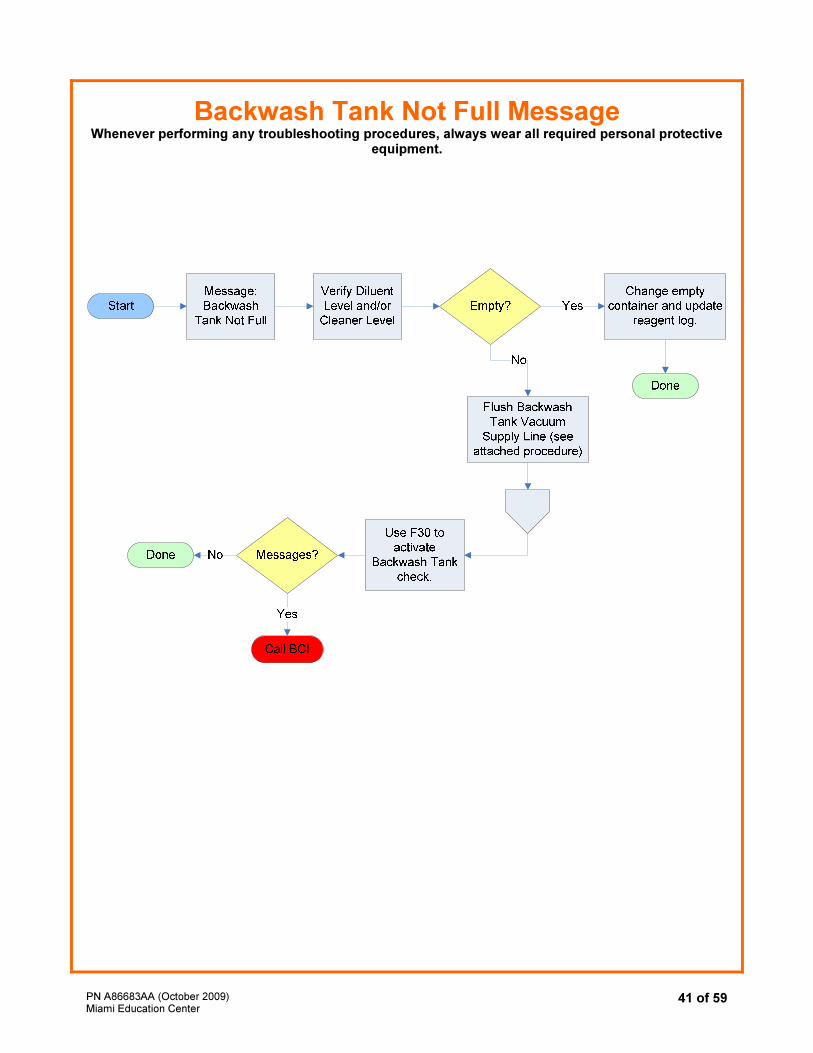
Backwash Tank Not Full Message Whenever performing any troubleshooting procedures, always wear all required personal protective
equipment.
PN A86683AA (October 2009) Miami Education Center
42 of 59
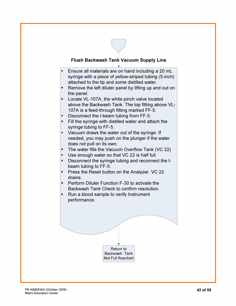
Ensure all materials are on hand including a 20 mL
syringe with a piece of yellow-striped tubing (5-inch)
attached to the tip and some distilled water.
Remove the left diluter panel by lifting up and out on
the panel.
Locate VL-107A, the white pinch valve located
above the Backwash Tank. The top fitting above VL-
107A is a feed-through fitting marked FF-5.
Disconnect the I-beam tubing from FF-5.
Fill the syringe with distilled water and attach the
syringe tubing to FF-5.
Vacuum draws the water out of the syringe. If
needed, you may push on the plunger if the water
does not pull on its own.
The water fills the Vacuum Overflow Tank (VC 22)
Use enough water so that VC 22 is half full.
Disconnect the syringe tubing and reconnect the I-
beam tubing to FF-5.
Press the Reset button on the Analyzer. VC 22
drains.
Perform Diluter Function F-30 to activate the
Backwash Tank Check to confirm resolution.
Run a blood sample to verify Instrument
performance.
Flush Backwash Tank Vacuum Supply Line
Return to
Backwash Tank
Not Full flowchart
PN A86683AA (October 2009) Miami Education Center
43 of 59
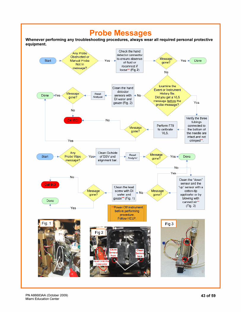
Probe Messages Whenever performing any troubleshooting procedures, always wear all required personal protective equipment.
PN A86683AA (October 2009) Miami Education Center
44 of 59
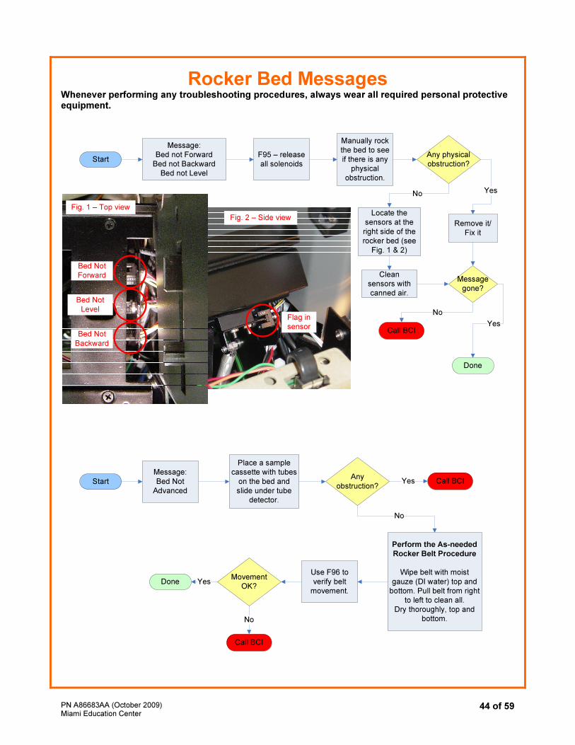
Rocker Bed Messages Whenever performing any troubleshooting procedures, always wear all required personal protective equipment.
Start
Done
Call BCI
Any physical
obstruction?
Message:
Bed not Forward
Bed not Backward
Bed not Level
F95 – release
all solenoids
Manually rock
the bed to see
if there is any
physical
obstruction.
Remove it/
Fix it
Yes
Clean
sensors with
canned air.
No
Locate the
sensors at the
right side of the
rocker bed (see
Fig. 1 & 2)
Message
gone?
Yes
No
Start
Message:
Bed Not
Advanced
Place a sample
cassette with tubes
on the bed and
slide under tube
detector.
Any
obstruction?Call BCIYes
Perform the As-needed
Rocker Belt Procedure
Wipe belt with moist
gauze (DI water) top and
bottom. Pull belt from right
to left to clean all.
Dry thoroughly, top and
bottom.
No
Use F96 to
verify belt
movement.
Movement
OK?Done
Call BCI
Yes
No
Fig. 1 – Top view
Fig. 2 – Side view
Flag in
sensorBed Not
Backward
Bed Not
Level
Bed Not
Forward
PN A86683AA (October 2009) Miami Education Center
45 of 59
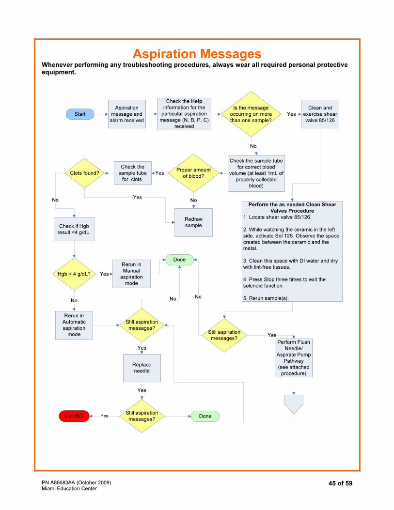
Aspiration Messages
Whenever performing any troubleshooting procedures, always wear all required personal protective equipment.
Start
Done
Call BCI
Aspiration
message and
alarm received
Check the Help
information for the
particular aspiration
message (N, B, P, C)
received
Is the message
occurring on more
than one sample?
Check the sample tube
for correct blood
volume (at least 1mL of
properly collected
blood)
No
Clean and
exercise shear
valve 85/126
Yes
Perform the as needed Clean Shear
Valves Procedure
1. Locate shear valve 85/126.
2. While watching the ceramic in the left
side, activate Sol 126. Observe the space
created between the ceramic and the
metal.
3. Clean this space with DI water and dry
with lint-free tissues.
4. Press Stop three times to exit the
solenoid function.
5. Rerun sample(s).
Check the
sample tube
for clots.
Check if Hgb
result <4 g/dL.
Proper amount
of blood?
Redraw
sample
No
YesClots found?
No
Hgb < 4 g/dL?
Rerun in
Manual
aspiration
mode
Yes
No
Rerun in
Automatic
aspiration
mode
Yes
Still aspiration
messages?Yes
NoNo
Still aspiration
messages?
YesPerform Flush
Needle/
Aspirate Pump
Pathway
(see attached
procedure)
Replace
needle
Yes
Still aspiration
messages?Yes Done
PN A86683AA (October 2009) Miami Education Center
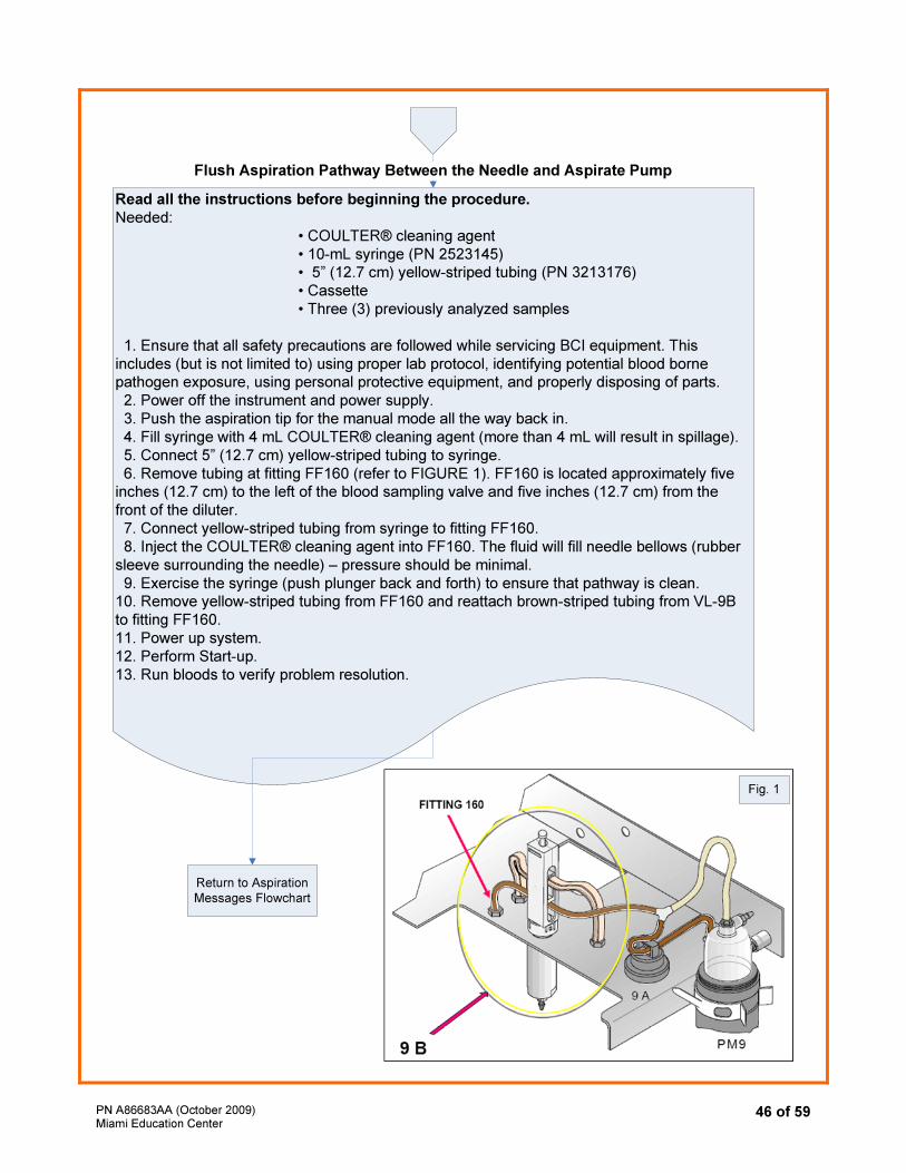
46 of 59
Read all the instructions before beginning the procedure.
Needed:
• COULTER® cleaning agent
• 10-mL syringe (PN 2523145)
• 5” (12.7 cm) yellow-striped tubing (PN 3213176)
• Cassette
• Three (3) previously analyzed samples
1. Ensure that all safety precautions are followed while servicing BCI equipment. This
includes (but is not limited to) using proper lab protocol, identifying potential blood borne
pathogen exposure, using personal protective equipment, and properly disposing of parts.
2. Power off the instrument and power supply.
3. Push the aspiration tip for the manual mode all the way back in.
4. Fill syringe with 4 mL COULTER® cleaning agent (more than 4 mL will result in spillage).
5. Connect 5” (12.7 cm) yellow-striped tubing to syringe.
6. Remove tubing at fitting FF160 (refer to FIGURE 1). FF160 is located approximately five
inches (12.7 cm) to the left of the blood sampling valve and five inches (12.7 cm) from the
front of the diluter.
7. Connect yellow-striped tubing from syringe to fitting FF160.
8. Inject the COULTER® cleaning agent into FF160. The fluid will fill needle bellows (rubber
sleeve surrounding the needle) – pressure should be minimal.
9. Exercise the syringe (push plunger back and forth) to ensure that pathway is clean.
10. Remove yellow-striped tubing from FF160 and reattach brown-striped tubing from VL-9B
to fitting FF160.
11. Power up system.
12. Perform Start-up.
13. Run bloods to verify problem resolution.
Flush Aspiration Pathway Between the Needle and Aspirate Pump
Return to Aspiration
Messages Flowchart
Fig. 1
PN A86683AA (October 2009) Miami Education Center
47 of 59
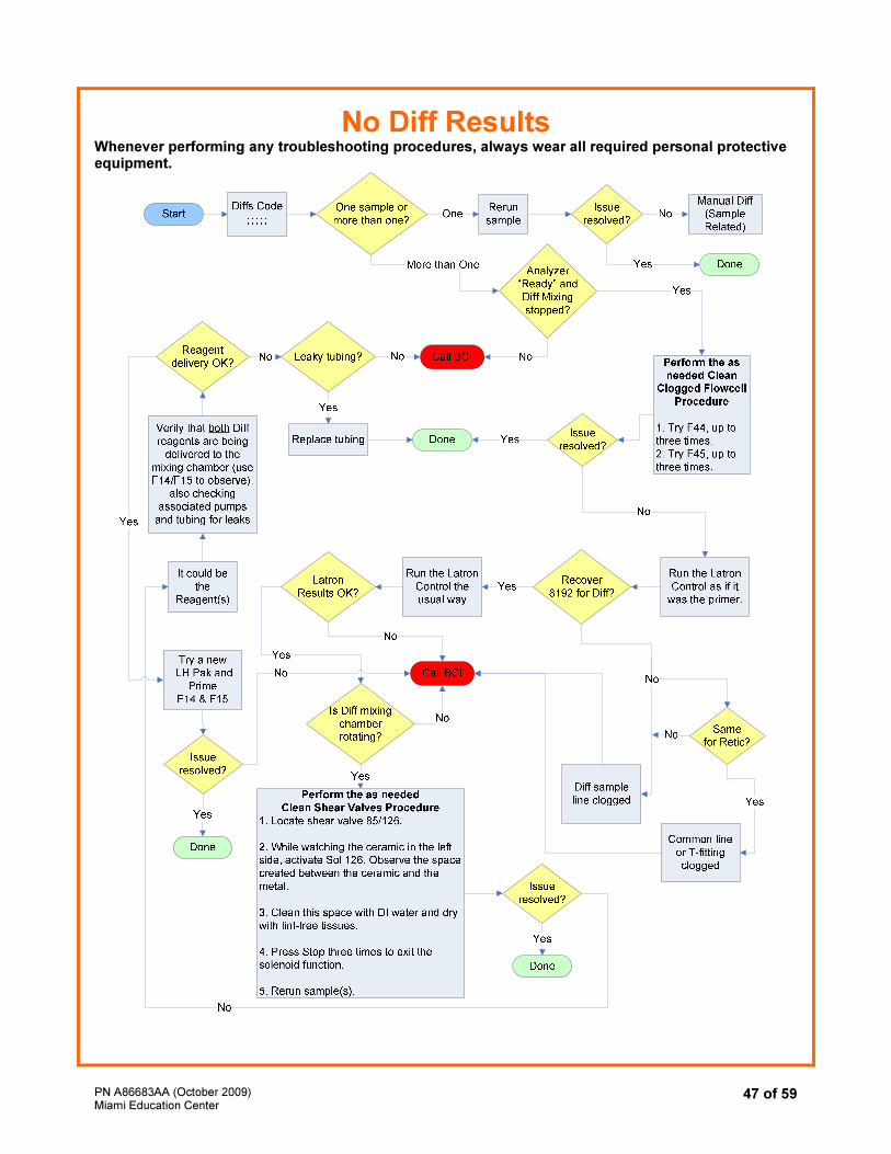
No Diff Results
Whenever performing any troubleshooting procedures, always wear all required personal protective equipment.
PN A86683AA (October 2009) Miami Education Center
48 of 59
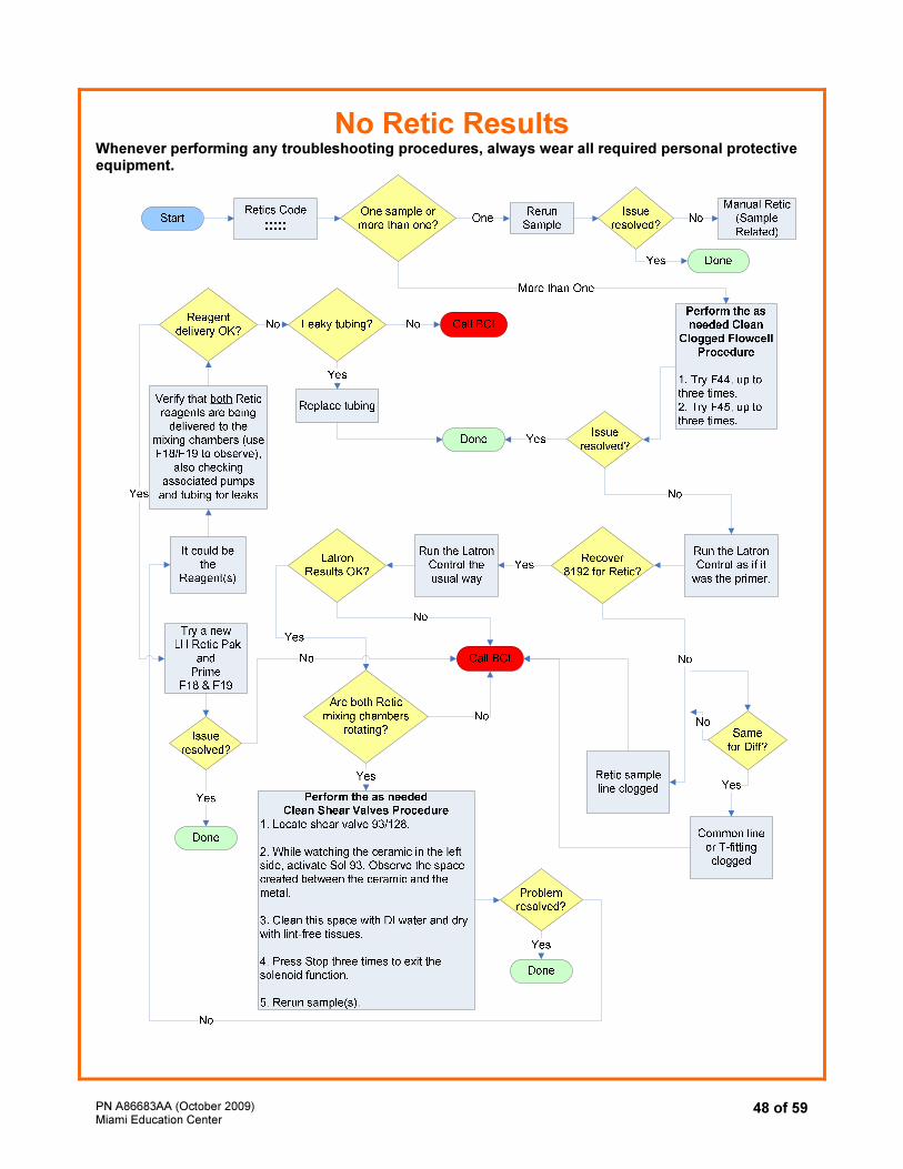
No Retic Results Whenever performing any troubleshooting procedures, always wear all required personal protective equipment.
PN A86683AA (October 2009) Miami Education Center
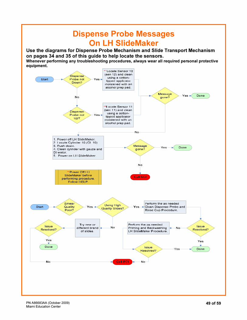
49 of 59
Dispense Probe Messages On LH SlideMaker
Use the diagrams for Dispense Probe Mechanism and Slide Transport Mechanism on pages 34 and 35 of this guide to help locate the sensors. Whenever performing any troubleshooting procedures, always wear all required personal protective equipment.
PN A86683AA (October 2009) Miami Education Center
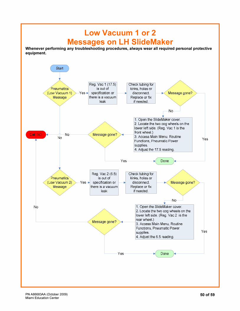
50 of 59
Low Vacuum 1 or 2 Messages on LH SlideMaker
Whenever performing any troubleshooting procedures, always wear all required personal protective equipment.
PN A86683AA (October 2009) Miami Education Center
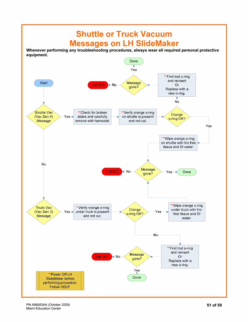
51 of 59
Shuttle or Truck Vacuum Messages on LH SlideMaker
Whenever performing any troubleshooting procedures, always wear all required personal protective equipment.
PN A86683AA (October 2009) Miami Education Center
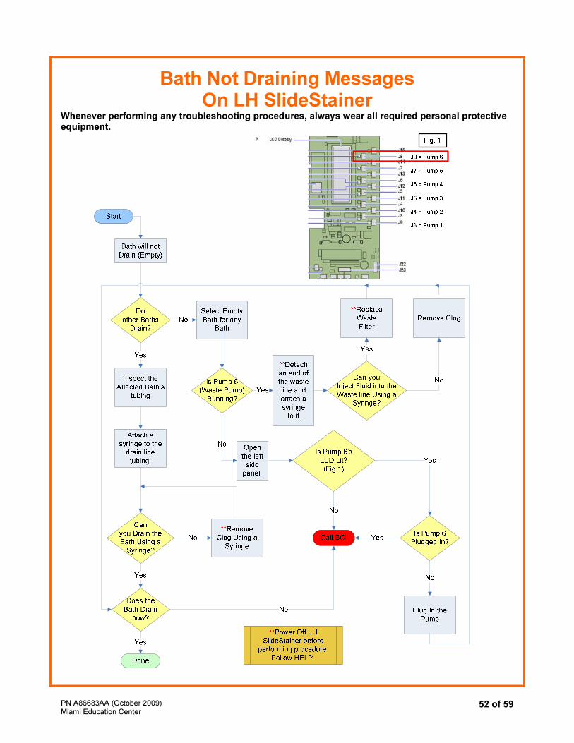
52 of 59
Bath Not Draining Messages On LH SlideStainer
Whenever performing any troubleshooting procedures, always wear all required personal protective equipment.
PN A86683AA (October 2009) Miami Education Center
53 of 59
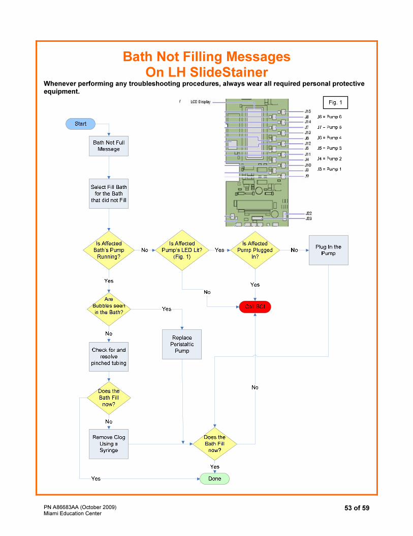
Bath Not Filling Messages On LH SlideStainer
Whenever performing any troubleshooting procedures, always wear all required personal protective equipment.
PN A86683AA (October 2009) Miami Education Center
54 of 59
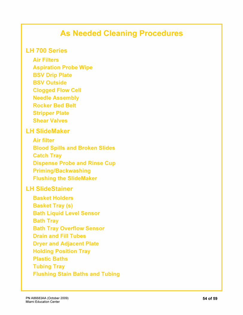
As Needed Cleaning Procedures
LH 700 Series
Air Filters
Aspiration Probe Wipe
BSV Drip Plate
BSV Outside
Clogged Flow Cell
Needle Assembly
Rocker Bed Belt
Stripper Plate
Shear Valves
LH SlideMaker
Air filter
Blood Spills and Broken Slides
Catch Tray
Dispense Probe and Rinse Cup
Priming/Backwashing
Flushing the SlideMaker
LH SlideStainer
Basket Holders
Basket Tray (s)
Bath Liquid Level Sensor
Bath Tray
Bath Tray Overflow Sensor
Drain and Fill Tubes
Dryer and Adjacent Plate
Holding Position Tray
Plastic Baths
Tubing Tray
Flushing Stain Baths and Tubing

PN A86683AA (October 2009) Miami Education Center
55 of 59
LH 700 Series
As Needed Cleaning Procedures
See Cleaning Overview in HELP to determine if certain cleaning procedures are necessary. In HELP, go to the Index tab. Type in the word Cleaning. Select overview-diluter.
Other cleaning procedures found here include the following:
COMPONENT PROCEDURE TITLE
air filter Cleaning and Replacing Air Filters
aspiration probe wipe Cleaning Manual Aspiration Probe Wipe
BSV drip plate Cleaning Blood Sampling Valve Drip Plate
BSV outside Cleaning Blood Sampling Valve (Outside Sections)
clogged flow cell Clearing Clogged Flow Cell
needle assembly Clean Needle Assembly Area
rocker bed Rocker Bed
stripper plate Stripper Plate
Shear Valve (from search tab) Cleaning the Shear Valve
PN A86683AA (October 2009) Miami Education Center
56 of 59
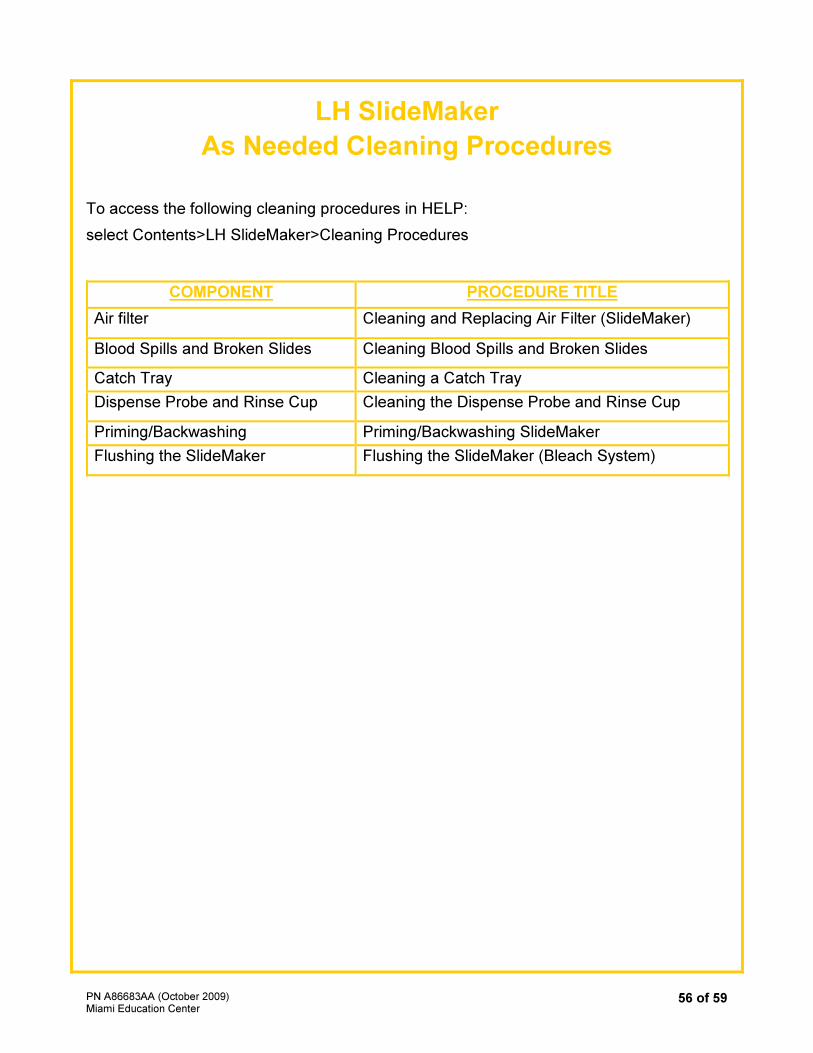
LH SlideMaker
As Needed Cleaning Procedures
To access the following cleaning procedures in HELP:
select Contents>LH SlideMaker>Cleaning Procedures
COMPONENT PROCEDURE TITLE
Air filter Cleaning and Replacing Air Filter (SlideMaker)
Blood Spills and Broken Slides Cleaning Blood Spills and Broken Slides
Catch Tray Cleaning a Catch Tray
Dispense Probe and Rinse Cup Cleaning the Dispense Probe and Rinse Cup
Priming/Backwashing Priming/Backwashing SlideMaker
Flushing the SlideMaker Flushing the SlideMaker (Bleach System)
PN A86683AA (October 2009) Miami Education Center
57 of 59
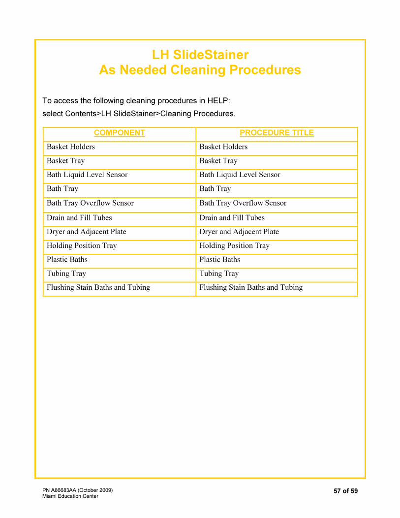
LH SlideStainer As Needed Cleaning Procedures
To access the following cleaning procedures in HELP:
select Contents>LH SlideStainer>Cleaning Procedures.
COMPONENT PROCEDURE TITLE
Basket Holders Basket Holders
Basket Tray Basket Tray
Bath Liquid Level Sensor Bath Liquid Level Sensor
Bath Tray Bath Tray
Bath Tray Overflow Sensor Bath Tray Overflow Sensor
Drain and Fill Tubes Drain and Fill Tubes
Dryer and Adjacent Plate Dryer and Adjacent Plate
Holding Position Tray Holding Position Tray
Plastic Baths Plastic Baths
Tubing Tray Tubing Tray
Flushing Stain Baths and Tubing Flushing Stain Baths and Tubing
PN
A86683A
A (
Octo
ber
2009)
Mia
mi E
ducation C
ente
r 58
of
59
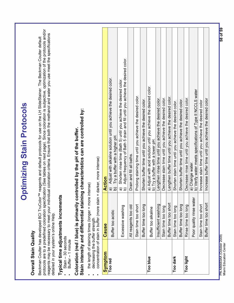
Op
tim
izin
g S
tain
Pro
toc
ols
Ove
rall
Sta
in Q
uali
ty
Beckm
an C
oulter
has d
evelo
ped
BC
I T
ruC
olo
r™ r
eage
nts
and
defa
ult p
roto
cols
fo
r use o
n t
he L
H S
lide
Sta
ine
r. T
he B
eckm
an C
oulter
defa
ult
pro
tocols
are
to
a p
redefin
ed c
olo
ration s
pecific
atio
n (
See ta
ble
s o
n n
ext p
age).
Sin
ce c
olo
ration is s
ubje
ctive,
optim
iza
tion o
f th
e p
roto
cols
and/o
r re
age
nts
ma
y b
e n
ecessary
to m
eet
your
ind
ivid
ua
l co
lora
tion c
rite
ria. E
nsure
that
both
the
meth
anol an
d w
ate
r yo
u u
se m
eet th
e s
pe
cific
atio
ns
deta
iled in y
our
sys
tem
’s o
nlin
e H
elp
.
Typ
ica
l ti
me
ad
jus
tme
nts
in
cre
me
nts
•
Sta
in –
30 s
econds
• B
uff
er
– 1
min
ute
Co
lora
tio
n (
red
/ b
lue)
is p
rim
ari
ly c
on
tro
lle
d b
y t
he
pH
of
the
bu
ffe
r.
Sta
in i
nte
ns
ity a
nd
dif
fere
nti
al
sta
inin
g c
ha
rac
teri
sti
cs c
an
are
co
ntr
olle
d b
y:
• th
e len
gth
of
sta
inin
g t
imes (
long
er
= m
ore
inte
nse)
• decre
asin
g th
e b
uff
er
str
ength
•
concentr
ation
of
sta
in in b
uff
er
(more
sta
in =
dark
er,
more
in
tense)
Sym
pto
m
Cau
se
Ac
tio
n
Buff
er
too a
cid
ic
a)
Adju
st
with a
lkalin
e s
olu
tion
until yo
u a
ch
ieve t
he d
esir
ed c
olo
r.
b)
Try
a b
uff
er
with
a h
igher
pH
.
Exce
ssiv
e w
ash
ing
a)
Short
en r
inse t
ime (
Bath
5)
until you
achie
ve th
e d
esire
d c
olo
r.
b)
Adju
st fr
equency o
f B
ath
5 d
rain
an
d f
ill u
ntil yo
u a
ch
ieve t
he d
esire
d c
olo
r.
All
rea
gents
too o
ld
Dra
in a
nd
fill
all
bath
s.
Sta
in t
ime too s
hort
P
rolo
ng s
tain
ing tim
e u
ntil you a
ch
ieve t
he d
esire
d c
olo
r.
To
o r
ed
Buff
er
tim
e too lon
g
Short
en b
uff
er
tim
e u
ntil yo
u a
chie
ve th
e d
esired c
olo
r.
Buff
er
too a
lkalin
e
a)
Adju
st
with a
cid
so
lutio
n u
ntil you
achie
ve th
e d
esire
d c
olo
r.
b)
Try
a b
uff
er
with a
lo
wer
pH
.
Insuff
icie
nt
wash
ing
Leng
the
n r
inse
tim
e u
ntil yo
u a
chie
ve th
e d
esired c
olo
r.
Sta
in t
ime too long
Decre
ase s
tain
tim
e u
ntil you a
ch
ieve t
he d
esire
d c
olo
r.
To
o b
lue
Buff
er
tim
e too s
hort
Leng
the
n b
uff
er
tim
e u
ntil you a
ch
ieve t
he d
esire
d c
olo
r.
Sta
in t
ime too long
Short
en s
tain
tim
e u
ntil you
achie
ve
the
desir
ed c
olo
r.
To
o d
ark
Buff
er
tim
e too lon
g
Short
en b
uff
er
tim
e u
ntil yo
u a
chie
ve th
e d
esired c
olo
r.
Rin
se t
ime too long
Decre
ase r
inse
tim
e u
ntil you a
ch
ieve t
he d
esire
d c
olo
r.
Poor
qua
lity r
inse w
ate
r a)
Chan
ge w
ate
r.
b)
Verify
wate
r m
eets
specific
ations o
f T
ype II
NC
CL
S w
ate
r
Sta
in t
ime too s
hort
In
cre
ase s
tain
tim
e u
ntil yo
u a
chie
ve th
e d
esired c
olo
r
To
o lig
ht
Buff
er
tim
e too s
hort
In
cre
ase b
uff
er
tim
e u
ntil you a
ch
ieve t
he d
esire
d c
olo
r
PN
A86683A
A (
Octo
ber
2009)
Mia
mi E
ducation C
ente
r 59
of
59
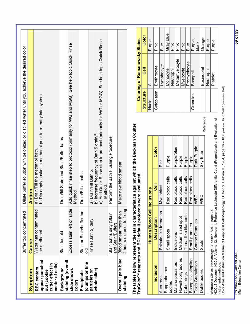
Buff
er
too c
oncentr
ate
d
Dilu
te b
uff
er
solu
tio
n w
ith d
eio
niz
ed
or
dis
tille
d w
ate
r u
ntil yo
u a
chie
ve
the
desired
colo
r
Sym
pto
m
Cau
se
Ac
tio
n
RB
C c
en
ters
a
pp
ea
r p
un
ch
ed
o
ut
(co
okie
cu
tter
eff
ect
in
cen
ter
of
cells)
Wate
r has c
onta
min
ate
d
the m
eth
ano
l a)
Dra
in/F
ill t
he m
eth
an
ol b
ath
. b)
Dip
em
pty
basket in
meth
ano
l pri
or
to r
e-e
ntr
y into
syste
m.
Sta
in t
oo o
ld
Dra
in/f
ill S
tain
and S
tain
/Bu
ffer
bath
s.
Backg
rou
nd
sta
inin
g (
ov
era
ll
slid
e s
ho
ws
co
lor)
Exce
ss s
tain
left
on
slid
e
Add q
uic
k r
inse s
tep to p
roto
col (p
rim
arily
for
WG
and M
GG
). S
ee
he
lp t
op
ic Q
uic
k R
inse
Meth
od.
Sta
in o
r S
tain
/buff
er
too
old
Dra
in/F
ill a
ll bath
s.
Rin
se (
Bath
5)
dirty
a)
Dra
in/F
ill B
ath
5.
b)
Incre
ase f
reque
ncy o
f B
ath
5 d
rain
/fill
. c)
Add Q
uic
k R
inse s
tep t
o p
roto
col (p
rim
arily
for
WG
or
MG
G).
See h
elp
top
ic Q
uic
k R
inse
Meth
od.
Pre
cip
itate
(c
lum
ps o
r fi
ne
part
icle
s o
n
wh
ole
slid
e)
Sta
in b
ath
s d
irty
(S
tain
and S
tain
/Buff
er)
P
erf
orm
the B
ath
Flu
shin
g P
rocedure
.
Ov
era
ll p
ale
blu
e
sta
inin
g
Blo
od s
mear
more
than
2 h
ours
old
prior
to f
ixin
g
Make n
ew
blo
od s
mear.
Th
e t
ab
les b
elo
w r
ep
res
en
t th
e s
tain
ch
ara
cte
risti
cs a
gain
st
wh
ich
th
e B
eck
man
Co
ult
er
Tru
Co
lor™
reag
en
ts a
nd
BC
I d
efa
ult
pro
toco
ls w
ere
ev
alu
ate
d.
R
efe
ren
ce
: Win
trobe’s
Clin
ical H
em
ato
logy, 9
th e
ditio
n, V
ol. 1
, page 2
3.
NC
CLS
Docum
ent H
20 A
, V
olu
me 1
2, N
um
ber
1. R
efe
rence L
eukocyte
Diffe
rential C
ount (P
roport
ional) a
nd E
valu
ation o
f In
str
um
enta
l m
eth
ods.
Colo
r A
tlas a
nd Instr
uction M
anual of P
eriphera
l C
ell
Morp
holo
gy, O
’Connor,
Barb
ara
H., 1
984, page 1
6 –
18.C
opie
d f
rom
: P
N 4
276448D
(N
ovem
ber
2003)
Co
lori
ng
of
Ro
man
ow
sk
y S
tain
s
Str
uctu
re
Cell
Co
lor
Nucle
i A
ll P
urp
le
Ery
thro
cyte
P
ink
Lym
phocyte
B
lue
Monocyte
G
ray b
lue
Neutr
op
hil
Pin
k
Meta
myelo
cyte
P
ink
Mye
locyte
P
ink
Cyto
pla
sm
Pro
mye
locyte
B
lue
Gra
nule
s
Basop
hil
Purp
le,
bla
ck
E
osin
op
hil
Ora
nge
N
eutr
op
hil
Purp
le
P
late
let
Purp
le
Hu
man
Blo
od
Ce
ll In
clu
sio
ns
Inclu
sio
n
Desc
rip
tio
n
Cell
Co
lor
Auer
rods
Spic
ule
-lik
e f
orm
ation
M
ye
lobla
st
Pin
k
Pap
pen
he
imer
bod
ies
Sm
all
spots
R
ed b
lood c
ells
P
urp
le
Mala
ria p
ara
sites
Inclu
sio
ns
Red b
lood c
ells
P
urp
le/b
lue
Ho
we
ll-Jolly
bo
die
s
Med
ium
siz
ed s
pot
Red b
lood c
ells
P
urp
le
Cabot
rin
gs
Thre
adlik
e f
ilam
ents
R
ed b
lood c
ells
P
urp
le
Ba
so
phili
c s
tipp
ling
Sm
all
gra
nule
s
Red b
lood c
ells
P
urp
le
Toxic
Gra
nula
tion
C
oars
e G
ranu
les
WB
C
Dark
Purp
le
Dohle
bodie
s
Spots
W
BC
S
ky-
Blu
e