Embed Size (px)
Citation preview
Eaton® LifeSense® Wireless System Quick Setup Guide
2 EATON LifeSense Wireless System Quick Setup Guide E-HOOV-II002-E August 2014
LifeSense Wireless System Quick Setup Guide
Each LifeSense kit contains:
This device complies with part 15 of the FCC Rules. Operation is subject to the following two conditions: (1) this device may not cause harmful interference, and (2) this device must accept any interference received, including interference that may cause undesired operation. The user is cautioned these devices are intentional radiators and changes or modifications not expressly approved by the party responsible for compliance will void the user’s authority to operate the equipment.
Per RSS-Gen, Section 7.1.3, This device complies with Industry Canada license-exempt RSS standard(s). Operation is subject to the following two conditions: (1) this device may not cause interference, and (2) this device must accept any interference, including interference that may cause undesired operation of the device. Suivant la section 7.1.3 du RSS-Gen, Cet appareil est conforme avec la norme RSS d'Industrie Canada exempt de licence. Son fonctionnement est soumis aux deux conditions suivantes: (1) ce dispositif ne doit pas causer d'interférences, et (2) cet appareil doit accepter toutes les interférences, y compris celles pouvant causer un mauvais fonctionnement de l'appareil.
• LifeSense hose assembly (1-100) o Sensor assembly (one per hose assembly) - FCC ID 2AABYS01; IC: 12063A-S01 o Protective sleeve (one per hose assembly)
• Wireless gateway/hose diagnostic unit (1) - FCC ID 2AABYG01; IC: 12063A-G01 o Power cord (1) o Programming cable (1–sold separately) o WIFI antenna (1) o Sensor antenna (1) o Sensor Key Fob (2)
Table of Contents
Part Listing . . . . . . . . . . . . . . . . . . . . . . . . . . . . . . . . . . . . . . . . . . . . . . . . 3 - 4
Safety Information . . . . . . . . . . . . . . . . . . . . . . . . . . . . . . . . . . . . . . . . . . . . . 5
Hose Assembly Installation . . . . . . . . . . . . . . . . . . . . . . . . . . . . . . . . . . . . . 6
Wireless Gateway (HDU) Configuration/ Configuring a New Account . . . . . . . . . . . . . . . . . . . . . . . . . . . . . . . . 7 - 12
Configuring Ethernet Connection . . . . . . . . . . . . . . . . . . . . . . . . 13 - 15
Configuring WIFI Connection . . . . . . . . . . . . . . . . . . . . . . . . . . . . 16 - 18
Associating a Sensor with the Wireless Gateway (HDU) . . . . . . . . . . 19
Sensor Status and Test . . . . . . . . . . . . . . . . . . . . . . . . . . . . . . . . . . . . . . . 19
Troubleshooting . . . . . . . . . . . . . . . . . . . . . . . . . . . . . . . . . . . . . . . . . . . . . . 20
LifeSense Setup Information Form . . . . . . . . . . . . . . . . . . . . . . . . . . 21 - 22
IMPORTANT: Before you begin the installation of your LifeSense system read through the safety instructions in this guide. For more detailed instructions on installing your system please refer to the complete LifeSense Assembly, Installation and Service Manual (E-HOOV-TI001-E2) available on Eaton's literature library (http://hydliterature.eaton.com/literature/). Hard copies of the catalog are available through Workflow One (WFO), using the Customer Connect portal, Distributor Resources, Literature. If you are unable to access the literature ordering site please contact WFO by calling 800-625-9100 or e-mailing [email protected] and WFO will walk you through the process.
3EATON LifeSense Wireless System Quick Setup Guide E-HOOV-II002-E August 2014
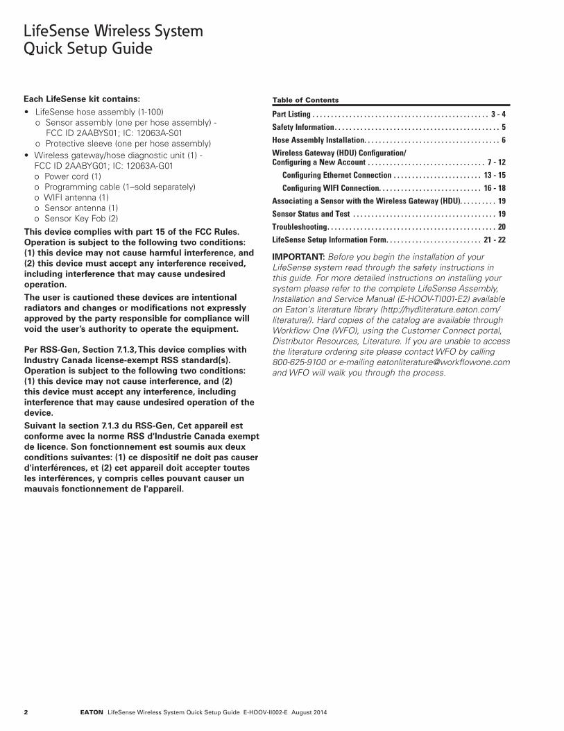
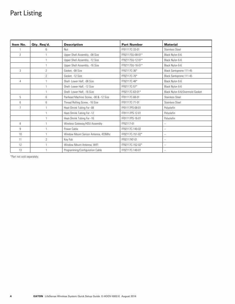
Part Listing
810
11 11
12
7
9
1
2
3
3
4
5
Sensor Type 2 (-16) Sensor Type 1 (-08 and -12)
2
4
6
GATEWAY CONNECTOR
POWER CORD
POWER CONNECTOR
SETUP CABLE
PC CONNECTOR
CABLE 1
CABLE 2
13
4 EATON LifeSense Wireless System Quick Setup Guide E-HOOV-II002-E August 2014
Item No. Qty. Req'd. Description Part Number Material
1 6 Nut FF91117C-33-01 Stainless Steel
2 1 Upper Shell Assembly, -08 Size FF92117SU-08-01* Black Nylon 6-6
1 Upper Shell Assembly, -12 Size FF92117SU-12-01* Black Nylon 6-6
1 Upper Shell Assembly, -16 Size FF92117SU-16-01* Black Nylon 6-6
3 2 Gasket, -08 Size FF92117C-36* Black Santoprene 111-45
2 Gasket, -12 Size FF92117C-70* Black Santoprene 111-45
4 1 Shell- Lower Half, -08 Size FF92117C-48* Black Nylon 6-6
1 Shell- Lower Half, -12 Size FF92117C-57* Black Nylon 6-6
1 Shell- Lower Half, -16 Size FF92117C-63-01* Black Nylon 6-6/Overmold Gasket
5 6 Panhead Machine Screw, -08 & -12 Size FF91117C-68-01 Stainless Steel
6 6 Thread Rolling Screw, -16 Size FF91117C-71-01 Stainless Steel
7 1 Heat-Shrink Tubing For -08 FF91117PS-08-01 Polyolefin
1 Heat-Shrink Tubing For -12 FF91117PS-12-01 Polyolefin
1 Heat-Shrink Tubing For -16 FF91117PS-16-01 Polyolefin
8 1 Wireless Gateway/HDU Assembly FF92117-01 --
9 1 Power Cable FF92117C-140-02 --
10 1 Window Mount Sensor Antenna, 433Mhz FF92117C-151-02* --
11 2 Key Fob FF92117KF-01 --
12 1 Window Mount Antenna, WIFI FF92117C-152-02* --
13 1 Programming/Configuration Cable FF92117C-140-01 --
*Part not sold separately.
Part Listing
5EATON LifeSense Wireless System Quick Setup Guide E-HOOV-II002-E August 2014
Safety Instructions
The Eaton LifeSense system utilizes unique hose and fittings (U.S. Patent No. 7,555,936 and 8,183,872). Only the specified LifeSense hose and fittings can be used in this system. DO NOT use other Eaton hose and hose fittings (e.g., Aeroquip, Weatherhead, or SEL), or hose and hose fittings supplied by another manufacturer with this system. Eaton hereby disclaims any obligation or liability (including incidental and consequential damages) arising from breach of contract, warranty, or tort (under negligence of strict liability theories) should other Eaton hose and hose fittings, or hose and hose fittings supplied by another manufacturer be used interchangeably with this system, or in the event that production, assembly, or installation instructions for each specified component of Eaton LifeSense are not followed.
WARNING Failure to follow process and product instructions and limitations could lead to premature hose assembly failures, resulting in property damage, serious injury or death.
WARNING Eaton LifeSense is designed to provide advance warning of impending failures due to fatigue and external abrasion. Eaton LifeSense is not designed to provide advance warning of impending failure for every failure mode. For example, failures due to improper installation of the terminal end to the application will not be alerted by LifeSense.
WARNING Verify that the specified equipment is depressurized before installing a hose assembly.
PREVENT UNAUTHORIZED OPERATION. Do not permit anyone to operate the LifeSense system unless they have been properly trained and have read and thoroughly understand this manual.
PREVENT UNAUTHORIZED SALES, ASSEMBLY, INSTALLATION AND SERVICE. Do not permit anyone to sell, assemble, install or service LifeSense hose assemblies and system unless they have been properly trained.
WARNING WEAR SAFETY GLASSES
1. Install the hose assembly into the application utilizing standard hose routing practices.
2. All wiring terminals should be properly insulated to prevent short circuits. All terminals should be of insulation grip design to provide a reliable connection and to prevent terminal fatigue.
3. Terminals that are connected where moisture may be present should be of a moisture resistant design. Molded insulators for ring terminals should be used. Molded connectors/ insulators are recommended for use with blade or pin type terminals.
4. The wireless gateway/hose diagnostic unit (HDU) shall be mounted in a location that is easily viewable by the equipment operator.
5. Never add another circuit or splice to the LifeSense power cable.
6. Never puncture power cable insulation with a probe to verify voltage.
7. Exposed ring terminals for the power supply circuit should be protected from the environment. Dielectric grease is recommended to prevent corrosion.
6 EATON LifeSense Wireless System Quick Setup Guide E-HOOV-II002-E August 2014
Hose Assembly Installation
Step 1: Depressurize Hydraulic System WARNING: Before installing any hose assembly first verify the equipment has been properly depressurized.
For depressurization instructions please refer to the equipment owner's manual for specific instructions.
Step 2: Turn Off Power Supply Be sure power supply to the equipment is turned off. For proper instructions refer to the equipment owner's manual and/or utilize a certified electrician.
Step 3: Disconnect Existing Hose Assembly Using the appropriate size wrench disconnect existing hose assembly from equipment.
Step 4: Hose Assembly LifeSense Kit(s) Purchased from Eaton: LifeSense kits supplied by Eaton include complete hose assemblies with the protective sleeve and sensor installed.
Certified LifeSense Distributors: Only certified LifeSense Distributors are authorized to make LifeSense hose assemblies. For detailed LifeSense hose assembly instructions refer to the LifeSense Assembly, Installation and Service Manual (E-HOOV-TI001-E2).
Step 5: Install LifeSense Hose Assembly with Sensor Note: Utilize standard hose routing and plumbing practices.
Starting at one end of the LifeSense hose assembly attach hose to equipment. Torque terminal end nut to the required torque specifications.
Refer to Eaton Aeroquip or Weatherhead master catalogs for proper torque specifications by terminal type and size.
Step 6: Configure Wireless Gateway (HDU) Proceed to page seven (7) of this guide for instructions on how to configure the wireless gateway (HDU) to the network on which it will communicate.
After successful configuration proceed to step seven (7) below.
Step 7: Install Wireless Gateway (HDU) Mount the wireless gateway (HDU) in a location that is easily visible to the equipment operator using adhesive Velcro strips or mounting screws.
WARNING: The wireless gateway (HDU) must be installed inside a vehicle cab or other protective area that shields it from the effects of an external environment.
Step 8: Connect Antennas to Wireless Gateway (HDU) Thread the WIFI and sensor antennas onto the respectively labeled brass antenna adapters found on the wireless gateway (HDU).
Step 9: Connect Wireless Gateway (HDU) to Power Source WARNING: The power cable must be connected to a 12- or 24-volt DC power source. Before proceeding ensure the power source is turned off. Connecting to a power source should only be performed by someone with knowledge and training in electrical systems and principles.
Connect the power cable to a 12- or 24-volt DC power source. Turn power supply back on to the equipment following the equipment owner's manual instructions.
Step 10: Wireless Gateway (HDU) Cycle Check The power light on the diagnostic unit will illuminate green when power is supplied to the unit. The unit takes approximately two (2) minutes to start up.
Step 11: Re-pressurize the hydraulic system. For system pressurizing instructions please refer to the equipment owner's manual for specific instructions.
7EATON LifeSense Wireless System Quick Setup Guide E-HOOV-II002-E August 2014
Wireless Gateway (HDU) Configuration LifeSense Installation Wizard/Configuring a New Account
Required items:
• Personalcomputerorlaptop
• Internetconnection
• Wirelessgateway/hosediagnosticunit(HDU)
• Gatewayprogrammingcable(soldseparately)– Eaton part number FF92117C-140-01
• Powercord(providedwithgateway)
• Antennas(providedwithgateway)
• LifeSensesetupinformationform(seepages21-22)
IMPORTANT: Prior to beginning the wireless gateway (HDU) configuration process be sure to have filled out the wireless LifeSense setup information form found on pages 21 and 22. Gathering the necessary information, such as the NIST and DNS IP addresses on which the gateway will be configured, will make the configuration process much easier to accomplish efficiently and successfully. Also, be sure to have the computer connected to the Internet before proceeding with the configuration process.
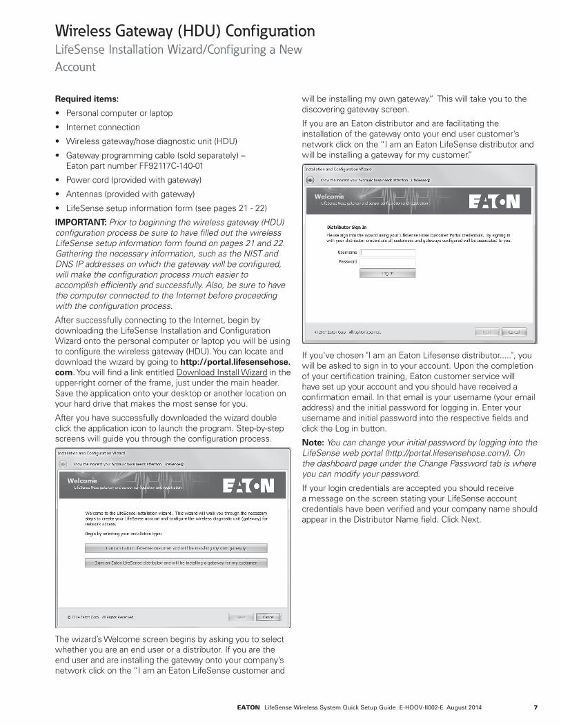
After successfully connecting to the Internet, begin by downloading the LifeSense Installation and Configuration Wizard onto the personal computer or laptop you will be using to configure the wireless gateway (HDU). You can locate and download the wizard by going to http://portal.lifesensehose.com. You will find a link entitled Download Install Wizard in the upper-right corner of the frame, just under the main header. Save the application onto your desktop or another location on your hard drive that makes the most sense for you.
After you have successfully downloaded the wizard double click the application icon to launch the program. Step-by-step screens will guide you through the configuration process.
The wizard’s Welcome screen begins by asking you to select whether you are an end user or a distributor. If you are the end user and are installing the gateway onto your company’s network click on the “I am an Eaton LifeSense customer and
will be installing my own gateway.” This will take you to the discovering gateway screen.
If you are an Eaton distributor and are facilitating the installation of the gateway onto your end user customer’s network click on the “I am an Eaton LifeSense distributor and will be installing a gateway for my customer.”
If you've chosen "I am an Eaton Lifesense distributor.....", you will be asked to sign in to your account. Upon the completion of your certification training, Eaton customer service will have set up your account and you should have received a confirmation email. In that email is your username (your email address) and the initial password for logging in. Enter your username and initial password into the respective fields and click the Log in button.
Note: You can change your initial password by logging into the LifeSense web portal (http://portal.lifesensehose.com/). On the dashboard page under the Change Password tab is where you can modify your password.
If your login credentials are accepted you should receive a message on the screen stating your LifeSense account credentials have been verified and your company name should appear in the Distributor Name field. Click Next.
8 EATON LifeSense Wireless System Quick Setup Guide E-HOOV-II002-E August 2014
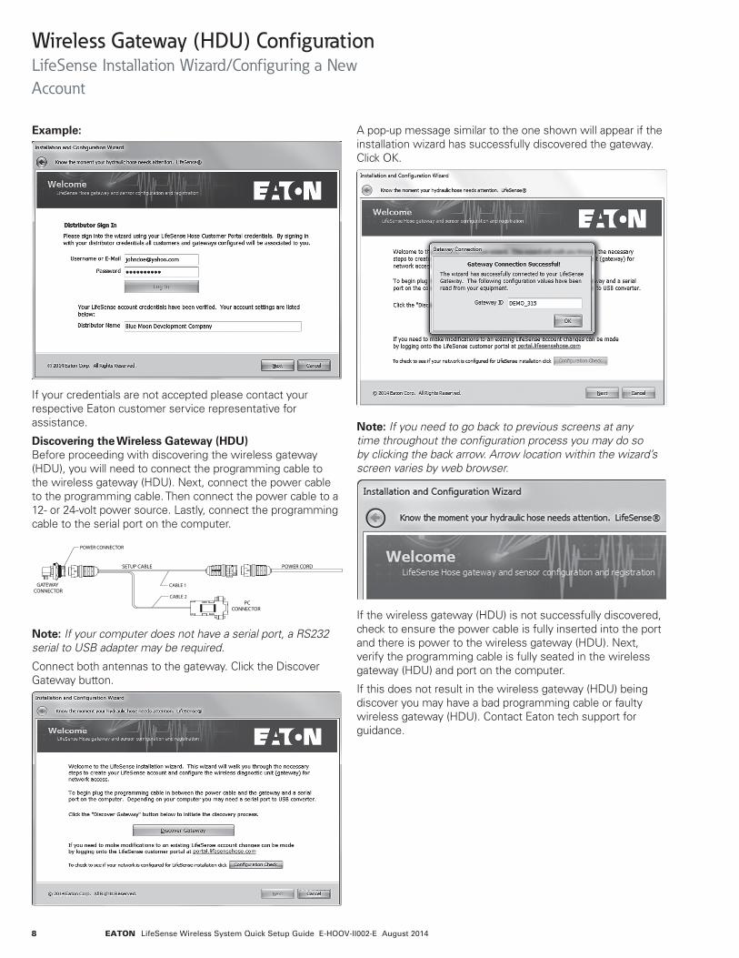
Example:
If your credentials are not accepted please contact your respective Eaton customer service representative for assistance.
Discovering the Wireless Gateway (HDU) Before proceeding with discovering the wireless gateway (HDU), you will need to connect the programming cable to the wireless gateway (HDU). Next, connect the power cable to the programming cable. Then connect the power cable to a 12- or 24-volt power source. Lastly, connect the programming cable to the serial port on the computer.
GATEWAY CONNECTOR
POWER CORD
POWER CONNECTOR
SETUP CABLE
PC CONNECTOR
CABLE 1
CABLE 2
Note: If your computer does not have a serial port, a RS232 serial to USB adapter may be required.
Connect both antennas to the gateway. Click the Discover Gateway button.
A pop-up message similar to the one shown will appear if the installation wizard has successfully discovered the gateway. Click OK.
Note: If you need to go back to previous screens at any time throughout the configuration process you may do so by clicking the back arrow. Arrow location within the wizard’s screen varies by web browser.
If the wireless gateway (HDU) is not successfully discovered, check to ensure the power cable is fully inserted into the port and there is power to the wireless gateway (HDU). Next, verify the programming cable is fully seated in the wireless gateway (HDU) and port on the computer.
If this does not result in the wireless gateway (HDU) being discover you may have a bad programming cable or faulty wireless gateway (HDU). Contact Eaton tech support for guidance.
Wireless Gateway (HDU) Configuration LifeSense Installation Wizard/Configuring a New Account

9EATON LifeSense Wireless System Quick Setup Guide E-HOOV-II002-E August 2014
Configuring a New LifeSense Account
Note: This quick setup guide assumes setting up a new LifeSense account. If you are adding to an existing account please refer to the LifeSense Assembly, Installation and Service Manual (E-HOOV-TI001-E2) for further instructions.
Select the option “I do not have a LifeSense account.”
You will need to create a username and password for the account. In the field entitled Customer Name type the name of the customer or company for which the account is being created.
When all fields have been populated, click Next.
In the Load Configuration Values portion of the wizard you will input various values needed to set up the wireless gateway (HDU) on the network on which it will operate. Click Continue with a New Configuration.
Read through the information provided on the Gateway Application Description screen which will guide you on how you should set up and identify each LifeSense system. The more detailed information that is included the easier it will be for you to quickly identify, locate, and service components within each LifeSense account in the future. After reading and comprehending the information, click Next.
Wireless Gateway (HDU) Configuration LifeSense Installation Wizard/Configuring a New Account

10 EATON LifeSense Wireless System Quick Setup Guide E-HOOV-II002-E August 2014
In the equipment information screen you will input information that will describe the piece of equipment on which the wireless gateway (HDU) will be installed. Note the wizard will automatically insert the Gateway ID number for you. Tab through the fields to input the equipment number (e.g. vehicle identification number or model number), its serial number if applicable, and a description of the equipment. After adding the requested information, click Next.
Example:
The Configure Account - Regions screen allows you to set up a region(s) for a LifeSense account. Inputting regional information will aid in quick identification of which region a piece of equipment is located. Once you’ve input the requested data, click Next.
Example:
Wireless Gateway (HDU) Configuration LifeSense Installation Wizard/Configuring a New Account
11EATON LifeSense Wireless System Quick Setup Guide E-HOOV-II002-E August 2014
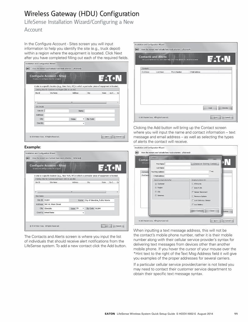
In the Configure Account - Sites screen you will input information to help you identify the site (e.g., truck depot) within a region where the equipment is located. Click Next after you have completed filling out each of the required fields.
Example:
The Contacts and Alerts screen is where you input the list of individuals that should receive alert notifications from the LifeSense system. To add a new contact click the Add button.
Clicking the Add button will bring up the Contact screen where you will input the name and contact information – text message and email address – as well as selecting the types of alerts the contact will receive.
When inputting a text message address, this will not be the contact’s mobile phone number, rather it is their mobile number along with their cellular service provider’s syntax for delivering text messages from devices other than another mobile phone. If you hover the cursor of your mouse over the *Hint text to the right of the Text Msg Address field it will give you examples of the proper addresses for several carriers.
If a particular cellular service provider/carrier is not listed you may need to contact their customer service department to obtain their specific text message syntax.
Wireless Gateway (HDU) Configuration LifeSense Installation Wizard/Configuring a New Account
12 EATON LifeSense Wireless System Quick Setup Guide E-HOOV-II002-E August 2014
Example:
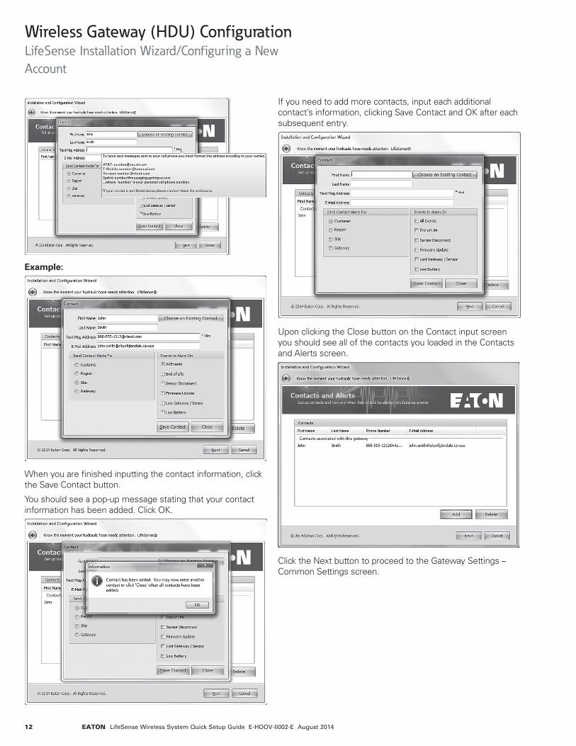
When you are finished inputting the contact information, click the Save Contact button.
You should see a pop-up message stating that your contact information has been added. Click OK.
If you need to add more contacts, input each additional contact’s information, clicking Save Contact and OK after each subsequent entry.
Upon clicking the Close button on the Contact input screen you should see all of the contacts you loaded in the Contacts and Alerts screen.
Click the Next button to proceed to the Gateway Settings – Common Settings screen.
Wireless Gateway (HDU) Configuration LifeSense Installation Wizard/Configuring a New Account
13EATON LifeSense Wireless System Quick Setup Guide E-HOOV-II002-E August 2014
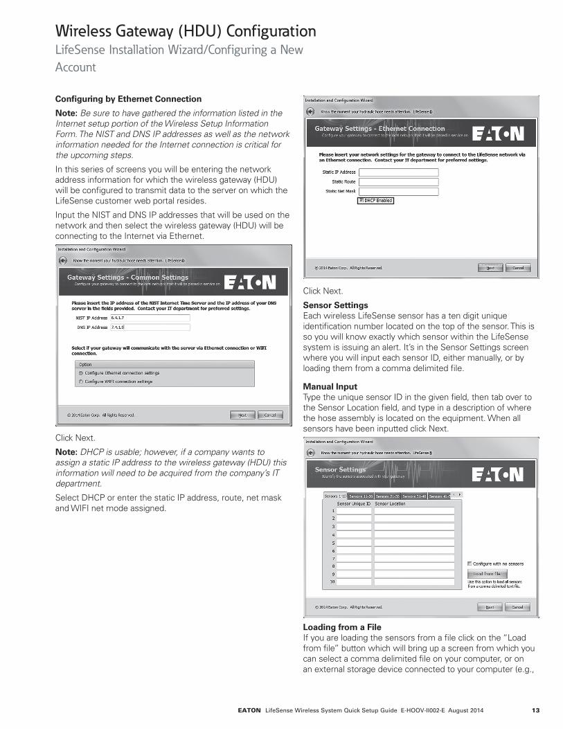
Configuring by Ethernet Connection
Note: Be sure to have gathered the information listed in the Internet setup portion of the Wireless Setup Information Form. The NIST and DNS IP addresses as well as the network information needed for the Internet connection is critical for the upcoming steps.
In this series of screens you will be entering the network address information for which the wireless gateway (HDU) will be configured to transmit data to the server on which the LifeSense customer web portal resides.
Input the NIST and DNS IP addresses that will be used on the network and then select the wireless gateway (HDU) will be connecting to the Internet via Ethernet.
Click Next.
Note: DHCP is usable; however, if a company wants to assign a static IP address to the wireless gateway (HDU) this information will need to be acquired from the company’s IT department.
Select DHCP or enter the static IP address, route, net mask and WIFI net mode assigned.
Click Next.
Sensor Settings Each wireless LifeSense sensor has a ten digit unique identification number located on the top of the sensor. This is so you will know exactly which sensor within the LifeSense system is issuing an alert. It’s in the Sensor Settings screen where you will input each sensor ID, either manually, or by loading them from a comma delimited file.
Manual Input Type the unique sensor ID in the given field, then tab over to the Sensor Location field, and type in a description of where the hose assembly is located on the equipment. When all sensors have been inputted click Next.
Loading from a File If you are loading the sensors from a file click on the “Load from file” button which will bring up a screen from which you can select a comma delimited file on your computer, or on an external storage device connected to your computer (e.g.,
Wireless Gateway (HDU) Configuration LifeSense Installation Wizard/Configuring a New Account
14 EATON LifeSense Wireless System Quick Setup Guide E-HOOV-II002-E August 2014
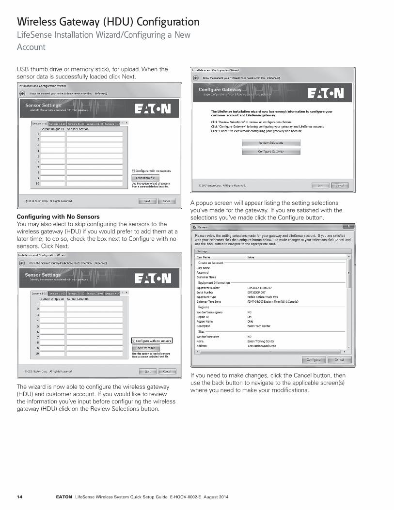
USB thumb drive or memory stick), for upload. When the sensor data is successfully loaded click Next.
Configuring with No Sensors You may also elect to skip configuring the sensors to the wireless gateway (HDU) if you would prefer to add them at a later time; to do so, check the box next to Configure with no sensors. Click Next.
The wizard is now able to configure the wireless gateway (HDU) and customer account. If you would like to review the information you’ve input before configuring the wireless gateway (HDU) click on the Review Selections button.
A popup screen will appear listing the setting selections you’ve made for the gateway. If you are satisfied with the selections you’ve made click the Configure button.
If you need to make changes, click the Cancel button, then use the back button to navigate to the applicable screen(s) where you need to make your modifications.
Wireless Gateway (HDU) Configuration LifeSense Installation Wizard/Configuring a New Account

15EATON LifeSense Wireless System Quick Setup Guide E-HOOV-II002-E August 2014
When you are completely satisfied with your selections click on the Configure Gateway button.
If your configuration is successful you will receive the following message screen. If you would like to save a file of your account configuration click on the Save Wizard Configuration button, doing so will bring up a Windows Explorer screen where you can chose to save the .ini file on your computer or external storage device.
Click Finish to exit the LifeSense installation wizard application.
To verify the gateway you have just configured is successfully communicating to the Eaton server open your Internet browser and navigate to the LifeSense web portal by typing the following address (http://portal.lifesensehose.com) into the address or URL field.
This will take you to the main login page of the LifeSense web portal. Login using your username (your email address) and password.
If the wireless gateway (HDU) is communicating properly to the server you should see the wireless gateway (HDU) identification number and all of the sensors that are associated with that wireless gateway (HDU) appearing in the Alert and Sensor Status screens.
Wireless Gateway (HDU) Configuration LifeSense Installation Wizard/Configuring a New Account
16 EATON LifeSense Wireless System Quick Setup Guide E-HOOV-II002-E August 2014
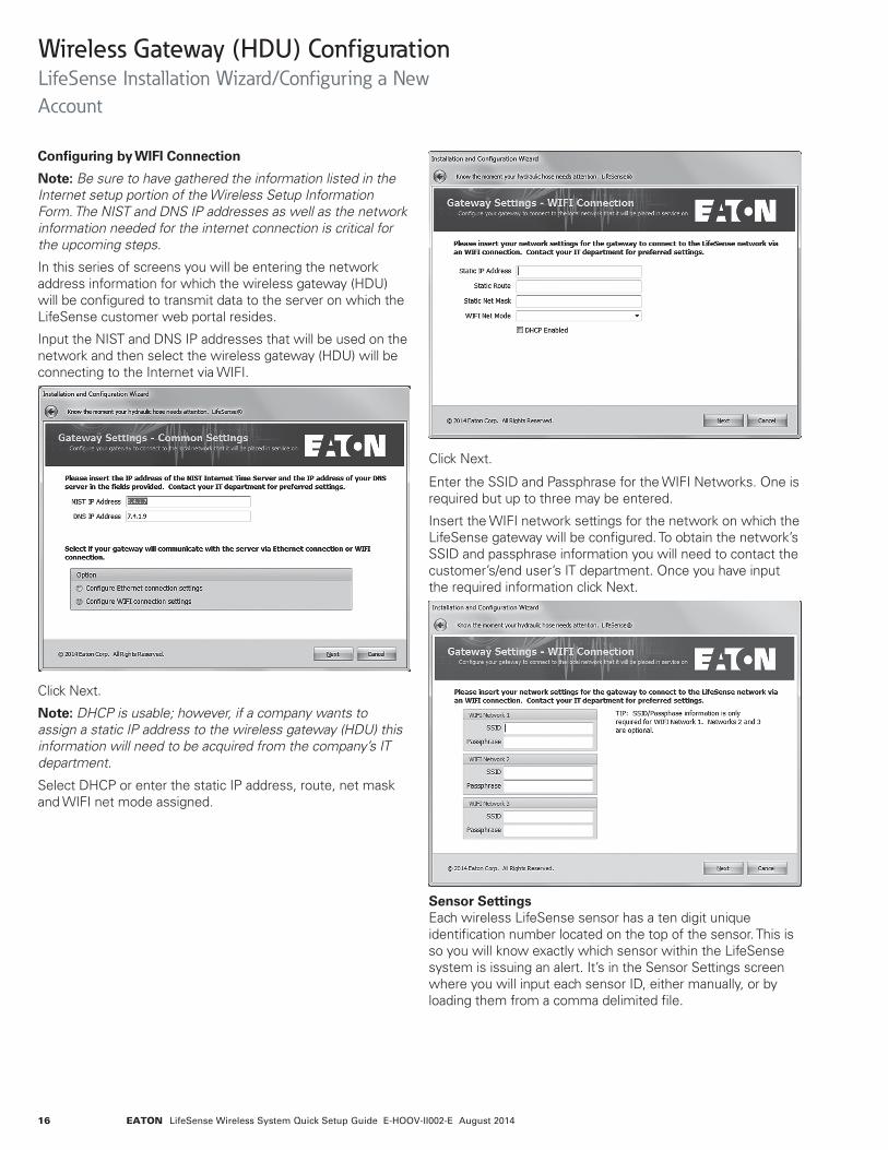
Configuring by WIFI Connection
Note: Be sure to have gathered the information listed in the Internet setup portion of the Wireless Setup Information Form. The NIST and DNS IP addresses as well as the network information needed for the internet connection is critical for the upcoming steps.
In this series of screens you will be entering the network address information for which the wireless gateway (HDU) will be configured to transmit data to the server on which the LifeSense customer web portal resides.
Input the NIST and DNS IP addresses that will be used on the network and then select the wireless gateway (HDU) will be connecting to the Internet via WIFI.
Click Next.
Note: DHCP is usable; however, if a company wants to assign a static IP address to the wireless gateway (HDU) this information will need to be acquired from the company’s IT department.
Click Next.
Enter the SSID and Passphrase for the WIFI Networks. One is required but up to three may be entered.
Insert the WIFI network settings for the network on which the LifeSense gateway will be configured. To obtain the network’s SSID and passphrase information you will need to contact the customer’s/end user’s IT department. Once you have input the required information click Next.
Sensor Settings Each wireless LifeSense sensor has a ten digit unique identification number located on the top of the sensor. This is so you will know exactly which sensor within the LifeSense system is issuing an alert. It’s in the Sensor Settings screen where you will input each sensor ID, either manually, or by loading them from a comma delimited file.
Select DHCP or enter the static IP address, route, net mask and WIFI net mode assigned.
Wireless Gateway (HDU) Configuration LifeSense Installation Wizard/Configuring a New Account

17EATON LifeSense Wireless System Quick Setup Guide E-HOOV-II002-E August 2014
Manual Input Type in the unique sensor ID in the given field and then tab over to the Sensor Location field and type in a description of where the hose assembly with sensor is located on the equipment. When all sensors in the system have been inputted click Next.
Loading from a File If you are loading the sensors from a comma delimited file click on the “Load from file” button which will bring up a screen from which you can select a comma delimited file on your computer, or on an external storage device connected to your computer (e.g., USB thumb drive or memory stick), for upload. When the sensor data is successfully loaded click Next.
Configuring with No Sensors You may also elect to skip configuring the sensors to the gateway if you would prefer to add them at a later time; to do so, check the box next to Configure with no sensors. Click Next.
The wizard is now able to configure the gateway and customer account. If you would like to review the information you’ve input before configuring the gateway click on the Review Selections button.
Wireless Gateway (HDU) Configuration LifeSense Installation Wizard/Configuring a New Account
18 EATON LifeSense Wireless System Quick Setup Guide E-HOOV-II002-E August 2014
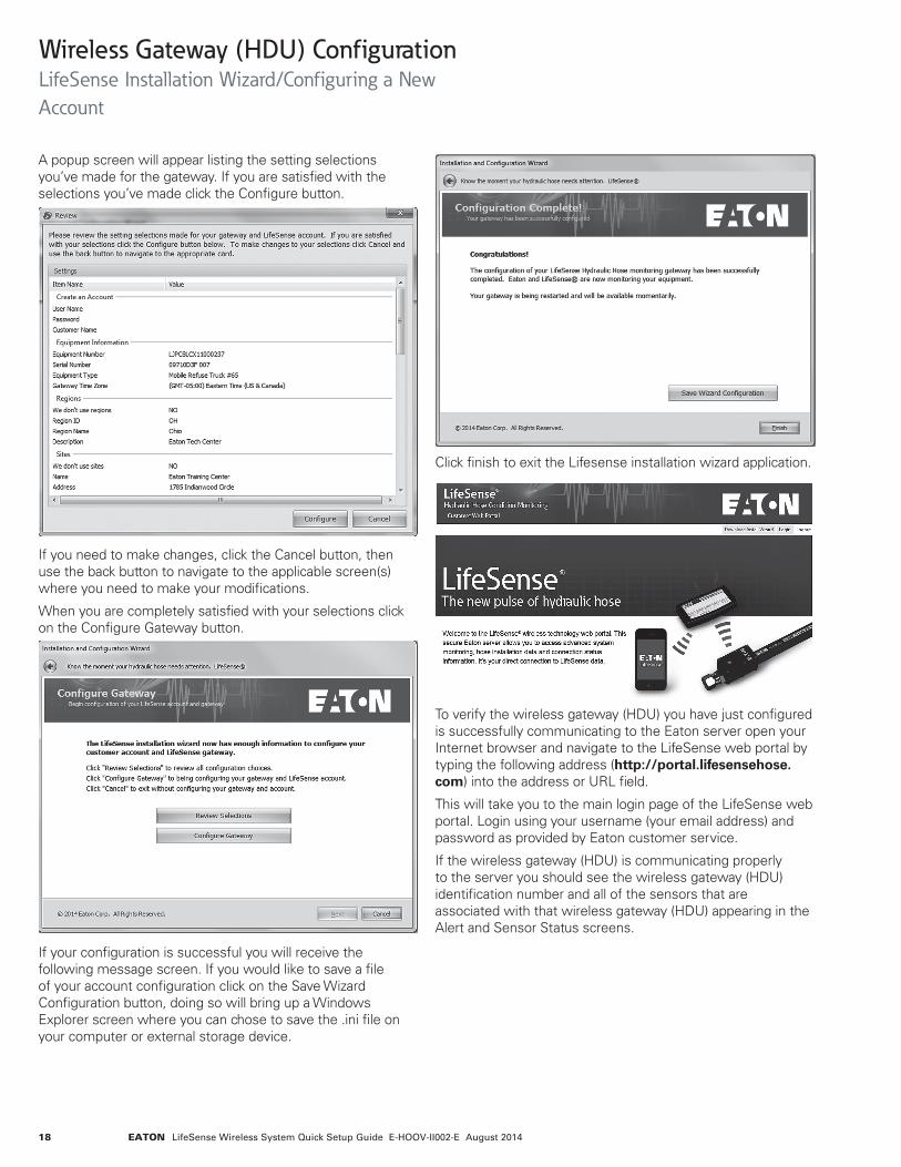
A popup screen will appear listing the setting selections you’ve made for the gateway. If you are satisfied with the selections you’ve made click the Configure button.
If you need to make changes, click the Cancel button, then use the back button to navigate to the applicable screen(s) where you need to make your modifications.
When you are completely satisfied with your selections click on the Configure Gateway button.
If your configuration is successful you will receive the following message screen. If you would like to save a file of your account configuration click on the Save Wizard Configuration button, doing so will bring up a Windows Explorer screen where you can chose to save the .ini file on your computer or external storage device.
To verify the wireless gateway (HDU) you have just configured is successfully communicating to the Eaton server open your Internet browser and navigate to the LifeSense web portal by typing the following address (http://portal.lifesensehose.com) into the address or URL field.
This will take you to the main login page of the LifeSense web portal. Login using your username (your email address) and password as provided by Eaton customer service.
If the wireless gateway (HDU) is communicating properly to the server you should see the wireless gateway (HDU) identification number and all of the sensors that are associated with that wireless gateway (HDU) appearing in the Alert and Sensor Status screens.
Click finish to exit the Lifesense installation wizard application.
Wireless Gateway (HDU) Configuration LifeSense Installation Wizard/Configuring a New Account
19EATON LifeSense Wireless System Quick Setup Guide E-HOOV-II002-E August 2014
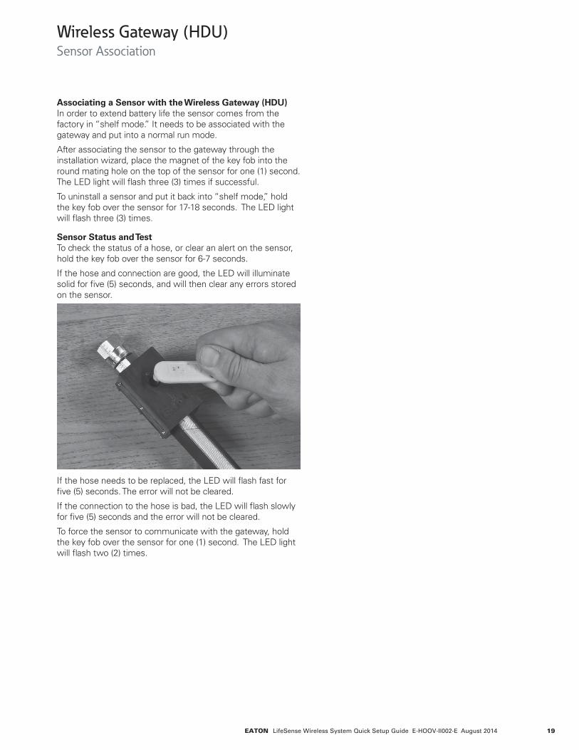
Associating a Sensor with the Wireless Gateway (HDU) In order to extend battery life the sensor comes from the factory in “shelf mode.” It needs to be associated with the gateway and put into a normal run mode.
After associating the sensor to the gateway through the installation wizard, place the magnet of the key fob into the round mating hole on the top of the sensor for one (1) second. The LED light will flash three (3) times if successful.
To uninstall a sensor and put it back into “shelf mode,” hold the key fob over the sensor for 17-18 seconds. The LED light will flash three (3) times.
Sensor Status and Test To check the status of a hose, or clear an alert on the sensor, hold the key fob over the sensor for 6-7 seconds.
If the hose and connection are good, the LED will illuminate solid for five (5) seconds, and will then clear any errors stored on the sensor.
If the hose needs to be replaced, the LED will flash fast for five (5) seconds. The error will not be cleared.
If the connection to the hose is bad, the LED will flash slowly for five (5) seconds and the error will not be cleared.
To force the sensor to communicate with the gateway, hold the key fob over the sensor for one (1) second. The LED light will flash two (2) times.
Wireless Gateway (HDU) Sensor Association
20 EATON LifeSense Wireless System Quick Setup Guide E-HOOV-II002-E August 2014
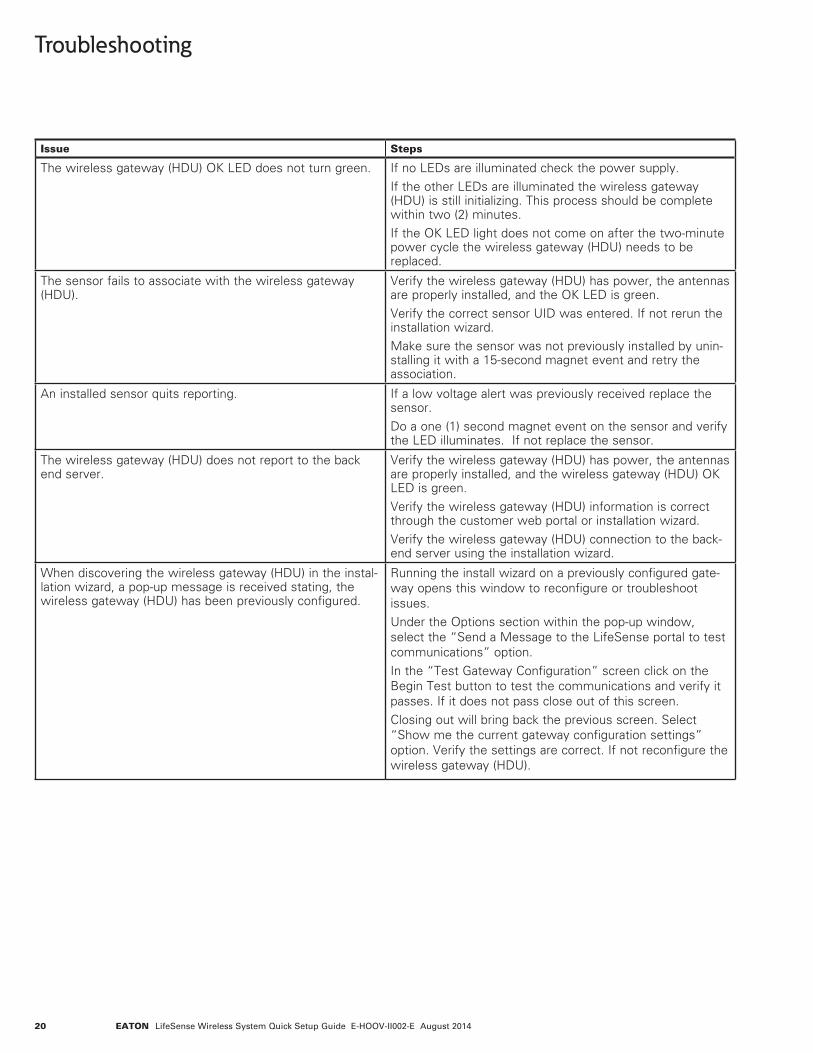
Troubleshooting
Issue Steps
The wireless gateway (HDU) OK LED does not turn green. If no LEDs are illuminated check the power supply. If the other LEDs are illuminated the wireless gateway (HDU) is still initializing. This process should be complete within two (2) minutes. If the OK LED light does not come on after the two-minute power cycle the wireless gateway (HDU) needs to be replaced.
The sensor fails to associate with the wireless gateway (HDU).
Verify the wireless gateway (HDU) has power, the antennas are properly installed, and the OK LED is green. Verify the correct sensor UID was entered. If not rerun the installation wizard. Make sure the sensor was not previously installed by unin-stalling it with a 15-second magnet event and retry the association.
An installed sensor quits reporting. If a low voltage alert was previously received replace the sensor. Do a one (1) second magnet event on the sensor and verify the LED illuminates. If not replace the sensor.
The wireless gateway (HDU) does not report to the back end server.
Verify the wireless gateway (HDU) has power, the antennas are properly installed, and the wireless gateway (HDU) OK LED is green. Verify the wireless gateway (HDU) information is correct through the customer web portal or installation wizard. Verify the wireless gateway (HDU) connection to the back-end server using the installation wizard.
When discovering the wireless gateway (HDU) in the instal-lation wizard, a pop-up message is received stating, the wireless gateway (HDU) has been previously configured.
Running the install wizard on a previously configured gate-way opens this window to reconfigure or troubleshoot issues. Under the Options section within the pop-up window, select the “Send a Message to the LifeSense portal to test communications” option. In the “Test Gateway Configuration” screen click on the Begin Test button to test the communications and verify it passes. If it does not pass close out of this screen. Closing out will bring back the previous screen. Select “Show me the current gateway configuration settings” option. Verify the settings are correct. If not reconfigure the wireless gateway (HDU).
21EATON LifeSense Wireless System Quick Setup Guide E-HOOV-II002-E August 2014
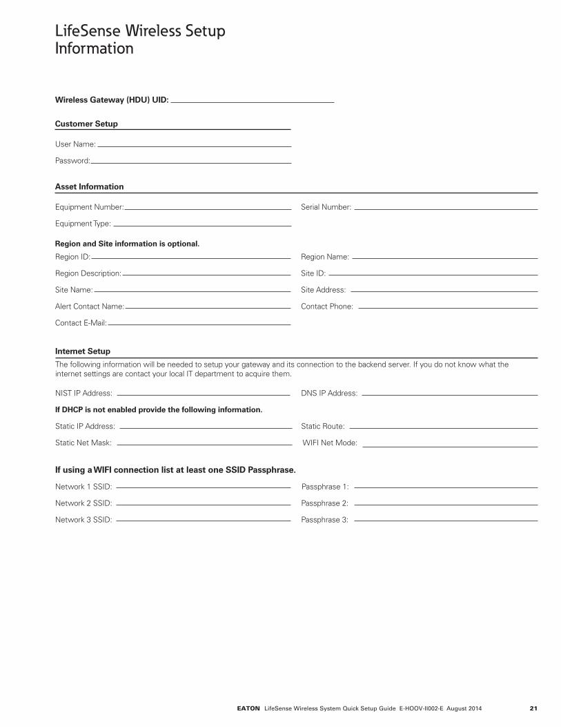
LifeSense Wireless Setup Information
Wireless Gateway (HDU) UID:
Customer Setup
User Name:
Password:
Asset Information
Equipment Number: Serial Number:
Equipment Type:
Region and Site information is optional.
Region ID: Region Name:
Region Description: Site ID:
Site Name: Site Address:
Alert Contact Name: Contact Phone:
Contact E-Mail:
Internet Setup
The following information will be needed to setup your gateway and its connection to the backend server. If you do not know what the internet settings are contact your local IT department to acquire them.
NIST IP Address: DNS IP Address:
If DHCP is not enabled provide the following information.
Static IP Address: Static Route:
Static Net Mask: WIFI Net Mode:
If using a WIFI connection list at least one SSID Passphrase.
Network 1 SSID: Passphrase 1:
Network 2 SSID: Passphrase 2:
Network 3 SSID: Passphrase 3:
22 EATON LifeSense Wireless System Quick Setup Guide E-HOOV-II002-E August 2014
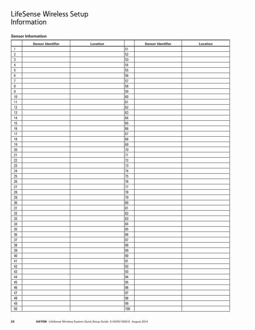
LifeSense Wireless Setup Information
Sensor Information
Sensor Identifier Location Sensor Identifier Location
1 512 523 534 545 556 567 578 589 5910 6011 6112 6213 6314 6415 6516 6617 6718 6819 6920 7021 7122 7223 7324 7425 7526 7627 7728 7829 7930 8031 8132 8233 8334 8435 8536 8637 8738 8839 8940 9041 9142 9243 9344 9445 9546 9647 9748 9849 9950 100
EatonHydraulics Group USA14615 Lone Oak RoadEden Prairie, MN 55344USATel: 952-937-9800Fax: 952-294-7722
EatonHydraulics Group EuropeRoute de la Longeraie 71110 MorgesSwitzerlandTel: +41 (0) 21 811 4600Fax: +41 (0) 21 811 4601
EatonHydraulics Group Asia PacificEaton BuildingNo.7 Lane 280 Linhong RoadChangning District,Shanghai 200335ChinaTel: (+86 21) 5200 0099Fax: (+86 21) 2230 7240
© 2014 Eaton All Rights Reserved Printed in USADocument No. E-HOOV-II002-EAugust 2014