Embed Size (px)
Citation preview
Medium-voltage vacuum circuit breakersCatalog information
Eaton’s Cooper Power Systems catalogMedium-voltage vacuum circuit breakers
Contents
Description Page
Type VSA20B air-insulated; vacuum; electronically controlled power circuit breaker (290-25) . . . . . . . . . . . . . . . . . . . . . . . . . . . . . . . . . . . . . . . . . 3
Medium-voltage vacuum circuit breakers catalog contents
Technical Data Effective August 2014
Medium-voltage vacuum circuit breakers catalog
www.cooperpower.com
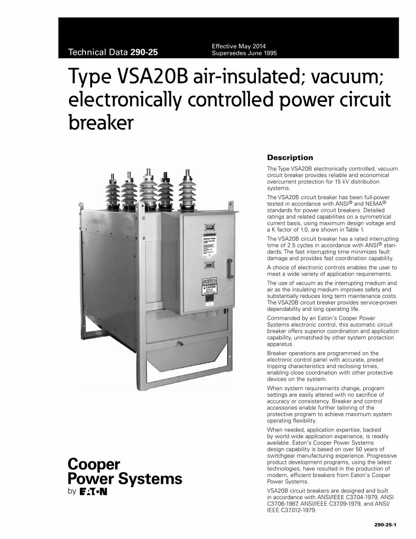
DescriptionThe Type VSA20B electronically controlled, vacuum circuit breaker provides reliable and economical overcurrent protection for 15 kV distribution systems.
The VSA20B circuit breaker has been full-power tested in accordance with ANSI® and NEMA® standards for power circuit breakers. Detailed ratings and related capabilities on a symmetrical current basis, using maximum design voltage and a K factor of 1.0, are shown in Table 1.
The VSA20B circuit breaker has a rated interrupting time of 2.5 cycles in accordance with ANSI® stan-dards. The fast interrupting time minimizes fault damage and provides fast coordination capability.
A choice of electronic controls enables the user to meet a wide variety of application requirements.
The use of vacuum as the interrupting medium and air as the insulating medium improves safety and substantially reduces long term maintenance costs. The VSA20B circuit breaker provides service-proven dependability and long operating life.
Commanded by an Eaton's Cooper Power Systems electronic control, this automatic circuit breaker offers superior coordination and application capability, unmatched by other system protection apparatus.
Breaker operations are programmed on the electronic control panel with accurate, preset tripping characteristics and reclosing times, enabling close coordination with other protective devices on the system.
When system requirements change, program settings are easily altered with no sacrifice of accuracy or consistency. Breaker and control accessories enable further tailoring of the protective program to achieve maximum system operating flexibility.
When needed, application expertise, backed by world wide application experience, is readily available. Eaton's Cooper Power Systems design capability is based on over 50 years of switchgear manufacturing experience. Progressive product development programs, using the latest technologies, have resulted in the production of modern, efficient breakers from Eaton's Cooper Power Systems.
VSA20B circuit breakers are designed and built in accordance with ANSI/IEEE C37.04-1979, ANSI C37.06-1987, ANSI/IEEE C37.09-1979, and ANSI/IEEE C37.012-1979.
Type VSA20B air-insulated; vacuum; electronically controlled power circuit breaker
290-25-1
Technical Data 290-25Effective May 2014Supersedes June 1995
RatingsThe Type VSA20B circuit breaker can be applied on distributions systems ranging from 2.4 through 14.4 kV. Standard duty cycle is; CO-15 seconds-CO. Basic ratings are shown in Table 1.
Characteristic featuresFault-sensing information for VSA20B circuit breakers is supplied to the electronic control by bushing-type current transformers mounted in the circuit breaker. Tripping and closing signals from the control energize operating circuits in the circuit breaker.
Minimum-trip values of the control are independent of the continuous current and interrupting ratings of the circuit breaker. Flexibility in coordination with other protective devices is provided by dual time-current characteristics available from a broad choice of time-current curves, a wide range of minimum-trip values, and a variety of programmable reclosing times.
Energy to operate the vacuum interrupters is provided by a motor-driven operator supplied from a 240 Vac source. The motor operator closes the circuit breaker by charging the closing springs, which in turn provides the force to close the vacuum interrupters and charge the opening springs.
Eaton's Cooper Power Systems vacuum interrupters have had an excellent field reliability record since their initial introduction in 1966 in the most complete line of vacuum switchgear available in the industry.
Mounting equipmentVSA20B circuit breakers are furnished in standard frames with corner lifting eyes. Mounting equipment is available for substation installation of the circuit breaker (see Table 6 for mounting accessories).
Surge protection Best operating results are achieved when circuit breakers are protected with surge arresters. In substations, arresters should be located on the load side.
Eaton's Cooper Power Systems distribution-class surge arresters provide excellent protection. See Catalog Section 235-35, UltraSIL™ Polymer-Housed VariSTAR™ Surge Arresters and 235-99, UltraSIL Polymer-Housed Evolution™ Surge Arresters.
Ordering informationA complete electronically controlled VSA20B circuit breaker installation includes:• Circuit breaker and its accessories• Electronic control and its accessories• Control cable• Mounting equipment
The circuit breaker, control, and interconnecting cable are ordered and priced separately. Accessories for the circuit breaker and the control are ordered and priced separately.
To order a circuit breaker, electronic control, and control cable:
1. Use Table 2 to specify the catalog number for the circuit breaker.
2. From Tables 3 - 6, specify the catalog numbers that describe the required circuit breaker accessories and mounting equipment.
3. Order the required electronic control (control is priced separately from circuit breaker).
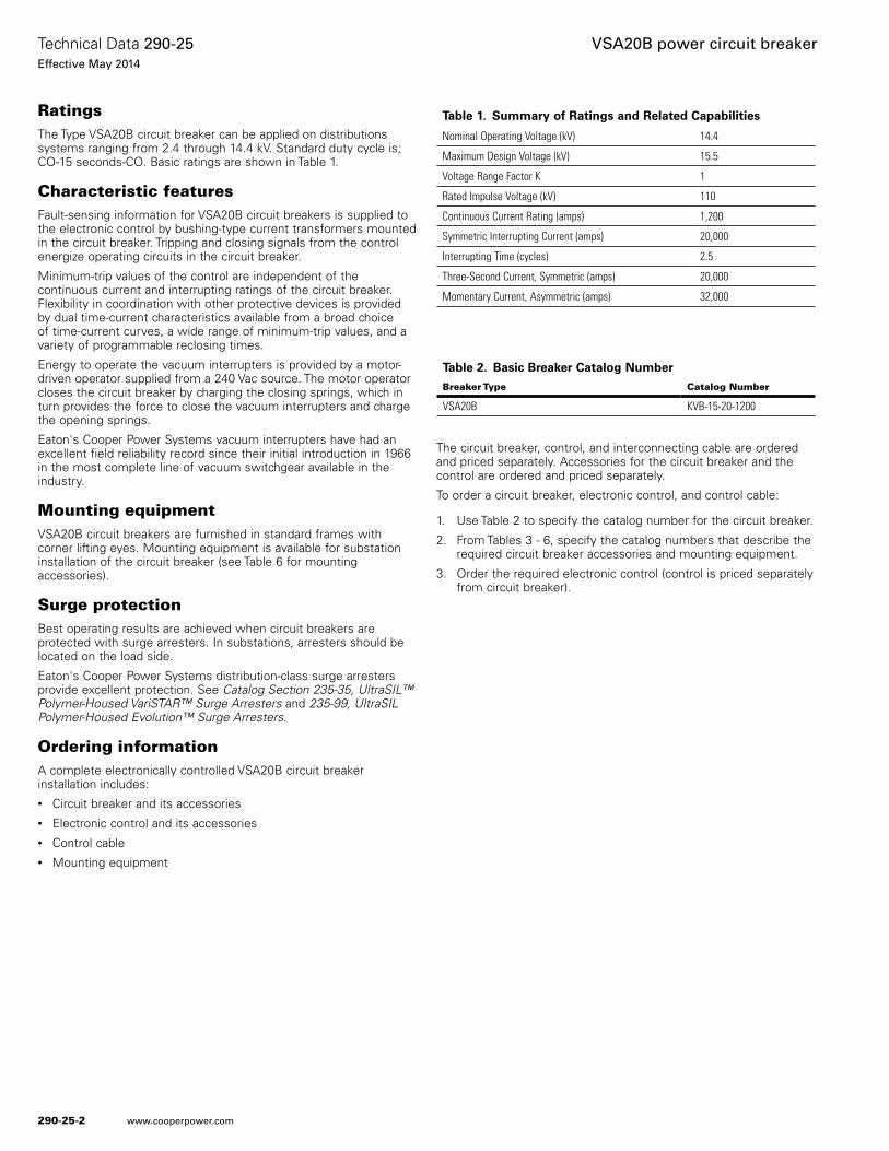
Table 2. Basic Breaker Catalog Number
Breaker Type Catalog Number
VSA20B KVB-15-20-1200
Table 1. Summary of Ratings and Related Capabilities
Nominal Operating Voltage (kV) 14.4
Maximum Design Voltage (kV) 15.5
Voltage Range Factor K 1
Rated Impulse Voltage (kV) 110
Continuous Current Rating (amps) 1,200
Symmetric Interrupting Current (amps) 20,000
Interrupting Time (cycles) 2.5
Three-Second Current, Symmetric (amps) 20,000
Momentary Current, Asymmetric (amps) 32,000
290-25-2
Technical Data 290-25Effective May 2014
VSA20B power circuit breaker
www.cooperpower.com
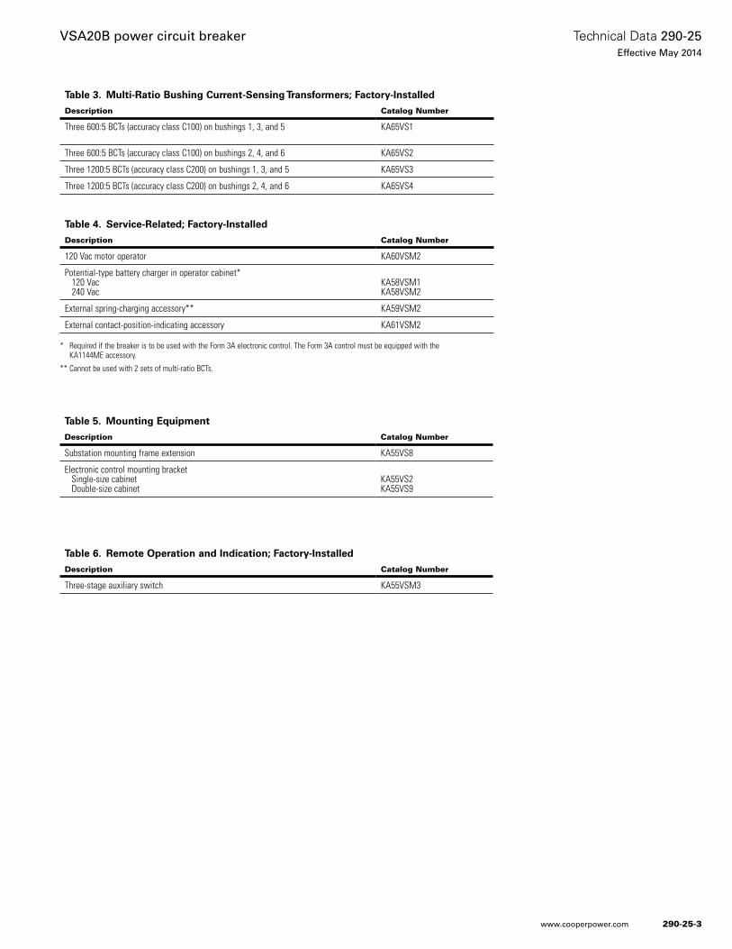
Table 3. Multi-Ratio Bushing Current-Sensing Transformers; Factory-Installed
Description Catalog Number
Three 600:5 BCTs (accuracy class C100) on bushings 1, 3, and 5 KA65VS1
Three 600:5 BCTs (accuracy class C100) on bushings 2, 4, and 6 KA65VS2
Three 1200:5 BCTs (accuracy class C200) on bushings 1, 3, and 5 KA65VS3
Three 1200:5 BCTs (accuracy class C200) on bushings 2, 4, and 6 KA65VS4
* Required if the breaker is to be used with the Form 3A electronic control. The Form 3A control must be equipped with the KA1144ME accessory.
** Cannot be used with 2 sets of multi-ratio BCTs.
Table 6. Remote Operation and Indication; Factory-Installed
Description Catalog Number
Three-stage auxiliary switch KA55VSM3
Table 5. Mounting Equipment
Description Catalog Number
Substation mounting frame extension KA55VS8
Electronic control mounting bracket Single-size cabinet Double-size cabinet
KA55VS2KA55VS9
Table 4. Service-Related; Factory-Installed
Description Catalog Number
120 Vac motor operator KA60VSM2
Potential-type battery charger in operator cabinet* 120 Vac 240 Vac
KA58VSM1KA58VSM2
External spring-charging accessory** KA59VSM2
External contact-position-indicating accessory KA61VSM2
290-25-3
Technical Data 290-25Effective May 2014
VSA20B power circuit breaker
www.cooperpower.com
Circuit breakerVSA20B circuit breakers feature vacuum interruption with air insulation and low-voltage motor operation. VSA20B circuit breakers are designed for circuit protection on systems operating through 14.4 kV.
Because of the large selection of trip ratings and the flexibility provided by Eaton's Cooper Power Systems electronic controls, VSA20B circuit breakers can be applied to meet a wide variety of requirements.
The vacuum interrupters in VSA20B circuit breakers provide reliable, shock-free fault-current interruption with long interrupter life. The combination of vacuum interruption and air insulation provides longer maintenance intervals and lower maintenance costs than comparable oil-insulated circuit breakers. Vacuum interruption also provides greater safety for indoor applications than arc interruption in oil.
Closing and tripping operations of the circuit breaker are both powered by springs. The motor operator loads the closing springs, which charge the opening springs during closing.
An external 240 Vac source is required to supply power for the motor operator and the cabinet heaters. The 240 Vac supply is not required to trip the circuit breaker.
Fault currents are sensed by 2000:1-ratio bushing current transformers mounted in the circuit breaker, which provide sensing of both phase and ground (zero sequence) currents. They provide a continuous measurement of line current that is monitored by the circuit breaker control. When the control’s programmed minimum trip level is exceeded, the control energizes the trip solenoid in the circuit breaker operating mechanism, opening the circuit breaker.
ConstructionEaton's Cooper Power Systems air-insulated vacuum circuit breakers offer extra-long service life and require minimal maintenance. Vacuum interrupter contacts, as well as the entire circuit breaker, require no service other than periodic maintenance inspection.
Housings are fabricated of hot-rolled steel which is phosphatized to resist corrosion, then finished with polyester powder paint. Finish color is light gray, Munsell 5BG 7.0/0.4.
Nonferrous alloys are used for mechanism linkages; stainless steel is used for shafts and hardware. Other steel parts are plated. Needle bearing or hard brass bushings are swaged into mechanism plates and linkages to provide long, trouble-free life for moving parts.
All gears and latches are permanently lubricated; sealed ball bearings are used in the motor.
For ease of inspection, all internal parts are readily accessible by removing an inspection panel on either side of the circuit breaker.
Vacuum interrupters are mounted independently of the bushings. The bushing rods clamp to a current transfer member of the inter-rupter mounting assembly. Therefore, the bushings can be replaced quickly and easily without disturbing the interrupter or requiring any interrupter adjustment.
Insulating supports for the three interrupters are made of filament-wound glass epoxy for high electrical and mechanical strength and moisture resistance.
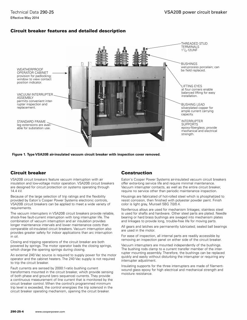
Figure 1. Type VSA20B air-insulated vacuum circuit breaker with inspection cover removed.
Circuit breaker features and detailed description
WEATHERPROOF OPERATOR CABINET provision for padlocking; window to view contact position indicator.
VACUUM INTERRUPTER ASSEMBLY permits convenient inter-rupter inspection and replacement.
STANDARD FRAME leg extensions are avail-able for substation use.
BUSHINGS wet-process porcelain; can be field replaced.
LIFTING EYES at four corners enable balanced lifting for easy installation.
BUSHING LEAD silverplated copper for ample current carrying capacity.
INTERRUPTER SUPPORTSepoxy-fiberglass; provide mechanical and electrical strength.
THREADED STUD TERMINALS 11/4-12UNF
290-25-4
Technical Data 290-25Effective May 2014
VSA20B power circuit breaker
www.cooperpower.com
Cabinet heaters are provided in both the operator mechanism cabinet and the interrupter mechanism cabinet. The heaters are supplied from the 240-Vac auxiliary power source and are connected through a DPST on-off toggle switch and one amp fuses. The mechanism cabinet heater operates at 57 watts. The enclosure heaters operate at 115 watts total.
Motor operation
VSA20B air-insulated, vacuum circuit breakers employ a 240 Vac, motor-driven operating mechanism to charge closing and opening springs.
Tripping
Circuit breaker tripping employs stored spring energy. When line cur-rent exceeds the programmed minimum-trip value, in one or more phases, the control energizes a trip solenoid in the operating mecha-nism. The solenoid trips a latch which releases a spring-loaded toggle assembly, opening the circuit breaker contacts and a switch which interrupts the 24-volt signal from the control. Maximum clearing time is 2 1¼2 cycles.
Tripping, because it employs stored spring energy released by a 24-volt signal from the control, will occur even if the 240-volt supply is lost.
Closing
Closing energy, as well as the force to charge the opening springs, is supplied by the motor operating mechanism, through motor-loaded closing springs. A 240 Vac motor charges the closing springs through a multi-stage gear drive. When 240 Vac is present, the motor is auto-matically operated to keep the closing springs in a charged state.
To close the circuit breaker, the control initiates a signal which ener-gizes a solenoid in the circuit breaker operating mechanism. Once actuated, the solenoid releases the closing springs, which close the vacuum interrupters and charge the opening springs.
Stored energy provides multiple operationsShould the circuit breaker lose 240 Vac motor supply voltage while the closing spring is charged and contacts are closed, an Open-Close-Open sequence remains stored in the circuit breaker operating mechanism. If the circuit breaker trips under these conditions, the stored closing operation allows an immediate reclosing, if required. After such a closing, one additional trip operation then remains stored. Once closed, the circuit breaker always contains energy for at least one trip operation.
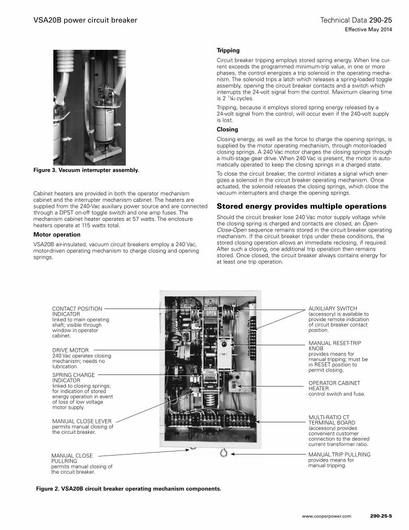
Figure 2. VSA20B circuit breaker operating mechanism components.
Figure 3. Vacuum interrupter assembly.
CONTACT POSITION INDICATOR linked to main operating shaft; visible through window in operator cabinet.
DRIVE MOTOR 240 Vac operates closing mechanism; needs no lubrication.
SPRING CHARGE INDICATOR linked to closing springs; for indication of stored energy operation in event of loss of low voltage motor supply.
MANUAL CLOSE LEVERpermits manual closing of the circuit breaker.
AUXILIARY SWITCH (accessory) is available to provide remote indication of circuit breaker contact position.
MANUAL RESET-TRIP KNOBprovides means for manual tripping; must be in RESET position to permit closing.
OPERATOR CABINET HEATERcontrol switch and fuse.
MULTI-RATIO CTTERMINAL BOARD(accessory) provides convenient customer connection to the desired current transformer ratio.
MANUAL TRIP PULLRINGprovides means for manual tripping.
MANUAL CLOSEPULLRINGpermits manual closing of the circuit breaker.
290-25-5
Technical Data 290-25Effective May 2014
VSA20B power circuit breaker
www.cooperpower.com
Manual operationA closed circuit breaker can be manually tripped from inside the operator cabinet, using the RESET-TRIP knob, or from outside the cabinet by pulling down the Manual Trip Pullring. When the circuit breaker is manually tripped, the closing circuit is opened to prevent reclosing. The circuit breaker can be manually restored to service by placing the RESET-TRIP knob at RESET and moving the manual control switch on the circuit breaker control to CLOSE. The manual control switch on the circuit breaker control panel can also be used for tripping.
The circuit breaker can be manually closed by pulling down the Manual Close Pullring located under the operator cabinet.
An emergency means is provided to manually close a VSA20B circuit breaker on a de-energized line in the absence of the 240 Vac power supply.
A hand crank can be applied to the motor to charge the closing springs. Once charged, the closing springs can be released either from inside or from below the operator mechanism cabinet. As with electrical operations, the opening springs are charged by release of the closing springs, so even a manually closed unit has sufficient stored energy for a trip operation.
Vacuum interruptersThe high quality vacuum interrupters used in VSA20B circuit breakers are manufactured exclusively at Eaton's Cooper Power Systems Switchgear plant. Our vacuum interrupters are used worldwide in the industry’s broadest line of fault protection and switching apparatus, where they have established a proven record of long term reliability.
Vacuum interrupters provide fast, low energy arc interruption with long contact and interrupter life and low mechanical stress. With arc interruption taking place in a vacuum, contact and interrupter life are four times greater than with interruption in oil. At the same time, mechanical stress and wear on the mechanism is substantially reduced. Combined, these factors result in greatly reduced maintenance costs over the life of the circuit breaker.
Vacuum interrupters from Eaton's Cooper Power Systems are designed with a metal-and-ceramic housing for maximum strength. The high-alumina ceramic used in our vacuum interrupters permits a high processing temperature to develop maximum purity of the assembly and is impervious to helium penetration. Metal end closures and the arcing chambers are of high-purity alloys to minimize contamination.
Enclosed in the interrupter is a stationary and a moving contact assembly. The moving contact has a travel of 7/16 in., its shaft passing through a flexible bellows which maintains vacuum integrity.
Contacts are made of a special non-welding alloy.
Because even the smallest amount of internal contamination can significantly shorten a vacuum interrupter’s life, a state-of-the-art clean-room manufacturing facility is used for vacuum interrupter production. Special care is taken to avoid even minute contamination; whether it be from dust particles, machining oils, or human body salts.
Choice of electronic circuit breaker controlsThe operation of a VSA20B circuit breaker is commanded by an electronic control from Eaton's Cooper Power Systems. We offer a choice of two controls that can be used in conjunction with these circuit breakers. This permits the user to select the control that best fits the requirements of each application.
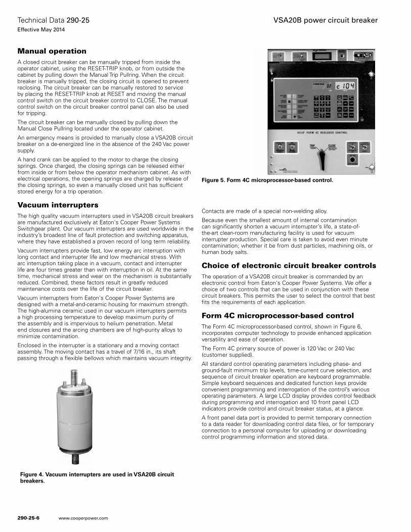
Form 4C microprocessor-based controlThe Form 4C microprocessor-based control, shown in Figure 6, incorporates computer technology to provide enhanced application versatility and ease of operation.
The Form 4C primary source of power is 120 Vac or 240 Vac (customer supplied).
All standard control operating parameters including phase- and ground-fault minimum trip levels, time-current curve selection, and sequence of circuit breaker operation are keyboard programmable. Simple keyboard sequences and dedicated function keys provide convenient programming and interrogation of the control’s various operating parameters. A large LCD display provides control feedback during programming and interrogation and 10 front panel LCD indicators provide control and circuit breaker status, at a glance.
A front panel data port is provided to permit temporary connection to a data reader for downloading control data files, or for temporary connection to a personal computer for uploading or downloading control programming information and stored data.
Figure 4. Vacuum interrupters are used in VSA20B circuit breakers.
Figure 5. Form 4C microprocessor-based control.
290-25-6
Technical Data 290-25Effective May 2014
VSA20B power circuit breaker
www.cooperpower.com
The control is equipped with 41 keyboard-selectable time-current curves which are interchangeable for either phase or ground. Each of the curves can be custom modified to provide almost unlimited coordination flexibility.
The control provides a wide range of standard features, which include: supervisory operation, remote status indication, fault indication via LCD targets and counters, event recorder, circuit breaker duty monitor, demand metering, and load profile monitor.
The microprocessor-based control can be equipped with an accessory supervisory input/output board to extend the supervisory operation capabilities of the control. A fiber optic digital communications accessory is also available for distribution automation applications.
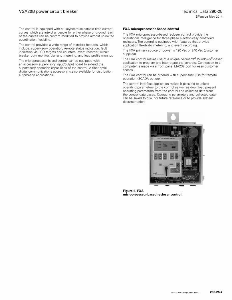
FXA microprocessor-based control
The FXA microprocessor-based recloser control provide the operational intelligence for three-phase electronically controlled reclosers. The control is equipped with features that provide application flexibility, metering, and event recording.
The FXA primary source of power is 120 Vac or 240 Vac (customer supplied).
The FXA control makes use of a unique Microsoft® Windows®-based application to program and interrogate the controls. Connection to a computer is made via a front panel EIA232 port for easy customer access.
The FXA control can be ordered with supervisory I/Os for remote operation (SCADA option).
The control interface application makes it possible to upload operating parameters to the control as well as download present operating parameters from the control and collected data from the control data bases. Operating parameters and collected data can be saved to disk, for future reference or to provide system documentation.
Figure 6. FXA microprocessor-based recloser control.
290-25-7
Technical Data 290-25Effective May 2014
VSA20B power circuit breaker
www.cooperpower.com
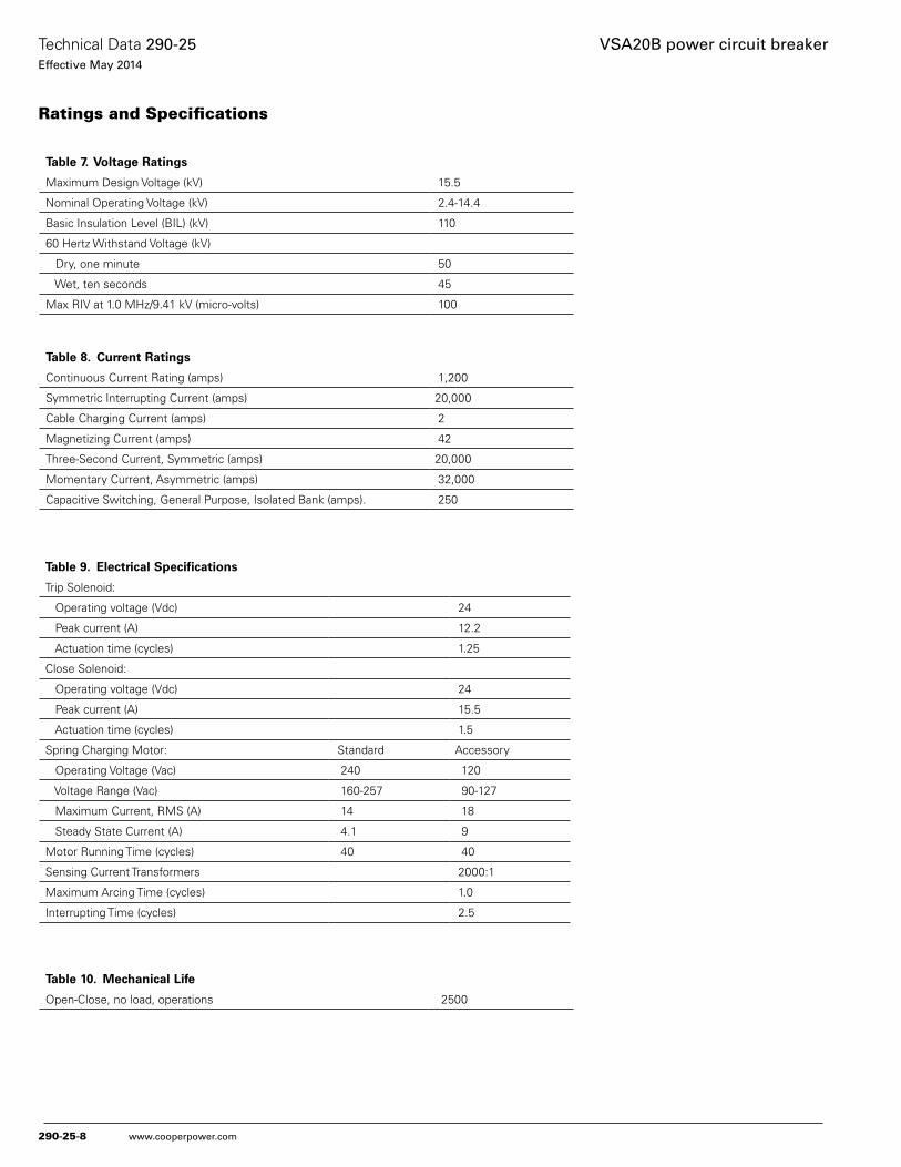
Table 7. Voltage Ratings
Maximum Design Voltage (kV) 15.5
Nominal Operating Voltage (kV) 2.4-14.4
Basic Insulation Level (BIL) (kV) 110
60 Hertz Withstand Voltage (kV)
Dry, one minute 50
Wet, ten seconds 45
Max RIV at 1.0 MHz/9.41 kV (micro-volts) 100
Table 8. Current Ratings
Continuous Current Rating (amps) 1,200
Symmetric Interrupting Current (amps) 20,000
Cable Charging Current (amps) 2
Magnetizing Current (amps) 42
Three-Second Current, Symmetric (amps) 20,000
Momentary Current, Asymmetric (amps) 32,000
Capacitive Switching, General Purpose, Isolated Bank (amps). 250
Table 9. Electrical Specifications
Trip Solenoid:
Operating voltage (Vdc) 24
Peak current (A) 12.2
Actuation time (cycles) 1.25
Close Solenoid:
Operating voltage (Vdc) 24
Peak current (A) 15.5
Actuation time (cycles) 1.5
Spring Charging Motor: Standard Accessory
Operating Voltage (Vac) 240 120
Voltage Range (Vac) 160-257 90-127
Maximum Current, RMS (A) 14 18
Steady State Current (A) 4.1 9
Motor Running Time (cycles) 40 40
Sensing Current Transformers 2000:1
Maximum Arcing Time (cycles) 1.0
Interrupting Time (cycles) 2.5
Ratings and Specifications
Table 10. Mechanical Life
Open-Close, no load, operations 2500
290-25-8
Technical Data 290-25Effective May 2014
VSA20B power circuit breaker
www.cooperpower.com
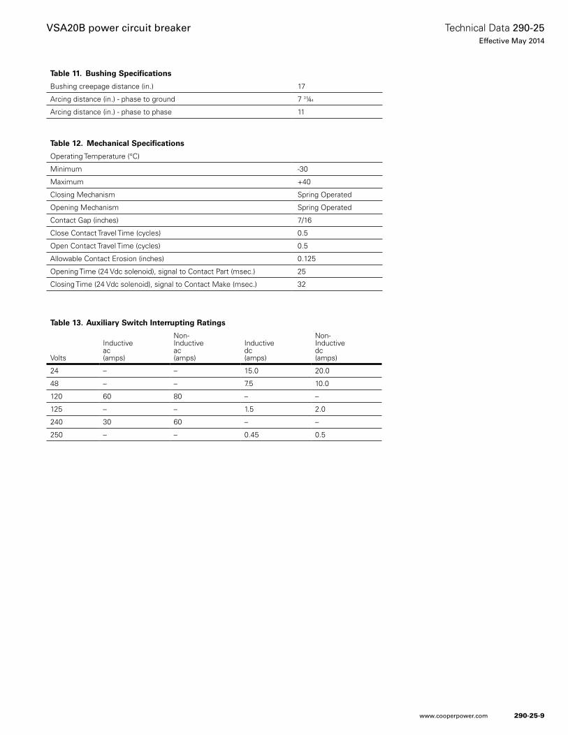
Table 12. Mechanical Specifications
Operating Temperature (°C)
Minimum -30
Maximum +40
Closing Mechanism Spring Operated
Opening Mechanism Spring Operated
Contact Gap (inches) 7/16
Close Contact Travel Time (cycles) 0.5
Open Contact Travel Time (cycles) 0.5
Allowable Contact Erosion (inches) 0.125
Opening Time (24 Vdc solenoid), signal to Contact Part (msec.) 25
Closing Time (24 Vdc solenoid), signal to Contact Make (msec.) 32
Table 13. Auxiliary Switch Interrupting Ratings
Volts
Inductiveac(amps)
Non-Inductiveac(amps)
Inductivedc(amps)
Non-Inductivedc(amps)
24 – – 15.0 20.0
48 – – 7.5 10.0
120 60 80 – –
125 – – 1.5 2.0
240 30 60 – –
250 – – 0.45 0.5
Table 11. Bushing Specifications
Bushing creepage distance (in.) 17
Arcing distance (in.) - phase to ground 7 3¼4
Arcing distance (in.) - phase to phase 11
290-25-9
Technical Data 290-25Effective May 2014
VSA20B power circuit breaker
www.cooperpower.com
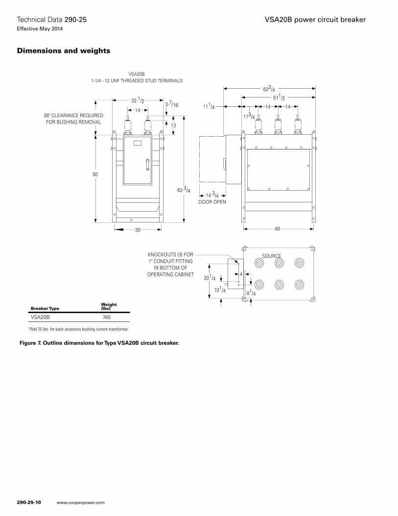
Figure 7. Outline dimensions for Type VSA20B circuit breaker.
26" CLEARANCE REQUIREDFOR BUSHING REMOVAL
50
62-3/4
13
3-7/1614
32-1/2
14 3/4DOOR OPEN
49
623/4511/2
1414
113/4
KNOCKOUTS (3) FOR1" CONDUIT FITTING
IN BOTTOM OFOPERATING CABINET
201/44
81/4101/4
30
VSA20B1-1/4 - 12 UNF THREADED STUD TERMINALS
111/4
SOURCE
Breaker TypeWeight (lbs)
VSA20B 740
*Add 25 lbs. for each accessory bushing current transformer.
Dimensions and weights
290-25-10
Technical Data 290-25Effective May 2014
VSA20B power circuit breaker
www.cooperpower.com
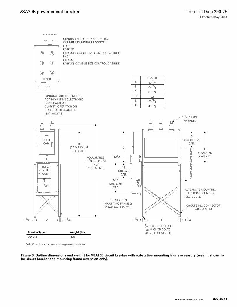
Figure 8. Outline dimensions and weight for VSA20B circuit breaker with substation mounting frame accessory (weight shown is for circuit breaker and mounting frame extension only).
ELEC.CNTRL.
CAB.
OPER.CAB.
A1 1/4 11/4
ADJUSTABLE97 7/8 TO 115 7/8
IN 3"INCREMENTS
343/4DBL. SIZE
CAB.
18STD. SIZE
CAB.
C
131/2
DDOUBLE-SIZE
CAB.
ESTANDARD
CABINET
1 1/4 1-1/4F
GROUNDING CONNECTOR2/0-250 MCM
3/4 DIA. HOLES FOR5/8 ANCHOR BOLTS(4), NOT FURNISHED
ALTERNATE MOUNTINGELECTRONIC CONTROL(SEE DETAIL)
OPTIONAL ARRANGEMENTSFOR MOUNTING ELECTRONIC CONTROL (FORCLARITY, OPERATOR ONFRONT OF RECLOSER ISNOT SHOWN)
STANDARD ELECTRONIC CONTROL CABINET MOUNTING BRACKETS:FRONTKA55VS2KA55VS4 (DOUBLE-SIZE CONTROL CABINET)BACKKA55VS3KA55VS5 (DOUBLE-SIZE CONTROL CABINET)
A
B
C
D
E
F
VSA20B
30 1/2
84 7/8
39 1/4
22
38 3/4
49 1/2
B(AT MINIMUM
HEIGHT)
FRONT
SUBSTATIONMOUNTING FRAMES:VSA20B — KA55VS8
1 1/4-12 UNFTHREADED
Breaker Type Weight (lbs)
VSA20B 890
*Add 25 lbs. for each accessory bushing current transformer.
290-25-11
Technical Data 290-25Effective May 2014
VSA20B power circuit breaker
www.cooperpower.com
Eaton, Cooper Power Systems, UltraSIL, and Evolution, are valuable trademarks of Eaton in the U.S. and other countries. You are not per-mitted to use the these trademarks without the prior written consent of Eaton.IEEE® is a registered trademark of the Institute of Electrical and Electronics Engineers, Inc.ANSI® is a registered trademark of American National Standards Institute.NEMA® is a registered trademark of the National Electrical Manufacturers Association.Microsoft® and Windows® are registered trademarks of Micorsoft.
VSA20B power circuit breaker
Eaton1000 Eaton BoulevardCleveland, OH 44122United StatesEaton.com
Eaton’s Cooper Power Systems Business2300 Badger DriveWaukesha, WI 53188United StatesCooperpower.com
© 2014 EatonAll Rights ReservedPrinted in USAPublication No. 290-25May 2014
Technical Data 290-25Effective May 2014
For Eaton’s Cooper Power Systems VSA20B power circuit breaker product information call 1-877-277-4636 or visit: www.cooperpower.com.
290-25-12

Eaton and Cooper Power Systems are valuable trademarks of Eaton in the U .S . and other countries . You are not permitted to use these trademarks without the prior written consent of Eaton .
All other trademarks are property of their respective owners .
Eaton1000 Eaton BoulevardCleveland, OH 44122United StatesEaton .com
Eaton’s Cooper Power Systems Business2300 Badger DriveWaukesha, WI 53186United States CooperPower .com
© 2014 EatonAll Rights ReservedPrinted in USA