Embed Size (px)
Citation preview
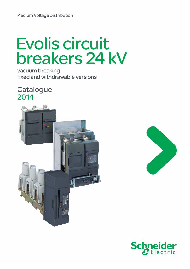
Medium Voltage Distribution
Evolis circuit breakers 24 kV vacuum breakingfixed and withdrawable versions
Catalogue 2014

1AMTED307011EN.indd
General contentsEvolis circuit breakers 24 kV
General presentation 2
Panorama 8
Evolis 24 kV fixed, frontal version 11
Evolis 24 kV withdrawable, frontal version 25
Evolis 24 kV fixed, lateral version 45
EVOset 24 kV fixed, lateral version 57
2 AMTED307011EN.indd
Evolis: a range of circuit breakers that takes account of your electrical installations’ requirements today and in the future.
DescriptionEvolis: a range of vacuum-type circuit breakers from 7.2 kV to 24 kV, combining easy selection and a comprehensive offer:
b a fixed, frontal or lateral version b a withdrawable, frontal version with a circuit breaker and its cradle or its cassette b a fixed, lateral version equipped with an integrated protection chain b separately delivered accessories.
The Evolis circuit breaker is operated via a spring mechanism that gives an operating speed that is independent of the operator and that does not require an auxiliary power supply.When the operating mechanism is motorized the circuit breaker can include telecontrol functions and carry out rapid reclosing cycles.The various circuit breaker versions are easy to integrate in a cubicle environment. An Installation Guide details the required procedure.
ApplicationsEvolis is intended for use in medium voltage network applications, in new installations or renovation, for utilities companies, infrastructures, the process industry and the tertiary sector.It provides protection for all types of applications: cables, overhead lines, motors, capacitors, transformers, source busbar sections, etc.
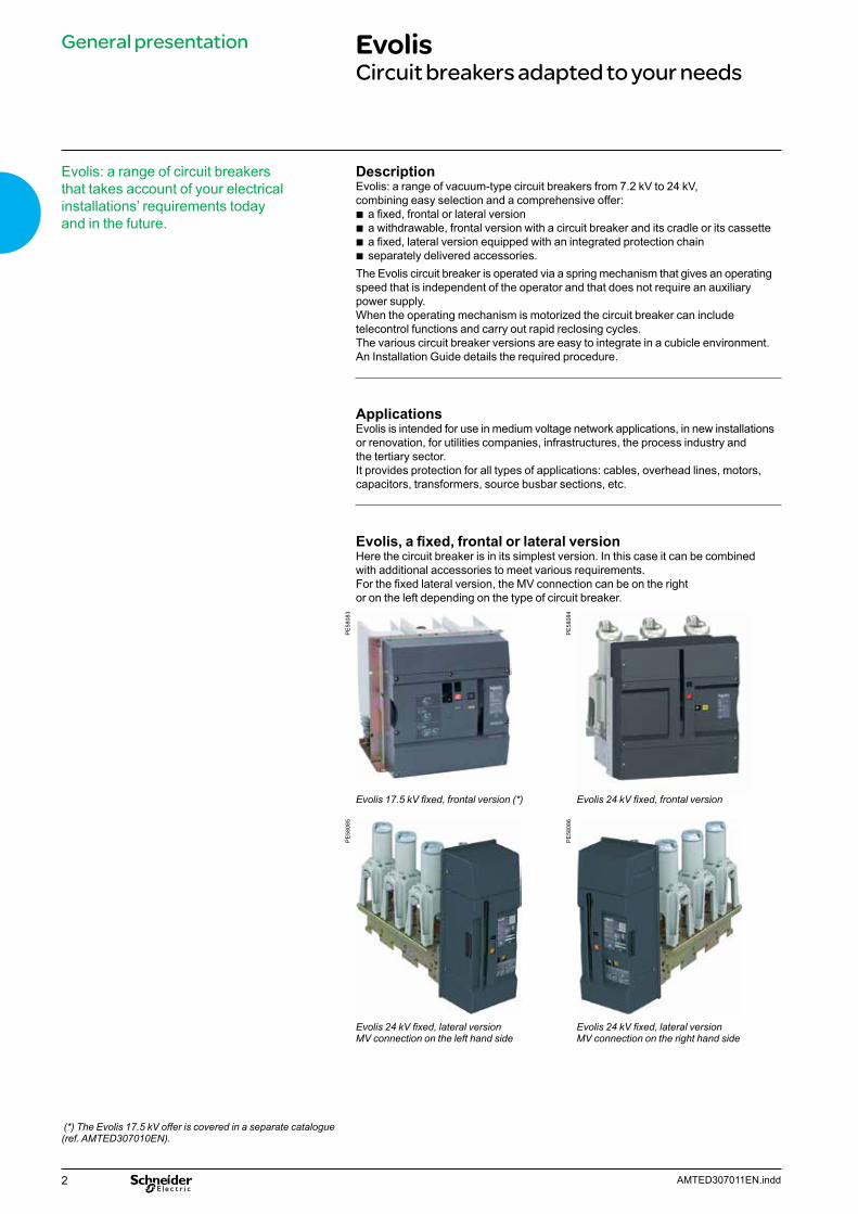
Evolis, a fixed, frontal or lateral versionHere the circuit breaker is in its simplest version. In this case it can be combined with additional accessories to meet various requirements.For the fixed lateral version, the MV connection can be on the rightor on the left depending on the type of circuit breaker.
PE
5808
3
PE
5808
4
Evolis 17.5 kV fixed, frontal version (*) Evolis 24 kV fixed, frontal version
PE
5808
5
PE
5808
6
Evolis 24 kV fixed, lateral versionMV connection on the left hand side
Evolis 24 kV fixed, lateral versionMV connection on the right hand side
General presentation EvolisCircuit breakers adapted to your needs
(*) The Evolis 17.5 kV offer is covered in a separate catalogue (ref. AMTED307010EN).
3AMTED307011EN.indd
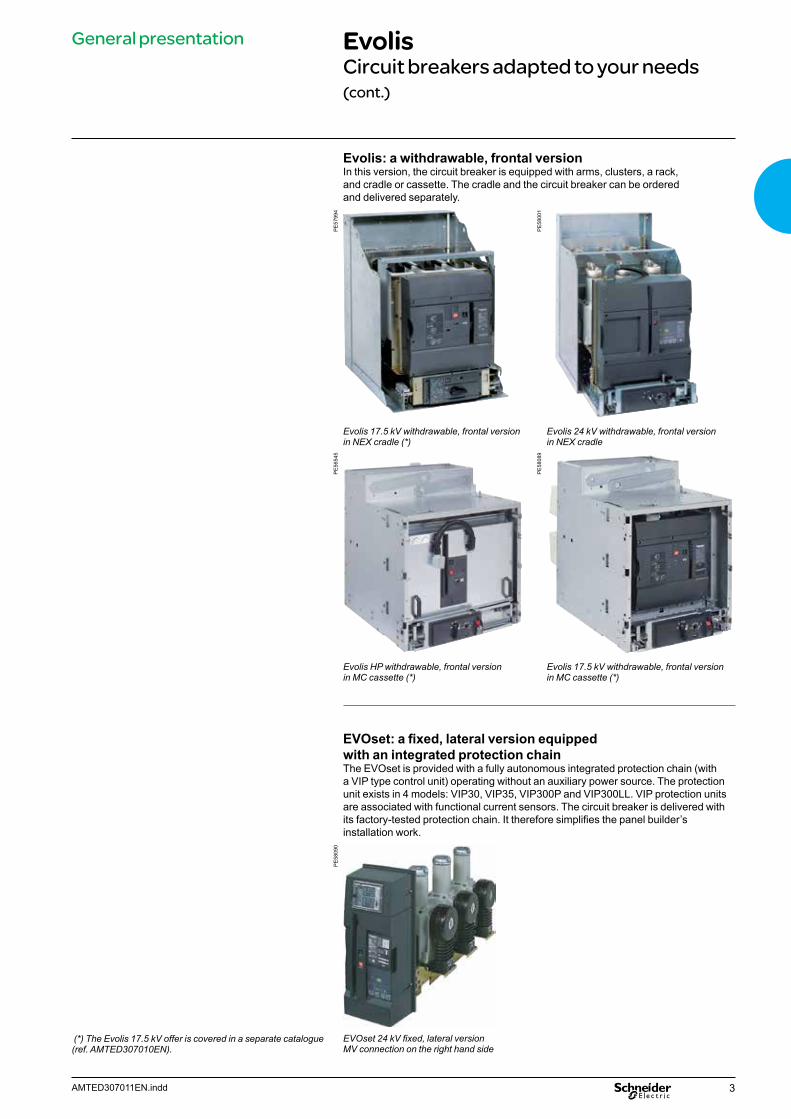
Evolis: a withdrawable, frontal versionIn this version, the circuit breaker is equipped with arms, clusters, a rack, and cradle or cassette. The cradle and the circuit breaker can be ordered and delivered separately.
PE
5799
4
PE
5800
1
Evolis 17.5 kV withdrawable, frontal version in NEX cradle (*)
Evolis 24 kV withdrawable, frontal version in NEX cradle
PE
5654
5
PE
5808
9
Evolis HP withdrawable, frontal version in MC cassette (*)
Evolis 17.5 kV withdrawable, frontal version in MC cassette (*)
EVOset: a fixed, lateral version equipped with an integrated protection chainThe EVOset is provided with a fully autonomous integrated protection chain (with a VIP type control unit) operating without an auxiliary power source. The protection unit exists in 4 models: VIP30, VIP35, VIP300P and VIP300LL. VIP protection units are associated with functional current sensors. The circuit breaker is delivered with its factory-tested protection chain. It therefore simplifies the panel builder’s installation work.
PE
5809
0
EVOset 24 kV fixed, lateral versionMV connection on the right hand side
General presentation EvolisCircuit breakers adapted to your needs (cont.)
(*) The Evolis 17.5 kV offer is covered in a separate catalogue (ref. AMTED307010EN).

4 AMTED307011EN.indd
General presentation EvolisThe very best of vacuum technology
As a specialist in breaking technologies, Schneider Electric took naturally an interest in vacuum breaking techniques.A major R&D investment was made to develop and engineer Evolis, providing customers with the very best of vacuum technology.
Make-up of a vacuum interrupterVacuum interrupters basically have two electrical contacts (fig.1), one fixed and the other mobile, and a sealed enclosure. The latter enables a high level of vacuum to be maintained inside the interrupter (less than 10-2 Pa) to provide insulation between the open contacts.The dielectric strength of the vacuum allows the contact-to-contact distance to be reduced. This short distance together with the low opening speed allow the use of a low energy control mechanism. A metal clusters provides the link between the mobile contact and the enclosure.In order to keep the vacuum level required for the correct operation of the interrupter for 30 years, the enclosure must be perfectly sealed, and the various components have to be fully degased. This is achieved by:
b choosing materials that are specifically selected for this application (metals and ceramics)
b choosing an appropriate assembly process (vacuum, high temperature brazing) b the use of a “getter” material to absorb the residual gas.
Current breaking in a vacuum interrupterIn vacuum breaking, the electrical arc generated on separation of the contacts is made up of a plasma of metal vapors produced by the vaporization of the contact material.At low values of current, these vapors very quickly condense on the shield and contacts when the arc disappears, thus allowing:
b the vacuum to be re-established b a contact-to-contact dielectric strength to be restored that is greater than b the recovery voltage: breaking is then complete.
At high currents, the electrical arc in the vacuum switches to a concentrated mode which causes high, localized temperature rises on the contacts. The existence of these hot spots is detrimental to the quick restoring of the dielectric strength.Two techniques can be used in order to avoid this stagnation of the static concentrated arc:
b the so called RMF (Radial Magnetic Field) technique, involves rotating the arc thanks to an electromagnetic effect generated by a radial magnetic field; this therefore limits contact erosion.
b a more recent technique called AMF (Axial Magnetic Field) involves applying an axial magnetic field parallel to the axis of the two contacts (fig. 2) which allows a diffuse arc to be maintained (fig. 3) even at high current values. The arc energy is spread over the whole contact surface area, therefore causing very low levels of erosion.
b Schneider Electric has chosen this last technique for the Evolis range.
PE
6004
2
Fig. 3: diffuse vacuum arc AMF technology
DE
6016
3
Fig. 1: vacuum interrupter components
Ceramic chamber
Fixed contactShield
Mobile contact
Metal bellows
DE
6016
4
Fig. 2: cross-section of AMF contact
Electrode
Current
AMF coilContact diskArc plasma
Axial magnetic field

5AMTED307011EN.indd
General presentation EvolisThe very best of vacuum technology (cont.)
Schneider Electric’s choices for Evolis combined with its industrial expertise provides customer with a highly reliable range of circuit breakers. These products are suitable for the most demanding conditions with the guarantee of full compliance with international standards.
AMF technologyEvolis circuit breakers use AMF type vacuum interrupters. According to technical and economic optimization considerations, the axial magnetic field is generated:
b either by a coil outside of the interrupter (fig. 4), for rated voltages up to 17.5 kV b or by a coil integrated in the interrupter contact structure (fig. 5), for the 24 kV
voltage level.In both cases the AMF vacuum interrupters feature low arc voltages (Uarc of around 50 V) and maximum usage of the contact surface for very low contact erosion.
The advantages providedThe above choices provide customers with the following advantages in MV circuit breaker applications:
b simple and compact vacuum interrupters b high electrical endurance meaning that there is no need for contact wear
inspection in normal network protection applications including highly disturbed overhead line feeders.
2001
10
Fig. 4: 17.5 kV external coil type interrupter
DE
6016
2
Fig. 5: 24 kV internal coil type interrupter
6 AMTED307011EN.indd
General presentation EvolisThe very best of vacuum technology (cont.)
PE
5569
4
Vacuum interrupter
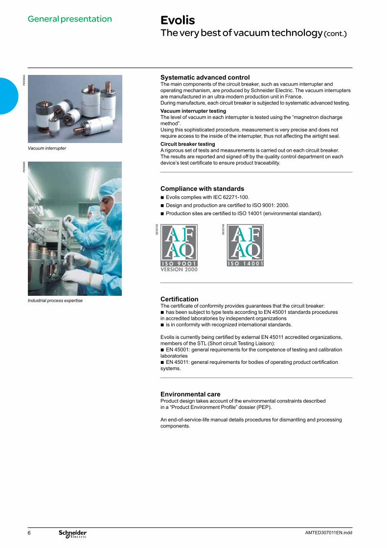
Systematic advanced controlThe main components of the circuit breaker, such as vacuum interrupter and operating mechanism, are produced by Schneider Electric. The vacuum interrupters are manufactured in an ultra-modern production unit in France.During manufacture, each circuit breaker is subjected to systematic advanced testing.Vacuum interrupter testingThe level of vacuum in each interrupter is tested using the “magnetron discharge method”.Using this sophisticated procedure, measurement is very precise and does not require access to the inside of the interrupter, thus not affecting the airtight seal.Circuit breaker testingA rigorous set of tests and measurements is carried out on each circuit breaker.The results are reported and signed off by the quality control department on each device’s test certificate to ensure product traceability.
Compliance with standards b Evolis complies with IEC 62271-100. b Design and production are certified to ISO 9001: 2000. b Production sites are certified to ISO 14001 (environmental standard).
DE
5574
5
DE
5574
6
CertificationThe certificate of conformity provides guarantees that the circuit breaker:
b has been subject to type tests according to EN 45001 standards procedures in accredited laboratories by independent organizations
b is in conformity with recognized international standards.
Evolis is currently being certified by external EN 45011 accredited organizations, members of the STL (Short circuit Testing Liaison):
b EN 45001: general requirements for the competence of testing and calibration laboratories
b EN 45011: general requirements for bodies of operating product certification systems.
Environmental careProduct design takes account of the environmental constraints described in a “Product Environment Profile” dossier (PEP).
An end-of-service-life manual details procedures for dismantling and processing components.
PE
5569
5
Industrial process expertise

7AMTED307011EN.indd
General presentation EvolisExtended products offer
Circuit breakerb cradle
Instrumenttransformer
MV cubicle componentsb capacitor insulatorb earthing switchb heating resistorb voltage presence indicatorb crankb extraction table
LV cubiclecomponentsb Mcbb protection relayb lampb push buttonb terminal blocks connector
Protection and controlb UMI
Meteringb VPISb PM700 or PM800
PE
5808
2
8 AMTED307011EN.indd
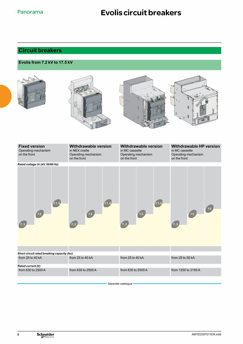
Circuit breakers
Evolis from 7.2 kV to 17.5 kV
Ur=12kV
Up=75kV
Ir=630A
Isc=25kA tK=4s
Ud=42kV (50Hz 1min)
Seq=O-0,3s-CO-15s-CO
IEC 62271-100 Ed 1.1 20003-05
GB 1984
DL/T 402
N°:
fr=50Hz
Evolis
Ur=12kV
Up=75kV
Ir=630A
Isc=25kA tK=4s
Ud=42kV (50Hz 1min)
Seq=O-0,3s-CO-15s-CO
IEC 62271-100 Ed 1.1 20003-05
GB 1984
DL/T 402
N°:
fr=50Hz
Evolis
Ur=12kV
Up=75kV
Ir=630A
Isc=25kA tK=4s
Ud=42kV (50Hz 1min)
Seq=O-0,3s-CO-15s-CO
IEC 62271-100 Ed 1.1 20003-05
GB 1984
DL/T 402
N°:
fr=50Hz
Evolis
Fixed versionOperating mechanism on the front
Withdrawable versionin NEX cradleOperating mechanism on the front
Withdrawable versionin MC cassetteOperating mechanism on the front
Withdrawable HP versionin MC cassetteOperating mechanism on the front
Rated voltage Ur (kV, 50/60 Hz)
Short circuit rated breaking capacity (Isc)from 25 to 40 kA from 25 to 40 kA from 25 to 40 kA from 25 to 50 kA
Rated current (Ir)from 630 to 2500 A from 630 to 2500 A from 630 to 2500 A from 1250 to 3150 A
Separate catalogue
Panorama Evolis circuit breakers
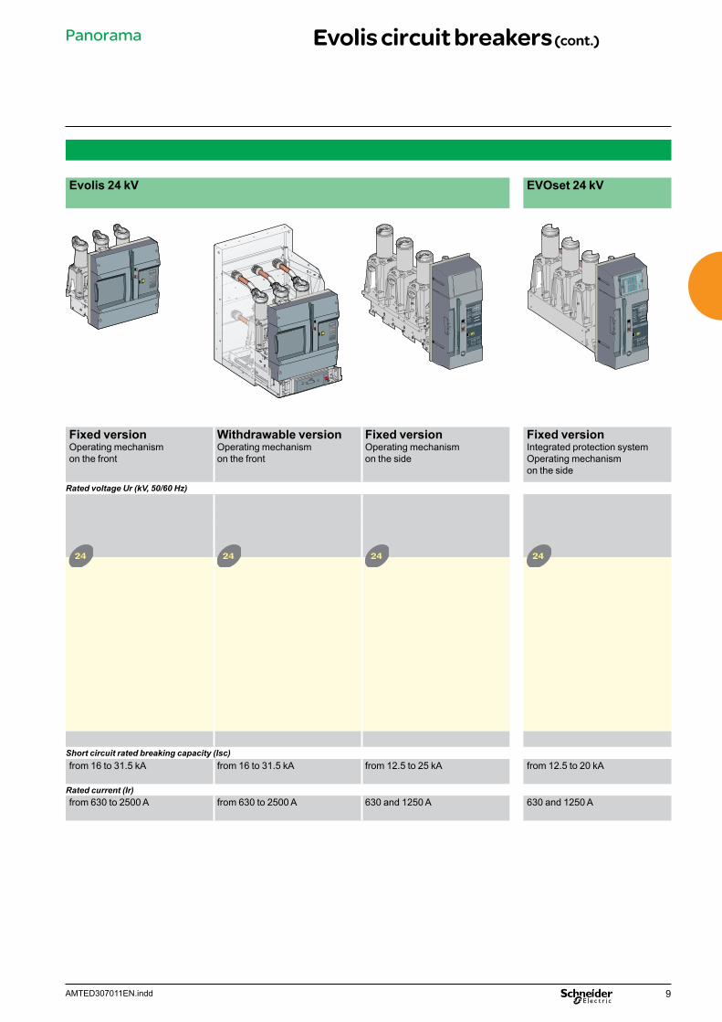
9AMTED307011EN.indd
Evolis 24 kV EVOset 24 kV
Ur = 24 kV
Up = 75kV
Ir = 630A
Isc = 25kA tK=4s
Ud = 42kV (50Hz 1min)
Seq = O-0,3s-CO-15s-CO
IEC 62271-100 Ed 1.1 20003-05
GB 1984
DL/T 402
fr = 50Hz
Ur = 24 kV
Up = 75kV
Ir = 630A
Isc = 25kA tK=4s
Ud = 42kV (50Hz 1min)
Seq = O-0,3s-CO-15s-CO
IEC 62271-100 Ed 1.1 20003-05
GB 1984
DL/T 402
fr = 50Hz
Fixed versionOperating mechanism on the front
Withdrawable versionOperating mechanism on the front
Fixed versionOperating mechanism on the side
Fixed versionIntegrated protection systemOperating mechanism on the side
Rated voltage Ur (kV, 50/60 Hz)
Short circuit rated breaking capacity (Isc)from 16 to 31.5 kA from 16 to 31.5 kA from 12.5 to 25 kA from 12.5 to 20 kA
Rated current (Ir)from 630 to 2500 A from 630 to 2500 A 630 and 1250 A 630 and 1250 A
Panorama Evolis circuit breakers (cont.)
10 AMTED307011EN.indd
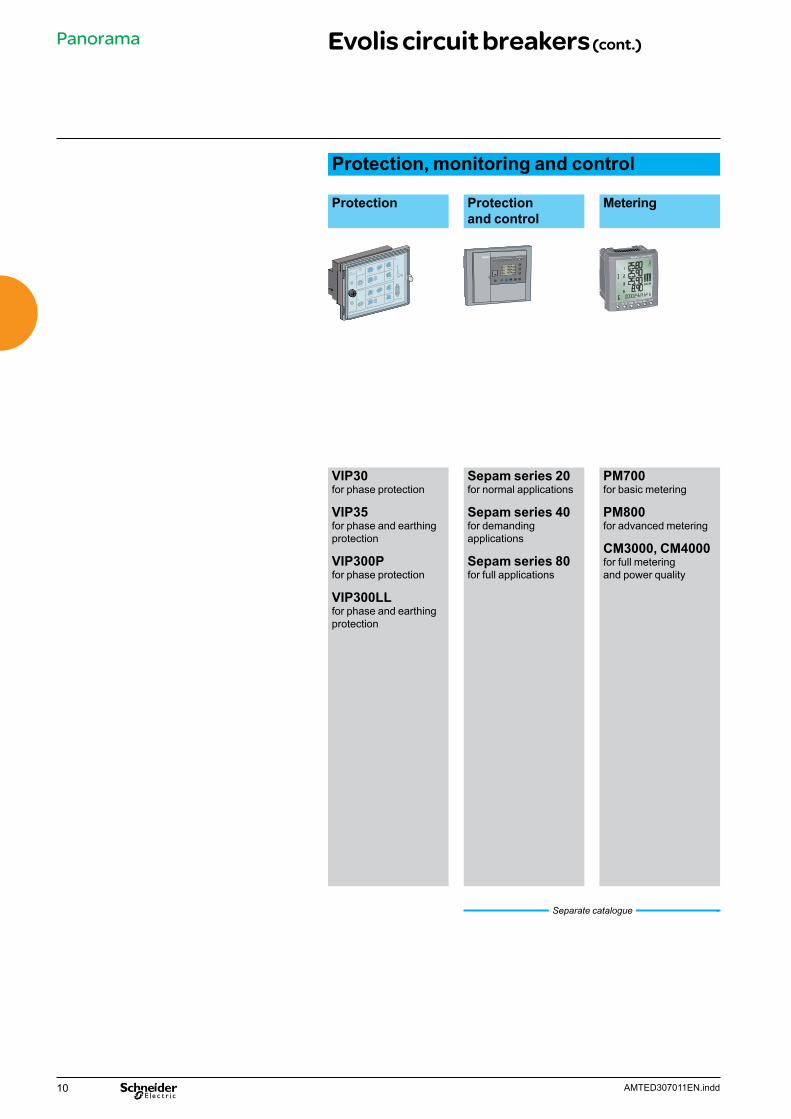
Protection, monitoring and control
Protection Protection and control
Metering
Sepam
I1 = 165A RMS
I2 = 166A RMS
I3 = 167A RMS
onext
1 > 51 1o > 511 > >51 1o > >510 off I on Trip
VIP30for phase protection
VIP35for phase and earthing protection
VIP300Pfor phase protection
VIP300LLfor phase and earthing protection
Sepam series 20for normal applications
Sepam series 40for demanding applications
Sepam series 80for full applications
PM700for basic metering
PM800for advanced metering
CM3000, CM4000for full meteringand power quality
Separate catalogue
Panorama Evolis circuit breakers (cont.)
11AMTED307011EN.indd
Presentation 12Main characteristics 13Description of functions 14MV connection 14LV connection 15RI stored energy operating mechanism 16Wiring diagram 16Opening circuit 17Remote control 18Indication and locking/interlocking 19
Dimensions 20Order form 21Offer structure 22Separated components 22
Services 24
Evolis 24 kV fixed, frontal version
Contents
12 AMTED307011EN.indd
Evolis 24 kV fixed, frontal version
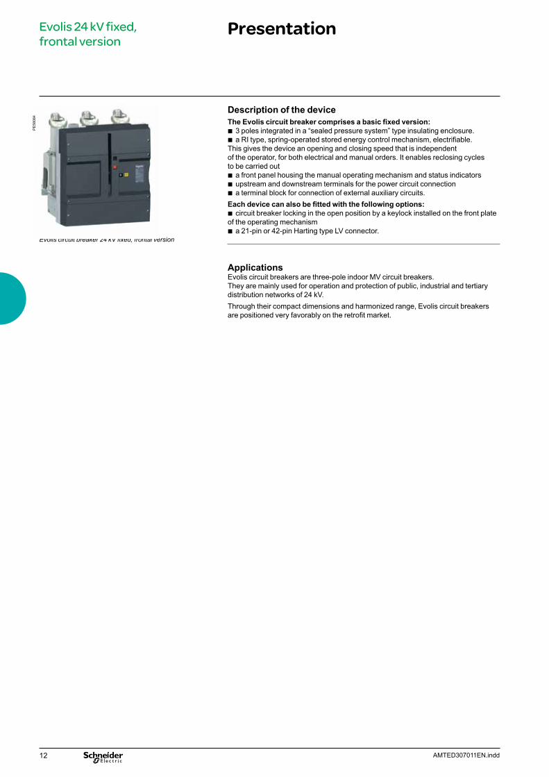
Presentation
Description of the device The Evolis circuit breaker comprises a basic fixed version:
b 3 poles integrated in a “sealed pressure system” type insulating enclosure. b a RI type, spring-operated stored energy control mechanism, electrifiable.
This gives the device an opening and closing speed that is independent of the operator, for both electrical and manual orders. It enables reclosing cycles to be carried out
b a front panel housing the manual operating mechanism and status indicators b upstream and downstream terminals for the power circuit connection b a terminal block for connection of external auxiliary circuits.
Each device can also be fitted with the following options: b circuit breaker locking in the open position by a keylock installed on the front plate
of the operating mechanism b a 21-pin or 42-pin Harting type LV connector.
Applications Evolis circuit breakers are three-pole indoor MV circuit breakers. They are mainly used for operation and protection of public, industrial and tertiary distribution networks of 24 kV. Through their compact dimensions and harmonized range, Evolis circuit breakers are positioned very favorably on the retrofit market.
Evolis circuit breaker 24 kV fixed, frontal version
PE
5808
4
13AMTED307011EN.indd
Evolis 24 kV fixed, frontal version
Main characteristics
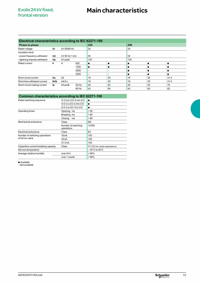
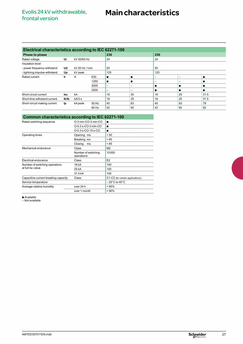
Electrical characteristics according to IEC 62271-100Phase to phase 230 250
Rated voltage Ur kV 50/60 Hz 24 24Insulation level- power frequency withstand Ud kV 50 Hz 1 min 50 50- lightning impulse withstand Up kV peak 125 125Rated current Ir A 630 b b b b b
1250 b b b b b
2000 – – b b b
2500 – – b b b
Short circuit current Isc kA 16 25 16 25 31.5Short time withstand current Ik/tk kA/3 s 16 25 16 25 31.5Short-circuit making current Ip kA peak 50 Hz 40 63 40 63 79
60 Hz 42 65 42 65 82
Common characteristics according to IEC 62271-100Rated switching sequence O-3 min-CO-3 min-CO b
O-0.3 s-CO-3 min-CO b
O-0.3 s-CO-15 s-CO b
Operating times Opening ms < 50Breaking ms < 65Closing ms < 85
Mechanical endurance Class M2Number of switching operations
10 000
Electrical endurance Class E2Number of switching operations at full Isc value
16 kA 10025 kA 10031.5 kA 100
Capacitive current breaking capacity Class C1-C2 (for certain applications)
Service temperature – 25°C to 40°CAverage relative humidity over 24 h < 95%
over 1 month < 90%
b Available– Not available
14 AMTED307011EN.indd
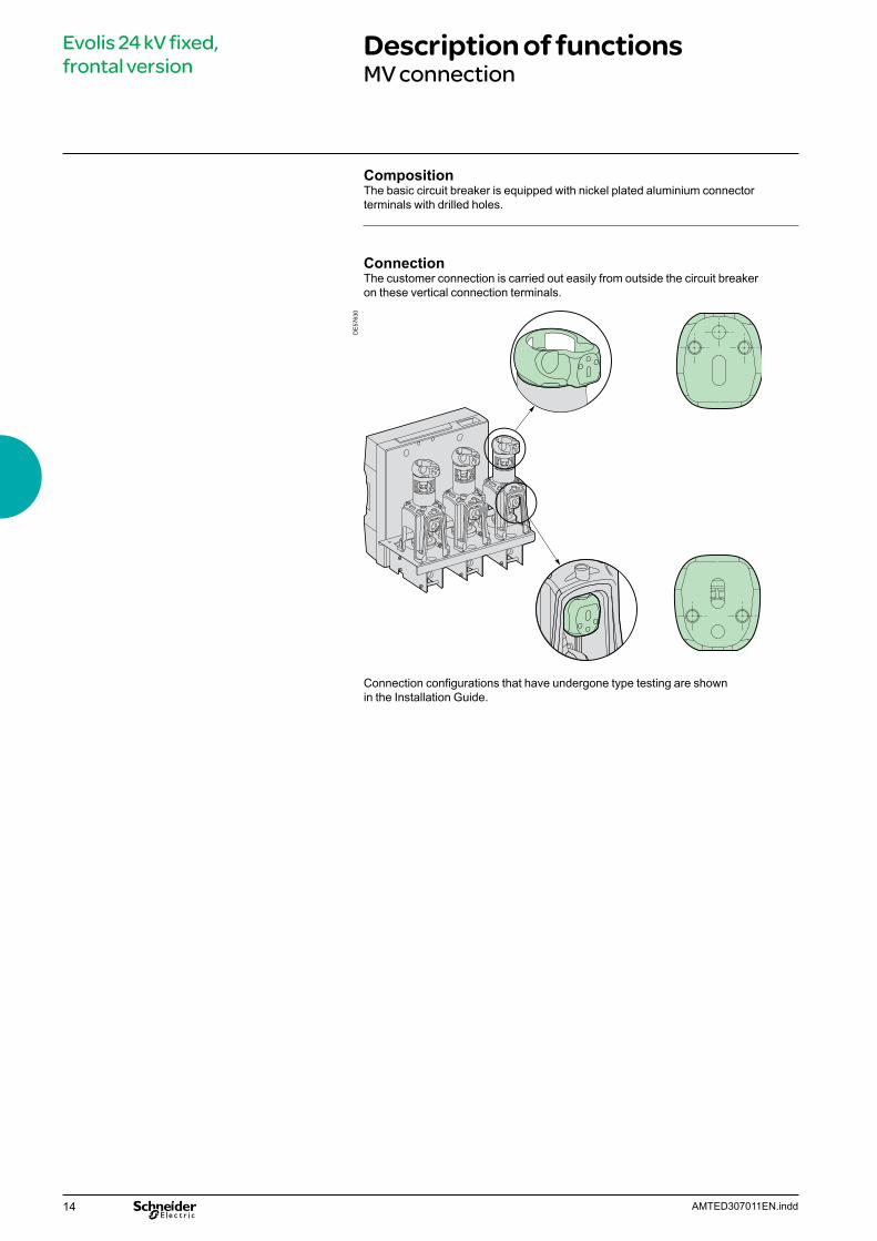
CompositionThe basic circuit breaker is equipped with nickel plated aluminium connector terminals with drilled holes.
ConnectionThe customer connection is carried out easily from outside the circuit breaker on these vertical connection terminals.
DE
5763
0
Connection configurations that have undergone type testing are shown in the Installation Guide.
Evolis 24 kV fixed, frontal version
Description of functionsMV connection
15AMTED307011EN.indd
Evolis 24 kV fixed, frontal version
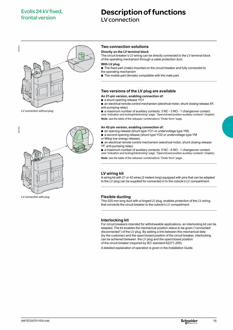
Description of functionsLV connection
Two connection solutionsDirectly on the LV terminal blockThe circuit breaker’s LV wiring can be directly connected to the LV terminal block of the operating mechanism through a cable protection duct.With LV plug
b The fixed part (male) mounted on the circuit breaker and fully connected to the operating mechanism
b The mobile part (female) compatible with the male part.
Two versions of the LV plug are availableAn 21-pin version, enabling connection of:
b a shunt opening release YO1 b an electrical remote control mechanism (electrical motor, shunt closing release XF,
anti-pumping relay) b a maximum number of auxiliary contacts: 3 NC - 3 NO - 1 changeover contact.
(see “indication and locking/interlocking” page, “Open/closed position auxiliary contacts” chapter).Note: see the table of the releases’ combinations “Order form” page.
An 42-pin version, enabling connection of: b an opening release (shunt type YO1 or undervoltage type YM) b a second opening release (shunt type YO2 or undervoltage type YM
or Mitop low energy release) b an electrical remote control mechanism (electrical motor, shunt closing release
YF, anti-pumping relay) b a maximum number of auxiliary contacts: 5 NC - 6 NO - 1 changeover contact.
(see “indication and locking/interlocking” page, “Open/closed position auxiliary contacts” chapter).
Note: see the table of the releases’ combinations “Order form” page.
LV wiring kitA wiring kit with 21 or 42 wires (2 meters long) equipped with pins that can be adapted to the LV plug can be supplied for connected in to the cubicle’s LV compartment.
Flexible ductingThis 525 mm long duct with a hinged LV plug, enables protection of the LV wiring that connects the circuit breaker to the cubicle’s LV compartment.
Interlocking kitFor circuit breakers intended for withdrawable applications, an interlocking kit can be adapted. The kit enables the mechanical position status to be given (“connected/disconnected”) of the LV plug. By adding a link between this mechanical data (by the customer) and the open/closed position of the circuit breaker, interlocking can be achieved between the LV plug and the open/closed position of the circuit breaker (required by IEC standard 62271-200).A detailed explanation of operation is given in the Installation Guide.
LV connection with plug
LV connection without plug
DE
5763
2D
E57
631
16 AMTED307011EN.indd
Evolis 24 kV fixed, frontal version
Description of functionsRI stored energy operating mechanismWiring diagram
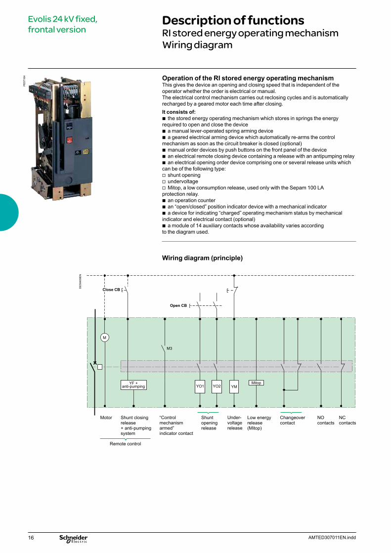
Operation of the RI stored energy operating mechanismThis gives the device an opening and closing speed that is independent of the operator whether the order is electrical or manual.The electrical control mechanism carries out reclosing cycles and is automatically recharged by a geared motor each time after closing. It consists of:
b the stored energy operating mechanism which stores in springs the energy required to open and close the device
b a manual lever-operated spring arming device b a geared electrical arming device which automatically re-arms the control
mechanism as soon as the circuit breaker is closed (optional) b manual order devices by push buttons on the front panel of the device b an electrical remote closing device containing a release with an antipumping relay b an electrical opening order device comprising one or several release units which
can be of the following type: v shunt opening v undervoltage v Mitop, a low consumption release, used only with the Sepam 100 LA
protection relay. b an operation counter b an “open/closed” position indicator device with a mechanical indicator b a device for indicating “charged” operating mechanism status by mechanical
indicator and electrical contact (optional) b a module of 14 auxiliary contacts whose availability varies according
to the diagram used.
Wiring diagram (principle)
M
YF +anti-pumping
Motor Shunt closingrelease+ anti-pumpingsystem
Remote control
Shunt openingrelease
Under-voltagerelease
Low energyrelease(Mitop)
NO contacts
Changeovercontact
NC contacts
Close CB
Open CB
YM
M3
Mitop
“Control mechanism armed” indicator contact
YO1 YO2
DE
5940
9EN
PE
5716
4
17AMTED307011EN.indd
Evolis 24 kV fixed, frontal version
Description of functionsOpening circuit
DE
5761
2EN
Operating mechanism
Shunt opening release (1)
Undervoltage release (2)
Low energy release (3)
(1) or (3)(2)
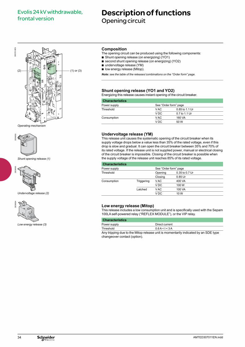
CompositionThe opening circuit can be produced using the following components:
b Shunt opening release (on energizing) (YO1) b second shunt opening release (on energizing) (YO2) b undervoltage release (YM) b low energy release (Mitop).
Note: see the table of the releases’combinations on the “Order form” page.
Shunt opening release (YO1 and YO2)Energizing this release causes instant opening of the circuit breaker.
CharacteristicsPower supply See “Order form” pageThreshold V AC 0.85 to 1.1 Ur
V DC 0.7 to 1.1 UrConsumption V AC 160 VA
V DC 50 W
Undervoltage release (YM)This release unit causes the systematic opening of the circuit breaker when itssupply voltage drops below a value less than 35% of the rated voltage, even if thisdrop is slow and gradual. It can open the circuit breaker between 35% and 70% ofits rated voltage. If the release unit is not supplied power, manual or electrical closingof the circuit breaker is impossible. Closing of the circuit breaker is possible whenthe supply voltage of the release unit reaches 85% of its rated voltage.
CharacteristicsPower supply See “Order form” pageThreshold Opening 0.35 to 0.7 Ur
Closing 0.85 UrConsumption Triggering V AC 400 VA
V DC 100 WLatched V AC 100 VA
V DC 10 W
Low energy release (Mitop)This release includes a low consumption unit and is specifically used with the Sepam 100LA self-powered relay (“REFLEX MODULE”), or the VIP relay.
CharacteristicsPower supply Direct current Threshold 0.6 A < I < 3 AAny tripping due to the Mitop release unit is momentarily indicated by an SDE type changeover contact (option).
DE
5809
2D
E58
093
DE
5809
4
18 AMTED307011EN.indd
Evolis 24 kV fixed, frontal version
Description of functionsRemote control
DE
5760
4
Operating mechanism
Electrical motor and gearing (4)
Shunt closing release (5)
Operation counter (6)
FunctionRemote control enables the remote opening and closing of the circuit breaker.
CompositionThe remote control mechanism comprises:
b an electrical motor with gearing b a shunt closing release (YF) combined with an anti-pumping device b an operation counter.
Electrical motor with gearing (M)The electrical motor carries out the automatic rearming of the stored energy unit as soon as the circuit breaker is closed. This allows the instant reclosing of the device after opening. The arming lever is only used as a backup operating mechanism in the case of the absence of the auxiliary power supply.The M3 contact indicates the end of arming operations.
CharacteristicsPower supply See “Order form” pageThreshold V AC/V DC 0.85 to 1.1 UrConsumption V AC 380 VA
V DC 380 W
Shunt closing release (YF)This release allows the remote closing of the circuit breaker when the operating mechanism is armed.
CharacteristicsPower supply See “Order form” pageThreshold V AC 0.85 to 1.1 Ur
V DC 0.85 to 1.1 UrConsumption V AC 160 VA
V DC 50 W
The shunt closing release is combined with an anti-pumping relay that enables priority to be given to opening in the case of a permanent closing order. This thus avoids the device being caught in an uncontrolled opening-closing cycle.
Operation counterThe operation counter is visible on the front panel.It displays the number of switching cycles (CO) that the device has carried out.
DE
5809
6D
E58
097
DE
5809
2
19AMTED307011EN.indd
Evolis 24 kV fixed, frontal version
Description of functionsIndication and locking/interlocking
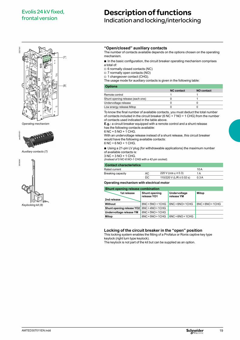
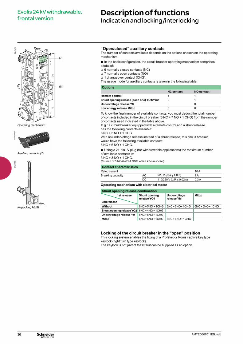
“Open/closed” auxiliary contacts The number of contacts available depends on the options chosen on the operating mechanism.
b In the basic configuration, the circuit breaker operating mechanism comprises a total of:
v 6 normally closed contacts (NC) v 7 normally open contacts (NO) v 1 changeover contact (CHG).
The usage mode for auxiliary contacts is given in the following table:
OptionsNC contact NO contact
Remote control 1 1Shunt opening release (each one) 0 1Undervoltage release 0 0Low energy release Mitop 0 0
To know the final number of available contacts, you must deduct the total number of contacts included in the circuit breaker (6 NC + 7 NO + 1 CHG) from the number of contacts used indicated in the table above.E.g.: a circuit breaker equipped with a remote control and a shunt release has the following contacts available:6 NC + 5 NO + 1 CHG. With an undervoltage release instead of a shunt release, this circuit breaker would have the following available contacts: 6 NC + 6 NO + 1 CHG.
b Using a 21-pin LV plug (for withdrawable applications) the maximum number of available contacts is:3 NC + 3 NO + 1 CHG.(Instead of 5 NC-6 NO-1 CHG with a 42-pin socket).
Contact characteristicsRated current 10 ABreaking capacity AC 220 V (cos j ≥ 0.3) 1 A
DC 110/220 V (L/R ≤ 0.02 s) 0.3 A
Operating mechanism with electrical motor
Shunt opening release combination1st release
2nd release
Shunt opening release YO1
Undervoltage release YM
Mitop
Without 6NC + 5NO + 1CHG 6NC + 6NO+ 1CHG 6NC + 6NO + 1CHGShunt opening release YO2 6NC + 4NO + 1CHGUndervoltage release YM 6NC + 5NO + 1CHGMitop 6NC + 5NO + 1CHG 6NC + 6NO + 1CHG
Locking of the circuit breaker in the “open” positionThis locking system enables the fitting of a Profalux or Ronis captive key type keylock (right turn type keylock). The keylock is not part of the kit but can be supplied as an option.
Operating mechanism
Auxiliary contacts (7)
Keylocking kit (8)
DE
5749
1D
E58
099
aav8
5914
01
20 AMTED307011EN.indd
Evolis 24 kV fixed, frontal version
Dimensions
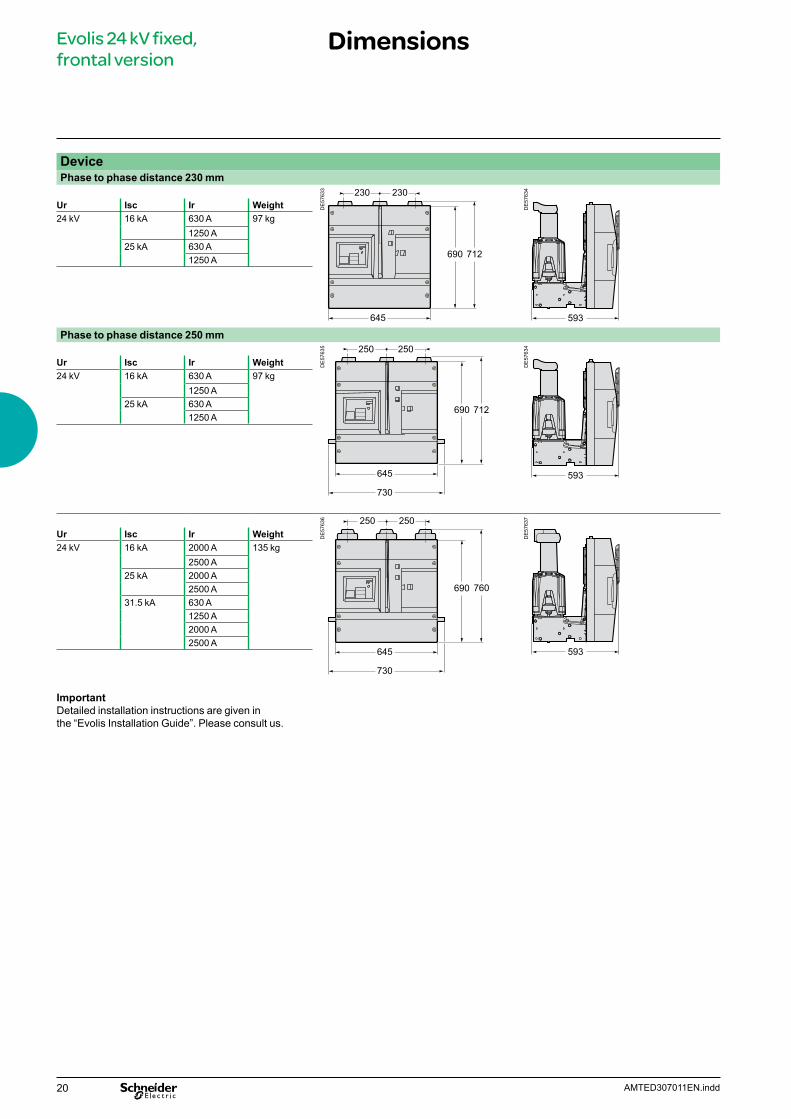
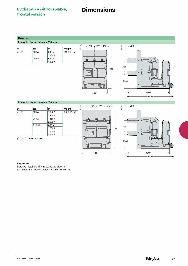
DevicePhase to phase distance 230 mm
DE
5763
3
DE
5763
4
593
Ur Isc Ir Weight24 kV 16 kA 630 A 97 kg
1250 A25 kA 630 A
1250 A
Phase to phase distance 250 mmD
E57
635
DE
5763
4
593
Ur Isc Ir Weight24 kV 16 kA 630 A 97 kg
1250 A25 kA 630 A
1250 A
DE
5763
6
DE
5763
7
593
Ur Isc Ir Weight24 kV 16 kA 2000 A 135 kg
2500 A25 kA 2000 A
2500 A 31.5 kA 630 A
1250 A2000 A2500 A
Important Detailed installation instructions are given in the “Evolis Installation Guide”. Please consult us.

21AMTED307011EN.indd
Releases combinations tableNo LV plug or 42-pin LV plug
21-pin LV plug
YO1 1 1 1 1 1YO2 1YM 1 1 1Mitop 1 1
Evolis 24 kV fixed, frontal version
Order form
Only one of the boxes (ticked X or filled by the needed value) have to be considered between each horizontal line. Green box X corresponds to none priced functions.
Basic fixed, frontal circuit breaker Quantity
Rated voltage Ur (kV) 24
Short circuit current Isc (kA)
Rated current Ir (A)
Phase to phase distance (mm) 230 250
Frequency 50 Hz 60 Hz Colour for push buttons and indicators
Push buttons open/closed: Red/black Indicator open/closed: Black/white Green/red Operating mechanism charged/discharged: White/yellow Charged/discharged
Circuit breaker optionsOpening release (see possible choices in combination table)
Shunt opening release YO124 Vdc 110 Vdc 220 Vdc 110 Vac (50 Hz) 48 Vdc 125 Vdc 220 Vac (50 Hz) 120 Vac (60 Hz)
Shunt opening release YO224 Vdc 110 Vdc 220 Vdc 110 Vac (50 Hz) 48 Vdc 125 Vdc 220 Vac (50 Hz) 120 Vac (60 Hz)
Undervoltage release YM24 Vdc 110 Vdc 220 Vdc 110 Vac (50 Hz) 48 Vdc 125 Vdc 220 Vac (50 Hz) 120 Vac (60 Hz)
Low energy release Mitop Without contact With contact
Remote control (operation counter already included)Electrical motor M 24…32 Vdc 110…127 Vdc/ac
48…60 Vdc/ac 220…250 Vdc/ac Shunt closing release YF
24 Vdc 110 Vdc 220 Vdc 110 Vac (50 Hz) 48 Vdc 125 Vdc 220 Vac (50 Hz) 120 Vac (60 Hz)
Operation counter (already included if remote control supplied) LV plug 21 pins 42 pins Locking of the circuit breaker in the open position
Locks and keys Profalux Ronis

22 AMTED307011EN.indd
Evolis 24 kV fixed, frontal version
Offer structureSeparated components
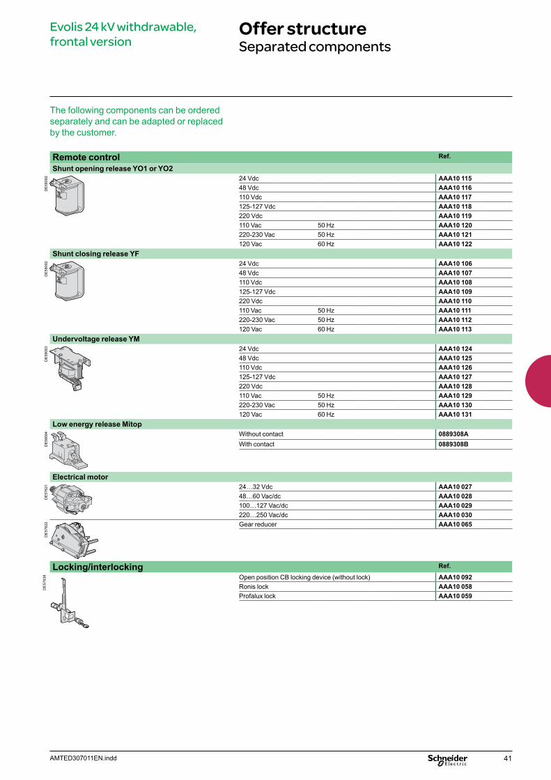
The following components can be ordered separately and can be adapted or replaced by the customer.
Remote control Ref.
Shunt opening release YO1 or YO2
DE
5809
2 24 Vdc AAA10 11548 Vdc AAA10 116110 Vdc AAA10 117125-127 Vdc AAA10 118220 Vdc AAA10 119110 Vac 50 Hz AAA10 120220-230 Vac 50 Hz AAA10 121120 Vac 60 Hz AAA10 122
Shunt closing release YF
DE
5809
2 24 Vdc AAA10 10648 Vdc AAA10 107110 Vdc AAA10 108125-127 Vdc AAA10 109220 Vdc AAA10 110110 Vac 50 Hz AAA10 111220-230 Vac 50 Hz AAA10 112120 Vac 60 Hz AAA10 113
Undervoltage release YM
DE
5809
3 24 Vdc AAA10 12448 Vdc AAA10 125110 Vdc AAA10 126125-127 Vdc AAA10 127220 Vdc AAA10 128110 Vac 50 Hz AAA10 129220-230 Vac 50 Hz AAA10 130120 Vac 60 Hz AAA10 131
Low energy release Mitop
DE
5809
4 Without contact 0889308AWith contact 0889308B
Electrical motor
DE
5762
1 24…32 Vdc AAA10 02748…60 Vac/dc AAA10 028100…127 Vac/dc AAA10 029220…250 Vac/dc AAA10 030
DE
5762
2 Gear reducer AAA10 065
Locking/interlocking Ref.
DE
5763
8 Open position CB locking (without lock) AAA10 092Ronis lock AAA10 058Profalux lock AAA10 059Interlocking kit fixed CB AAA10 033
23AMTED307011EN.indd
Evolis 24 kV fixed, frontal version
Offer structureSeparated components (cont.)
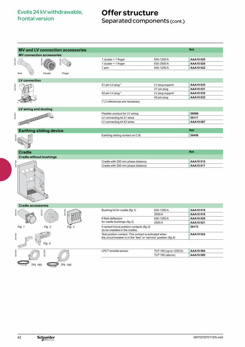
MV and LV connection accessories Ref.
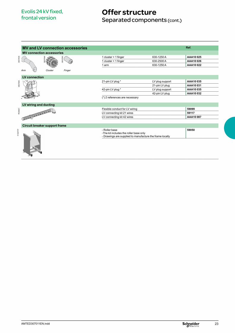
MV connection accessories
DE
5763
9
DE
5754
9
DE
5755
0
Cluster FingerArm
1 cluster + 1 finger 630-1250 A AAA10 0251 cluster + 1 finger 630-2500 A AAA10 0261 arm 630-1250 A AAA10 022
LV connection
DE
5764
0 21-pin LV plug * LV plug support AAA10 03521-pin LV plug AAA10 031
42-pin LV plug * LV plug support AAA10 03542-pin LV plug AAA10 032
(*) 2 references are necessary
LV wiring and ducting
PE
5660
1 Flexible conduct for LV wiring 59099LV connecting kit 21 wires 59117LV connecting kit 42 wires AAA10 087
Circuit breaker support frame
5122
2737 - Roller base
-The kit includes the roller base only- Drawings are supplied to manufacture the frame locally
59050
24 AMTED307011EN.indd
Evolis 24 kV fixed, frontal version
Services
The following components can only be adapted or replaced on site by staff trained by Schneider Electric
b Remote control mechanism (comprising: electrical motor, gearing, shunt closing release, anti-pumping relay, operation counter)
b Operation counter b Low energy release (Mitop) b Circuit breaker front cover.
25AMTED307011EN.indd
Evolis 24 kV withdrawable, frontal version
Contents
Presentation 26Main characteristics 27Description of functions 28Racking in 28LPCT sensors 30 MV connection 31LV connection 32RI stored energy operating mechanism 33Wiring diagram 33Opening circuit 34Remote control 35Indication and locking/interlocking 36Safety functions 37Service trucks 38
Dimensions 39Order form 40Offer structure 41Separated components 41
Services 44
26 AMTED307011EN.indd
Evolis 24 kV withdrawable, frontal version
Presentation
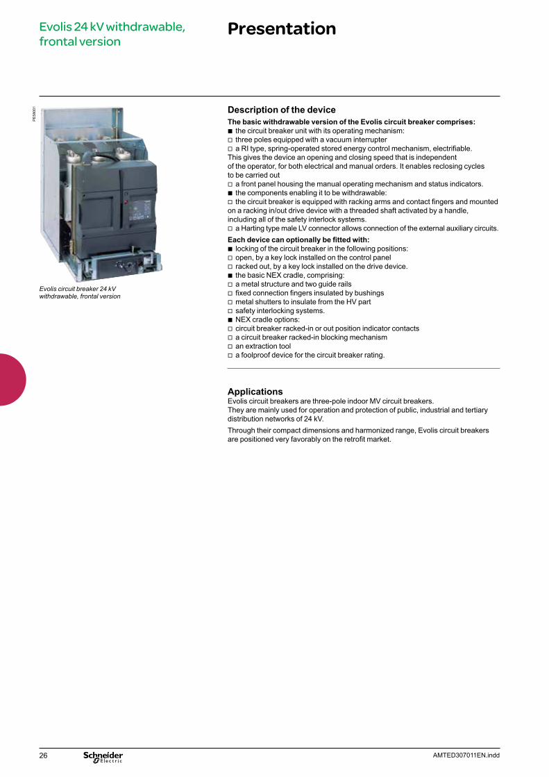
Description of the deviceThe basic withdrawable version of the Evolis circuit breaker comprises:
b the circuit breaker unit with its operating mechanism: v three poles equipped with a vacuum interrupter v a RI type, spring-operated stored energy control mechanism, electrifiable.
This gives the device an opening and closing speed that is independent of the operator, for both electrical and manual orders. It enables reclosing cycles to be carried out
v a front panel housing the manual operating mechanism and status indicators. b the components enabling it to be withdrawable: v the circuit breaker is equipped with racking arms and contact fingers and mounted
on a racking in/out drive device with a threaded shaft activated by a handle, including all of the safety interlock systems.
v a Harting type male LV connector allows connection of the external auxiliary circuits.Each device can optionally be fitted with:
b locking of the circuit breaker in the following positions: v open, by a key lock installed on the control panel v racked out, by a key lock installed on the drive device. b the basic NEX cradle, comprising: v a metal structure and two guide rails v fixed connection fingers insulated by bushings v metal shutters to insulate from the HV part v safety interlocking systems. b NEX cradle options: v circuit breaker racked-in or out position indicator contacts v a circuit breaker racked-in blocking mechanism v an extraction tool v a foolproof device for the circuit breaker rating.
Applications Evolis circuit breakers are three-pole indoor MV circuit breakers. They are mainly used for operation and protection of public, industrial and tertiary distribution networks of 24 kV. Through their compact dimensions and harmonized range, Evolis circuit breakers are positioned very favorably on the retrofit market.
PE
5800
1
Evolis circuit breaker 24 kV withdrawable, frontal version
27AMTED307011EN.indd
Evolis 24 kV withdrawable, frontal version
Main characteristics
Electrical characteristics according to IEC 62271-100Phase to phase 230 250
Rated voltage Ur kV 50/60 Hz 24 24Insulation level- power frequency withstand Ud kV 50 Hz 1 min 50 50- lightning impulse withstand Up kV peak 125 125Rated current Ir A 630 b b – – b
1250 b b – – b
2000 – – b b b
2500 – – b b b
Short circuit current Isc kA 16 25 16 25 31.5Short time withstand current Ik/tk kA/3 s 16 25 16 25 31.5Short-circuit making current Ip kA peak 50 Hz 40 63 40 63 79
60 Hz 42 65 42 65 82
Common characteristics according to IEC 62271-100Rated switching sequence O-3 min-CO-3 min-CO b
O-0.3 s-CO-3 min-CO b
O-0.3 s-CO-15 s-CO b
Operating times Opening ms < 50Breaking ms < 65Closing ms < 85
Mechanical endurance Class M2Number of switching operations
10 000
Electrical endurance Class E2Number of switching operations at full Isc value
16 kA 10025 kA 10031.5 kA 100
Capacitive current breaking capacity Class C1-C2 (for certain applications)
Service temperature – 25°C to 40°CAverage relative humidity over 24 h < 95%
over 1 month < 90%
b Available– Not available
28 AMTED307011EN.indd
Evolis 24 kV withdrawable, frontal version
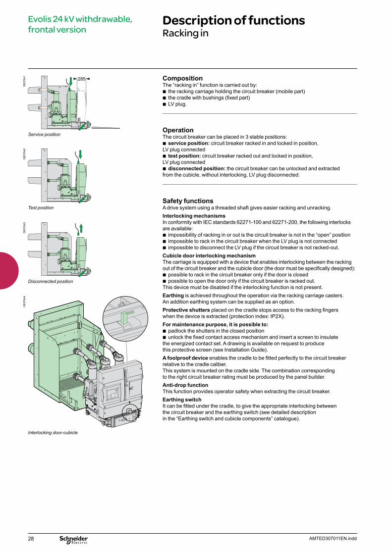
Description of functionsRacking in
DE
5764
1 CompositionThe “racking in” function is carried out by:
b the racking carriage holding the circuit breaker (mobile part) b the cradle with bushings (fixed part) b LV plug.
OperationThe circuit breaker can be placed in 3 stable positions:
b service position: circuit breaker racked in and locked in position, LV plug connected
b test position: circuit breaker racked out and locked in position, LV plug connected
b disconnected position: the circuit breaker can be unlocked and extracted from the cubicle, without interlocking, LV plug disconnected.
Safety functionsA drive system using a threaded shaft gives easier racking and unracking. Interlocking mechanismsIn conformity with IEC standards 62271-100 and 62271-200, the following interlocks are available:
b impossibility of racking in or out is the circuit breaker is not in the “open” position b impossible to rack in the circuit breaker when the LV plug is not connected b impossible to disconnect the LV plug if the circuit breaker is not racked-out.
Cubicle door interlocking mechanismThe carriage is equipped with a device that enables interlocking between the racking out of the circuit breaker and the cubicle door (the door must be specifically designed):
b possible to rack in the circuit breaker only if the door is closed b possible to open the door only if the circuit breaker is racked out.
This device must be disabled if the interlocking function is not present.Earthing is achieved throughout the operation via the racking carriage casters. An addition earthing system can be supplied as an option.Protective shutters placed on the cradle stops access to the racking fingers when the device is extracted (protection index: IP2X).For maintenance purpose, it is possible to:
b padlock the shutters in the closed position b unlock the fixed contact access mechanism and insert a screen to insulate
the energized contact set. A drawing is available on request to produce this protective screen (see Installation Guide).A foolproof device enables the cradle to be fitted perfectly to the circuit breaker relative to the cradle caliber. This system is mounted on the cradle side. The combination corresponding to the right circuit breaker rating must be produced by the panel builder.Anti-drop functionThis function provides operator safety when extracting the circuit breaker. Earthing switchIt can be fitted under the cradle, to give the appropriate interlocking between the circuit breaker and the earthing switch (see detailed description in the “Earthing switch and cubicle components” catalogue).
Service position
DE
5764
2
Test position
DE
5764
3
Disconnected position
DE
5764
4
Interlocking door-cubicle
29AMTED307011EN.indd
Evolis 24 kV withdrawable, frontal version
Description of functionsRacking in (cont.)
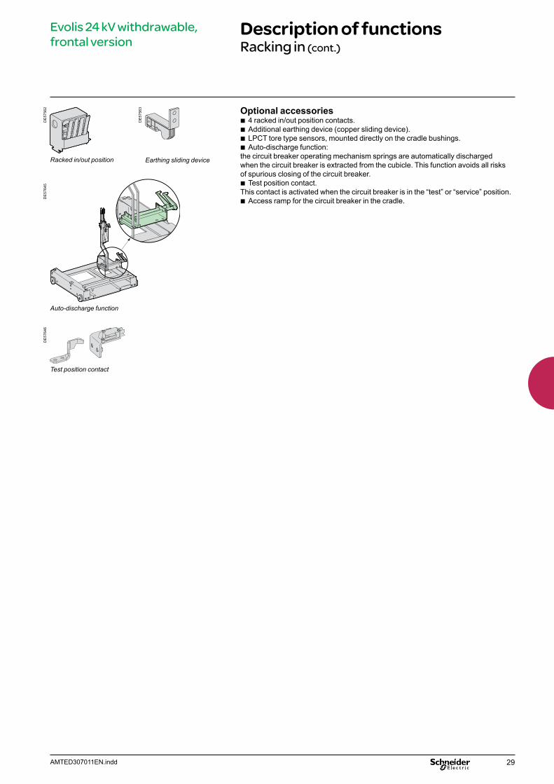
Optional accessories b 4 racked in/out position contacts. b Additional earthing device (copper sliding device). b LPCT tore type sensors, mounted directly on the cradle bushings. b Auto-discharge function:
the circuit breaker operating mechanism springs are automatically discharged when the circuit breaker is extracted from the cubicle. This function avoids all risks of spurious closing of the circuit breaker.
b Test position contact.This contact is activated when the circuit breaker is in the “test” or “service” position.
b Access ramp for the circuit breaker in the cradle.
DE
5764
6D
E57
645
Auto-discharge function
DE
5756
3
Racked in/out position Earthing sliding device
DE
5756
2
Test position contact

30 AMTED307011EN.indd
Evolis 24 kV withdrawable, frontal version
Description of functionsLPCT sensors
LPCT sensors are the best way to increase the effectiveness of the protection chain and simplify the selection.
FunctionLPCT type sensors (Low Power Current Transducers) provide accurate measurement for protection functions when an Evolis circuit breaker is combined with a Sepam range relay.They comply with IEC 60044-8 standard.
CompositionTwo types of LPCT are available:
b LPCT’s for bushings, with LV insulation for cradle installation (TLP type) b LPCT with MV insulation for cubicle installation (CLP type).
The sensor is supplied with 5 m of cable and connectors that allowsdirect connection to the Sepam unit.
Mechanical characteristics (LPCT for bushings TLP type)Mounted directly on the Evolis withdrawable circuit breaker cradle. The sensors are simply located on the bushings and fixed using three screws.Each sensor covers the full operating range of the corresponding circuit breaker.Connection to the Sepam is achieved using a shielded cable which is attached toeach sensor.
Electrical characteristics: b conformity with IEC standard 60044-8, which defines LPCT’s with an output voltage b usable for nominal currents of 25 A to 2500 A b class 0.5 throughout the range b current sensors give a voltage output at a ratio of 100 A/22.5 mV.
Common featuresRated primary current 100 ARated secondary output (at 100 A) 22.5 mVAccuracy class for measuring 0.5Accuracy class for protection 5PBurden u 2 kWFrequency 50/60 Hz
Specific features CLP2 CLP3 TLP160 TLP190Assembly In the cubicle In the cubicle On the bushings On the bushings
DE
5810
4
DE
5810
5
DE
5810
6
DE
5810
7
Rated extended primary current 1250 A 2500 A 1250 A 2500 AAccuracy limit factor 250 315 250 315Rated short time thermal current 25 kA/3 s 31.5 kA/3 s 25 kA/3 s 31.5 kA/3 sRated voltage 24 kV 24 kV 24 kV (1) 24 kV (1)
Rated power frequency withstand voltage 50 kV 50 kV 50 kV 50 kVRated lightning impulse withstand voltage 125 kV 125 kV 125 kV 125 kVInternal diameter 160 mm 190 mm
(1) Voltage applied to the cradle equipped with sensors.
LPCT for bushings (TLP type)
LPCT for cubicle (CLP type)
DE
5810
6D
E58
104
31AMTED307011EN.indd
Evolis 24 kV withdrawable, frontal version
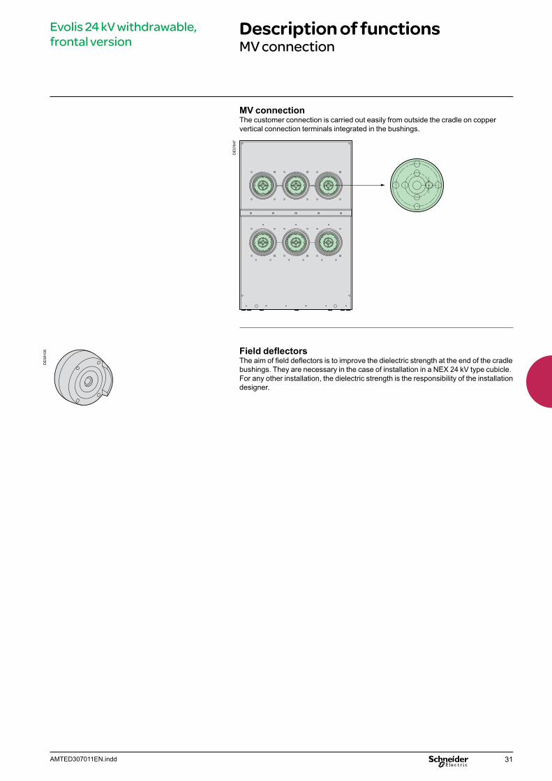
Description of functionsMV connection
MV connectionThe customer connection is carried out easily from outside the cradle on copper vertical connection terminals integrated in the bushings.
DE5
7647
Field deflectorsThe aim of field deflectors is to improve the dielectric strength at the end of the cradle bushings. They are necessary in the case of installation in a NEX 24 kV type cubicle. For any other installation, the dielectric strength is the responsibility of the installation designer.
DE
5810
8

32 AMTED307011EN.indd
Evolis 24 kV withdrawable, frontal version
Description of functionsLV connection
DE
5764
8
Push ON
Push OFF
Main functionsWith the base circuit breaker, the LV wiring uses a LV plug unit which comprises:
b the fixed part (male) mounted on the circuit breaker and fully connected to the control mechanism
b the mobile part (female) compatible with the male part.
Two versions of the LV plug are availableAn 21-pin version, enabling connection of:
b a shunt opening release YO1 b an electrical remote control mechanism (electrical motor, shunt closing release YF,
anti-pumping relay) b a maximum number of auxiliary contacts: 3 NC - 3 NO - 1 changeover contact.
(see “indication and locking/interlocking” page, “Open/closed position auxiliary contacts” chapter).Note: see the table of the releases’ combinations “Order form” page.
An 42-pin version, enabling connection of: b an opening release (shunt type YO1 or undervoltage type YM) b a second opening release (shunt type YO2 or undervoltage type YM
or Mitop low energy release) b an electrical remote control mechanism (electrical motor, shunt closing release YF,
anti-pumping relay) b a maximum number of auxiliary contacts: 5 NC -6 NO -1 changeover contact.
(see “indication and locking/interlocking” page, “Open/closed position auxiliary contacts” chapter).Note: see the table of the releases’ combinations “Order form” page.
Interlocking function In conformity with IEC standard 62271-200, an interlocking function prohibits:
b racking in when the LV plug is not connected b disconnection of the LV plug if the circuit breaker is in the racked-in position.
LV wiring kitA wiring kit with 21 or 42 wires (2 meters long) equipped with pins that can be adapted to the LV plug can be supplied for connected in to the cubicle’s LV compartment.
Flexible ductingThis 525 mm long duct with a hinged LV plug, enables protection of the LV wiring that connects the circuit breaker to the cubicle’s LV compartment.

33AMTED307011EN.indd
Evolis 24 kV withdrawable, frontal version
Description of functionsRI stored energy operating mechanismWiring diagram
Operation of the RI stored energy operating mechanismThis gives the device an opening and closing speed that is independent of the operator whether the order is electrical or manual.The electrical control mechanism carries out reclosing cycles and is automatically recharged by a geared motor each time after closing. It consists of:
b the stored energy operating mechanism which stores in springs the energy required to open and close the device
b a manual lever-operated spring arming device b a geared electrical arming device which automatically re-arms the control
mechanism as soon as the circuit breaker is closed (optional) b manual order devices by push buttons on the front panel of the device b an electrical remote closing device containing a release with an antipumping relay b an electrical opening order device comprising one or several release units which
can be of the following type: v shunt opening v undervoltage v Mitop, a low consumption release, used only with the Sepam 100 LA
protection relay. b an operation counter b an “open/closed” position indicator device with a mechanical indicator b a device for indicating “charged” operating mechanism status by mechanical
indicator and electrical contact (optional) b a module of 14 auxiliary contacts whose availability varies according
to the diagram used.
Wiring diagram (principle)
M
YF +anti-pumping
Motor Shunt closingrelease+ anti-pumpingsystem
Remote control
Shunt openingrelease
Under-voltagerelease
Low energyrelease(Mitop)
NO contacts
Changeovercontact
NC contacts
Close CB
Open CB
YM
M3
Mitop
“Control mechanism armed” indicator contact
YO1 YO2
DE
5940
9EN
PE
5716
4
34 AMTED307011EN.indd
Evolis 24 kV withdrawable, frontal version
Description of functionsOpening circuit
DE
5761
2EN
Operating mechanism
Shunt opening release (1)
Undervoltage release (2)
Low energy release (3)
(1) or (3)(2)
CompositionThe opening circuit can be produced using the following components:
b Shunt opening release (on energizing) (YO1) b second shunt opening release (on energizing) (YO2) b undervoltage release (YM) b low energy release (Mitop).
Note: see the table of the releases’combinations on the “Order form” page.
Shunt opening release (YO1 and YO2)Energizing this release causes instant opening of the circuit breaker.
CharacteristicsPower supply See “Order form” pageThreshold V AC 0.85 to 1.1 Ur
V DC 0.7 to 1.1 UrConsumption V AC 160 VA
V DC 50 W
Undervoltage release (YM)This release unit causes the systematic opening of the circuit breaker when itssupply voltage drops below a value less than 35% of the rated voltage, even if thisdrop is slow and gradual. It can open the circuit breaker between 35% and 70% ofits rated voltage. If the release unit is not supplied power, manual or electrical closingof the circuit breaker is impossible. Closing of the circuit breaker is possible whenthe supply voltage of the release unit reaches 85% of its rated voltage.
CharacteristicsPower supply See “Order form” pageThreshold Opening 0.35 to 0.7 Ur
Closing 0.85 UrConsumption Triggering V AC 400 VA
V DC 100 WLatched V AC 100 VA
V DC 10 W
Low energy release (Mitop)This release includes a low consumption unit and is specifically used with the Sepam 100LA self-powered relay (“REFLEX MODULE”), or the VIP relay.
CharacteristicsPower supply Direct current Threshold 0.6 A < I < 3 AAny tripping due to the Mitop release unit is momentarily indicated by an SDE type changeover contact (option).
DE
5809
2D
E58
093
DE
5809
4
35AMTED307011EN.indd
Evolis 24 kV withdrawable, frontal version
Description of functionsRemote control
DE
5760
4
Operating mechanism
Electrical motor and gearing (4)
Shunt closing release (5)
Operation counter (6)
FunctionRemote control enables the remote opening and closing of the circuit breaker.
CompositionThe remote control mechanism comprises:
b an electrical motor with gearing b a shunt closing release (YF) combined with an anti-pumping device b an operation counter.
Electrical motor with gearing (M)The electrical motor carries out the automatic rearming of the stored energy unit as soon as the circuit breaker is closed. This allows the instant reclosing of the device after opening. The arming lever is only used as a backup operating mechanism in the case of the absence of the auxiliary power supply.The M3 contact indicates the end of arming operations.
CharacteristicsPower supply See “Order form” pageThreshold V AC/V DC 0.85 to 1.1 UrConsumption V AC 380 VA
V DC 380 W
Shunt closing release (YF)This release allows the remote closing of the circuit breaker when the operating mechanism is armed.
CharacteristicsPower supply See “Order form” pageThreshold V AC 0.85 to 1.1 Ur
V DC 0.85 to 1.1 UrConsumption V AC 160 VA
V DC 50 W
The shunt closing release is combined with an anti-pumping relay that enables priority to be given to opening in the case of a permanent closing order. This thus avoids the device being caught in an uncontrolled opening-closing cycle.
Operation counterThe operation counter is visible on the front panel.It displays the number of switching cycles (CO) that the device has carried out.
DE
5809
6D
E58
097
DE
5809
2
36 AMTED307011EN.indd
Evolis 24 kV withdrawable, frontal version
Description of functionsIndication and locking/interlocking
Operating mechanism
Auxiliary contacts (7)
Keylocking kit (8)
DE
5749
1D
E58
099
“Open/closed” auxiliary contacts The number of contacts available depends on the options chosen on the operating mechanism.
b In the basic configuration, the circuit breaker operating mechanism comprises a total of:
v 6 normally closed contacts (NC) v 7 normally open contacts (NO) v 1 changeover contact (CHG).
The usage mode for auxiliary contacts is given in the following table:
OptionsNC contact NO contact
Remote control 1 1Shunt opening release (each one) YO1/YO2 0 1Undervoltage release YM 0 0Low energy release Mitop 0 0
To know the final number of available contacts, you must deduct the total number of contacts included in the circuit breaker (6 NC + 7 NO + 1 CHG) from the number of contacts used indicated in the table above.E.g.: a circuit breaker equipped with a remote control and a shunt release has the following contacts available:6 NC + 5 NO + 1 CHG. With an undervoltage release instead of a shunt release, this circuit breaker would have the following available contacts: 6 NC + 6 NO + 1 CHG.
b Using a 21-pin LV plug (for withdrawable applications) the maximum number of available contacts is:3 NC + 3 NO + 1 CHG.(Instead of 5 NC-6 NO-1 CHG with a 42-pin socket).
Contact characteristicsRated current 10 ABreaking capacity AC 220 V (cos j ≥ 0.3) 1 A
DC 110/220 V (L/R ≤ 0.02 s) 0.3 A
Operating mechanism with electrical motor
Shunt opening release combination1st release
2nd release
Shunt opening release YO1
Undervoltage release YM
Mitop
Without 6NC + 5NO + 1CHG 6NC + 6NO+ 1CHG 6NC + 6NO + 1CHGShunt opening release YO2 6NC + 4NO + 1CHGUndervoltage release YM 6NC + 5NO + 1CHGMitop 6NC + 5NO + 1CHG 6NC + 6NO + 1CHG
Locking of the circuit breaker in the “open” positionThis locking system enables the fitting of a Profalux or Ronis captive key type keylock (right turn type keylock). The keylock is not part of the kit but can be supplied as an option.
aav8
5914
01

37AMTED307011EN.indd
Evolis 24 kV withdrawable, frontal version
Description of functionsSafety functions
Parts Circuit breaker positionsInsertion
Extraction
Racking-in
Racking-out
Removed Disconnected Test position Service
1 - Cradle Fool-proof protection (1)
Anti-drop (2)
No opening shutters
Shutters padlocking possible
2 - LV plug Disconnected No racking-in
Connected No unplugging
3 - Circuit breaker Closed No racking-in No racking-out
Open No closing
Open position circuit breaker locking available (3)
4 - Switchboard door Open No racking-in
Closed No door opening (4)
5 - Earthing switch Open No earthing switch closing
Closed No racking-in
(1) This protection mechanism ensures that the performance levels of the circuit breaker correspond with those of the cradle.(2) Device that prevents the circuit breaker from dropping when extracted from the cradle. The device can be either unlocked manually or when the extraction rig is put in position.(3) Option.(4) Interlocking device to be fitted to the cubicle door. If there is no interlocking, the circuit breaker device should be inhibited.
This table describes the safety functions available on the withdrawable version of the Evolis 24 kV circuit breaker.How to use the tableEach of the boxes describes the functional status of each circuit breaker position and the associated parts:
Possible status
Possible status, impossible operation
Impossible status
38 AMTED307011EN.indd
Evolis 24 kV withdrawable, frontal version
Description of functionsService trucks
DE
5757
2D
E57
573
Earthing truck
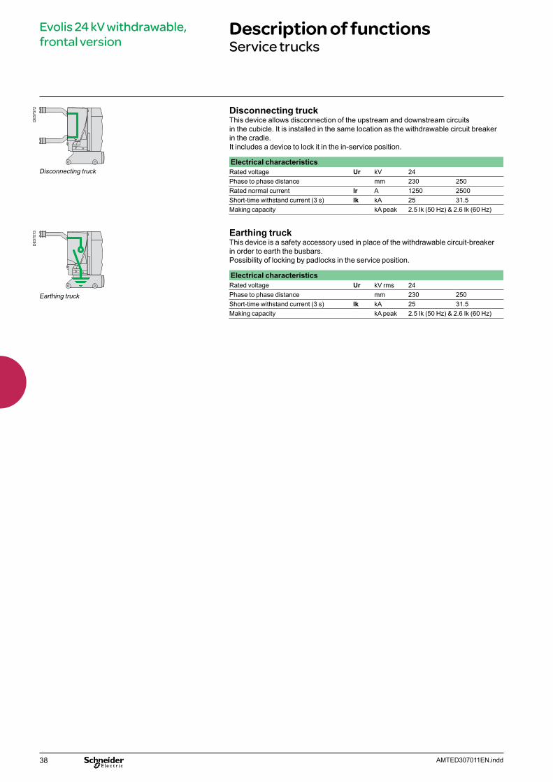
Disconnecting truck
Disconnecting truckThis device allows disconnection of the upstream and downstream circuits in the cubicle. It is installed in the same location as the withdrawable circuit breaker in the cradle.It includes a device to lock it in the in-service position.
Electrical characteristicsRated voltage Ur kV 24Phase to phase distance mm 230 250Rated normal current Ir A 1250 2500Short-time withstand current (3 s) Ik kA 25 31.5Making capacity kA peak 2.5 Ik (50 Hz) & 2.6 Ik (60 Hz)
Earthing truckThis device is a safety accessory used in place of the withdrawable circuit-breaker in order to earth the busbars.Possibility of locking by padlocks in the service position.
Electrical characteristicsRated voltage Ur kV rms 24Phase to phase distance mm 230 250Short-time withstand current (3 s) Ik kA 25 31.5Making capacity kA peak 2.5 Ik (50 Hz) & 2.6 Ik (60 Hz)
39AMTED307011EN.indd
Evolis 24 kV withdrawable, frontal version
Dimensions
DevicePhase to phase distance 230 mm
DE
5765
3
1188
230 230 163
786
DE
5765
4
14001309
288
400
473.5
Ur Isc Ir Weight *24 kV 16 kA 630 A 145 + 125 kg
1250 A25 kA 630 A
1250 A
Phase to phase distance 250 mm
DE
5765
5 250 250 193
1188
886
DE
5765
4
14001309
288
400
473.5
Ur Isc Ir Weight *24 kV 16 kA 1250 A 206 + 148 kg
2500 A25 kA 1250 A
2500 A31.5 kA 630 A
1250 A2000 A2500 A
(*) Circuit breaker + cradle
Important Detailed installation instructions are given in the “Evolis Installation Guide”. Please consult us.

40 AMTED307011EN.indd
Evolis 24 kV withdrawable, frontal version
Order form
Only one of the boxes (ticked X or filled by the needed value) have to be considered between each horizontal line. Green box X corresponds to none priced functions.
Releases combinations tableNo LV plug or 42-pin LV plug
21-pin LV plug
YO1 1 1 1 1 1YO2 1YM 1 1 1Mitop 1 1
Basic withdrawable, frontal circuit breaker Quantity
Rated voltage Ur (kV) 24
Short circuit current Isc (kA)
Rated current Ir (A)
Phase to phase distance (mm) 230 250
Frequency 50 Hz 60 Hz Colour for push buttons and indicators
Push buttons open/closed: Red/black Indicator open/closed: Black/white Green/red Operating mechanism charged/discharged: White/yellow Charged/discharged
Circuit breaker optionsOpening release (see possible choices in combination table)
Shunt opening release YO124 Vdc 110 Vdc 220 Vdc 110 Vac (50 Hz) 48 Vdc 125 Vdc 220 Vac (50 Hz) 120 Vac (60 Hz)
Shunt opening release YO224 Vdc 110 Vdc 220 Vdc 110 Vac (50 Hz) 48 Vdc 125 Vdc 220 Vac (50 Hz) 120 Vac (60 Hz)
Undervoltage release YM24 Vdc 110 Vdc 220 Vdc 110 Vac (50 Hz) 48 Vdc 125 Vdc 220 Vac (50 Hz) 120 Vac (60 Hz)
Low energy release Mitop Without contact With contact
Remote control (operation counter already included)Electrical motor M 24…32 Vdc 110…127 Vdc/ac
48…60 Vdc/ac 220…250 Vdc/ac Shunt closing release YF
24 Vdc 110 Vdc 220 Vdc 110 Vac (50 Hz) 48 Vdc 125 Vdc 220 Vac (50 Hz) 120 Vac (60 Hz)
Operation counter (already included if remote control supplied) LV plug 42 pins (instead of 21) Operating shaft Open position CB locking device (without lock) Locking of the circuit breaker in the open position
Locks and keys Profalux Ronis Discharge of the circuit breaker control mechanism springs Earthing sliding contact
CradleRated current Up to 1250 A and 25 kA Above 1250 A or 25 kA
Cradle accessoriesRack in/rack out position contact (4 AC) LPCT-TLP Up to 1250 A and 25 kA Above 1250 A or 25 kA Test position contact This contact is activated when the circuit breaker is in the “test” or “service” position6 field deflectors 630-2500 A 2500 A
41AMTED307011EN.indd
Evolis 24 kV withdrawable, frontal version
Offer structureSeparated components
The following components can be ordered separately and can be adapted or replaced by the customer.
Remote control Ref.
Shunt opening release YO1 or YO2
DE
5809
2 24 Vdc AAA10 11548 Vdc AAA10 116110 Vdc AAA10 117125-127 Vdc AAA10 118220 Vdc AAA10 119110 Vac 50 Hz AAA10 120220-230 Vac 50 Hz AAA10 121120 Vac 60 Hz AAA10 122
Shunt closing release YF
DE
5809
2 24 Vdc AAA10 10648 Vdc AAA10 107110 Vdc AAA10 108125-127 Vdc AAA10 109220 Vdc AAA10 110110 Vac 50 Hz AAA10 111220-230 Vac 50 Hz AAA10 112120 Vac 60 Hz AAA10 113
Undervoltage release YM
DE
5809
3 24 Vdc AAA10 12448 Vdc AAA10 125110 Vdc AAA10 126125-127 Vdc AAA10 127220 Vdc AAA10 128110 Vac 50 Hz AAA10 129220-230 Vac 50 Hz AAA10 130120 Vac 60 Hz AAA10 131
Low energy release Mitop
DE
5809
4 Without contact 0889308AWith contact 0889308B
Electrical motor
DE
5762
1 24…32 Vdc AAA10 02748…60 Vac/dc AAA10 028100…127 Vac/dc AAA10 029220…250 Vac/dc AAA10 030
DE
5762
2 Gear reducer AAA10 065
Locking/interlocking Ref.
DE
5763
8 Open position CB locking device (without lock) AAA10 092Ronis lock AAA10 058Profalux lock AAA10 059
42 AMTED307011EN.indd
Evolis 24 kV withdrawable, frontal version
Offer structureSeparated components (cont.)
MV and LV connection accessories Ref.
MV connection accessories
DE
5763
9
DE
5754
9
DE
5755
0
Cluster FingerArm
1 cluster + 1 finger 630-1250 A AAA10 0251 cluster + 1 finger 630-2500 A AAA10 0261 arm 630-1250 A AAA10 022
LV connection
DE
5764
0 21-pin LV plug * LV plug support AAA10 03521-pin plug AAA10 031
42-pin LV plug * LV plug support AAA10 03542-pin plug AAA10 032
(*) 2 references are necessary
LV wiring and ducting
PE
5660
1 Flexible conduct for LV wiring 59099LV connecting kit 21 wires 59117LV connecting kit 42 wires AAA10 087
Earthing sliding device Ref.
DE
5756
3 Earthing sliding contact on C.B. 59456
Cradle Ref.
Cradle without bushings
DE
5765
6 Cradle with 230 mm phase distance AAA10 015Cradle with 250 mm phase distance AAA10 017
Cradle accessories
DE
5758
1
DE
5756
2
DE
5765
7
Fig. 1 Fig. 2 Fig. 3
Fig. 4
Bushing kit for cradle (fig.1) 630-1250 A AAA10 0162500 A AAA10 018
6 field deflectorsfor cradle bushings (fig.2)
630-1250 A AAA10 0202500 A AAA10 021
4 racked in/out position contacts (fig.3)(to be installed in the cradle)
59173
DE
5764
6 Test position contact. This contact is activated when the circuit breaker is in the “test” or “service” position (fig.4)
AAA10 024
DE
5765
8
DE
5765
9
TPL 160 TPL 190
LPCT toroidal sensor TLP 160 (up to 1250 A) AAA10 094TLP 190 (above) AAA10 095
43AMTED307011EN.indd
Evolis 24 kV withdrawable, frontal version
Offer structureSeparated components (cont.)
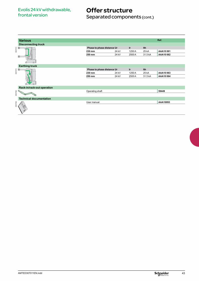
Various Ref.
Disconnecting truck
DE
5757
2 Phase to phase distance Ur Ir Ith230 mm 24 kV 1250 A 25 kA AAA10 061250 mm 24 kV 2500 A 31.5 kA AAA10 062
Earthing truck
DE
5757
3 Phase to phase distance Ur Ir Ith230 mm 24 kV 1250 A 25 kA AAA10 063250 mm 24 kV 2500 A 31.5 kA AAA10 064
Rack-in/rack-out operation
DE
5758
2 Operating shaft 59449
Technical documentation
DE
5755
6 User manual AAA10093

44 AMTED307011EN.indd
Evolis 24 kV withdrawable, frontal version
Services
The following components can only be adapted or replaced on site by staff trained by Schneider Electric
b Remote control mechanism (comprising: electrical motor, gearing, shunt closing release, anti-pumping relay, operation counter)
b Operation counter b Low energy release (Mitop) b Interlocking between the “open” circuit breaker position and the LV plug b Racking truck b Auto-discharge device b Circuit breaker front cover.

45AMTED307011EN.indd
Presentation 46Main characteristics 47Description of functions 48 MV and LV connection 48RI stored energy operating mechanism 49Wiring diagram 49Opening circuit 50Remote control 51Indication and locking/interlocking 52
Dimensions 53Order form 54Offer structure 55Separated components 55
Services 56
Evolis 24 kV fixed, lateral version
Contents
46 AMTED307011EN.indd
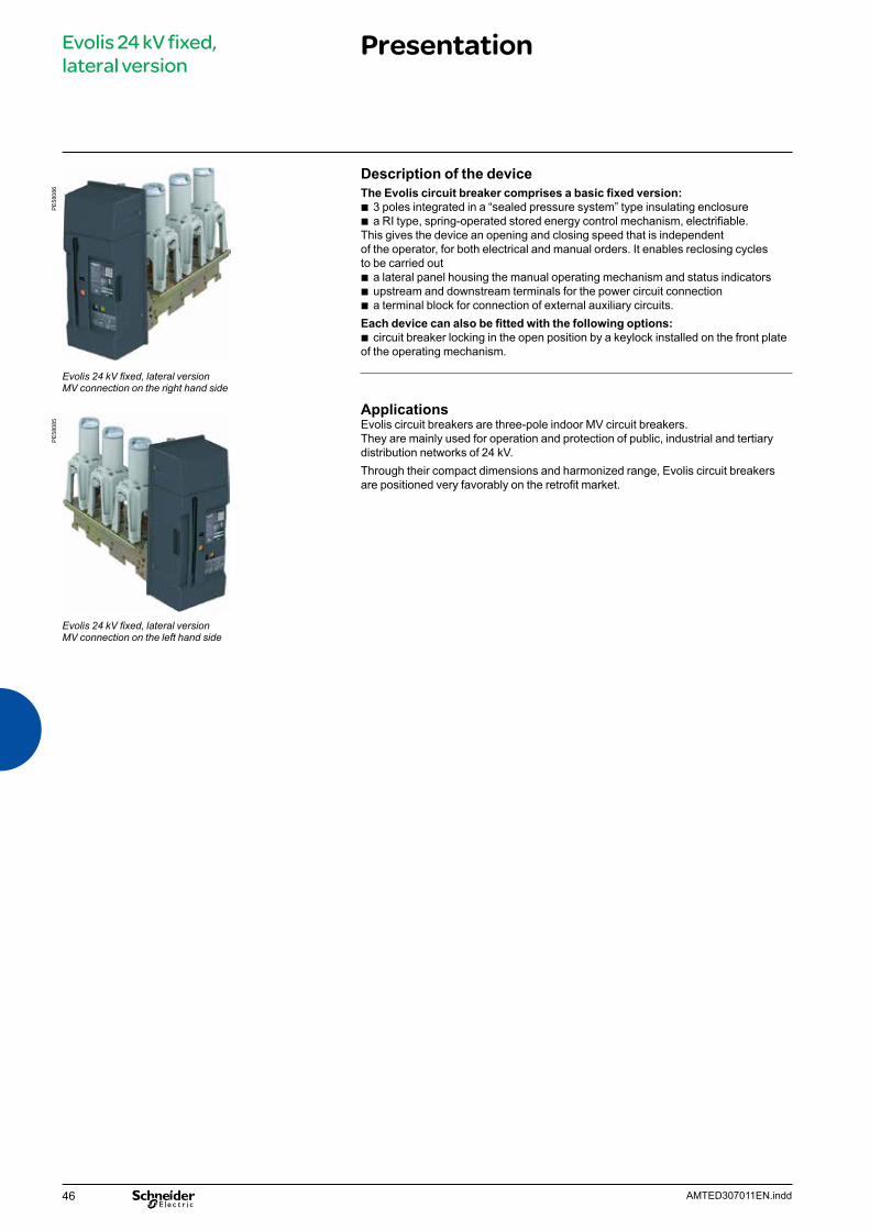
Description of the device The Evolis circuit breaker comprises a basic fixed version:
b 3 poles integrated in a “sealed pressure system” type insulating enclosure b a RI type, spring-operated stored energy control mechanism, electrifiable.
This gives the device an opening and closing speed that is independent of the operator, for both electrical and manual orders. It enables reclosing cycles to be carried out
b a lateral panel housing the manual operating mechanism and status indicators b upstream and downstream terminals for the power circuit connection b a terminal block for connection of external auxiliary circuits.
Each device can also be fitted with the following options: b circuit breaker locking in the open position by a keylock installed on the front plate
of the operating mechanism.
Applications Evolis circuit breakers are three-pole indoor MV circuit breakers. They are mainly used for operation and protection of public, industrial and tertiary distribution networks of 24 kV. Through their compact dimensions and harmonized range, Evolis circuit breakers are positioned very favorably on the retrofit market.
Evolis 24 kV fixed, lateral versionMV connection on the right hand side
Evolis 24 kV fixed, lateral version
Presentation
Evolis 24 kV fixed, lateral versionMV connection on the left hand side
PE
5808
6P
E58
085

47AMTED307011EN.indd
Evolis 24 kV fixed, lateral version
Main characteristics
Electrical characteristics according to IEC 62271-100Phase to phase 250 300
Rated voltage Ur kV 50/60 Hz 24 24Insulation level- power frequency withstand Ud kV 50 Hz 1 min 50 50- lightning impulse withstand Up kV peak 125 125
MV connection on the:
Rated current Ir 630 A Right b b b b b b b b
Left b b b b – b – –1250 A Right b b b b – b b b
Left b b b b – – b –Short circuit current Isc kA 12.5 16 20 25 12.5 16 20 25Short time withstand current Ik/tk kA/3 s 12.5 16 20 25 12.5 16 20 25Short-circuit making current Ip kA peak 50 Hz 31 40 50 63 31 40 50 63
60 Hz 33 42 52 65 33 42 52 65
Common characteristics according to IEC 62271-100Rated switching sequence O-3 min-CO-3 min-CO b
O-0.3 s-CO-3 min-CO b
O-0.3 s-CO-15 s-CO b
Operating times Opening ms < 50Breaking ms < 60Closing ms < 85
Mechanical endurance Class M2Number of switching operations
10 000
Electrical endurance Class E2Number of switching operations at full Isc value
12.5 kA 10016 kA 10020 kA 10025 kA 100
Capacitive current breaking capacity Class C1-C2 (for certain applications)
Service temperature – 25°C to 40°CAverage relative humidity over 24 h < 95%
over 1 month < 90%
b Available– Not available
48 AMTED307011EN.indd
Evolis 24 kV fixed, lateral version
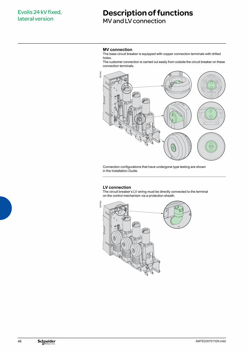
Description of functionsMV and LV connection
MV connectionThe base circuit breaker is equipped with copper connection terminals with drilled holes. The customer connection is carried out easily from outside the circuit breaker on these connection terminals.
DE
5766
1
Connection configurations that have undergone type testing are shown in the Installation Guide.
LV connectionThe circuit breaker’s LV wiring must be directly connected to the terminalon the control mechanism via a protection sheath.
DE
5766
2

49AMTED307011EN.indd
Evolis 24 kV fixed, lateral version
Description of functionsRI stored energy operating mechanismWiring diagram
Operation of the RI stored energy operating mechanismThis gives the device an opening and closing speed that is independent of the operator whether the order is electrical or manual.The electrical control mechanism carries out reclosing cycles and is automatically recharged by a geared motor each time after closing. It consists of:
b the stored energy operating mechanism which stores in springs the energy required to open and close the device
b a manual lever-operated spring arming device b a geared electrical arming device which automatically re-arms the control
mechanism as soon as the circuit breaker is closed (optional) b manual order devices by push buttons on the front panel of the device b an electrical remote closing device containing a release with an antipumping relay b an electrical opening order device comprising one or several release units which
can be of the following type: v shunt opening v undervoltage v Mitop, a low consumption release, used only with the Sepam 100 LA
protection relay. b an operation counter b an “open/closed” position indicator device with a mechanical indicator b a device for indicating “charged” operating mechanism status by mechanical
indicator and electrical contact (optional) b a module of 14 auxiliary contacts whose availability varies according
to the diagram used.
Wiring diagram (principle)
M
YF +anti-pumping
Motor Shunt closingrelease+ anti-pumpingsystem
Remote control
Shunt openingrelease
Under-voltagerelease
Low energyrelease(Mitop)
NO contacts
Changeovercontact
NC contacts
Close CB
Open CB
YM
M3
Mitop
“Control mechanism armed” indicator contact
YO1 YO2
DE
5940
9EN
PE
5716
4
50 AMTED307011EN.indd
Evolis 24 kV fixed, lateral version
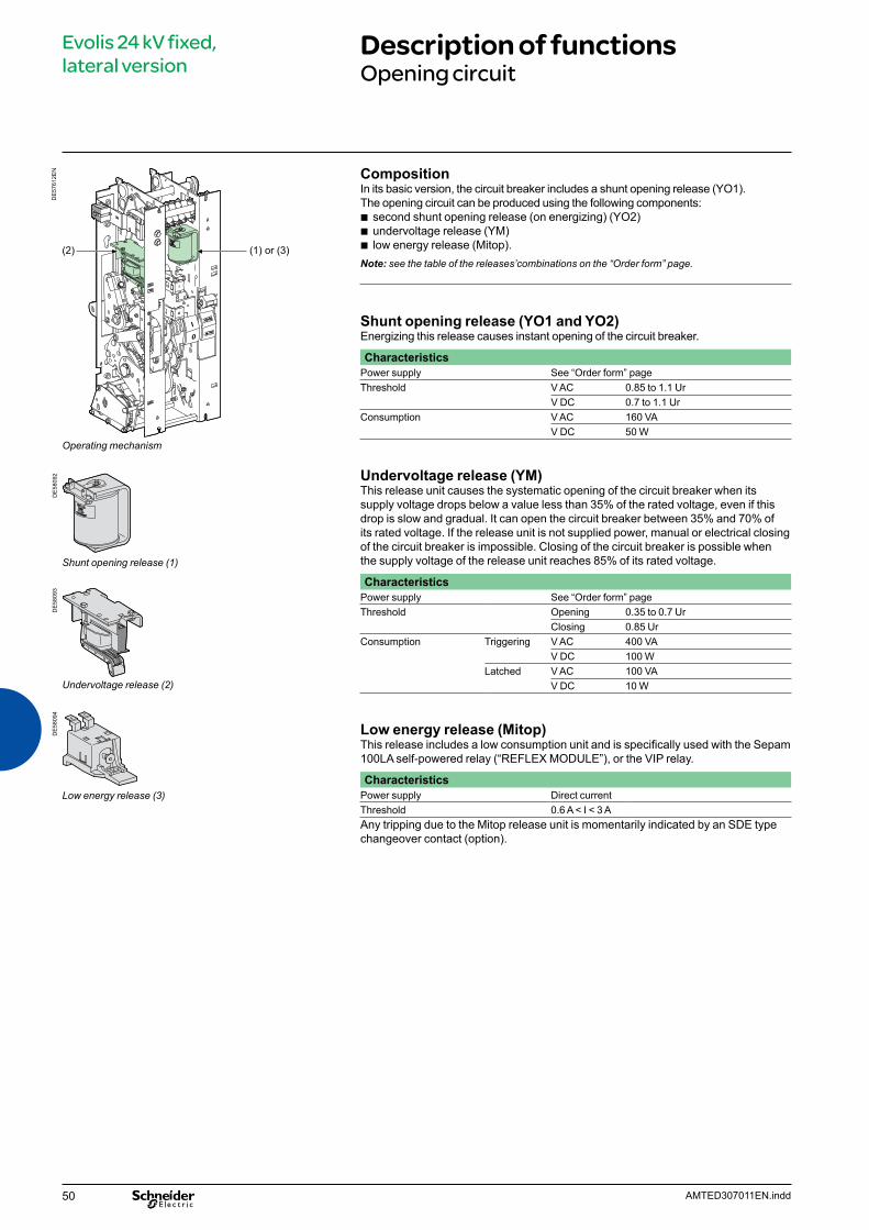
Description of functionsOpening circuit
DE
5761
2EN
Operating mechanism
Shunt opening release (1)
Undervoltage release (2)
Low energy release (3)
(1) or (3)(2)
CompositionIn its basic version, the circuit breaker includes a shunt opening release (YO1). The opening circuit can be produced using the following components:
b second shunt opening release (on energizing) (YO2) b undervoltage release (YM) b low energy release (Mitop).
Note: see the table of the releases’combinations on the “Order form” page.
Shunt opening release (YO1 and YO2)Energizing this release causes instant opening of the circuit breaker.
CharacteristicsPower supply See “Order form” pageThreshold V AC 0.85 to 1.1 Ur
V DC 0.7 to 1.1 UrConsumption V AC 160 VA
V DC 50 W
Undervoltage release (YM)This release unit causes the systematic opening of the circuit breaker when itssupply voltage drops below a value less than 35% of the rated voltage, even if thisdrop is slow and gradual. It can open the circuit breaker between 35% and 70% ofits rated voltage. If the release unit is not supplied power, manual or electrical closingof the circuit breaker is impossible. Closing of the circuit breaker is possible whenthe supply voltage of the release unit reaches 85% of its rated voltage.
CharacteristicsPower supply See “Order form” pageThreshold Opening 0.35 to 0.7 Ur
Closing 0.85 UrConsumption Triggering V AC 400 VA
V DC 100 WLatched V AC 100 VA
V DC 10 W
Low energy release (Mitop)This release includes a low consumption unit and is specifically used with the Sepam 100LA self-powered relay (“REFLEX MODULE”), or the VIP relay.
CharacteristicsPower supply Direct current Threshold 0.6 A < I < 3 AAny tripping due to the Mitop release unit is momentarily indicated by an SDE type changeover contact (option).
DE
5809
2D
E58
093
DE
5809
4

51AMTED307011EN.indd
Evolis 24 kV fixed, lateral version
Description of functionsRemote control
DE
5760
4
Operating mechanism
Electrical motor and gearing (4)
Shunt closing release (5)
Operation counter (6)
FunctionRemote control enables the remote opening and closing of the circuit breaker.
CompositionThe remote control mechanism comprises:
b an electrical motor with gearing b a shunt closing release (YF) combined with an anti-pumping device b an operation counter.
Electrical motor with gearing (M)The electrical motor carries out the automatic rearming of the stored energy unit as soon as the circuit breaker is closed. This allows the instant reclosing of the device after opening. The arming lever is only used as a backup operating mechanism in the case of the absence of the auxiliary power supply.The M3 contact indicates the end of arming operations.
CharacteristicsPower supply See “Order form” pageThreshold V AC/V DC 0.85 to 1.1 UrConsumption V AC 380 VA
V DC 380 W
Shunt closing release (YF)This release allows the remote closing of the circuit breaker when the operating mechanism is armed.
CharacteristicsPower supply See “Order form” pageThreshold V AC 0.85 to 1.1 Ur
V DC 0.85 to 1.1 UrConsumption V AC 160 VA
V DC 50 W
The shunt closing release is combined with an anti-pumping relay that enables priority to be given to opening in the case of a permanent closing order. This thus avoids the device being caught in an uncontrolled opening-closing cycle.
Operation counterThe operation counter is visible on the front panel.It displays the number of switching cycles (CO) that the device has carried out.
DE
5809
6D
E58
097
DE
5809
2
52 AMTED307011EN.indd
Evolis 24 kV fixed, lateral version
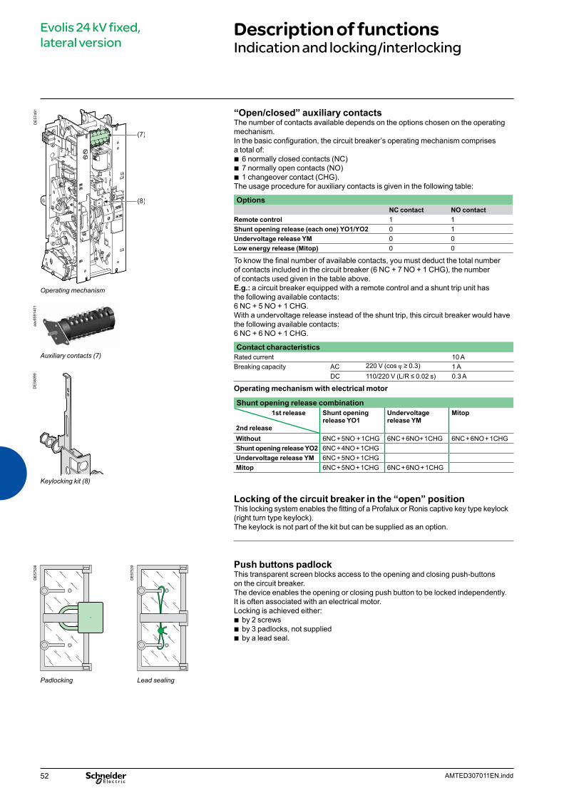
Description of functionsIndication and locking/interlocking
Operating mechanism
Auxiliary contacts (7)
Keylocking kit (8)
DE
5749
1D
E575
38
DE5
7539
Padlocking Lead sealing
DE
5809
9
“Open/closed” auxiliary contacts The number of contacts available depends on the options chosen on the operating mechanism.In the basic configuration, the circuit breaker’s operating mechanism comprises a total of:
b 6 normally closed contacts (NC) b 7 normally open contacts (NO) b 1 changeover contact (CHG).
The usage procedure for auxiliary contacts is given in the following table:
OptionsNC contact NO contact
Remote control 1 1Shunt opening release (each one) YO1/YO2 0 1Undervoltage release YM 0 0Low energy release (Mitop) 0 0
To know the final number of available contacts, you must deduct the total number of contacts included in the circuit breaker (6 NC + 7 NO + 1 CHG), the number of contacts used given in the table above.E.g.: a circuit breaker equipped with a remote control and a shunt trip unit has the following available contacts: 6 NC + 5 NO + 1 CHG. With a undervoltage release instead of the shunt trip, this circuit breaker would have the following available contacts: 6 NC + 6 NO + 1 CHG.
Contact characteristicsRated current 10 ABreaking capacity AC 220 V (cos j ≥ 0.3) 1 A
DC 110/220 V (L/R ≤ 0.02 s) 0.3 A
Operating mechanism with electrical motor
Shunt opening release combination1st release
2nd release
Shunt opening release YO1
Undervoltage release YM
Mitop
Without 6NC + 5NO + 1CHG 6NC + 6NO+ 1CHG 6NC + 6NO + 1CHGShunt opening release YO2 6NC + 4NO + 1CHGUndervoltage release YM 6NC + 5NO + 1CHGMitop 6NC + 5NO + 1CHG 6NC + 6NO + 1CHG
Locking of the circuit breaker in the “open” positionThis locking system enables the fitting of a Profalux or Ronis captive key type keylock (right turn type keylock). The keylock is not part of the kit but can be supplied as an option.
Push buttons padlockThis transparent screen blocks access to the opening and closing push-buttonson the circuit breaker.The device enables the opening or closing push button to be locked independently. It is often associated with an electrical motor.Locking is achieved either:
b by 2 screws b by 3 padlocks, not supplied b by a lead seal.
aav8
5914
01
53AMTED307011EN.indd
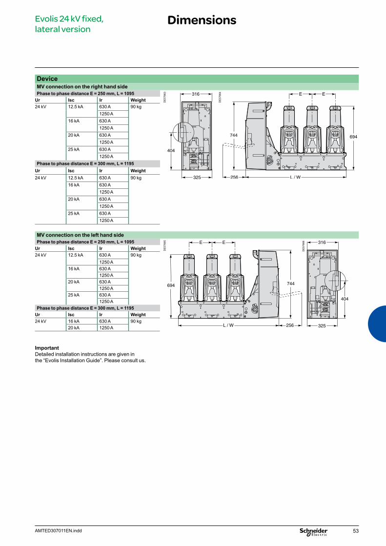
Evolis 24 kV fixed, lateral version
Dimensions
DeviceMV connection on the right hand side Phase to phase distance E = 250 mm, L = 1095
DE
5766
3
DE
5766
4
Ur Isc Ir Weight24 kV 12.5 kA 630 A 90 kg
1250 A16 kA 630 A
1250 A20 kA 630 A
1250 A25 kA 630 A
1250 APhase to phase distance E = 300 mm, L = 1195
Ur Isc Ir Weight24 kV 12.5 kA 630 A 90 kg
16 kA 630 A1250 A
20 kA 630 A1250 A
25 kA 630 A1250 A
MV connection on the left hand sidePhase to phase distance E = 250 mm, L = 1095
DE
5766
5
DE
5766
6
Ur Isc Ir Weight24 kV 12.5 kA 630 A 90 kg
1250 A16 kA 630 A
1250 A20 kA 630 A
1250 A25 kA 630 A
1250 APhase to phase distance E = 300 mm, L = 1195
Ur Isc Ir Weight24 kV 16 kA 630 A 90 kg
20 kA 1250 A
Important Detailed installation instructions are given in the “Evolis Installation Guide”. Please consult us.
54 AMTED307011EN.indd
Evolis 24 kV fixed, lateral version
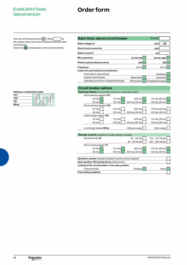
Order form
Releases combinations tableYO1 1 1 1 1YO2 1YM 1 1 1Mitop 1 1
Only one of the boxes (ticked X or filled by the needed value) have to be considered between each horizontal line. Green box X corresponds to none priced functions.
Basic fixed, lateral circuit breaker Quantity
Rated voltage Ur (kV) 24
Short circuit current Isc (kA)
Rated current Ir (A)
MV connection On the left On the right
Phase to phase distance (mm) 250 300
Frequency 50 Hz 60 Hz Colour for push buttons and indicators
Push buttons open/closed: Red/black Indicator open/closed: Black/white Green/red Operating mechanism charged/discharged: White/yellow Charged/discharged
Circuit breaker optionsOpening release (see possible choices in combination table)
Shunt opening release YO124 Vdc 110 Vdc 220 Vdc 110 Vac (50 Hz) 48 Vdc 125 Vdc 220 Vac (50 Hz) 120 Vac (60 Hz)
Shunt opening release YO224 Vdc 110 Vdc 220 Vdc 110 Vac (50 Hz) 48 Vdc 125 Vdc 220 Vac (50 Hz) 120 Vac (60 Hz)
Undervoltage release YM24 Vdc 110 Vdc 220 Vdc 110 Vac (50 Hz) 48 Vdc 125 Vdc 220 Vac (50 Hz) 120 Vac (60 Hz)
Low energy release Mitop Without contact With contact
Remote control (operation counter already included)Electrical motor M 24…32 Vdc 110…127 Vdc/ac
48…60 Vdc/ac 220…250 Vdc/ac Shunt closing release YF
24 Vdc 110 Vdc 220 Vdc 110 Vac (50 Hz) 48 Vdc 125 Vdc 220 Vac (50 Hz) 120 Vac (60 Hz)
Operation counter (already included if remote control supplied) Open position CB locking device (without lock) Locking of the circuit breaker in the open position
Locks and keys Profalux Ronis Push buttons padlock
55AMTED307011EN.indd
Evolis 24 kV fixed, lateral version
Offer structureSeparated components
The following components can be ordered separately and can be adapted or replaced by the customer.
Remote control Ref.
Shunt opening release YO1 or YO2
DE
5809
2 24 Vdc AAA10 11548 Vdc AAA10 116110 Vdc AAA10 117125-127 Vdc AAA10 118220 Vdc AAA10 119110 Vac 50 Hz AAA10 120220-230 Vac 50 Hz AAA10 121120 Vac 60 Hz AAA10 122
Shunt closing release YF
DE
5809
2 24 Vdc AAA10 10648 Vdc AAA10 107110 Vdc AAA10 108125-127 Vdc AAA10 109220 Vdc AAA10 110110 Vac 50 Hz AAA10 111220-230 Vac 50 Hz AAA10 112120 Vac 60 Hz AAA10 113
Undervoltage release YM
DE
5809
3 24 Vdc AAA10 12448 Vdc AAA10 125110 Vdc AAA10 126125-127 Vdc AAA10 127220 Vdc AAA10 128110 Vac 50 Hz AAA10 129220-230 Vac 50 Hz AAA10 130120 Vac 60 Hz AAA10 131
Low energy release Mitop
DE
5809
4 Without contact 0889308AWith contact 0889308B
Electrical motor
DE
5762
1 24…32 Vdc AAA10 02748…60 Vac/dc AAA10 028100…127 Vac/dc AAA10 029220…250 Vac/dc AAA10 030
DE
5762
2 Gear reducer AAA10 065
Locking/interlocking Ref.
DE
5763
8
DE
5753
5
Fig. 1 Fig. 2
Open position circuit breaker locking device (without lock) (fig. 1) AAA10 092Ronis lock AAA10 058Profalux lock AAA10 059Push buttons padlock (fig. 2) 48536
56 AMTED307011EN.indd
Evolis 24 kV fixed, lateral version
Services
The following components can only be adapted or replaced on site by staff trained by Schneider Electric
b Remote control mechanism (comprising: electrical motor, gearing, shunt closing release, anti-pumping relay, operation counter)
b Operation counter b Low energy release (Mitop) b Circuit breaker front cover.

57AMTED307011EN.indd
EVOset 24 kV fixed, lateral version
Contents
Presentation 58Main characteristics 59Description of functions 60 MV and LV connection 60RI stored energy operating mechanism 61Wiring diagram 61Opening circuit 62Remote control 63Indication and locking/interlocking 64
Protection, monitoring and control 65EVOset: integrated protection chain by a VIP relay 65VIP30 and VIP35 protection units 66VIP300P and VIP300LL protection units 68Current sensors and test unit for VIP relays 70
Dimensions 71Order form 72Offer structure 73Separated components 73
Services 74

58 AMTED307011EN.indd
EVOset 24 kV fixed, lateral version
Presentation
EVOset 24 kV fixed, lateral version MV connection on the right hand side
PE
5809
0
Description of the device The Evolis circuit breaker comprises a basic fixed version:
b 3 poles integrated in a “sealed pressure system” type insulating enclosure b a RI type, spring-operated stored energy control mechanism, electrifiable.
This gives the device an opening and closing speed that is independent of the operator, for both electrical and manual orders. It enables reclosing cycles to be carried out
b a lateral panel housing the manual operating mechanism and status indicators b upstream and downstream terminals for the power circuit connection b a terminal block for connection of external auxiliary circuits b an independent protection chain.
Each device can also be fitted with the following options: b circuit breaker locking in the open position by a keylock installed on the front plate
of the operating mechanism.
Applications Evolis circuit breakers are three-pole indoor MV circuit breakers. They are mainly used for operation and protection of public, industrial and tertiary distribution networks of 24 kV. Through their compact dimensions and harmonized range, Evolis circuit breakers are positioned very favorably on the retrofit market.
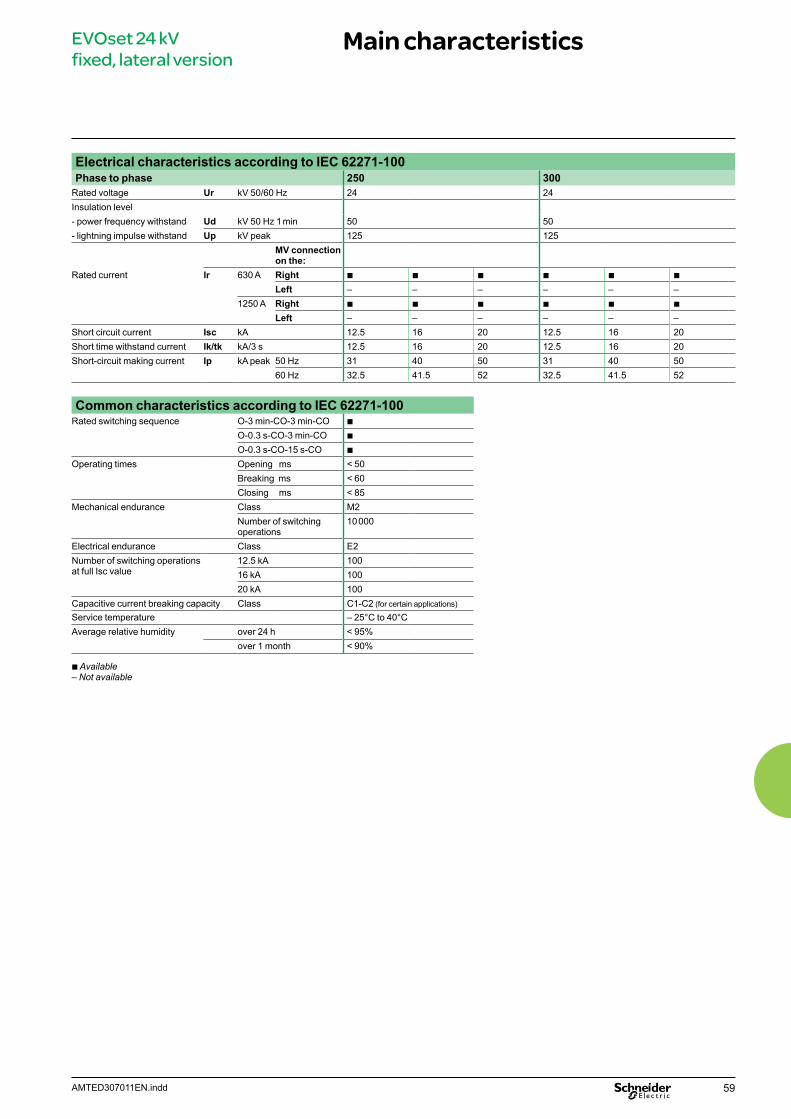
59AMTED307011EN.indd
EVOset 24 kV fixed, lateral version
Main characteristics
Electrical characteristics according to IEC 62271-100Phase to phase 250 300
Rated voltage Ur kV 50/60 Hz 24 24Insulation level- power frequency withstand Ud kV 50 Hz 1 min 50 50- lightning impulse withstand Up kV peak 125 125
MV connection on the:
Rated current Ir 630 A Right b b b b b b
Left – – – – – –1250 A Right b b b b b b
Left – – – – – –Short circuit current Isc kA 12.5 16 20 12.5 16 20Short time withstand current Ik/tk kA/3 s 12.5 16 20 12.5 16 20Short-circuit making current Ip kA peak 50 Hz 31 40 50 31 40 50
60 Hz 32.5 41.5 52 32.5 41.5 52
Common characteristics according to IEC 62271-100Rated switching sequence O-3 min-CO-3 min-CO b
O-0.3 s-CO-3 min-CO b
O-0.3 s-CO-15 s-CO b
Operating times Opening ms < 50Breaking ms < 60Closing ms < 85
Mechanical endurance Class M2Number of switching operations
10 000
Electrical endurance Class E2Number of switching operations at full Isc value
12.5 kA 10016 kA 10020 kA 100
Capacitive current breaking capacity Class C1-C2 (for certain applications)
Service temperature – 25°C to 40°CAverage relative humidity over 24 h < 95%
over 1 month < 90%
b Available– Not available
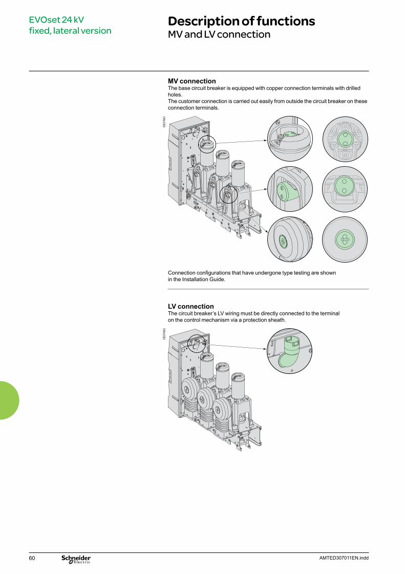
60 AMTED307011EN.indd
EVOset 24 kV fixed, lateral version
Description of functionsMV and LV connection
MV connectionThe base circuit breaker is equipped with copper connection terminals with drilled holes. The customer connection is carried out easily from outside the circuit breaker on these connection terminals.
DE
5766
1
Connection configurations that have undergone type testing are shown in the Installation Guide.
LV connectionThe circuit breaker’s LV wiring must be directly connected to the terminalon the control mechanism via a protection sheath.
DE
5766
2
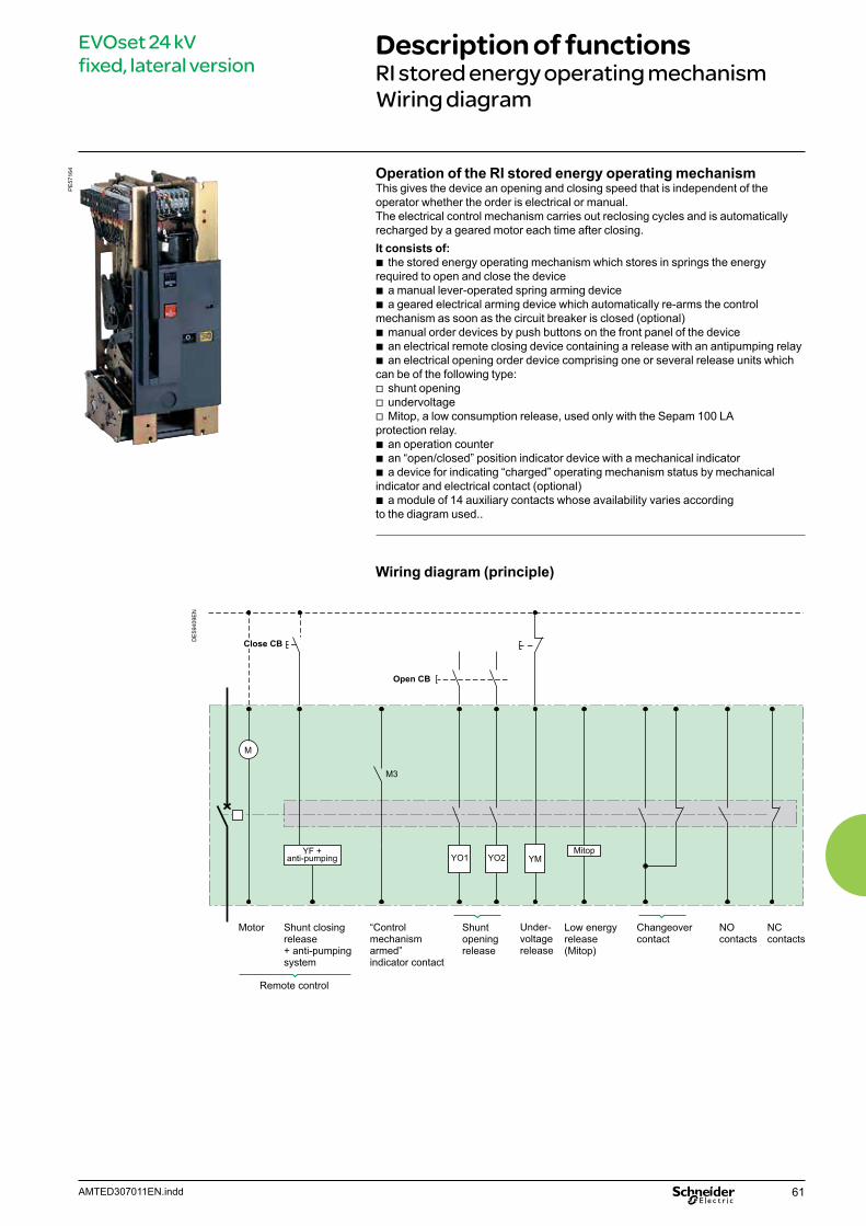
61AMTED307011EN.indd
EVOset 24 kV fixed, lateral version
Description of functionsRI stored energy operating mechanismWiring diagram
Operation of the RI stored energy operating mechanismThis gives the device an opening and closing speed that is independent of the operator whether the order is electrical or manual.The electrical control mechanism carries out reclosing cycles and is automatically recharged by a geared motor each time after closing. It consists of:
b the stored energy operating mechanism which stores in springs the energy required to open and close the device
b a manual lever-operated spring arming device b a geared electrical arming device which automatically re-arms the control
mechanism as soon as the circuit breaker is closed (optional) b manual order devices by push buttons on the front panel of the device b an electrical remote closing device containing a release with an antipumping relay b an electrical opening order device comprising one or several release units which
can be of the following type: v shunt opening v undervoltage v Mitop, a low consumption release, used only with the Sepam 100 LA
protection relay. b an operation counter b an “open/closed” position indicator device with a mechanical indicator b a device for indicating “charged” operating mechanism status by mechanical
indicator and electrical contact (optional) b a module of 14 auxiliary contacts whose availability varies according
to the diagram used..
Wiring diagram (principle)
M
YF +anti-pumping
Motor Shunt closingrelease+ anti-pumpingsystem
Remote control
Shunt openingrelease
Under-voltagerelease
Low energyrelease(Mitop)
NO contacts
Changeovercontact
NC contacts
Close CB
Open CB
YM
M3
Mitop
“Control mechanism armed” indicator contact
YO1 YO2
DE
5940
9EN
PE
5716
4
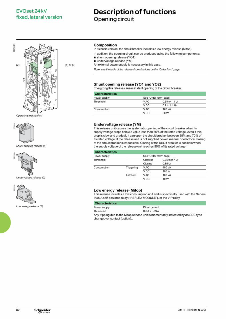
62 AMTED307011EN.indd
EVOset 24 kV fixed, lateral version
Description of functionsOpening circuit
DE
5761
2EN
Operating mechanism
Shunt opening release (1)
Undervoltage release (2)
Low energy release (3)
(1) or (3)(2)
CompositionIn its basic version, the circuit breaker includes a low energy release (Mitop). In addition, the opening circuit can be produced using the following components:
b shunt opening release (YO1) b undervoltage release (YM).
An external power supply is necessary in this case.Note: see the table of the releases’combinations on the “Order form” page.
Shunt opening release (YO1 and YO2)Energizing this release causes instant opening of the circuit breaker.
CharacteristicsPower supply See “Order form” pageThreshold V AC 0.85 to 1.1 Ur
V DC 0.7 to 1.1 UrConsumption V AC 160 VA
V DC 50 W
Undervoltage release (YM)This release unit causes the systematic opening of the circuit breaker when itssupply voltage drops below a value less than 35% of the rated voltage, even if thisdrop is slow and gradual. It can open the circuit breaker between 35% and 70% ofits rated voltage. If the release unit is not supplied power, manual or electrical closingof the circuit breaker is impossible. Closing of the circuit breaker is possible whenthe supply voltage of the release unit reaches 85% of its rated voltage.
CharacteristicsPower supply See “Order form” pageThreshold Opening 0.35 to 0.7 Ur
Closing 0.85 UrConsumption Triggering V AC 400 VA
V DC 100 WLatched V AC 100 VA
V DC 10 W
Low energy release (Mitop)This release includes a low consumption unit and is specifically used with the Sepam 100LA self-powered relay (“REFLEX MODULE”), or the VIP relay.
CharacteristicsPower supply Direct current Threshold 0.6 A < I < 3 AAny tripping due to the Mitop release unit is momentarily indicated by an SDE type changeover contact (option)..
DE
5809
2D
E58
093
DE
5809
4
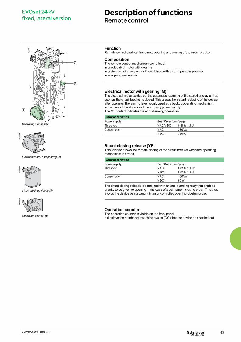
63AMTED307011EN.indd
EVOset 24 kV fixed, lateral version
Description of functionsRemote control
DE
5760
4
Operating mechanism
Electrical motor and gearing (4)
Shunt closing release (5)
Operation counter (6)
FunctionRemote control enables the remote opening and closing of the circuit breaker.
CompositionThe remote control mechanism comprises:
b an electrical motor with gearing b a shunt closing release (YF) combined with an anti-pumping device b an operation counter.
Electrical motor with gearing (M)The electrical motor carries out the automatic rearming of the stored energy unit as soon as the circuit breaker is closed. This allows the instant reclosing of the device after opening. The arming lever is only used as a backup operating mechanism in the case of the absence of the auxiliary power supply.The M3 contact indicates the end of arming operations.
CharacteristicsPower supply See “Order form” pageThreshold V AC/V DC 0.85 to 1.1 UrConsumption V AC 380 VA
V DC 380 W
Shunt closing release (YF)This release allows the remote closing of the circuit breaker when the operating mechanism is armed.
CharacteristicsPower supply See “Order form” pageThreshold V AC 0.85 to 1.1 Ur
V DC 0.85 to 1.1 UrConsumption V AC 160 VA
V DC 50 W
The shunt closing release is combined with an anti-pumping relay that enables priority to be given to opening in the case of a permanent closing order. This thus avoids the device being caught in an uncontrolled opening-closing cycle.
Operation counterThe operation counter is visible on the front panel.It displays the number of switching cycles (CO) that the device has carried out.
DE
5809
6D
E58
097
DE
5809
2
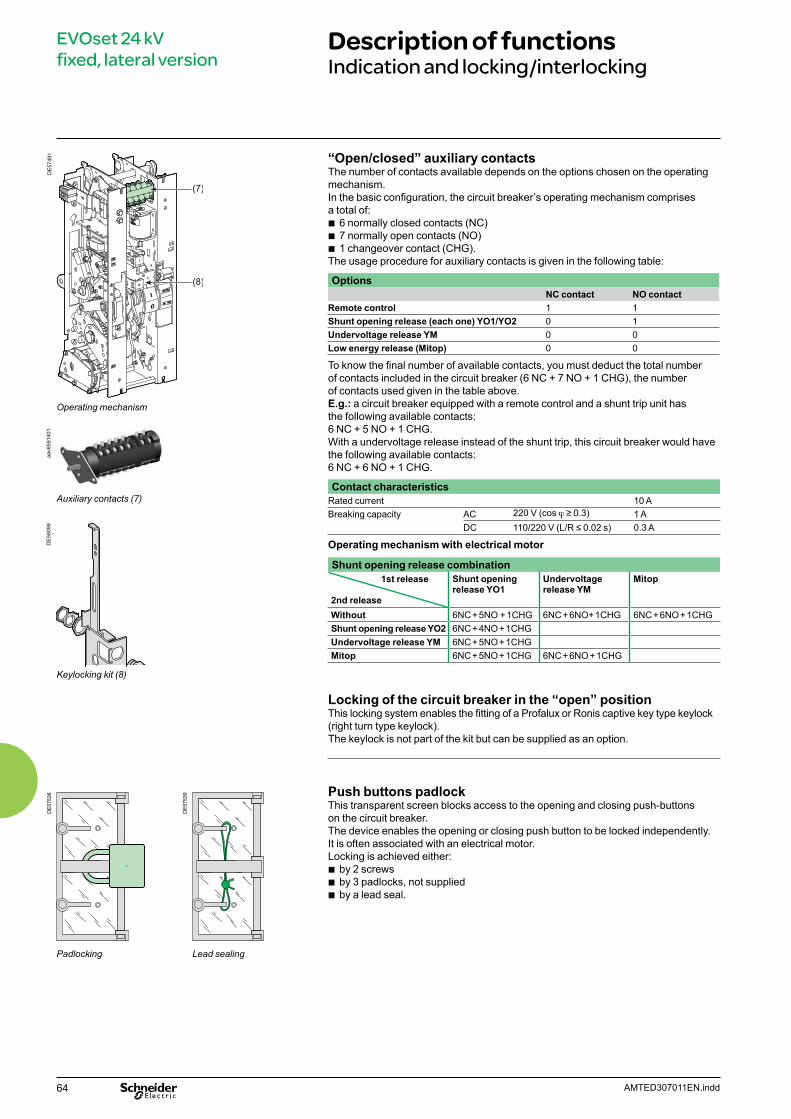
64 AMTED307011EN.indd
EVOset 24 kV fixed, lateral version
Description of functionsIndication and locking/interlocking
Operating mechanism
Auxiliary contacts (7)
Keylocking kit (8)
DE
5749
1D
E575
38
DE5
7539
Padlocking Lead sealing
DE
5809
9
“Open/closed” auxiliary contacts The number of contacts available depends on the options chosen on the operating mechanism.In the basic configuration, the circuit breaker’s operating mechanism comprises a total of:
b 6 normally closed contacts (NC) b 7 normally open contacts (NO) b 1 changeover contact (CHG).
The usage procedure for auxiliary contacts is given in the following table:
OptionsNC contact NO contact
Remote control 1 1Shunt opening release (each one) YO1/YO2 0 1Undervoltage release YM 0 0Low energy release (Mitop) 0 0
To know the final number of available contacts, you must deduct the total number of contacts included in the circuit breaker (6 NC + 7 NO + 1 CHG), the number of contacts used given in the table above.E.g.: a circuit breaker equipped with a remote control and a shunt trip unit has the following available contacts: 6 NC + 5 NO + 1 CHG. With a undervoltage release instead of the shunt trip, this circuit breaker would have the following available contacts: 6 NC + 6 NO + 1 CHG.
Contact characteristicsRated current 10 ABreaking capacity AC 220 V (cos j ≥ 0.3) 1 A
DC 110/220 V (L/R ≤ 0.02 s) 0.3 A
Operating mechanism with electrical motor
Shunt opening release combination1st release
2nd release
Shunt opening release YO1
Undervoltage release YM
Mitop
Without 6NC + 5NO + 1CHG 6NC + 6NO+ 1CHG 6NC + 6NO + 1CHGShunt opening release YO2 6NC + 4NO + 1CHGUndervoltage release YM 6NC + 5NO + 1CHGMitop 6NC + 5NO + 1CHG 6NC + 6NO + 1CHG
Locking of the circuit breaker in the “open” positionThis locking system enables the fitting of a Profalux or Ronis captive key type keylock (right turn type keylock). The keylock is not part of the kit but can be supplied as an option.
Push buttons padlockThis transparent screen blocks access to the opening and closing push-buttonson the circuit breaker.The device enables the opening or closing push button to be locked independently. It is often associated with an electrical motor.Locking is achieved either:
b by 2 screws b by 3 padlocks, not supplied b by a lead seal.
aav8
5914
01
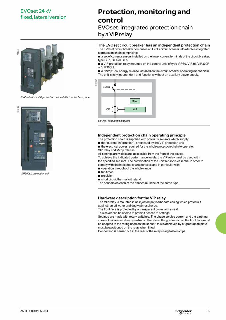
65AMTED307011EN.indd
EVOset 24 kV fixed, lateral version
Protection, monitoring and control EVOset: integrated protection chain by a VIP relay
The EVOset circuit breaker has an independent protection chain The EVOset circuit breaker comprises an Evolis circuit breaker into which is integrated a protection chain comprising:
b a set of current sensors installed on the lower current terminals of the circuit breaker: type CEc, CEa or CEb
b a VIP protection relay mounted on the control unit: of type VIP30, VIP35, VIP300P or VIP300LL
b a “Mitop” low energy release installed on the circuit breaker operating mechanism. The unit is fully independent and functions without an auxiliary power supply.
DE
5766
7
Evolis
Mitop
VIPCE
EVOset schematic diagram
Independent protection chain operating principleThe protection chain is supplied with power by sensors which supply:
b the “current” information”, processed by the VIP protection unit b the electrical power required for the whole protection chain to operate;
VIP relay and Mitop release.All settings are visible and accessible from the front of the device. To achieve the indicated performance levels, the VIP relay must be used withthe specified sensors. The combination of the unit/sensor is essential in order to comply with the indicated characteristics and in particular with:
b operation throughout the whole range b trip times b precision b short circuit thermal withstand.
The sensors on each of the phases must be of the same type.
Hardware description for the VIP relayThe VIP relay is mounted in an injected polycarbonate casing which protects it against run off water and dusty atmospheres.The front face is protected by a transparent cover with a seal. This cover can be sealed to prohibit access to settings.Settings are made with rotary switches. The phase service current and the earthing current limit are set directly in Amps. Therefore, the graduation on the front face must be adapted to the rating used on the sensor; this is achieved by a “graduation plate” must be positioned on the relay when fitted. Connection is carried out at the rear of the relay using fast-on clips.
EVOset with a VIP protection unit installed on the front panel
VIP300LL protection unit
PE
5809
0P
E58
101
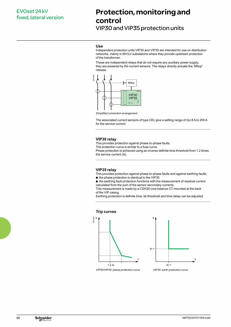
66 AMTED307011EN.indd
EVOset 24 kV fixed, lateral version
Protection, monitoring and control VIP30 and VIP35 protection units
UseIndependent protection units VIP30 and VIP35 are intended for use on distribution networks, mainly in MV/LV substations where they provide upstream protection of the transformer. These are independent relays that do not require any auxiliary power supply;they are powered by the current sensors. The relays directly actuate the “Mitop” release.
DE
5766
8
Mitop
VIP30VIP35
Simplified connection arrangement
The associated current sensors of type CEc give a setting range of (Is) 8 A to 200 A for the service current.
VIP30 relay This provides protection against phase-to-phase faults.The protection curve is similar to a fuse curve.Phase protection is achieved using an inverse definite time threshold from 1.2 times the service current (Is).
VIP35 relayThis provides protection against phase-to-phase faults and against earthing faults:
b the phase protection is identical to the VIP30 b the earthing fault protection functions with the measurement of residual current
calculated from the sum of the sensor secondary currents. This measurement is made by a CSH30 core balance CT mounted at the back of the VIP casing. Earthing protection is definite time; its threshold and time delay can be adjusted.
Trip curves
DE
5766
9
1.2 Is
I
Io >
to >
t
I
t
VIP30/VIP35: phase protection curve VIP35: earth protection curve
67AMTED307011EN.indd
EVOset 24 kV fixed, lateral version
Protection, monitoring and control VIP30 and VIP35 protection units (cont.)
Phase protection trip curve: VIP30 and VIP35
DE
5767
0
0.01
0.1
1
10
100
T (s)
I/Ismax.typ.min.
0 51.2 Is
10 15 20 25 30 35
68 AMTED307011EN.indd
EVOset 24 kV fixed, lateral version
Protection, monitoring and control VIP300P and VIP300LL protection units
UseSelf powered protection units VIP300P and 300LL are intended for use on distribution networks. They can be used to protect MV/LV transformers, to protect the incoming of the industrial installation, but also to protect feeders. These are self powered relays that do not require any auxiliary power supply;they are powered by the current sensors. The relays directly actuate the “Mitop” release.
DE
5740
2
Mitop
VIP300
DE
5740
3 t
t >
t >>
I >>10 Is1,2 Is
I
Simplified connection arrangement Phase and earthing protection curve
The associated current sensors of type CEa and CEb give a setting range for the service current (Is) of 10 A to 1250 A.
VIP300P relayThis provides protection against phase-to-phase faultsPhase protection has two independently adjustable thresholds:
b the lower threshold can be chosen to be either definite time or inverse definite time. It can be executed according to the RI curve.
b the higher threshold is definite time.The inverse definite time curves are in conformity with standard IEC 60255-3.They are either of type inverse (SI), very inverse (VI) and extremely inverse (EI).
VIP300LL relayThis provides protection against phase-to-phase faults and against earthing faults:
b the phase protection is identical to the VIP300P b earthing fault protection functions with the measurement of residual current:
this is carried out based on the sum of secondary currents in the sensors. As for phase protection, earthing protection has two independently adjustable thresholds.
IndicationTwo indicators show the origin of tripping (phase or earth). They stay in position after breaking the relay power supply.Two LED indicator lights (phase and earth) show that the lower threshold has been exceeded and that the time delay has been started.
69AMTED307011EN.indd
EVOset 24 kV fixed, lateral version
Protection, monitoring and control VIP300P and VIP300LL protection units (cont.)
Trip curves
DE
5740
4
Is 1.2 Is 10 Is I >>
t >>
t >
Is I >>I >
t >>
t >
With an inverse definite time lower threshold With a definite time lower threshold
Inverse definite time trip curves
DE
5740
5
1000.01
0.1
1
10
100
101.2 Is
I/Is
t (s)
1
0.60.40.30.2
0.10.070.05
0.15
11.52346
0.611.52346
0.40.30.20.150.10.070.05
1000.01
0.1
1
10
100
10
I/Is
t (s)
1
RI curve SI curve
DE
5740
6
1000.01
0.1
1
10
100
1000
101.2 Is
I/Is
t (s)
1
0.60.40.30.20.150.10.070.05
11.52346
1000.01
0.1
1
10
100
1000
101.2 Is
I/Is
t (s)
1
0.60.40.30.20.150.10.070.05
11.52346
VI curve EI curve
70 AMTED307011EN.indd
EVOset 24 kV fixed, lateral version
Protection, monitoring and controlCurrent sensors and test unit for VIP relays
CE type current sensors
Current sensors for VIP relaysIn order to achieve the specified performance levels, the protection relays must be used with the specified sensors. The relay/sensor pairing is indissociable in order to comply with characteristics and in particular:
b operation throughout the whole range b response time b precision b short circuit thermal withstand.
Sensors choice Relay Service current (Is)CEc VIP30/VIP35 8 A to 200 ACEa VIP300P/VIP300LL 10 A to 200 ACEb VIP300P/VIP300LL 63 A to 1250 A
VAP6 test unit for VIP relaysVIP type protection units have a “test” socket to connect a VAP6 test unit. This portable unit with its own power supply enables the correct functioningof the protection relay to be checked.
VAP6 test unit
PE
5593
5P
E56
614

71AMTED307011EN.indd
EVOset 24 kV fixed, lateral version
Dimensions
DeviceMV connection on the right hand side Phase to phase distance E = 250 mm, L = 1095
DE
5767
1
DE
5767
2
Ur Isc Ir Weight24 kV 12.5 kA 630 A 120 kg
1250 A16 kA 630 A
1250 A20 kA 630 A
1250 APhase to phase distance E = 300 mm, L = 1195
Ur Isc Ir Weight24 kV 12.5 kA 630 A 120 kg
1250 A16 kA 630 A
1250 A20 kA 630 A
1250 A
Important Detailed installation instructions are given in the “Evolis Installation Guide”. Please consult us.
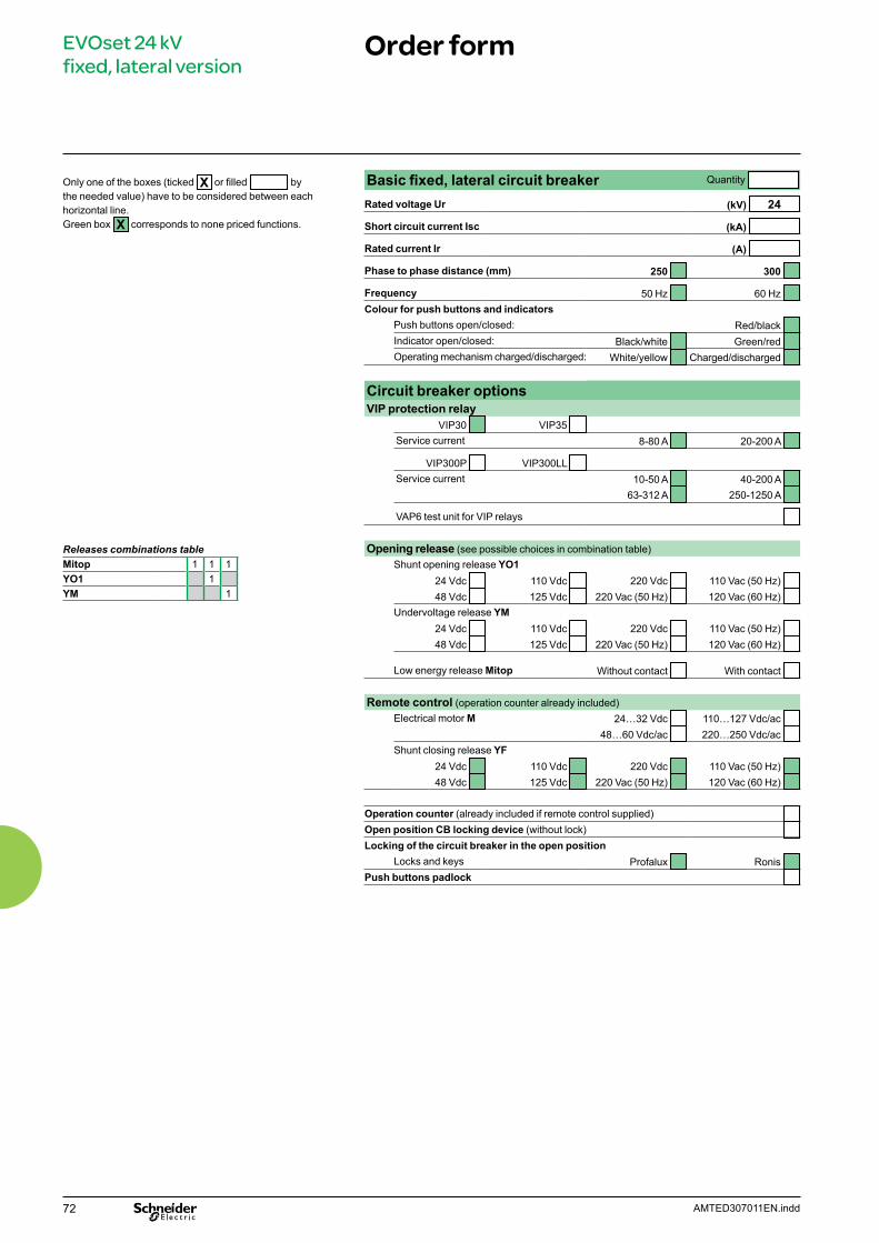
72 AMTED307011EN.indd
EVOset 24 kV fixed, lateral version
Order form
Releases combinations tableMitop 1 1 1YO1 1YM 1
Only one of the boxes (ticked X or filled by the needed value) have to be considered between each horizontal line. Green box X corresponds to none priced functions.
Basic fixed, lateral circuit breaker Quantity
Rated voltage Ur (kV) 24
Short circuit current Isc (kA)
Rated current Ir (A)
Phase to phase distance (mm) 250 300
Frequency 50 Hz 60 Hz Colour for push buttons and indicators
Push buttons open/closed: Red/black Indicator open/closed: Black/white Green/red Operating mechanism charged/discharged: White/yellow Charged/discharged
Circuit breaker optionsVIP protection relay
VIP30 VIP35 Service current 8-80 A 20-200 A
VIP300P VIP300LL Service current 10-50 A 40-200 A
63-312 A 250-1250 A
VAP6 test unit for VIP relays
Opening release (see possible choices in combination table)Shunt opening release YO1
24 Vdc 110 Vdc 220 Vdc 110 Vac (50 Hz) 48 Vdc 125 Vdc 220 Vac (50 Hz) 120 Vac (60 Hz)
Undervoltage release YM24 Vdc 110 Vdc 220 Vdc 110 Vac (50 Hz) 48 Vdc 125 Vdc 220 Vac (50 Hz) 120 Vac (60 Hz)
Low energy release Mitop Without contact With contact
Remote control (operation counter already included)Electrical motor M 24…32 Vdc 110…127 Vdc/ac
48…60 Vdc/ac 220…250 Vdc/ac Shunt closing release YF
24 Vdc 110 Vdc 220 Vdc 110 Vac (50 Hz) 48 Vdc 125 Vdc 220 Vac (50 Hz) 120 Vac (60 Hz)
Operation counter (already included if remote control supplied) Open position CB locking device (without lock) Locking of the circuit breaker in the open position
Locks and keys Profalux Ronis Push buttons padlock
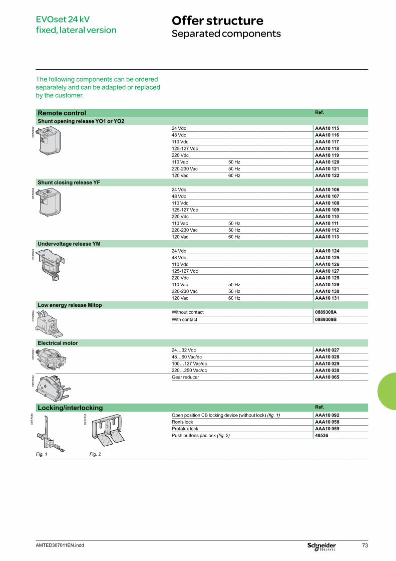
73AMTED307011EN.indd
EVOset 24 kV fixed, lateral version
Offer structureSeparated components
The following components can be ordered separately and can be adapted or replaced by the customer.
Remote control Ref.
Shunt opening release YO1 or YO2
DE
5809
2 24 Vdc AAA10 11548 Vdc AAA10 116110 Vdc AAA10 117125-127 Vdc AAA10 118220 Vdc AAA10 119110 Vac 50 Hz AAA10 120220-230 Vac 50 Hz AAA10 121120 Vac 60 Hz AAA10 122
Shunt closing release YF
DE
5809
2 24 Vdc AAA10 10648 Vdc AAA10 107110 Vdc AAA10 108125-127 Vdc AAA10 109220 Vdc AAA10 110110 Vac 50 Hz AAA10 111220-230 Vac 50 Hz AAA10 112120 Vac 60 Hz AAA10 113
Undervoltage release YM
DE
5809
3 24 Vdc AAA10 12448 Vdc AAA10 125110 Vdc AAA10 126125-127 Vdc AAA10 127220 Vdc AAA10 128110 Vac 50 Hz AAA10 129220-230 Vac 50 Hz AAA10 130120 Vac 60 Hz AAA10 131
Low energy release Mitop
DE
5809
4 Without contact 0889308AWith contact 0889308B
Electrical motor
DE
5762
1 24…32 Vdc AAA10 02748…60 Vac/dc AAA10 028100…127 Vac/dc AAA10 029220…250 Vac/dc AAA10 030
DE
5762
2 Gear reducer AAA10 065
Locking/interlocking Ref.
DE
5763
8
DE
5753
5
Fig. 1 Fig. 2
Open position CB locking device (without lock) (fig. 1) AAA10 092Ronis lock AAA10 058Profalux lock AAA10 059Push buttons padlock (fig. 2) 48536

74 AMTED307011EN.indd
EVOset 24 kV fixed, lateral version
Services
The following components can only be adapted or replaced on site by staff trained by Schneider Electric
b Remote control mechanism (comprising: electrical motor, gearing, shunt closing release, anti-pumping relay, operation counter)
b Operation counter b Low energy release (Mitop) b Circuit breaker front cover.

75AMTED307011EN.indd
Notes

76 AMTED307011EN.indd
Notes


AMTED307011EN 02-2014
AR
T.83
1046
© S
chne
ider
Ele
ctric
Indu
strie
s S
AS
- A
ll rig
hts
rese
rved
As standards, specifications and designs change from time to time, please ask for confirmation of the information given in this publication.
Publishing: Schneider Electric Industries SASDesign: Schneider Electric Industries SASPrinting: Imprimerie du Pont de Claix/JPF - Made in France
This document has been printed on ecological paper
Schneider Electric Industries SAS35, rue Joseph Monier CS 30323 F - 92506 Rueil Malmaison Cedex
RCS Nanterre 954 503 439 Capital social 896 313 776 €www.schneider-electric.com