Embed Size (px)
DESCRIPTION
ECE-1020 Introduction to Electrical and Computer Engineering. Introduction to Arduino. Prepared by R. Lamond. What is Arduino?. - PowerPoint PPT Presentation
Citation preview

ECE-1020Introduction to Electrical and
Computer EngineeringIntroduction to Arduino
Prepared by R. Lamond

“Arduino is an open-source electronics prototyping platform based on flexible, easy-to-use hardware and software. It's intended for artists, designers, hobbyists, and anyone interested in creating interactive objects or environments” (arduino.cc)
Consists of both software and hardware: Software: The Arduino language (a variant of C) Hardware: The Arduino Uno in our case (other
boards exist)
What is Arduino?
Gather sensor data Actuate servos Process image data and light LEDs Communicate with smartphones for home
automation Many, many more possibilities!
Arduino (or a similar microcontroller) may be crucial to your senior design project!
What can I do with Arduino?

Arduino Can Do Great Things!

Meet the Board
USBPORT
Digital / PWM Ports
Analog PortsPower Ports
Microprocessor
5 V
We’ll talk about the Arduino later on.
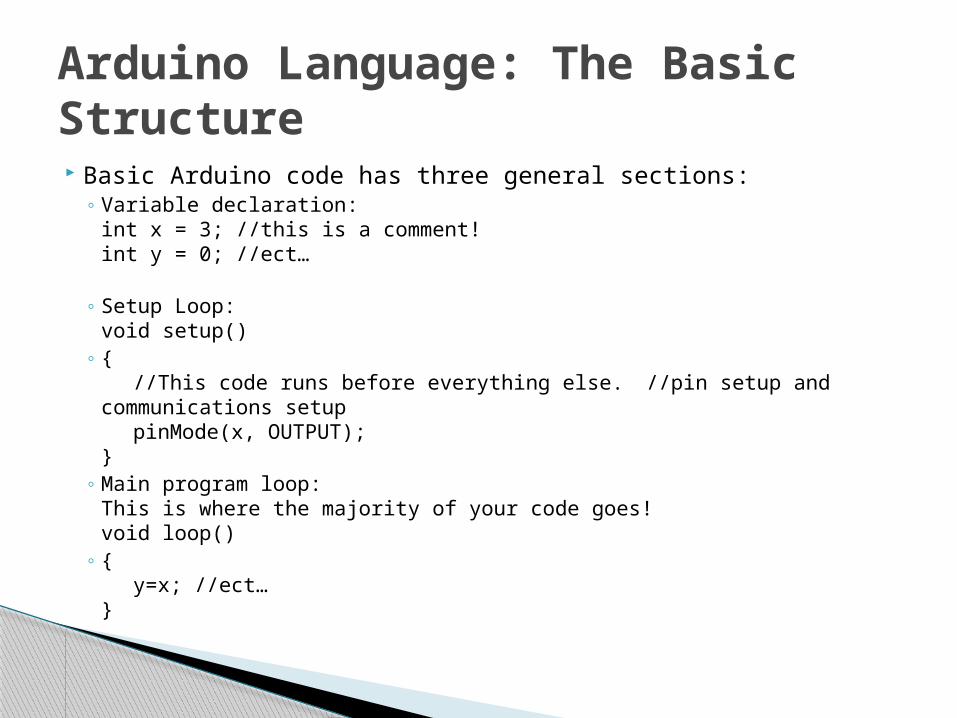
Basic Arduino code has three general sections: Variable declaration:int x = 3; //this is a comment!int y = 0; //ect…
Setup Loop:void setup()
//This code runs before everything else. //pin
setup and communications setup pinMode(x, OUTPUT);
Main program loop:This is where the majority of your code goes!void loop()
y=x; //ect…
Arduino Language: The Basic Structure
Arduino syntax is quite similar to interactive C as they are both “C-based” languages
If you get confused about syntax today, think back to your work with robots!
Arduino commands are quite different from IC, so you may have to consult references (or your instructor) to determine the proper usage.
A note on syntax
Become familiar with the Arduino Uno and Language: Understand and upload some sample code to the
Arduino Uno
Understand and edit some more complex code, modify it to add functionality, and upload to the Arduino Uno
Today’s Objectives

But what are we actually making? A hardware/software system which makes a single
color LED blink on and off A hardware/software system which makes three
colored LEDs pulse between very dim and very bright
What parts will we need? 1 computer 1 Arduino Uno Board 1 RGB LED 1 Breadboard 3 Resistors (2 x 100Ω, 1 x 180 Ω)
Todays Objectives (Cont.)
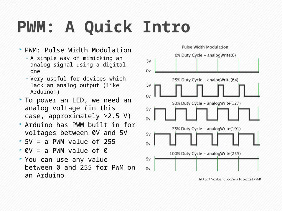
PWM: A Quick Intro PWM: Pulse Width Modulation
A simple way of mimicking an analog signal using a digital one
Very useful for devices which lack an analog output (like Arduino!)
To power an LED, we need an analog voltage (in this case, approximately >2.5 V)
Arduino has PWM built in for voltages between 0V and 5V
5V = a PWM value of 255 0V = a PWM value of 0 You can use any value
between 0 and 255 for PWM on an Arduino http://arduino.cc/en/Tutorial/PWM

LEDs are very sensitive to changes in current
The current in an LED varies exponentially with voltage, therefore small increases in voltage are potentially dangerous!
Resistors vary linearly with voltage Using a resistor in series with an LED will limit the current through the LED, minimizing the risk of damage
Why Do We Need Resistors?

A Blinking LED First Step:
Walk through the code step by step Second Step:
Learn how to download code to the Arduino Third Step:
Understand the hardware setup

//PART 1: Reading and running basic Arduino code
//Variable Declarationint LED = 3; //Define which port on the Arduino board will be usedint toggle = 0; //Setup a variable which turns the LED on and off
void setup() //All arduino programs have setup loops. This code runs before everything else. Put pin setup and communications setup code herepinMode(LED, OUTPUT); //Defining the port (or pin, interchangable) we decide upon as an output of the Arduino board
void loop() //Loops contain the majority of Arduino code, your main program will go within this structure.//The following logic flips our "toggle" variable between 0 and 255//As we learned in class, 255 is the maximum value for PWM ports on the Arduino board, meaning a PWM port set at 255 will output a constant 5 voltsif (toggle == 0)toggle = 255;else if (toggle == 255)toggle = 0;analogWrite(LED, toggle); //Here, we send the new value of toggle to the port LED (which we defined as port 3 on line 1).
delay(500); //Wait 500 milliseconds before restarting the loop; this way we get a flashing LED!//Make sure to close your brackets!

Connect the Arduino to your PC via the USB cable
Open the Arduino software (arduino.exe)
This is where you can write/edit your code It will tell you if there are
errors during compilation Press the check mark to
compile your code Press the right facing
arrow to download your code to the board
HW/SW Interaction

You may have to change the COM port through which the software and Arduino board communicate
Ask your GTA for help if there is any confusion
HW/SW Addendum
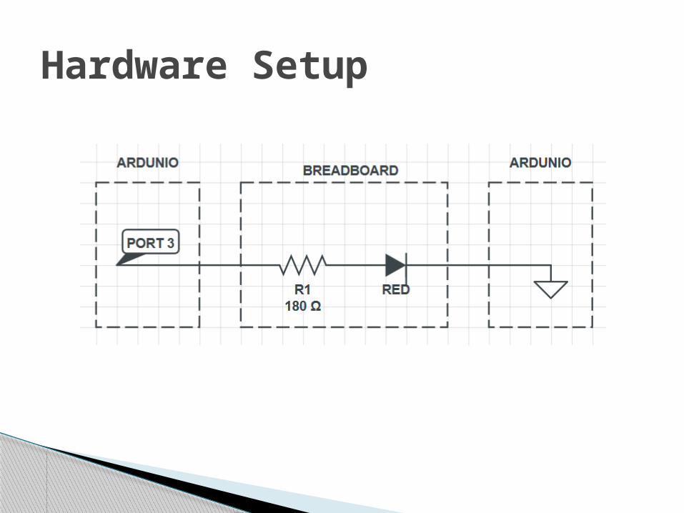
Hardware Setup
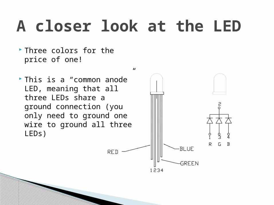
A closer look at the LED Three colors for the price
of one!
This is a “common anode” LED, meaning that all three LEDs share a ground connection (you only need to ground one wire to ground all three LEDs)

Hardware Setup (2)
PORT 3
GROUND

Check out an Arduino from your GTA and a USB cable from the lab techs
Build the device we just discussed
Don’t hesitate to ask when you have questions!
Next: using all three colors!
Now It’s Your Turn!

We want to make a device which features all three colors on the LED fading from dim to bright
You will be given the majority of the code for the code for the red and green LEDs; your assignment will be to add code to activate the blue LED as well.
First, build the circuit on the next slide and download the following code to your board to see what it does.
A Challenge: Using all three colors of the LED

Hardware Setup
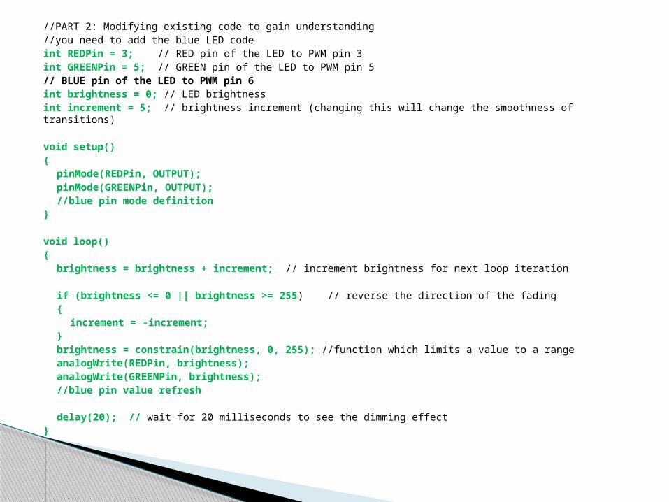
//PART 2: Modifying existing code to gain understanding//you need to add the blue LED codeint REDPin = 3; // RED pin of the LED to PWM pin 3int GREENPin = 5; // GREEN pin of the LED to PWM pin 5// BLUE pin of the LED to PWM pin 6int brightness = 0; // LED brightnessint increment = 5; // brightness increment (changing this will change the smoothness of transitions)
void setup()pinMode(REDPin, OUTPUT);pinMode(GREENPin, OUTPUT);//blue pin mode definition
void loop()brightness = brightness + increment; // increment brightness for next loop iteration
if (brightness <= 0 || brightness >= 255) // reverse the direction of the fadingincrement = -increment;brightness = constrain(brightness, 0, 255); //function which limits a value to a rangeanalogWrite(REDPin, brightness);analogWrite(GREENPin, brightness);//blue pin value refresh
delay(20); // wait for 20 milliseconds to see the dimming effect

Ask your GTA if anything is unclear.
When you finish, return your Arduino IN ITS BOX!
Add The Blue LED

http://arduino.cc
http://arduino.cc/en/Tutorial/HomePage
http://learn.adafruit.com/adalight-diy-ambient-tv-lighting
References