Embed Size (px)
Citation preview

1© 2021 Kai Sun
Spring 2021Instructor: Kai Sun
ECE 522 ‐ Power Systems Analysis IISpring 2021
Voltage Regulation and Control

2© 2021 Kai Sun
Content
• Modeling the excitation control system (AVR) of a generator• Influence on angular stability and power system stabilizer (PSS)• Reactive power compensation and control
• References:– Saadat’s Chapters 12.6-12.7– Kundur’s Chapters 5.4, 8 and 11.2– EPRI Tutorial’s Chapter 5
3© 2021 Kai Sun
Objectives of Voltage and Reactive Power Control
• Equipment security:– Voltages at terminals of all equipment (of either utility and customers) in the system are
within acceptable limits to avoid damage
• System stability:– System stability is enhanced to maximize utilization of the transmission system.
(Voltage and reactive power control have a significant impact on system stability.)
• Transmission efficiency:– The reactive power flow is minimized so as to reduce RI2 and XI2 losses to improve
transmission system efficiency, i.e. leaving the room mainly for real power transfer

4© 2021 Kai Sun
Reactive Power Transfers
• Reactive power flows from the high voltage side to the low voltage side.• But reactive power cannot be transmitted over long distances because
– it would require a large voltage gradient to do so, and– an increase in reactive power transfer causes an increase in Qloss as well as Ploss.
• The unit of reactive power isvar (volt-ampere reactive) although Var, VAR and Varare also used.
5© 2021 Kai Sun
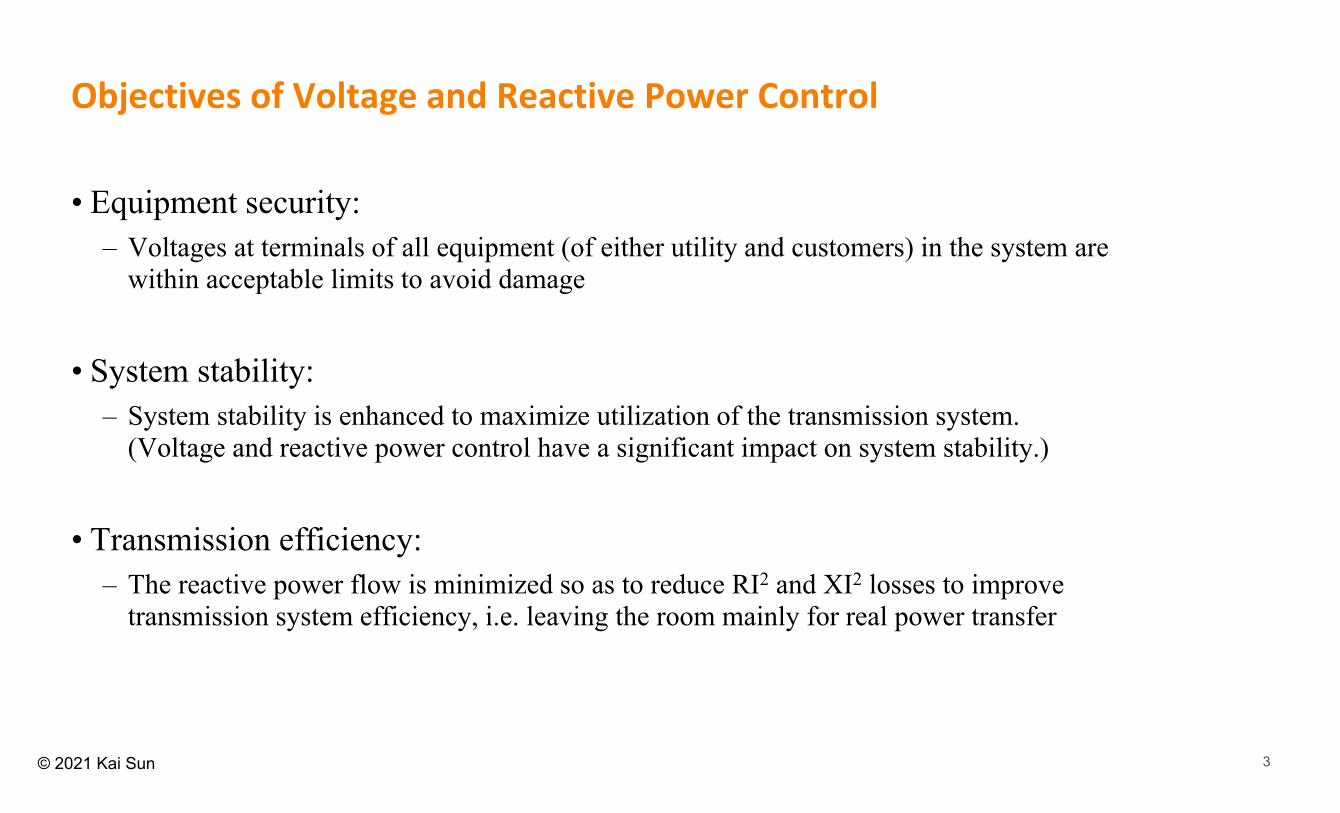
Methods of Reactive Power and Voltage Control
Equipment Supply Q Absorb Q
Synchronous generator
Overhead lines
Underground cables
Transformers
Loads
Compensating devices
Y(Over‐excited)
Y (Under‐excited)
Y Y
Mostly
Y
Mostly
Y Y
• Generators: – Excitation control systems with automatic
voltage regulators (AVRs)• Other control devices
– Sources or sinks of var, e.g. • shunt capacitors, • shunt reactors, • synchronous condensers, • static var compensators (SVC)
– Line reactance compensators, e.g. series capacitors
– Regulating transformers, e.g. tap-changing transformers and boosters.

6© 2021 Kai Sun
Excitation Systems of Generators
• The basic function of an excitation system is to provide direct current to the synchronous machine field winding.
• In addition, the automatic voltage regulator (AVR) with an excitation system performs control and protective functions essential to the satisfactory performance of the power system by controlling the field voltage and thereby the field current.
Field current

7© 2021 Kai Sun
Performance Requirements of Excitation Systems
• On the generator:– Under steady-state conditions, the excitation system should supply and automatically adjust
the field current of the synchronous generator to maintain the terminal voltage as the output varies continuously within the capacity of the generator.
– Under disturbances, the excitation system must be able to respond to transient disturbances with field forcing consistent with the generator instantaneous and short-term capacities
– In either case, heating limits (e.g. due to resistances that carry It or ifd) should be concerned.
• On the power system– The excitation system should contribute to effective control of voltage and enhancement of
system stability under both large and small disturbances.
8© 2021 Kai Sun
cos
sin
t
t
t
t
P E
Q E
I
I
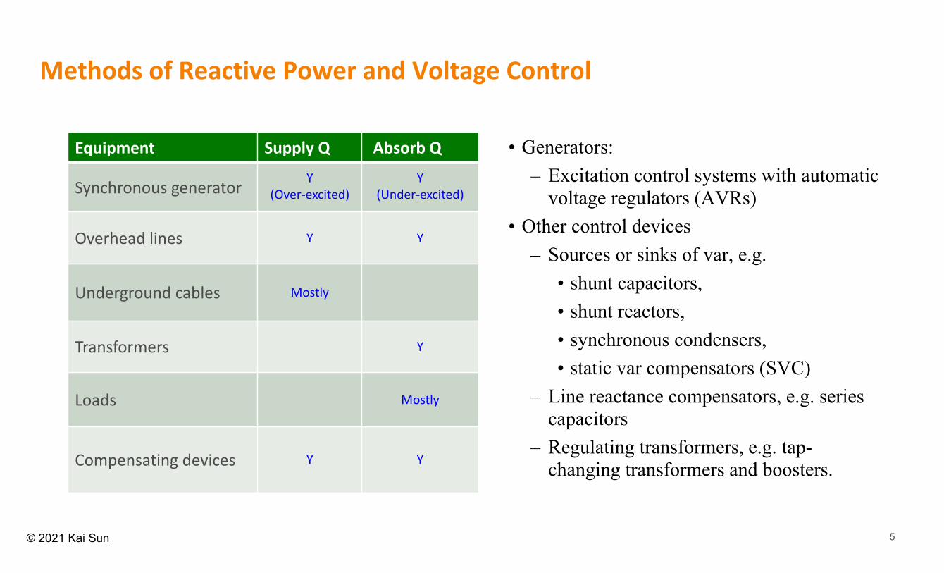
End region heating limit (due to heating caused by end-turn flux in under-excited conditions)
Over-excited(Supplying Q, Lagging p.f.)
Under-excited(Absorbing Q, Leading p.f.)
Under-excited Limit
It<It,max : Armature current heating limit
ifd<ifd, max: Field current heating limit
>0 (over-excited)
<0 (under-excited)
Reactive Power Capacity of a Generator
Ignore Ra
D‐curve
“D-curve”
It,max
ifd, max
EqifdXad
2
sin
cos
adt i
s
ad tt i
s s
fd
fd
i
i
XEX
X EEX X
Always >0
9© 2021 Kai Sun
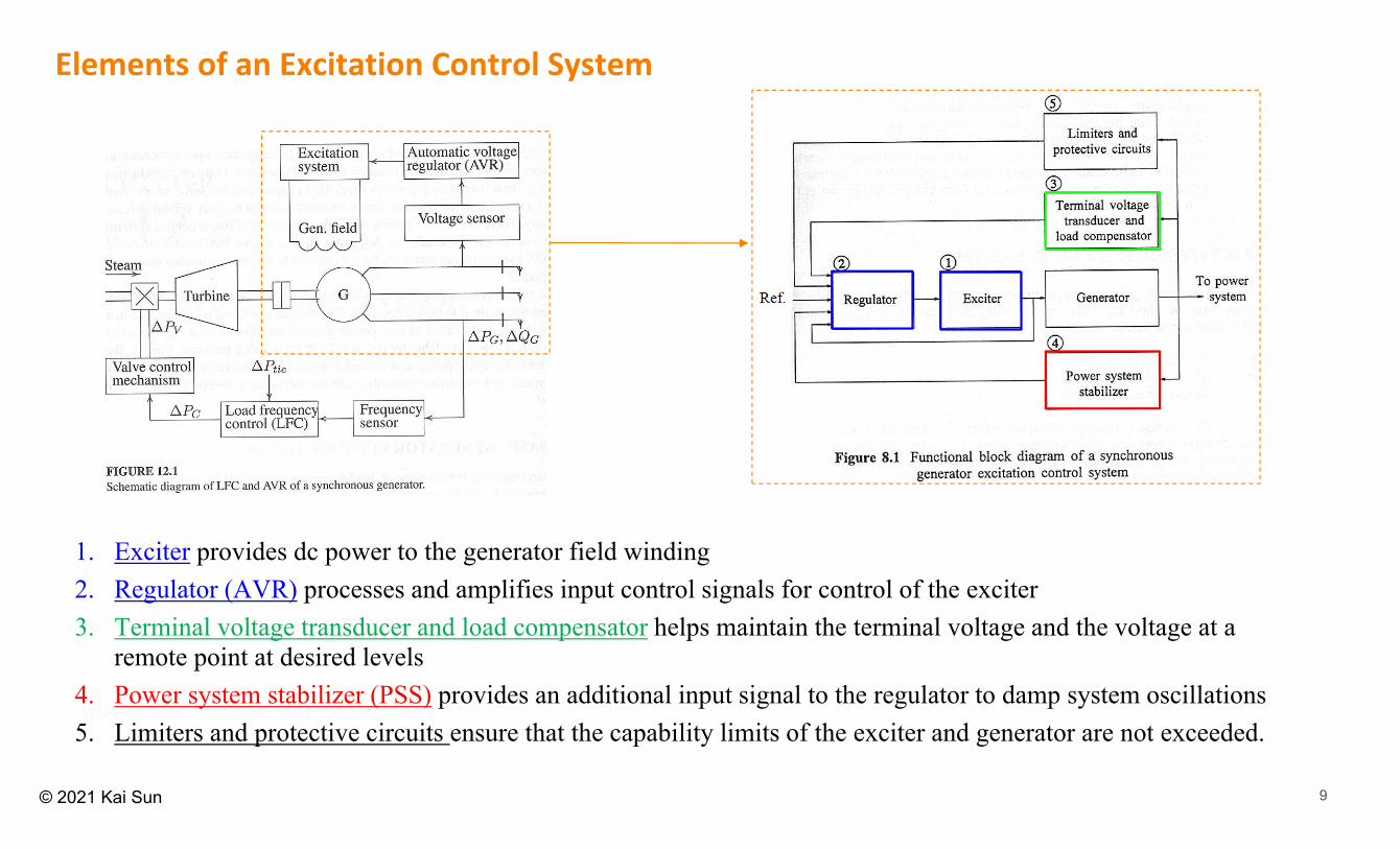
Elements of an Excitation Control System
1. Exciter provides dc power to the generator field winding2. Regulator (AVR) processes and amplifies input control signals for control of the exciter3. Terminal voltage transducer and load compensator helps maintain the terminal voltage and the voltage at a
remote point at desired levels4. Power system stabilizer (PSS) provides an additional input signal to the regulator to damp system oscillations5. Limiters and protective circuits ensure that the capability limits of the exciter and generator are not exceeded.

10© 2021 Kai Sun
• Simplified linear model (ignoring saturations with the amplifier and exciter and other nonlinearities:
– Rectifier/Sensor model: • R is very small, e.g. 0.01 to 0.06s
– Amplifier model: • KA=10 to 400, A=0.02 to 0.1s
– Exciter model:• E is very small for modern exciters
– Generator model: • KG=0.7 to 1.0, G=1.0 to a few seconds
from full load to no-load
Excitation Control System/AVR Model
What is G?
( )( )
d
fd
s se s
𝛥𝑉 𝑠𝛥𝑉 𝑠 ~
s
11© 2021 Kai Sun
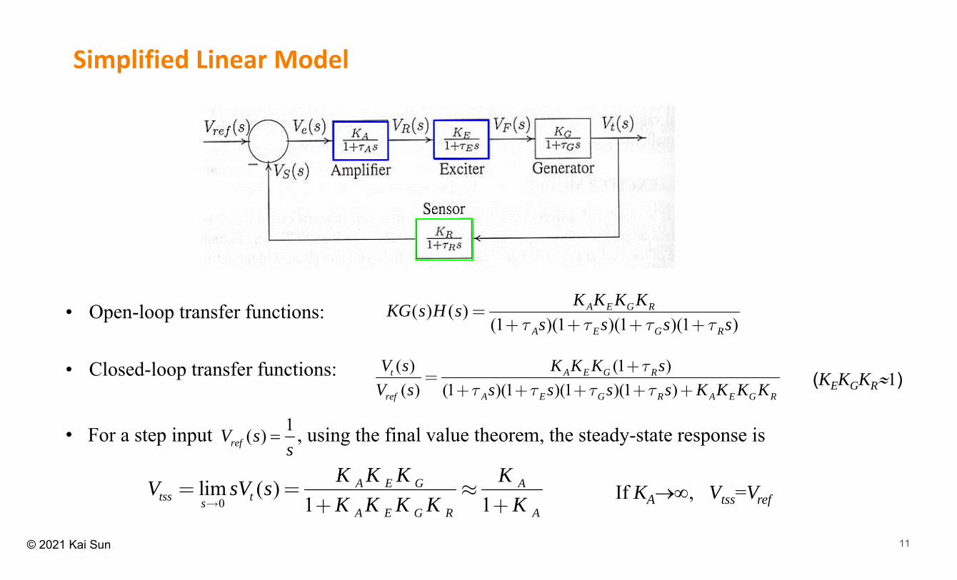
• For a step input , using the final value theorem, the steady-state response is
• Open-loop transfer functions:
• Closed-loop transfer functions:
Simplified Linear Model
( ) ( )(1 )(1 )(1 )(1 )
A E G R
A E G R
K K K KKG s H ss s s st t t t
=+ + + +
( ) (1 )( ) (1 )(1 )(1 )(1 )
t A E G R
ref A E G R A E G R
V s K K K sV s s s s s K K K K
tt t t t
+=
+ + + + +
0lim ( )
1 1A E G A
tss tsA E G R A
K K K KV sV sK K K K K
= = »+ +
1( )refV ss
(KEKGKR1)
If KA, Vtss=Vref

12© 2021 Kai Sun
Saadat’s Example 12.6

13© 2021 Kai Sun
-20 -15 -10 -5 0-10
-8
-6
-4
-2
0
2
4
6
8
10Root Locus
Real Axis (seconds-1)
Imag
inar
y A
xis
(sec
onds
-1)
• KA=10, Vtss=0.909Vref
• KA=12.16, Vtss=0.924Vref
0 5 10 15 200
0.2
0.4
0.6
0.8
1
1.2
1.4
1.6
1.8
t, s
Terminal voltage step response
0 5 10 15 200
0.2
0.4
0.6
0.8
1
1.2
1.4
1.6
1.8
2
t, s
Terminal voltage step response
• KA=5, Vtss=0.833Vref
0 5 10 15 200
0.2
0.4
0.6
0.8
1
1.2
1.4
t, s
Terminal voltage step response
-1/A-1/R -1/E -1/G
KA=12.16
500( ) ( )(1 )(1 )(1 )(1 ) ( 20)( 10)( 2.5)( 1)
A E G R A
R A E G
K K K K KKG s H ss s s s s s s st t t t
= =+ + + + + + + +

14© 2021 Kai Sun
• It has two conjugate complex roots and its zero-input response is a damped sinusoidal oscillation:
21 2, 1n ns s j js w zw w z= =- -
Harmonic oscillator
2 22 n ns szw w+ + = – Damping ratio
n – Natural frequency
2
( ) sin( )
sin( 1 )n
t
tn
x t Ae t
Ae t
s
zw
w j
w z j-
= +
= - +
11/n
The time of decaying to 1/e=36.8%:
s1
s2
2 0D Ks sM M
+ + =F M x K x D x = ⋅ =- ⋅ - ⋅
1 2( )( ) 0s s s s- - =

15© 2021 Kai Sun
Excitation System Stabilizers
• Rate feedback
• PID control (sim12ex8.mdl)
t, s
Terminal voltage step response
KA=10
KF=0.2 TF=0.02
KP=1 KI=0.25 KD=0.28

16© 2021 Kai Sun
Stabilizer Design for AVR• See Example 7.8 in Anderson’s “Power System Control and Stability” for details on choosing KF and F
The stabilizer adds a new pole at –1/F
F>1
0.05<F<1
F< 0.05

17© 2021 Kai Sun
Non‐reciprocal per unit system• Lad-base Reciprocal per unit system: armature terminal voltage Et is
around 1.0 pu under normal operating conditions, but exciter output voltage efd (i.e. field voltage) in pu is very small (~0.001 pu)
• Non-reciprocal per unit system, as an alternative:– 1 pu field voltage Efd produces rated armature terminal voltage Et on
the air-gap line– 1 pu field current Ifd corresponds to rated field current ifd
See Example 8.1:
Rfd=0.0006 pu, Ladu=1.66 pu
ifd=1.565 pu, efd = 0.000939 pu
Ifd=2.598 pu, Efd=2.598 pu

18© 2021 Kai Sun
Detailed excitation system model with load compensation
With positive (or negative) RC and XC, the voltage at a point within (or outside) the generator is regulated.
VR Efd
Et
It
RC+jXC VC1AVR

19© 2021 Kai Sun
Separately excited DC Exciter (DC generator)
Main generatorDC Exciter
VR=Eef VR=Eef -EX
( )( )ef ef ef efX X
ef ef ef ef X e X efg g
d L I L d IE dEE R I R E S E Ldt R R dt dt
æ ö D÷ç ÷ç= + = + + +÷ç ÷÷çè ø
( )X Xef ef X e X
g g
E EI I E S ER R
= +D = +
( ) Xef E X X e X E
dEE K E E S E Tdt
+ +

20© 2021 Kai Sun
IEEE Type DC2A Excitation System Model: ESDC2A
From PSS
(VUEL - Under-excitation limiter output)
(Taking the bigger input)
Voltage transducer
VR Efd

21© 2021 Kai Sun
AC Exciter (Brushless Excitation)
• Electronic rectifiers replace the commutator, slip-rings and brushes
AC exciter Main generator

22© 2021 Kai Sun
IEEE Type AC2A Excitation System Model: ESAC2A
Rectifier regulation
model

23© 2021 Kai Sun
• Constant field voltage Efd (KA=0):KD>0KS=KS(gen & network) + KS (fd)>0 or <0
Te= TS + TD
KS + KDr
Influence of excitation control on angular stability2
20
2 ( , )m e r m eH d T T T T
dt
• KS = KS(fd) +KS(gen & network)
KD = KD (fd) +KD(gen & network)
Usually, KS (gen & network)>0, KD (gen & network)>0
• With excitation control (large KA)KS>0KD =KD(gen & network) + KD (fd) >0 or <0
24© 2021 Kai Sun
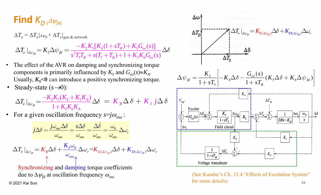
• For a given oscillation frequency s=josc :
R IK K jd d= D + D
0oscr
osc osc osc osc
j sjw d wd d
d ww w w w
D D DD = = = = D
Synchronizing and damping torque coefficients due to fd at oscillation frequency osc
• The effect of the AVR on damping and synchronizing torque components is primarily influenced by K5 and Gex(s)KA. Usually, K5<0 can introduce a positive synchronizing torque.
(See Kundur’s Ch. 12.4 “Effects of Excitation System” for more details)
34 5 6
3
( ) ( )1 1
exfd fd
R
K G sK K KsT sT
y d d yé ùê úD = - D - D + Dê ú+ +ë û
2 3 4 52
3 62
3 3
| [ (1 ) ( )]( ) 1 ( )fd
R ex
R R ee
xfd
K K K sT K G ss T T s T T K G s
TK
Ky y dDD- +
+= D
++ +
= D+
2 3 4 5
3 6
( )1
|fd
A
Ae
K K K K KK K K
T y dD
- ++
D = D
0( )( )| =
fdd fdfe r rs
R SI
Do c
K KK KT yy y
wd w d w
w DDDD = D + D D + D
• Steady-state (s0):
Find KD (fd)
( )( )|ffd fdde rS DKKT yy yd wDD DD = D + D
Te = Te|fd + Te|gen & network

25© 2021 Kai Sun
Example on effects of different AVR settings
• Steady-state synchronizing torque coefficient:The effect of the AVR is to increase the synchronizing torque component at the steady state
• Damping and synchronizing torque components at rotor oscillation frequency 10 rad/s (fosc=1.59Hz, s=josc=j10)
26© 2021 Kai Sun
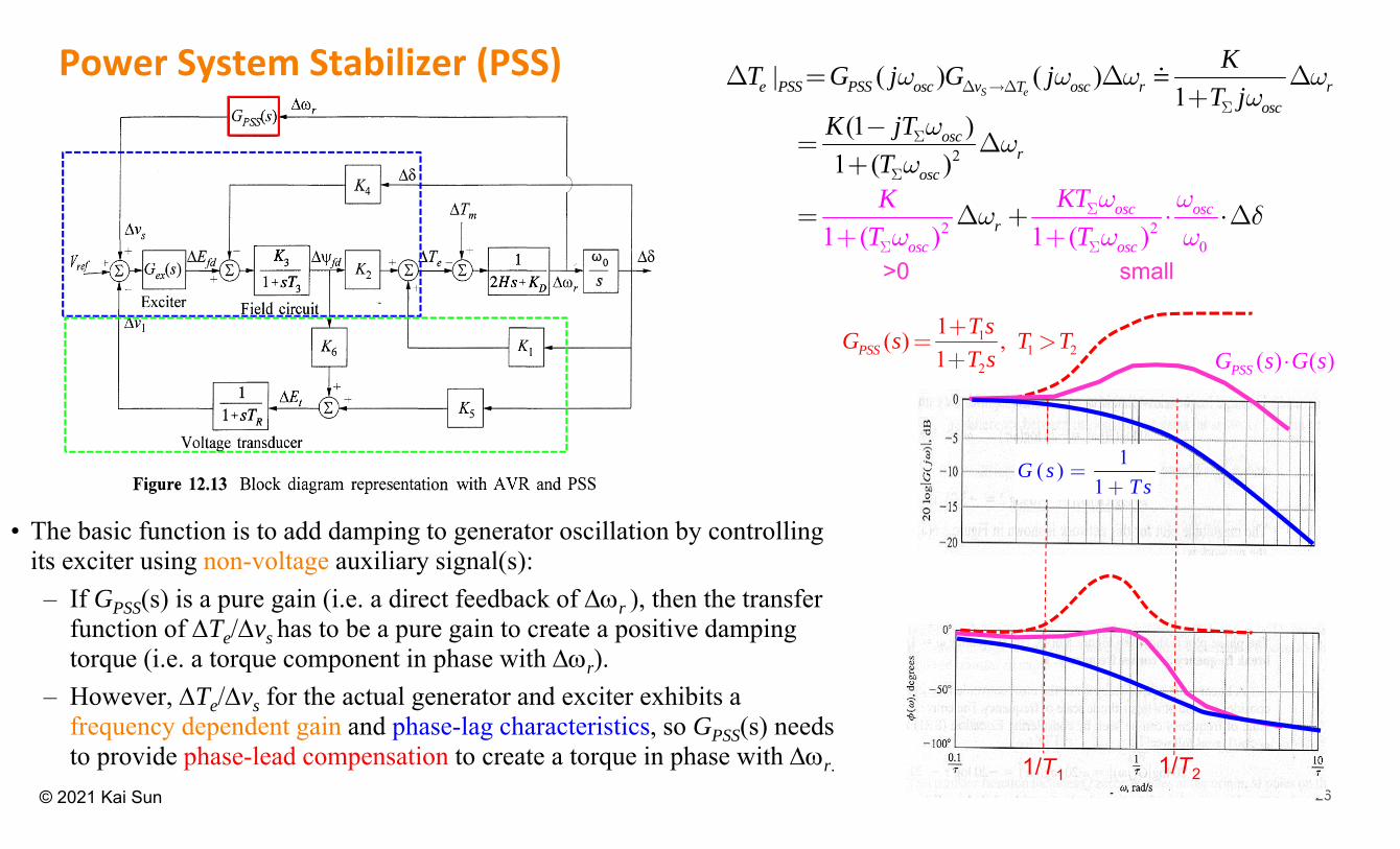
• The basic function is to add damping to generator oscillation by controlling its exciter using non-voltage auxiliary signal(s): – If GPSS(s) is a pure gain (i.e. a direct feedback of r ), then the transfer
function of Te/vs has to be a pure gain to create a positive damping torque (i.e. a torque component in phase with r).
– However, Te/vs for the actual generator and exciter exhibits a frequency dependent gain and phase-lag characteristics, so GPSS(s) needs to provide phase-lead compensation to create a torque in phase with r.
Power System Stabilizer (PSS)
11 2
2
1( ) , 1PSS
T sG s T TT s
+= >
+
1/T1 1/T2
1( )1
G sTs
=+
( ) ( )PSSG s G s⋅
| ( ) ( )1S ee PSS PSS osc v T osc r r
osc
KT G j G jT j
w w w wwD D
S
D = D D+
2
(1 )1 ( )
oscr
osc
K jTT
ww
wS
S
-= D
+
2 201 ( ) 1 ( )
osc osc
osc or
sc
KTKT T
w dw w
w w wS
S S
= ⋅++ +
D ⋅D
>0 small

27© 2021 Kai Sun
PSS Model
• Stabilizer gain KSTAB
– determines the amount of damping introduced by PSS• Signal washout block:
– High-pass filter with TW long enough (typically 1 to 20s) to allow signals associated with oscillations in r to pass unchanged. However, if it is too long, steady changes in speed would cause generator voltage excursions
• Phase compensation block:– Provides phase-lead compensation over the frequency range of interest (typically, f=0.1 Hz to 2.0 Hz, i.e. =0.6 to
12.6 rad/s)– Two or more first-order blocks, or even second-order blocks may be used. – Generally, some under-compensation is desirable so that the PSS results in a slight increase of the synchronizing
torque (a positive projection on axis) as well
(W=0.1rad/s 0.016Hz)
(osc1=2.5rad/s 0.4Hz)
(osc2=25rad/s 4.0Hz)
0.4Hz - 4Hz0.016Hz
TW=10s
T1=0.4s
T2=0.04s
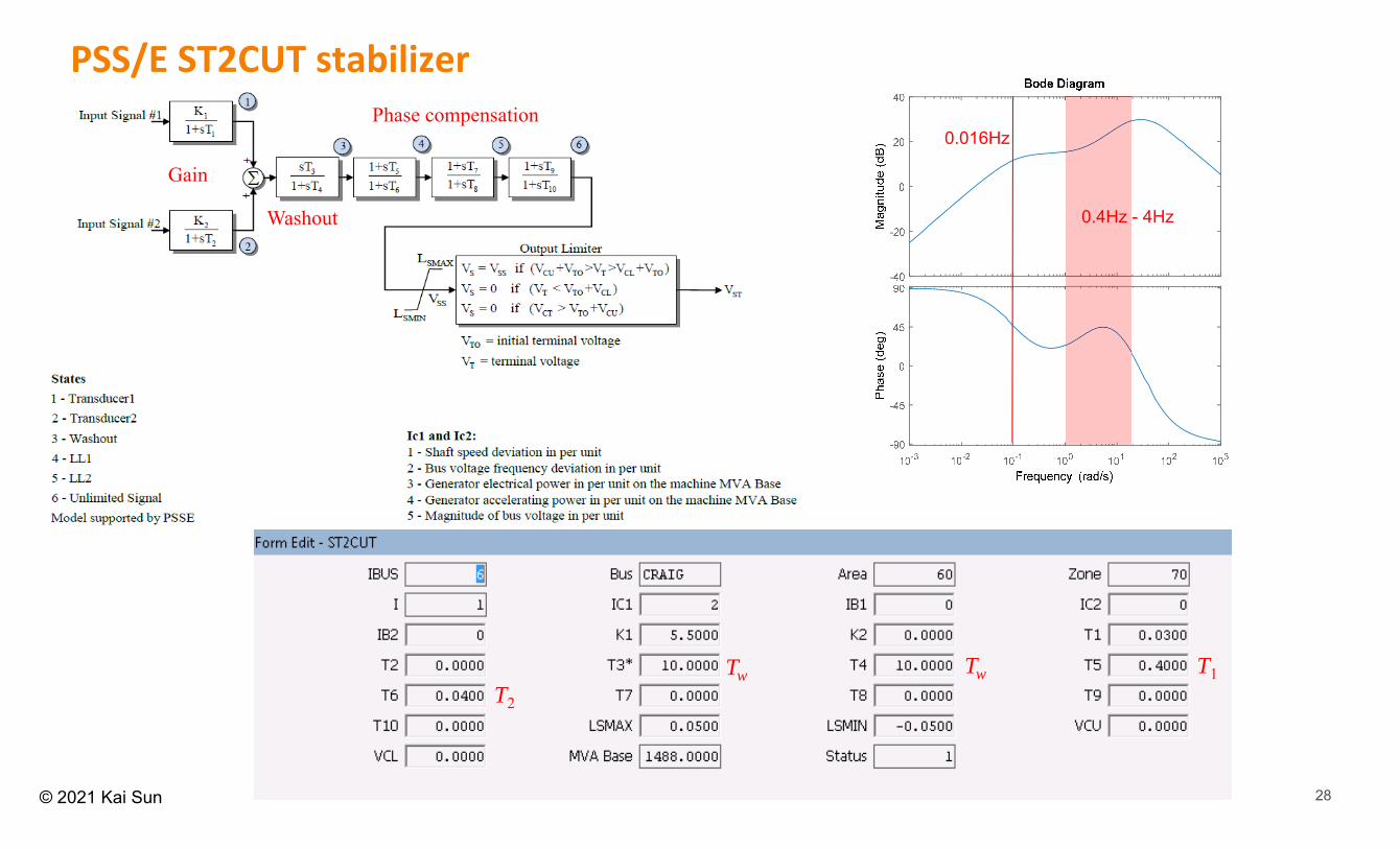
28© 2021 Kai Sun
PSS/E ST2CUT stabilizer
Tw Tw T1T2
Washout
Gain
Phase compensation
0.4Hz - 4Hz
0.016Hz

29© 2021 Kai Sun
Use of Other Voltage Control Equipment
• Passive: designed to be a permanent part of the system (fixed) or be switched in and out of service via circuit breakers or switchers– Shunt capacitors: supply Mvar (proportional to V2) to the system at a location and increase voltages near
that location.– Shunt reactors: absorb excessive Mvar from the system at a location and reduce voltages near that
location.– Series capacitors: reduce the impedance of the path by adding capacitive reactance (pro: self-regulating;
con: causing sub-synchronous resonance)– Series reactors: increase the impedance of the path by adding inductive reactance.
• Active (maintaining voltage levels at specific buses)– Tap Changing Transformers– Synchronous condensers– Static Var Systems, e.g. SVC and STATCOM, often referred to as FACTS (Flexible AC Transmission
Systems)

30© 2021 Kai Sun
Shunt Capacitors
• When a switchable shunt capacitor is switched in, the local voltage rises
• Shunt capacitor switching is often used to control normal daily fluctuations in system voltage levels due to load changes
• Locations:– Distribution systems: typically close to large customers to supply Mvar needs (so called power-factor
correction); placed at appropriate locations along the length of a feeder to ensure that voltages at all points remain within the allowable limits as the loads vary (so called feeder voltage control)
– Transmission systems: at transmission substations to support the Mvar needs of the bulk power system and maintain voltage levels during heavy loading conditions
• Advantage: Low cost and flexibility of installation and operation• Disadvantage: Mvar output Q =V2/XC, and is hence reduced at low voltages when it is likely to be needed most.
– e.g., if a 25 Mvar shunt capacitor rated at 115 kV is operated at 109 kV (V=0.95pu), its actual output is 22.5 Mvar, i.e. 90% of the rated value (Q=0.952=0.90pu).

31© 2021 Kai Sun
Series Capacitors• Connected in series with the line conductors to
compensate for the inductive reactance of the line.• Increasing the transmitted maximum power and
reduce the effective reactive power loss (XI2), while contributing to improved voltage control
• Advantage:– “Self-regulating” nature: unlike a shunt capacitor, series
capacitors produce more reactive power (output Q=XCI2) under heavier power flows
• Disadvantage: – Sub-synchronous resonance (SSR) is often caused by the
series-resonant circuit
e.g. fSSR=19Hz if XC=0.1XL (i.e. 10% series compensation)
01
2C
SSRL
Xf fXLCp
= =

32© 2021 Kai Sun
Use of Reactors• Series reactors: the primary use is to limit fault current• Shunt reactors
– Used to compensate for the overvoltage effects of line capacitance to limit voltage rise on open circuit or light load (see EPRI’s Ch-5.3 or Kundur’s 6.1 for causes of high voltage)
– Usually required for long EHV lines – Connected either to the tertiary windings of transformers or to EHV buses – During heavy loading conditions, some of shunt reactors may have to be disconnected.
( )CLZC
Surge impedance (real number):
If a power line supports its Surge Impedance Load (SIL), i.e. with load impedance equal to ZC, then PF=1 everywhere along the line.
• Load >>SIL: a shunt capacitor is often needed at the receiving end to reduce voltage drop.
• Load <<SIL: a shunt reactor is often needed at the receiving end to avoid over voltage.

33© 2021 Kai Sun
Use of Tap Changing Transformers• A tap changer control the voltage of a transformer’s winding by adjusting the number of turns in the winding. • Off-load tap changer (OLTC): mechanical linkages within the primary or secondary windings; can only be adjusted
when the transformer current flow has been completely interrupted.• Under-load tap changer (ULTC): designed to change tap positions while the transformer is carrying load current.• ULTCs can be operated in either a manual or an automatic mode. When in an automatic mode, the ULTCs
automatically respond to system conditions and adjust tap positions.• ULTCs may control a remote secondary voltage (no at its physical location)
Voltage regulating relayLoad drop
compensation

34© 2021 Kai Sun
Concerns of Using Tap Changing Transformers• Normally, when the turns ratio is adjusted, the Mvar flow across the transformer is also adjusted• However since a transformer absorbs Mvar to build its internal magnetic field, when its secondary voltage is
raised via a tap change, its Mvar usage increases and its primary voltage often drops. The greater the tap change and the weaker the primary side, the greater the primary voltage drop.
• If the primary side is weak, the tap change may not necessarily increase the secondary voltage. Therefore, spare Mvar must be available for a tap change to be successful.
(5/16x10%= +3.125% ~ 142.3kV)
(+10% ~ 151.8kV)
An example:
10% / 33-position ULTC
(Neutral point: 0% ~ 138kV)

35© 2021 Kai Sun
Use of Synchronous Condensers
• Synchronous machines running as synchronous motors without a prime mover. The power system supplies MW to turn the rotor.
• By controlling the field excitation, it can be made to either generate or absorb Mvar.• Often connected to the tertiary windings of transformers.• Expensive Mvar source, seldom used in modern power systems.• However, some companies use them to support Mvar and increase inertia by their spinning mass.• Some synchronous generators can be operated in a motoring mode when MW is not required
from the generators, such as– Some hydro units in light load conditions,– Some combustion turbine peaking units (by disconnecting the turbine from the generator).

36© 2021 Kai Sun
Use of Static Var Compensators (SVC)
• “Static” (no rotating parts); supply or absorb Mvar• Typically, a SVC is composed of
– shunt reactors and capacitors– high speed thyristor switches used to adjust the
amount of reactors or capacitors in-service at any one time
– a control system (similar to AVR) to maintain a target voltage level
• If the bus voltage dips below the target value, the control system can control thyristors to reduce reactor current flow or to switch more capacitors in service, such as to raise the bus voltage
TCR - Thyristor-controlled reactorTSC - Thyristor-switched capacitorHP filer - High-pass filter to absorb high frequency
harmonics caused by thyristor switches

37© 2021 Kai Sun
Static Var Systems (SVS)
• A SVS is an aggregation of SVCs and mechanically switched capacitors (MSCs) or reactors (MSRs) whose outputs are coordinated.
• A simple example of an SVS is one SVC combined with local ULTCs.
See Kundur’s Pages 640-645
38© 2021 Kai Sun
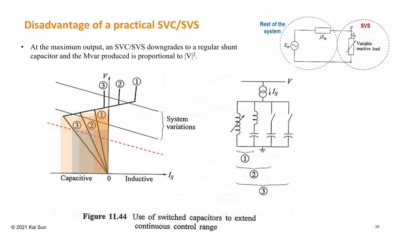
• At the maximum output, an SVC/SVS downgrades to a regular shunt capacitor and the Mvar produced is proportional to |V|2.
Disadvantage of a practical SVC/SVS

39© 2021 Kai Sun
Use of STATCOM• Similar to synchronous condenser, STATCOM (static synchronous compensator)
has an internal voltage source which provides constant output current even at very low voltages. Therefore, its Mvar output is linearly proportional to |V|.
• The voltage-sourced converter (VSC) converts the dc voltage into a three-phase set of output voltages with desired amplitude, frequency, and phase.
Indu
ctio
n m
otor
term
inal
vol
tage
(pu)
Time (sec)0.00 2.00 4.00 6.00 8.00 10.00
0.00
0.24
0.48
0.72
0.96
1.20
0.00 2.00 4.00 6.00 8.00 10.000.00
0.72
0.
6.00
Without VAr
With SVC
With STATCOM
B. Sapkota, et al, "Dynamic VAR planning in a large power system using trajectory sensitivities,” IEEE Trans. Power Systems, 2010.

40© 2021 Kai Sun
FIDVR (Fault‐Induced Delayed Voltage Recovery)
NERC/WECC Planning standards require that following a single contingency,
• Voltage dip should not exceed 25% at load buses or 30% at non-load buses
• Voltage dip should not exceed 20% for more than 20 cycles at load buses
• Post-transient voltage deviation not exceed 5% at any bus
In some literature, FIDVR is also called “transient voltage stability” (an old term discouraged by IEEE PES from 2021)


![Untitled-1 [] 522 Plaster.pdf · Cizallas para vendajes enyesados BERGMANN 522-100 ESMARCH 522-110 20.0 cm 522-112 22.0 cm SEIJTIN 522-130 23.0 cm STILLE 522-140 24.0 cm STILLE 522-150](https://img.pdfslide.net/doc/110x75/60243f2763d73b35317c25cf/untitled-1-522-plasterpdf-cizallas-para-vendajes-enyesados-bergmann-522-100.jpg)