Embed Size (px)
Citation preview
1
ECE1311 Electric Circuits
Chapter 10
Sinusoidal Steady-State Analysis
Copyright © The McGraw-Hill Companies, Inc. Permission required for reproduction or display.
2
Sinusoidal Steady-State Analysis Chapter 10
10.1 Basic Approach
10.2 Nodal Analysis
10.3 Mesh Analysis
10.4 Superposition Theorem
10.5 Source Transformation
10.6 Thevenin and Norton Equivalent Circuits
3
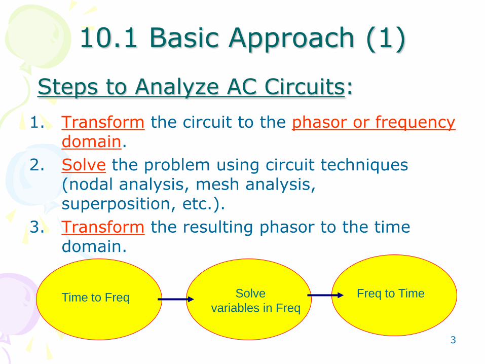
Steps to Analyze AC Circuits:
1. Transform the circuit to the phasor or frequency domain.
2. Solve the problem using circuit techniques (nodal analysis, mesh analysis, superposition, etc.).
3. Transform the resulting phasor to the time domain.
Time to Freq Solve
variables in Freq
Freq to Time
10.1 Basic Approach (1)
4
10.2 Nodal Analysis (1)
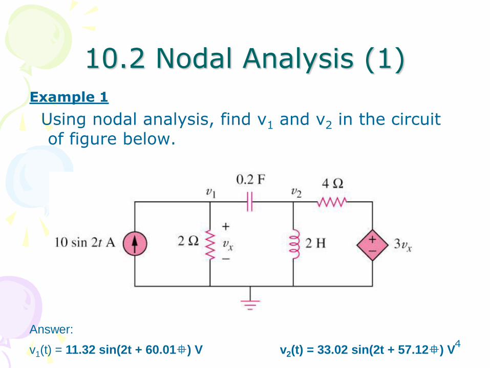
Example 1
Using nodal analysis, find v1 and v2 in the circuit of figure below.
v1(t) = 11.32 sin(2t + 60.01) V v2(t) = 33.02 sin(2t + 57.12) V
Answer:
5
10.3 Mesh Analysis (1)
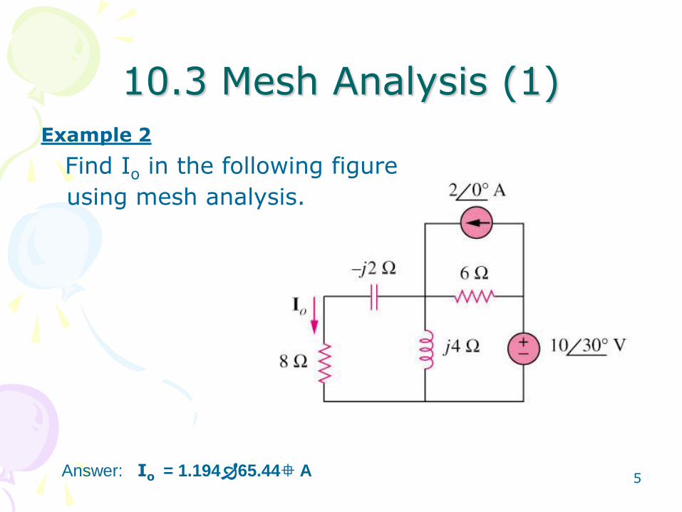
Example 2
Find Io in the following figure
using mesh analysis.
Answer: Io = 1.19465.44 A
6
10.4 Superposition Theorem (1)
When a circuit has sources operating at
different frequencies,
• The separate phasor circuit for each frequency must be solved independently, and
• The total response is the sum of time-domain responses of all the individual phasor circuits.
7
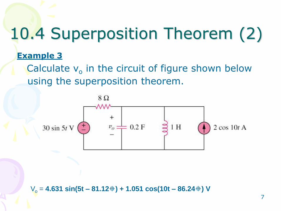
10.4 Superposition Theorem (2)
Example 3
Calculate vo in the circuit of figure shown below
using the superposition theorem.
Vo = 4.631 sin(5t – 81.12) + 1.051 cos(10t – 86.24) V
8
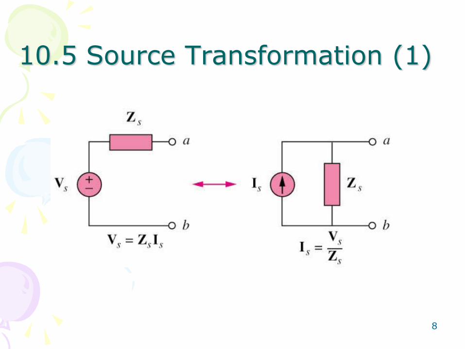
10.5 Source Transformation (1)
9
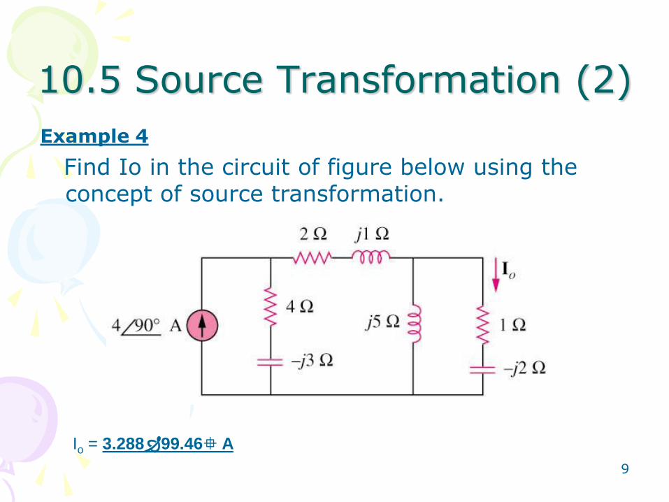
10.5 Source Transformation (2)
Example 4
Find Io in the circuit of figure below using the concept of source transformation.
Io = 3.28899.46 A
10
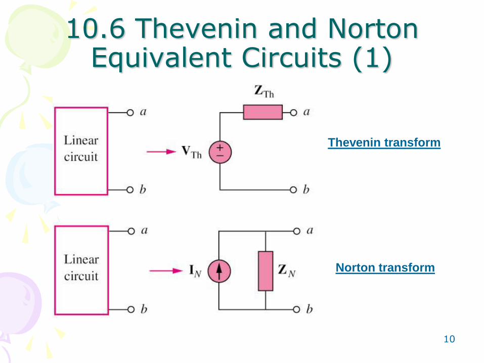
10.6 Thevenin and Norton Equivalent Circuits (1)
Thevenin transform
Norton transform
11
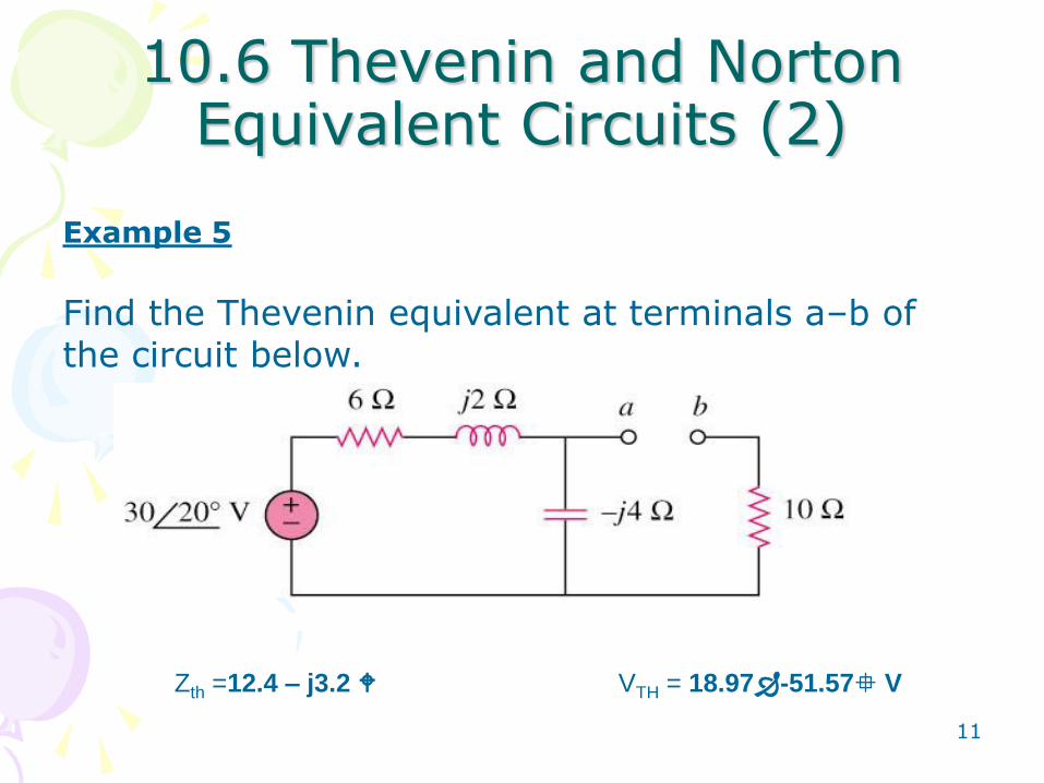
10.6 Thevenin and Norton Equivalent Circuits (2)
Example 5
Find the Thevenin equivalent at terminals a–b of the circuit below.
Zth =12.4 – j3.2 VTH = 18.97-51.57 V