Embed Size (px)
Citation preview
ECE 448 – FPGA and ASIC Design with VHDL
Lecture 14
PicoBlaze Instruction Set
2 ECE 448 – FPGA and ASIC Design with VHDL
Required reading
• P. Chu, FPGA Prototyping by VHDL Examples Chapter 15 PicoBlaze Assembly Code Development
Recommended reading
• K. Chapman, PicoBlaze for Spartan-6, Virtex-6, and 7-Series (KCPSM6)
3
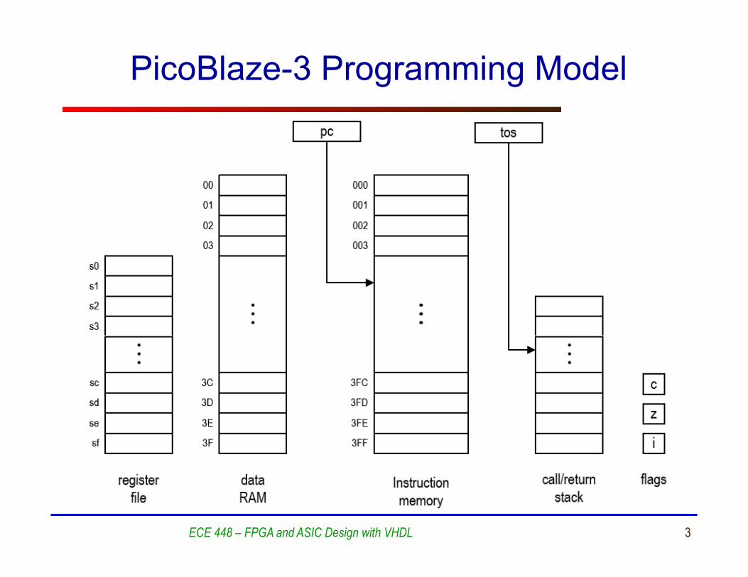
PicoBlaze-3 Programming Model
ECE 448 – FPGA and ASIC Design with VHDL
4
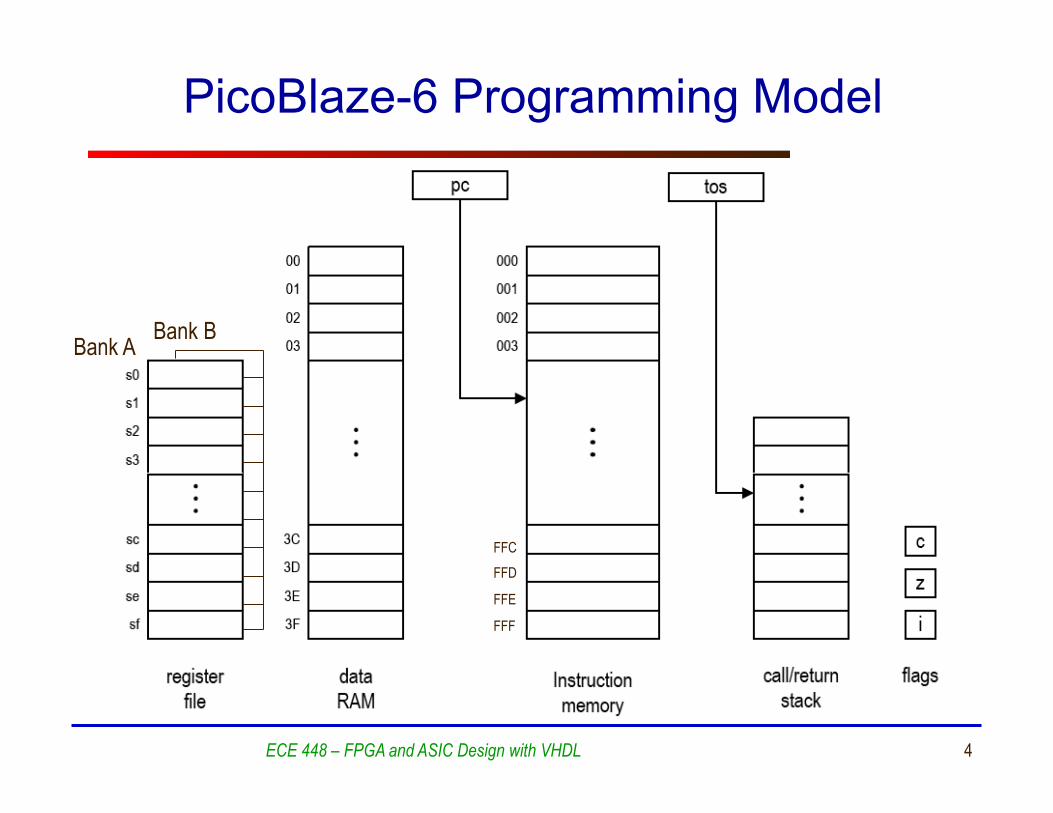
PicoBlaze-6 Programming Model
ECE 448 – FPGA and ASIC Design with VHDL
FFC FFD
FFE
FFF
Bank A Bank B
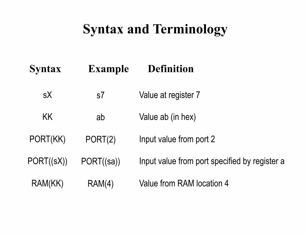
Syntax and Terminology
Syntax Example Definition
sX
KK
PORT(KK)
PORT((sX))
RAM(KK)
s7
ab
PORT(2)
PORT((sa))
RAM(4)
Value at register 7
Value ab (in hex)
Input value from port 2
Input value from port specified by register a
Value from RAM location 4
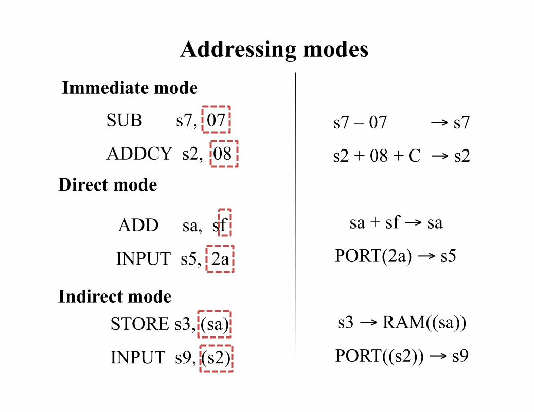
Addressing modes
Direct mode
ADD sa, sf
INPUT s5, 2a
sa + sf → sa
PORT(2a) → s5
Indirect mode STORE s3, (sa)
INPUT s9, (s2)
s3 → RAM((sa))
PORT((s2)) → s9
s7 – 07 → s7
s2 + 08 + C → s2
Immediate mode
SUB s7, 07
ADDCY s2, 08
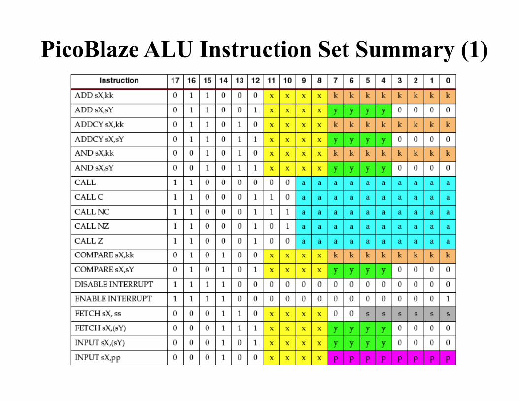
PicoBlaze ALU Instruction Set Summary (1)
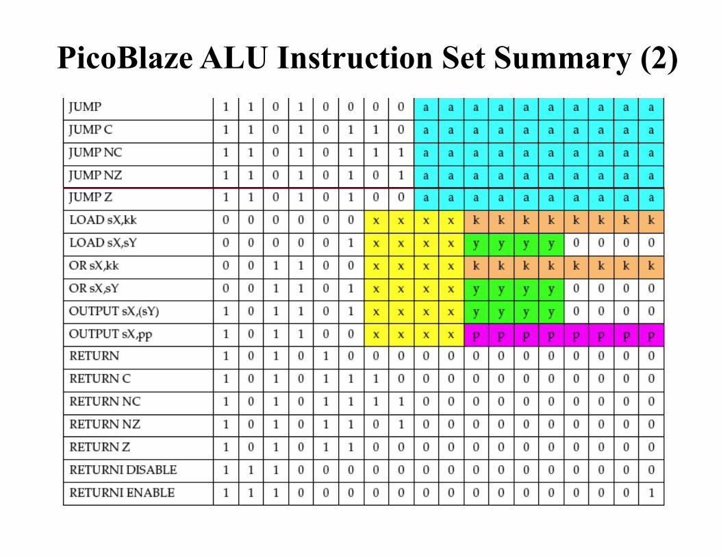
PicoBlaze ALU Instruction Set Summary (2)
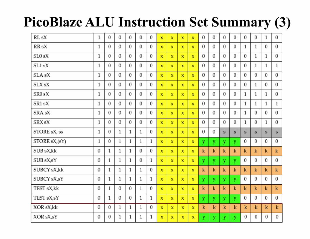
PicoBlaze ALU Instruction Set Summary (3)
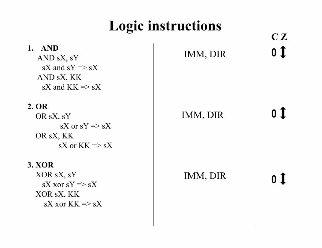
Logic instructions
1. AND AND sX, sY
sX and sY => sX AND sX, KK
sX and KK => sX
2. OR OR sX, sY
sX or sY => sX OR sX, KK
sX or KK => sX
3. XOR XOR sX, sY
sX xor sY => sX XOR sX, KK
sX xor KK => sX
IMM, DIR
C Z
IMM, DIR
IMM, DIR
0
0
0
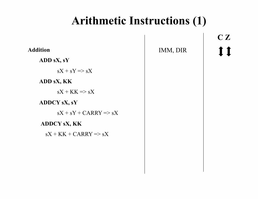
Arithmetic Instructions (1)
IMM, DIR
C Z Addition
ADD sX, sY
sX + sY => sX
ADD sX, KK
sX + KK => sX
ADDCY sX, sY
sX + sY + CARRY => sX
ADDCY sX, KK
sX + KK + CARRY => sX
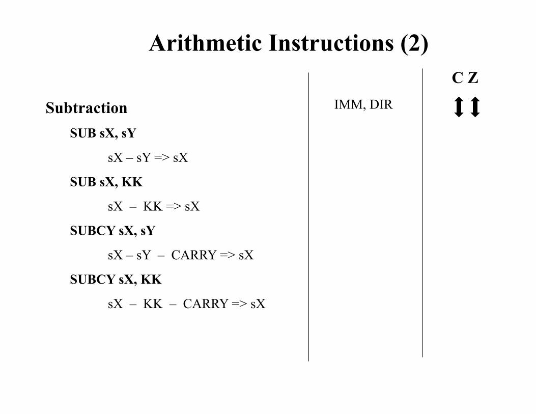
Arithmetic Instructions (2)
Subtraction SUB sX, sY
sX – sY => sX
SUB sX, KK
sX – KK => sX
SUBCY sX, sY
sX – sY – CARRY => sX
SUBCY sX, KK
sX – KK – CARRY => sX
IMM, DIR
C Z
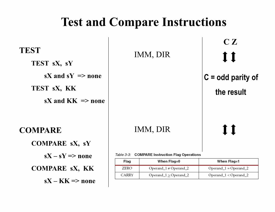
Test and Compare Instructions
TEST TEST sX, sY
sX and sY => none
TEST sX, KK
sX and KK => none
COMPARE COMPARE sX, sY
sX – sY => none
COMPARE sX, KK
sX – KK => none
C Z IMM, DIR
IMM, DIR
C = odd parity of the result
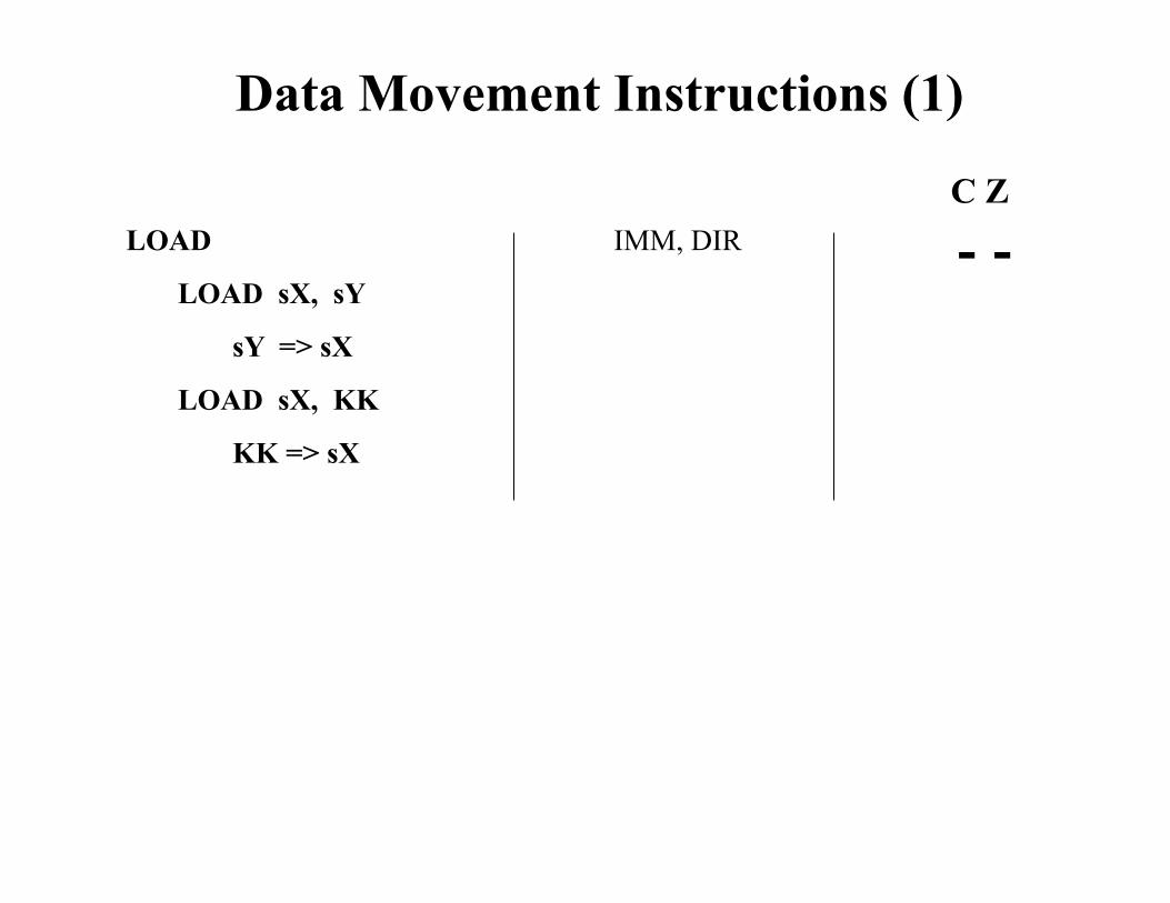
Data Movement Instructions (1)
LOAD
LOAD sX, sY
sY => sX
LOAD sX, KK
KK => sX
IMM, DIR C Z
- -
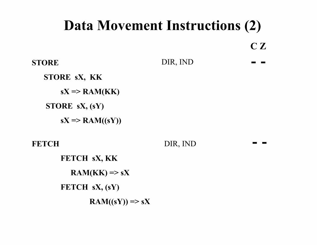
FETCH
FETCH sX, KK
RAM(KK) => sX
FETCH sX, (sY)
RAM((sY)) => sX
Data Movement Instructions (2)
DIR, IND
C Z
- - STORE
STORE sX, KK
sX => RAM(KK)
STORE sX, (sY)
sX => RAM((sY))
DIR, IND
- -
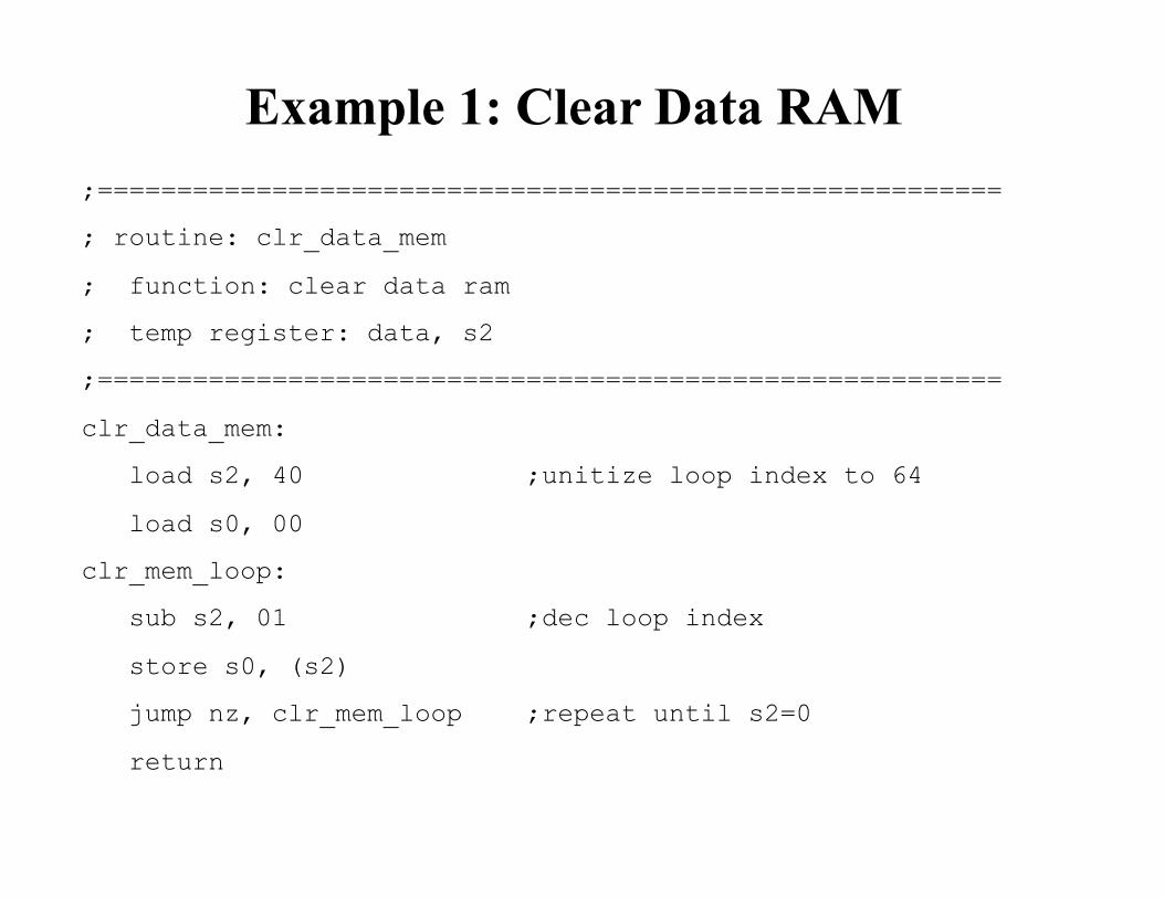
Example 1: Clear Data RAM ;=========================================================
; routine: clr_data_mem
; function: clear data ram
; temp register: data, s2
;=========================================================
clr_data_mem:
load s2, 40 ;unitize loop index to 64
load s0, 00
clr_mem_loop:
sub s2, 01 ;dec loop index
store s0, (s2)
jump nz, clr_mem_loop ;repeat until s2=0
return
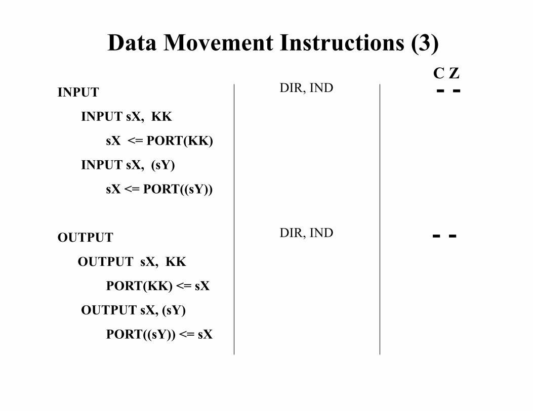
Data Movement Instructions (3)
INPUT
INPUT sX, KK
sX <= PORT(KK)
INPUT sX, (sY)
sX <= PORT((sY))
OUTPUT
OUTPUT sX, KK
PORT(KK) <= sX
OUTPUT sX, (sY)
PORT((sY)) <= sX
DIR, IND
DIR, IND
C Z - -
- -
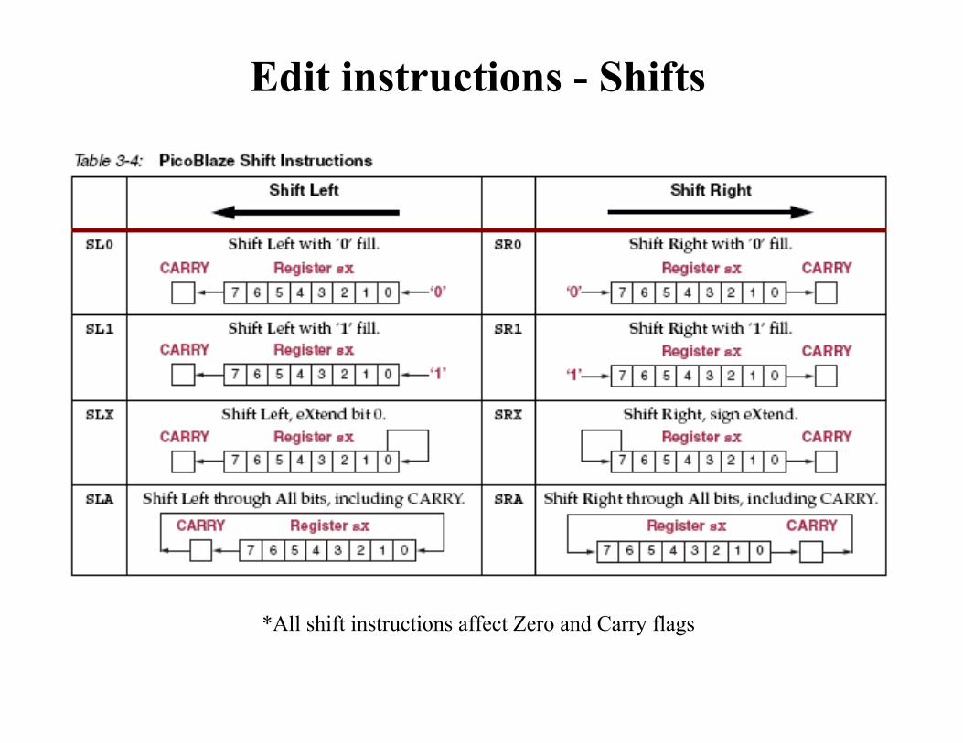
Edit instructions - Shifts
*All shift instructions affect Zero and Carry flags
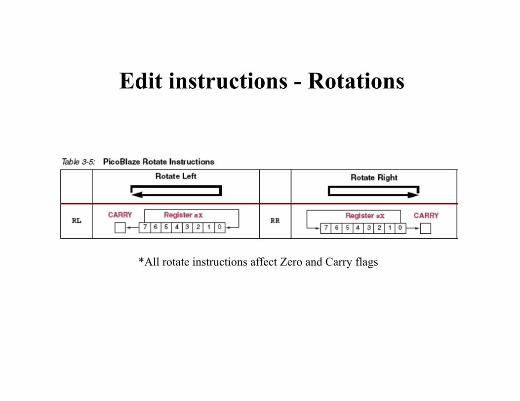
Edit instructions - Rotations
*All rotate instructions affect Zero and Carry flags
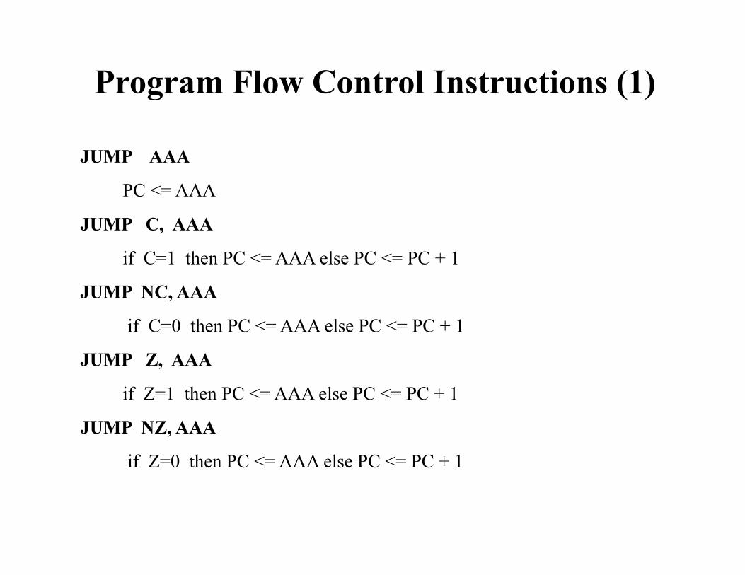
Program Flow Control Instructions (1)
JUMP AAA
PC <= AAA
JUMP C, AAA
if C=1 then PC <= AAA else PC <= PC + 1
JUMP NC, AAA
if C=0 then PC <= AAA else PC <= PC + 1
JUMP Z, AAA
if Z=1 then PC <= AAA else PC <= PC + 1
JUMP NZ, AAA
if Z=0 then PC <= AAA else PC <= PC + 1
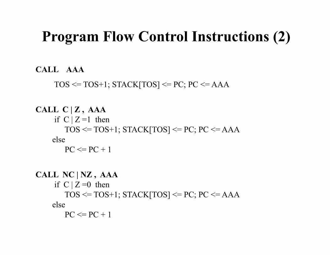
Program Flow Control Instructions (2)
CALL AAA
TOS <= TOS+1; STACK[TOS] <= PC; PC <= AAA
CALL C | Z , AAA if C | Z =1 then TOS <= TOS+1; STACK[TOS] <= PC; PC <= AAA else PC <= PC + 1
CALL NC | NZ , AAA if C | Z =0 then TOS <= TOS+1; STACK[TOS] <= PC; PC <= AAA else PC <= PC + 1
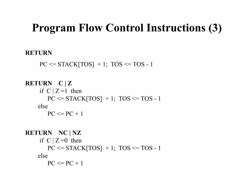
Program Flow Control Instructions (3)
RETURN
PC <= STACK[TOS] + 1; TOS <= TOS - 1
RETURN C | Z if C | Z =1 then PC <= STACK[TOS] + 1; TOS <= TOS - 1 else PC <= PC + 1
RETURN NC | NZ if C | Z =0 then PC <= STACK[TOS] + 1; TOS <= TOS - 1 else PC <= PC + 1
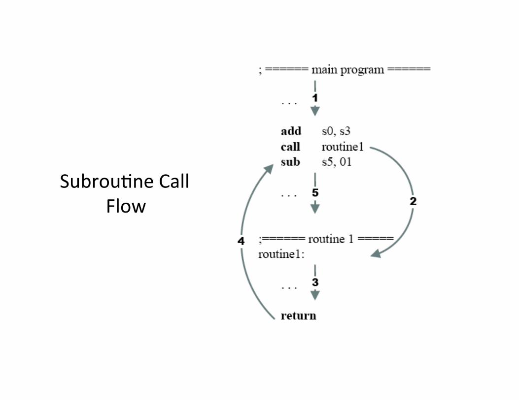
Subrou&ne Call Flow
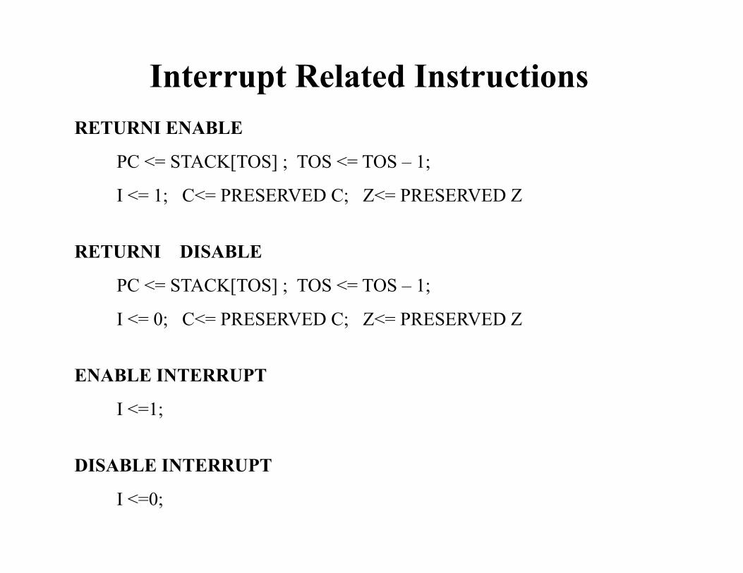
Interrupt Related Instructions RETURNI ENABLE
PC <= STACK[TOS] ; TOS <= TOS – 1;
I <= 1; C<= PRESERVED C; Z<= PRESERVED Z
RETURNI DISABLE
PC <= STACK[TOS] ; TOS <= TOS – 1;
I <= 0; C<= PRESERVED C; Z<= PRESERVED Z
ENABLE INTERRUPT
I <=1;
DISABLE INTERRUPT
I <=0;
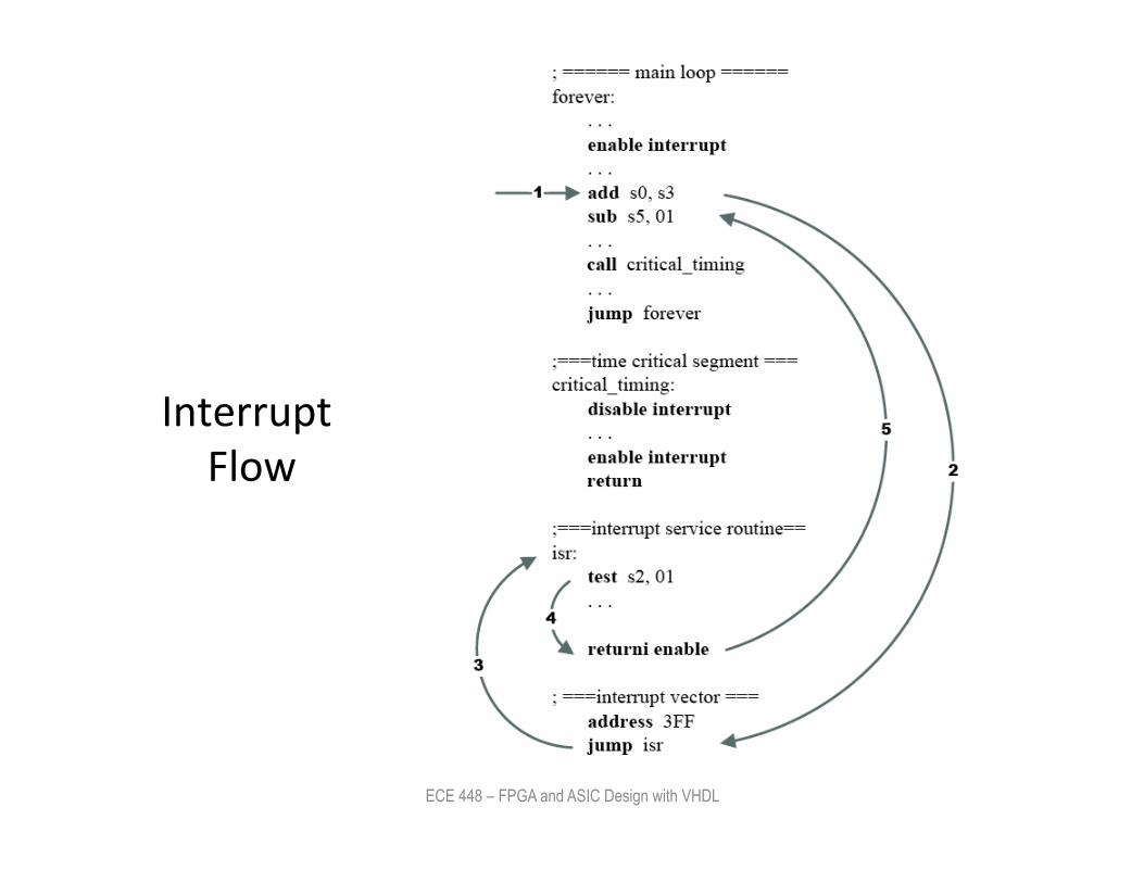
Interrupt Flow
ECE 448 – FPGA and ASIC Design with VHDL
26
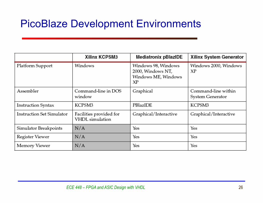
PicoBlaze Development Environments
ECE 448 – FPGA and ASIC Design with VHDL
27
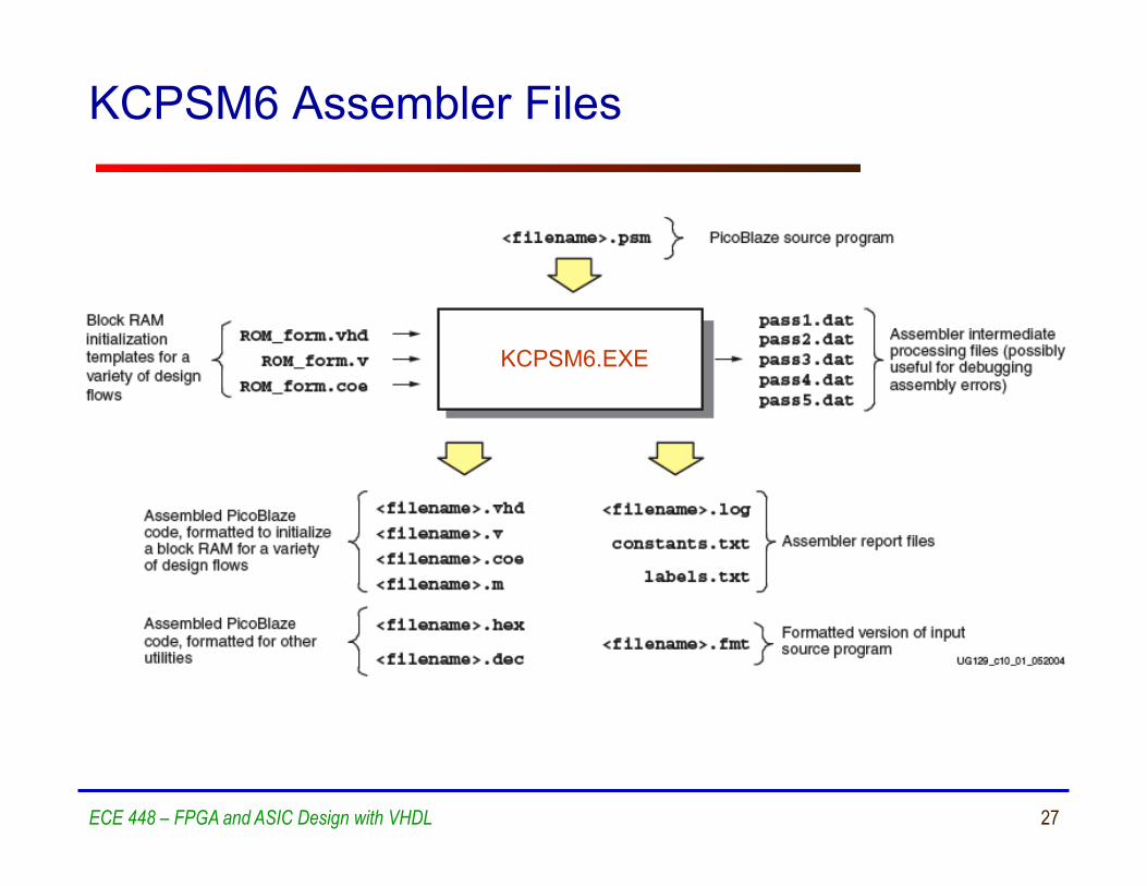
KCPSM6 Assembler Files
ECE 448 – FPGA and ASIC Design with VHDL
KCPSM6.EXE
28
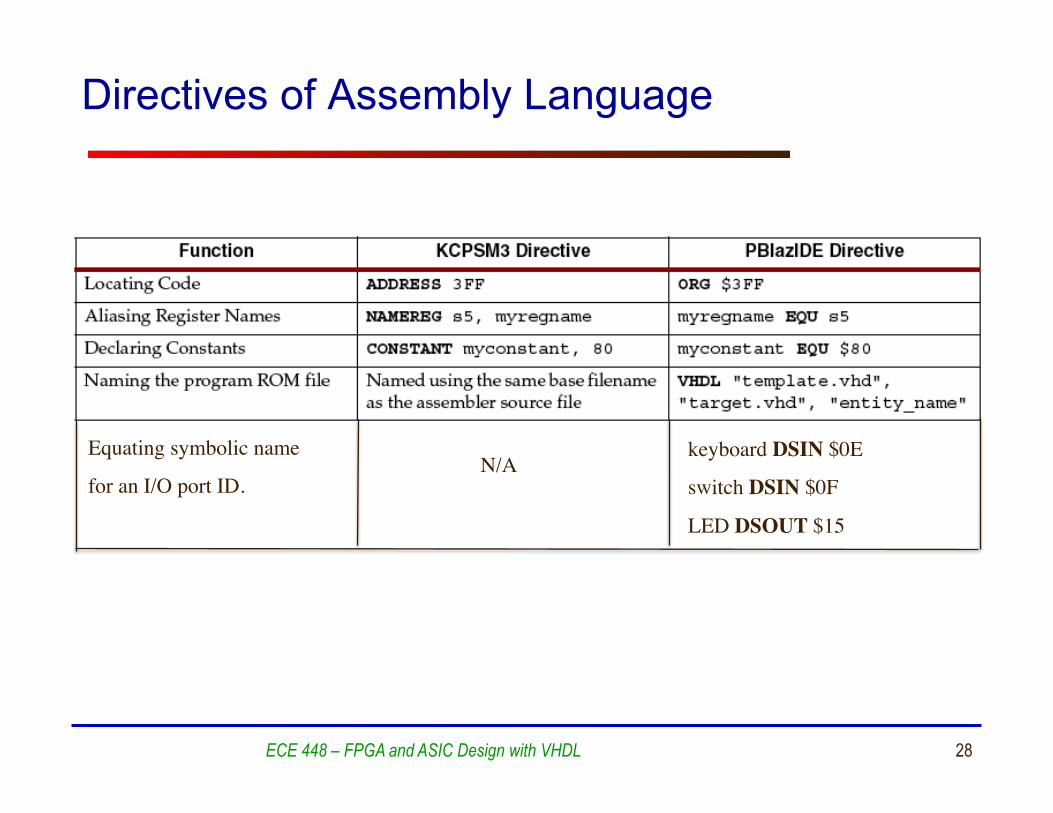
Directives of Assembly Language
ECE 448 – FPGA and ASIC Design with VHDL
Equating symbolic name
for an I/O port ID.
keyboard DSIN $0E
switch DSIN $0F
LED DSOUT $15
N/A
29
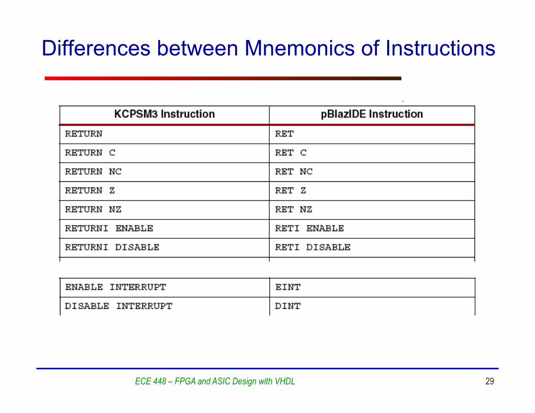
Differences between Mnemonics of Instructions
ECE 448 – FPGA and ASIC Design with VHDL
30
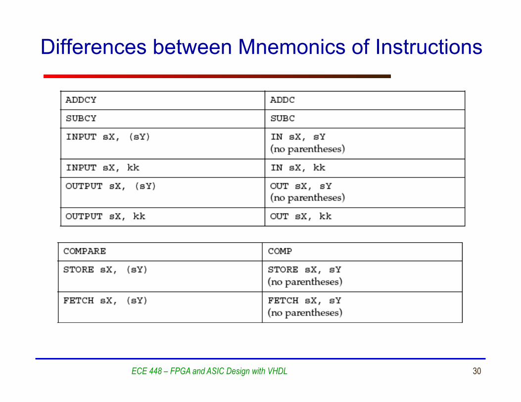
Differences between Mnemonics of Instructions
ECE 448 – FPGA and ASIC Design with VHDL
31
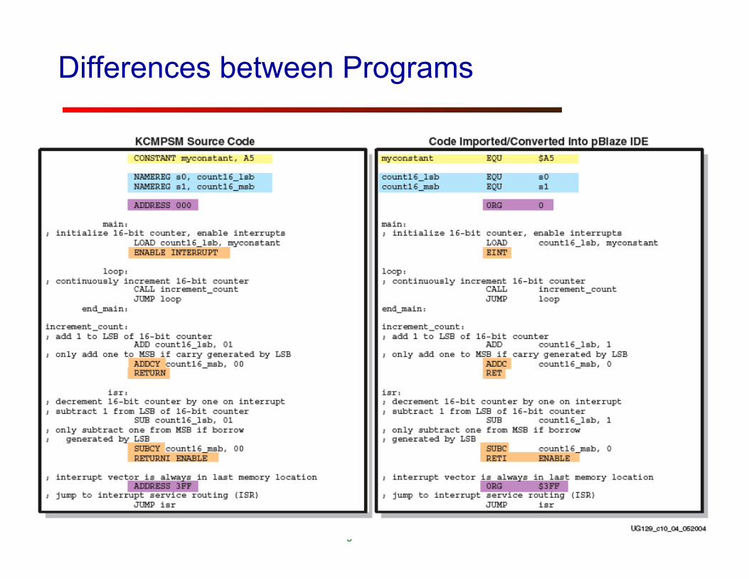
Differences between Programs
ECE 448 – FPGA and ASIC Design with VHDL