Embed Size (px)
Citation preview
ECEN 5645 Introduc0on to Optoelectronics
Class Mee0ng 9
Fabry-‐Perot Interferometers
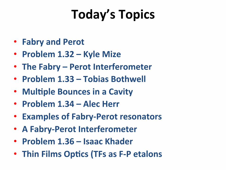
Today’s Topics
• Fabry and Perot • Problem 1.32 – Kyle Mize • The Fabry – Perot Interferometer • Problem 1.33 – Tobias Bothwell • Mul0ple Bounces in a Cavity • Problem 1.34 – Alec Herr • Examples of Fabry-‐Perot resonators • A Fabry-‐Perot Interferometer • Problem 1.36 – Isaac Khader • Thin Films Op0cs (TFs as F-‐P etalons
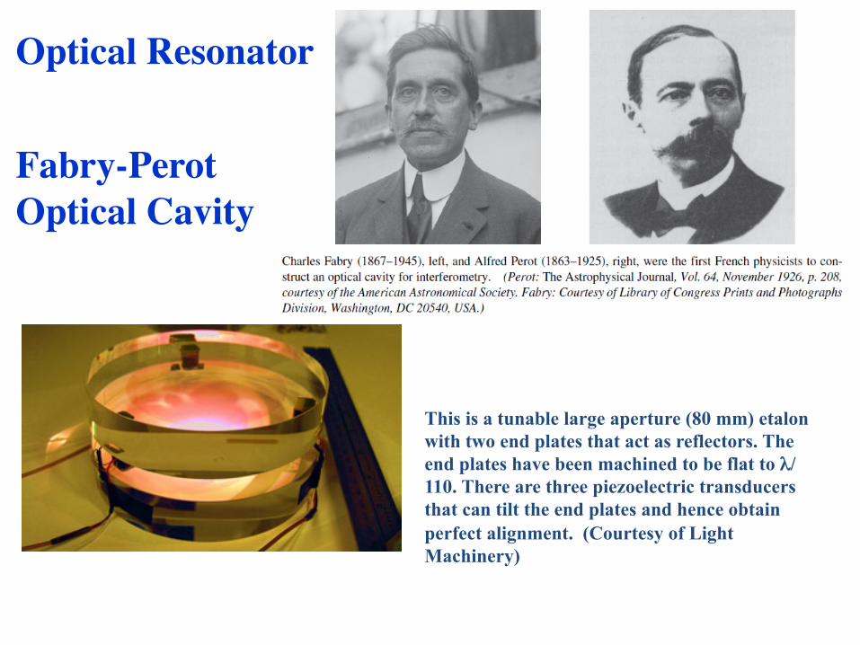
Optical Resonator���
Fabry-Perot���Optical Cavity
This is a tunable large aperture (80 mm) etalon with two end plates that act as reflectors. The end plates have been machined to be flat to λ/110. There are three piezoelectric transducers that can tilt the end plates and hence obtain perfect alignment. (Courtesy of Light Machinery)
Problem Set 4 Problem 1.32
• This is not the same problem as in the “interna0onal” edi0on. What gives?
• Next is problem from the interna0onal edi0on
Optoelectronics
Homework problem 1.32 presenta0on
By Kyle Mize
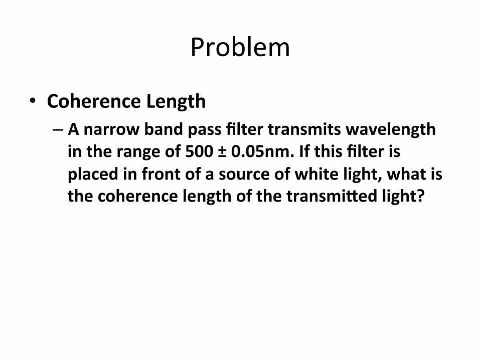
Problem
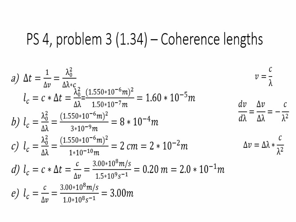
• Coherence Length – A narrow band pass filter transmits wavelength in the range of 500 ± 0.05nm. If this filter is placed in front of a source of white light, what is the coherence length of the transmi^ed light?
Ques2on Parameters
• Given: – Frequency Width – Center Frequency
• Solve for:
• Equa0ons Used –
Solu2on (spectral width)
• Solve for spectral width
Solu2on (coherence 2me)
• Solve for coherence 0me – Δ𝑡≈1/∆𝑣
– ∆𝑡= 1/(0.12∗10↑12 ) [𝑠]
– ∆𝑡=8.33 ∗10↑−12 [𝑠]
– ∆𝑡=8.33 [𝑝𝑠]
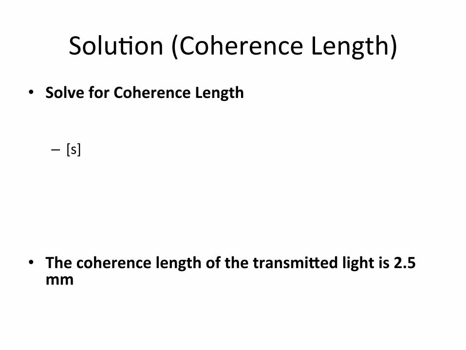
Solu2on (Coherence Length) • Solve for Coherence Length
– [s]
• The coherence length of the transmi^ed light is 2.5 mm
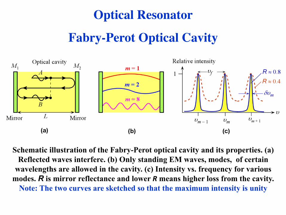
Optical Resonator
Fabry-Perot Optical Cavity
Schematic illustration of the Fabry-Perot optical cavity and its properties. (a) Reflected waves interfere. (b) Only standing EM waves, modes, of certain
wavelengths are allowed in the cavity. (c) Intensity vs. frequency for various modes. R is mirror reflectance and lower R means higher loss from the cavity.
Note: The two curves are sketched so that the maximum intensity is unity
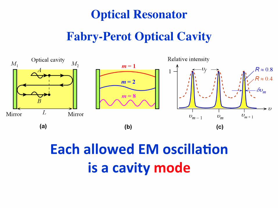
Each allowed EM oscilla0on is a cavity mode
Optical Resonator
Fabry-Perot Optical Cavity
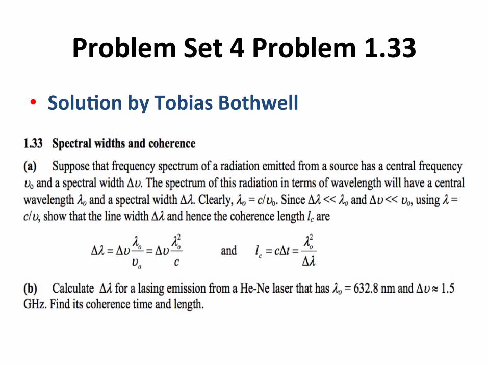
Problem Set 4 Problem 1.33
• Solu0on by Tobias Bothwell
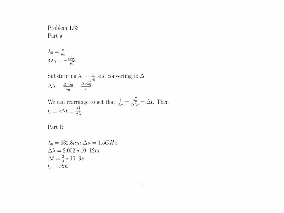
Problem 1.33
Part a
�0 =c⌫0
��0 = �c�⌫0⌫20
Substituting �0 =c⌫0
and converting to �
�� =
�⌫�0⌫0
=
�⌫�20c .
We can rearrange to get that
1�⌫ =
�20��c = �t. Then
lc = c�t = �20��.
Part B
�0 = 632.8nm �⌫ = 1.5GHz
�� = 2.002 ⇤ 10�12m�t = 2
3 ⇤ 10�9s
lc = .2m
1
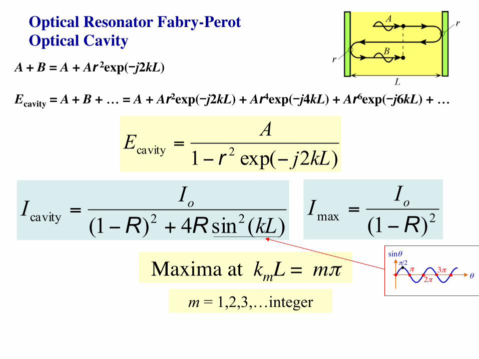
Optical Resonator Fabry-Perot���Optical Cavity
A + B = A + Ar 2exp(-j2kL)
Ecavity = A + B + … = A + Ar2exp(-j2kL) + Ar4exp(-j4kL) + Ar6exp(-j6kL) + …
Maxima at kmL = mπ
)2exp(1 2cavity kLjAE−−
=r
)(sin4)1( 22cavity kLII o
RR +−= 2max )1( R−
= oII
m = 1,2,3,…integer
θ
sinθ
π2π
3ππ/2
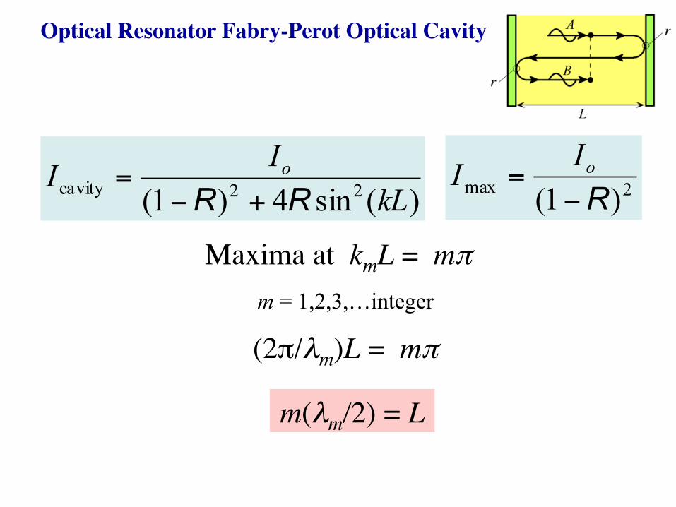
Optical Resonator Fabry-Perot Optical Cavity
Maxima at kmL = mπ
)(sin4)1( 22cavity kLII o
RR +−= 2max )1( R−
= oII
m = 1,2,3,…integer
m(λm/2) = L
(2π/λm)L = mπ
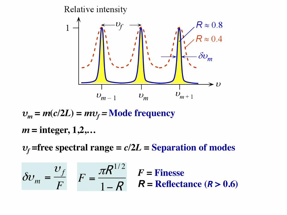
υm = m(c/2L) = mυf = Mode frequency
m = integer, 1,2,…
υf =free spectral range = c/2L = Separation of modes
€
δυm =υ f
F
€
F =πR 1/ 2
1−RF = Finesse���R = Reflectance (R > 0.6)
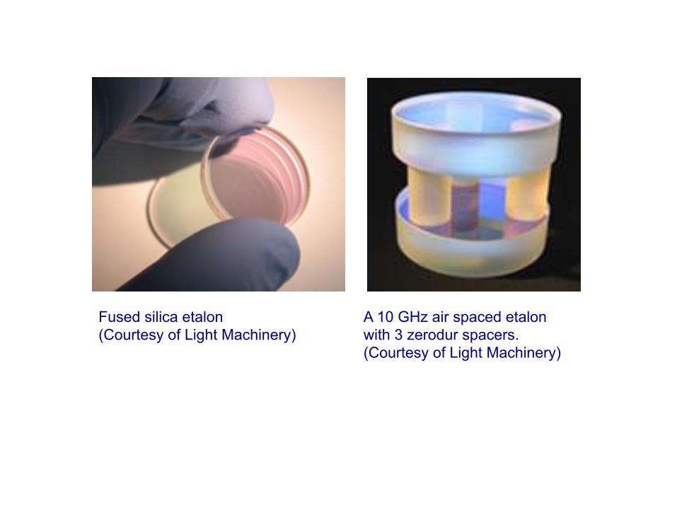
Fused silica etalon (Courtesy of Light Machinery)
A 10 GHz air spaced etalon with 3 zerodur spacers. (Courtesy of Light Machinery)
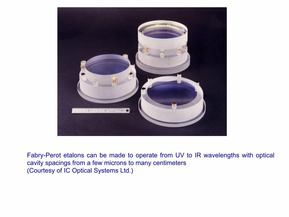
Fabry-Perot etalons can be made to operate from UV to IR wavelengths with optical cavity spacings from a few microns to many centimeters (Courtesy of IC Optical Systems Ltd.)
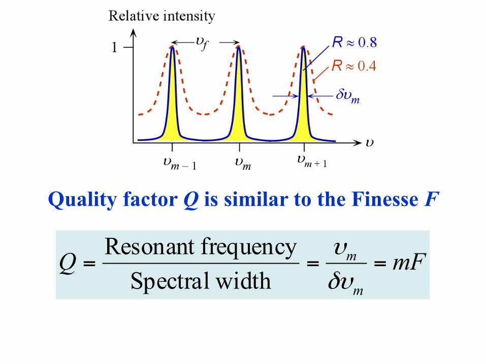
Quality factor Q is similar to the Finesse F
mFQm
m ===δυυ
widthSpectralfrequencyResonant
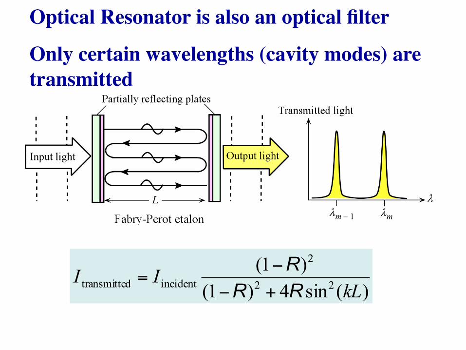
Optical Resonator is also an optical filter
Only certain wavelengths (cavity modes) are transmitted
)(sin4)1()1(
22
2
incidentdtransmitte kLII
RRR
+−−
=
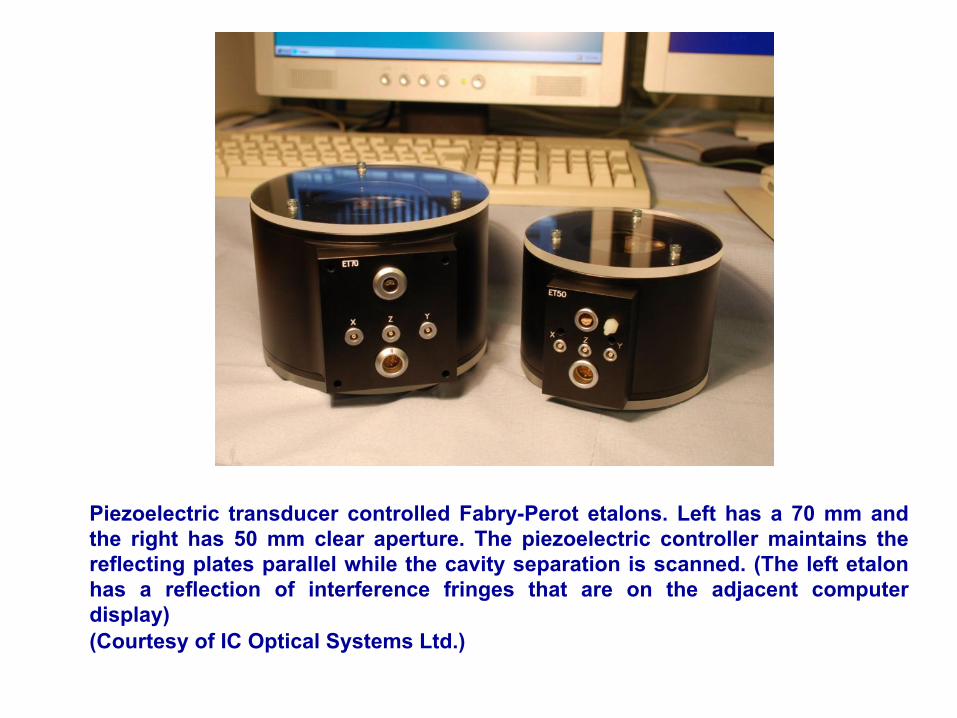
Piezoelectric transducer controlled Fabry-Perot etalons. Left has a 70 mm and the right has 50 mm clear aperture. The piezoelectric controller maintains the reflecting plates parallel while the cavity separation is scanned. (The left etalon has a reflection of interference fringes that are on the adjacent computer display) (Courtesy of IC Optical Systems Ltd.)
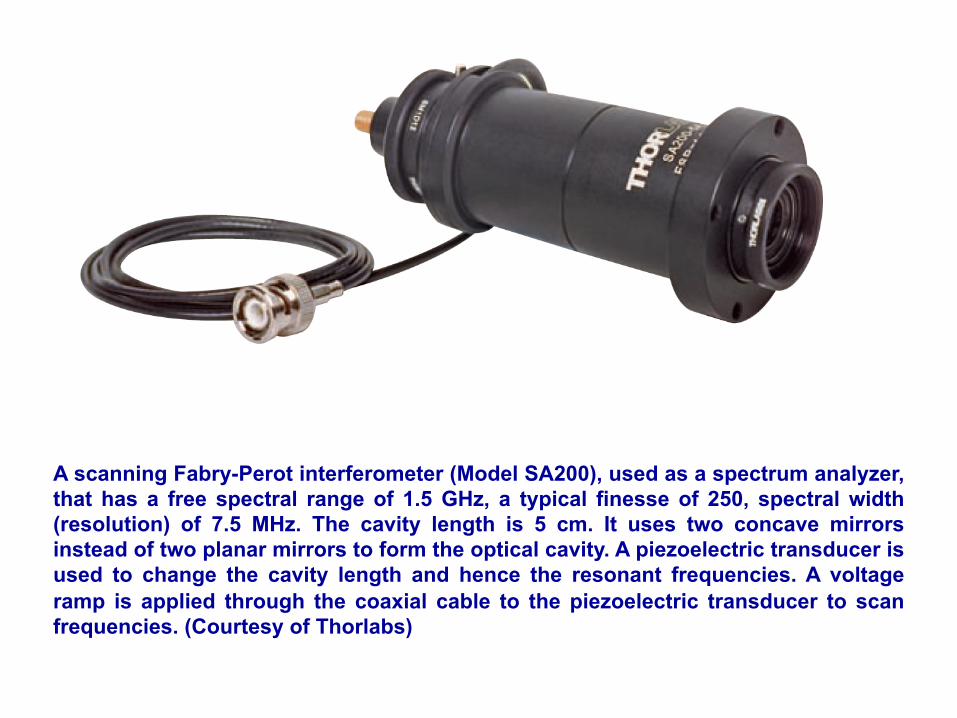
A scanning Fabry-Perot interferometer (Model SA200), used as a spectrum analyzer, that has a free spectral range of 1.5 GHz, a typical finesse of 250, spectral width (resolution) of 7.5 MHz. The cavity length is 5 cm. It uses two concave mirrors instead of two planar mirrors to form the optical cavity. A piezoelectric transducer is used to change the cavity length and hence the resonant frequencies. A voltage ramp is applied through the coaxial cable to the piezoelectric transducer to scan frequencies. (Courtesy of Thorlabs)
Problem Set 4 Problem 1.34
• Solu0on by Alec Herr
Fabry Perot Examples
• Op0cal Resonator in air • Op0cal Resonator in semiconductor
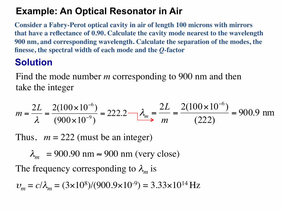
Example: An Optical Resonator in Air Consider a Fabry-Perot optical cavity in air of length 100 microns with mirrors that have a reflectance of 0.90. Calculate the cavity mode nearest to the wavelength 900 nm, and corresponding wavelength. Calculate the separation of the modes, the finesse, the spectral width of each mode and the Q-factor
Thus, m = 222 (must be an integer)
λm = 900.90 nm ≈ 900 nm (very close)
Solution
2.222)10900()10100(22
9
6
=××
== −
−
λLm nm9.900
)222()10100(22 6
=×
==−
mL
mλ
The frequency corresponding to λm is
υm = c/λm = (3×10⁸)/(900.9×10-9) = 3.33×10¹⁴ Hz
Find the mode number m corresponding to 900 nm and then take the integer
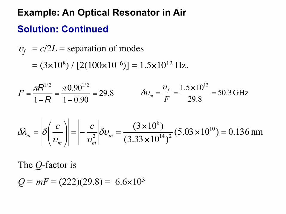
Example: An Optical Resonator in Air
υf = c/2L = separation of modes
= (3×10⁸) / [2(100×10-6)] = 1.5×10¹² Hz.
8.2990.0190.0
1
2/12/1
=−
=−
=ππ
RRF GHz 3.50
8.29105.1 12
=×
==Ff
m
υδυ
nm 136.0)1003.5()1033.3(
)103( 10214
8
2 =×××
=−=⎟⎟⎠
⎞⎜⎜⎝
⎛= m
mmm
ccδυ
υυδδλ
Solution: Continued
The Q-factor is
Q = mF = (222)(29.8) = 6.6×10³
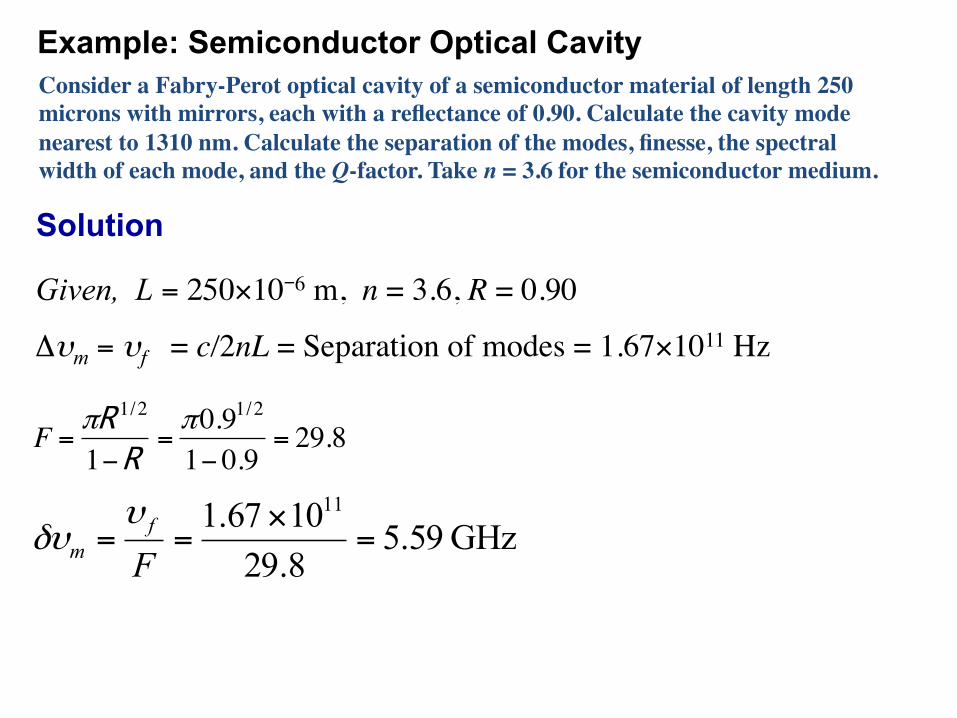
Example: Semiconductor Optical Cavity Consider a Fabry-Perot optical cavity of a semiconductor material of length 250 microns with mirrors, each with a reflectance of 0.90. Calculate the cavity mode nearest to 1310 nm. Calculate the separation of the modes, finesse, the spectral width of each mode, and the Q-factor. Take n = 3.6 for the semiconductor medium.
Given, L = 250×10-6 m, n = 3.6, R = 0.90
Δυm = υf = c/2nL = Separation of modes = 1.67×10¹¹ Hz
€
F =πR 1/2
1−R =π0.91/2
1− 0.9= 29.8
GHz 59.58.291067.1 11
=×
==Ff
m
υδυ
Solution
05.1374)101310()10250)(6.3(22
9
6
=××
== −
−
λnLm
Mode number m corresponding to 1310 nm is
which must be an integer (1374) so that the actual mode wavelength is
nm04.1310)1374(
)10250)(6.3(22 6
=×
==−
mnL
mλ
For all prac2cal purposes the mode wavelength is 1310 nm
Mode frequency is
Hz103.2)101310(
)103( 149
8
×=××
== −m
mcλ
υ
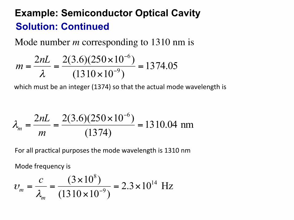
Solution: Continued Example: Semiconductor Optical Cavity
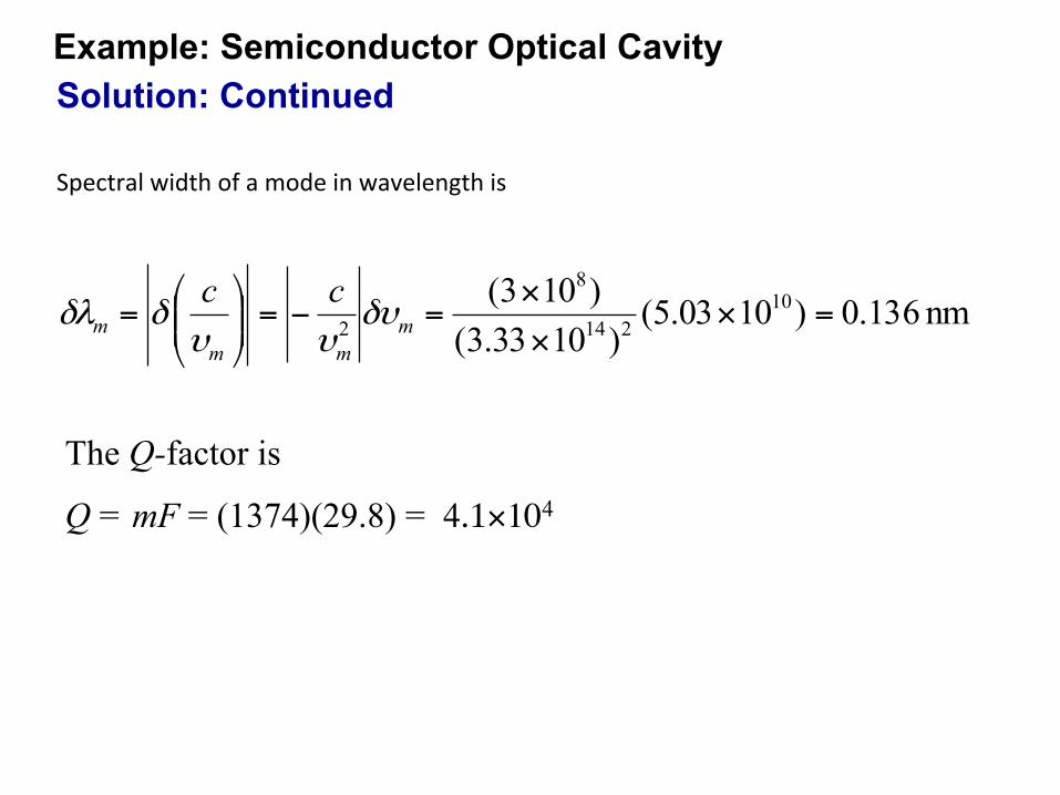
nm 136.0)1003.5()1033.3(
)103( 10214
8
2 =×××
=−=⎟⎟⎠
⎞⎜⎜⎝
⎛= m
mmm
ccδυ
υυδδλ
Spectral width of a mode in wavelength is
The Q-factor is
Q = mF = (1374)(29.8) = 4.1×10⁴
Solution: Continued Example: Semiconductor Optical Cavity
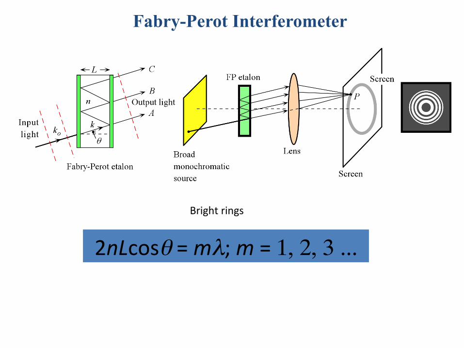
Fabry-Perot Interferometer
Bright rings
2nLcosθ = mλ; m = 1, 2, 3 ...
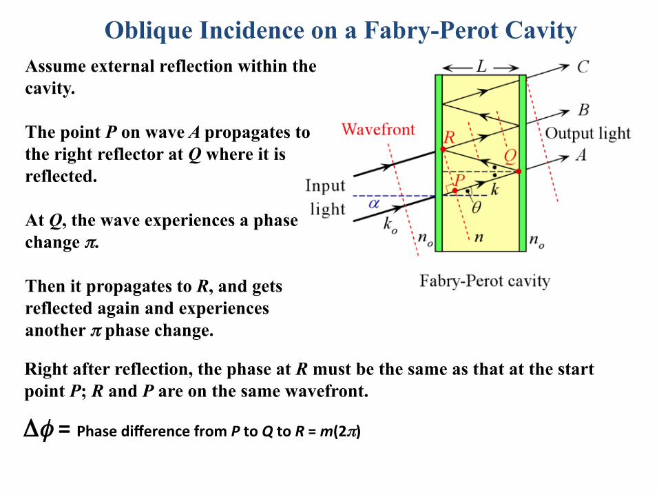
Oblique Incidence on a Fabry-Perot Cavity Assume external reflection within the cavity. The point P on wave A propagates to the right reflector at Q where it is reflected. At Q, the wave experiences a phase change π. Then it propagates to R, and gets reflected again and experiences another π phase change.
Right after reflection, the phase at R must be the same as that at the start point P; R and P are on the same wavefront.
Δφ = Phase difference from P to Q to R = m(2π)
Some Shop Tes0ng Examples
• Classic text for applica0ons and pictures of results, aberra0ons, etc. Now online…
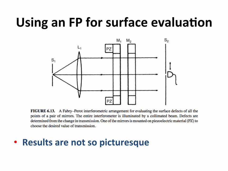
Using an FP for surface evalua0on
• Results are not so picturesque
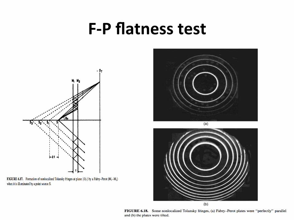
F-‐P flatness test
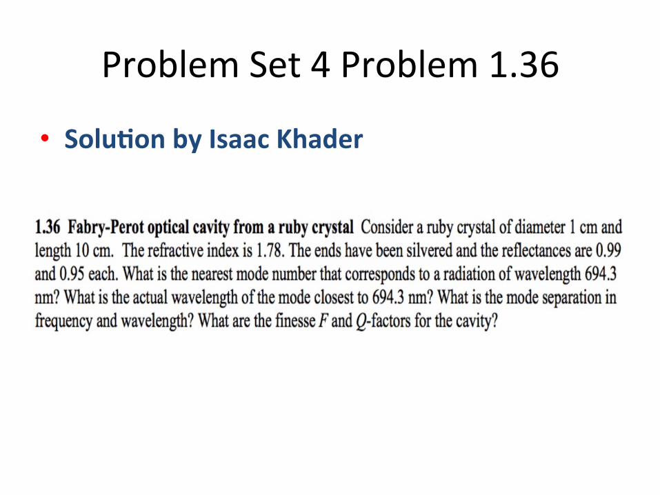
Problem Set 4 Problem 1.36
• Solu0on by Isaac Khader
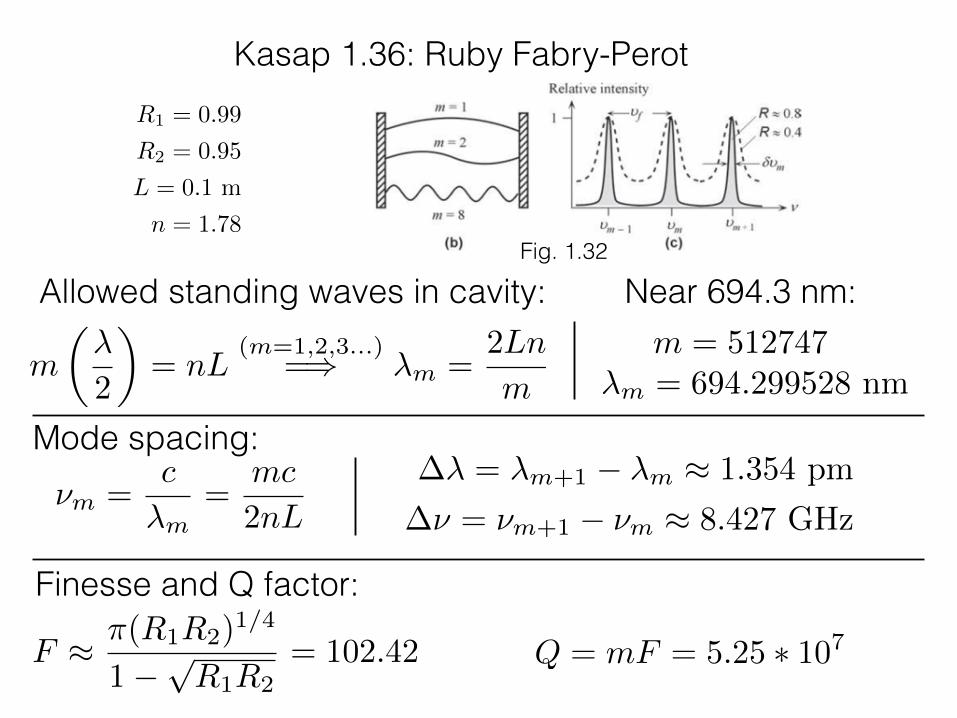
Kasap 1.36: Ruby Fabry-PerotR1 = 0.99
R2 = 0.95
L = 0.1 m
n = 1.78Fig. 1.32
Allowed standing waves in cavity: Near 694.3 nm:m = 512747
⌫m =c
�m=
mc
2nL
m
✓�
2
◆= nL
(m=1,2,3...)=) �m =
2Ln
m
�� = �m+1 � �m ⇡ 1.354 pm
�⌫ = ⌫m+1 � ⌫m ⇡ 8.427 GHz
�m = 694.299528 nm
Mode spacing:
Finesse and Q factor:
Q = mF = 5.25 ⇤ 107F ⇡ ⇡(R1R2)1/4
1�pR1R2
= 102.42
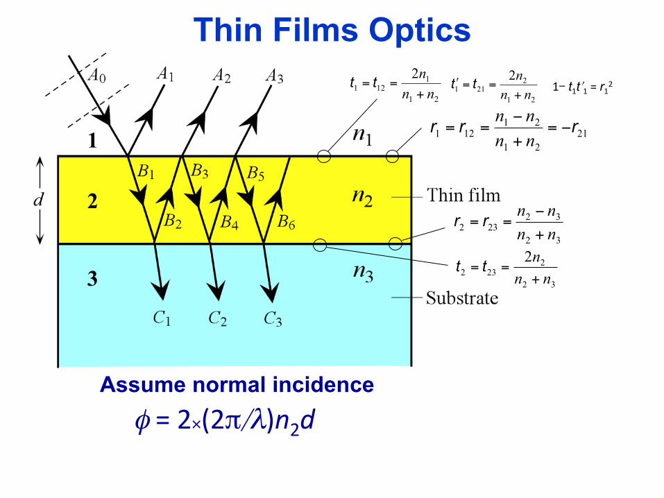
Thin Films Optics
Assume normal incidence φ = 2×(2π/λ)n2d
2121
21121 rrr −=
+−
==nnnn
32
32232 nn
nn+−
== rr
21
1121
2nnn+
== tt21
2211
2nnn+
==ʹ′ tt
32
2232
2nnn+
== tt
2
3
1
1- t1tʹ′1 = r12
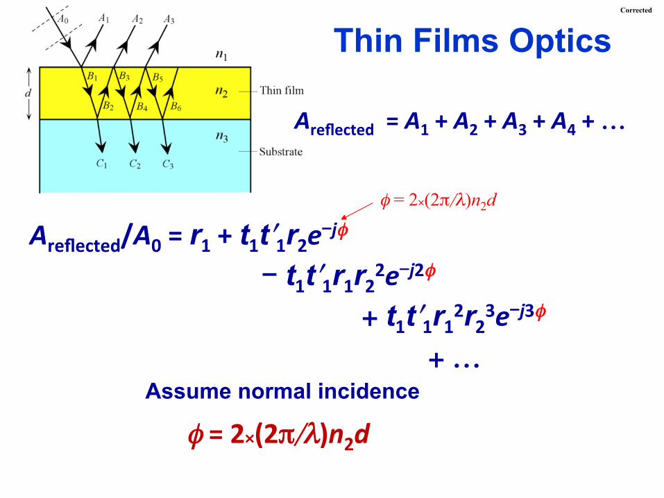
Thin Films Optics
φ = 2×(2π/λ)n2d Assume normal incidence
Areflected/A0 = r1 + t1tʹ′1r2e-jφ - t1tʹ′1r1r22e-j2φ
+ t1tʹ′1r12r23e-j3φ + …
Areflected = A1 + A2 + A3 + A4 + …
φ = 2×(2π/λ)n2d
Corrected
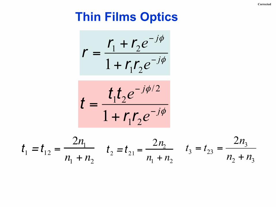
Thin Films Optics
t1 = t12 =2n1
n1 + n2t 2 = t 21 =
2n2n1 + n2
33 23
2 3
2nt tn n
= =+
φ
φ
j
j
ee−
−
++
=21
21
1 rrrrr
φ
φ
j
j
ee
−
−
+=
21
2/21
1 rrttt
Corrected
φ
φ
j
j
ee−
−
++
=21
21
1 rrrrr
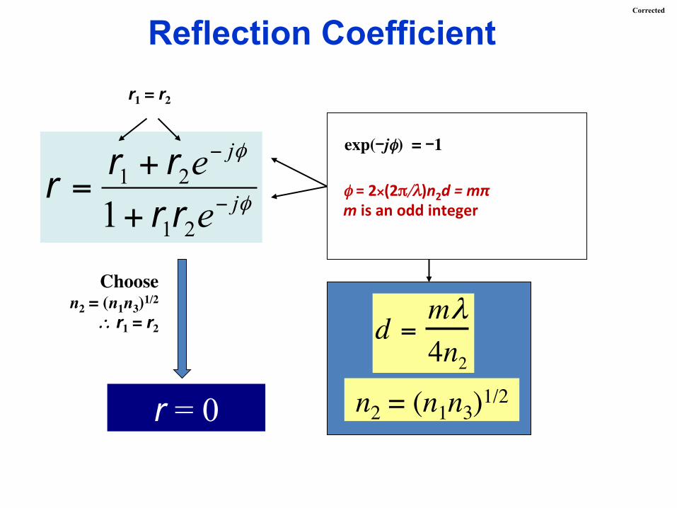
Reflection Coefficient
r = 0
d = mλ4n2
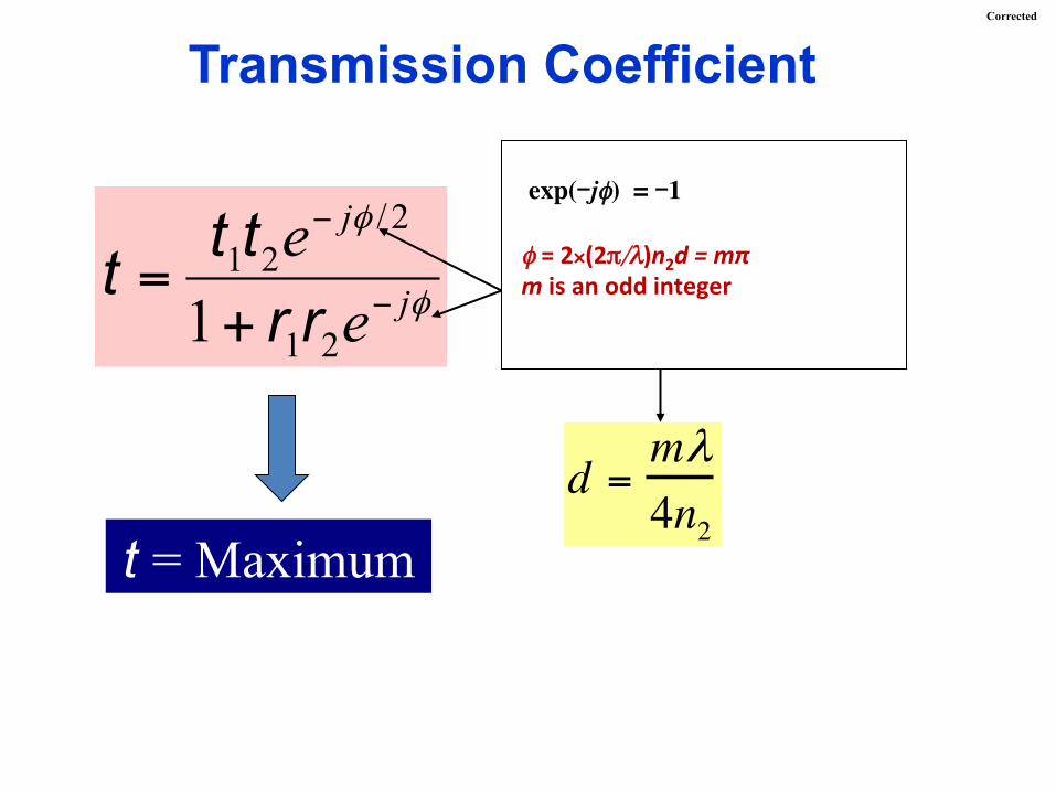
exp(-jφ) = -1
r1 = r2
Choosen2 = (n1n3)1/2
∴ r1 = r2
n2 = (n1n3)1/2
φ = 2×(2π/λ)n2d = mπ m is an odd integer
Corrected
φ
φ
j
j
ee
−
−
+=
21
2/21
1 rrttt
Transmission Coefficient
t = Maximum d = mλ
4n2
exp(-jφ) = -1
φ = 2×(2π/λ)n2d = mπ m is an odd integer
Corrected
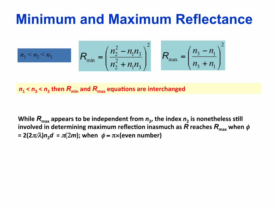
Minimum and Maximum Reflectance 2
3122
3122
min ⎟⎟⎠
⎞⎜⎜⎝
⎛
+−
=nnnnnnR
2
13
13max ⎟⎟
⎠
⎞⎜⎜⎝
⎛
+−
=nnnnRn1 < n2 < n3
n1 < n3 < n2 then Rmin and Rmax equa0ons are interchanged
While Rmax appears to be independent from n2, the index n2 is nonetheless s0ll involved in determining maximum reflec0on inasmuch as R reaches Rmax when φ = 2(2π/λ)n2d = π(2m); when φ = π×(even number)
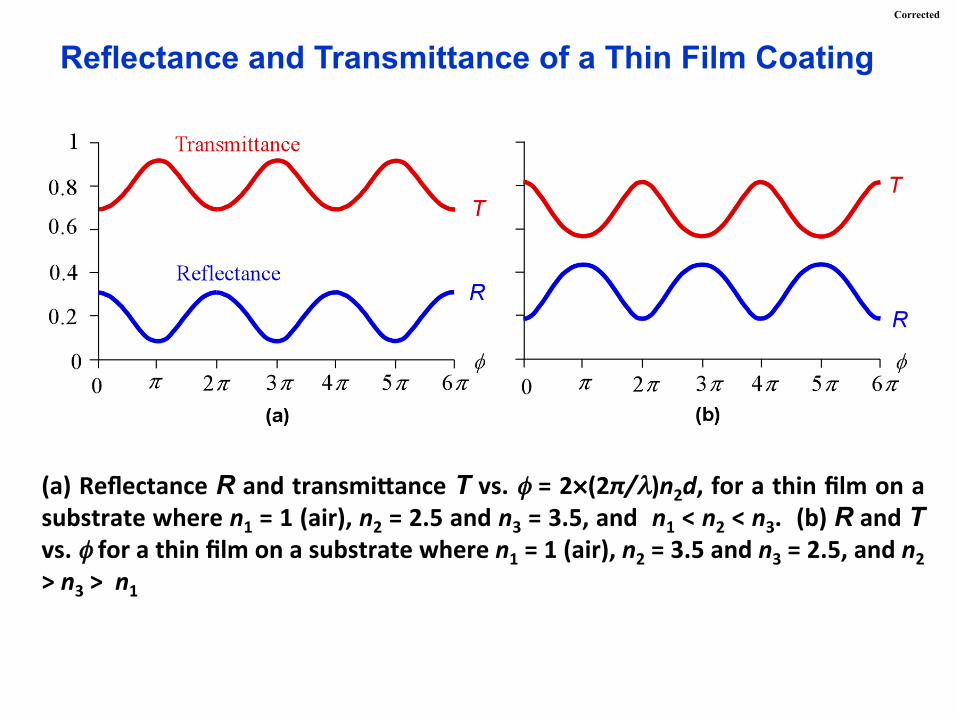
Reflectance and Transmittance of a Thin Film Coating
(a) Reflectance R and transmi^ance T vs. φ = 2×(2π/λ)n2d, for a thin film on a substrate where n1 = 1 (air), n2 = 2.5 and n3 = 3.5, and n1 < n2 < n3. (b) R and T vs. φ for a thin film on a substrate where n1 = 1 (air), n2 = 3.5 and n3 = 2.5, and n2 > n3 > n1
Corrected
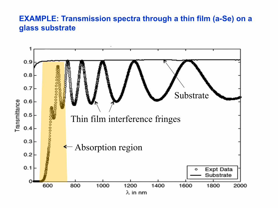
EXAMPLE: Transmission spectra through a thin film (a-Se) on a glass substrate
Absorption region
Thin film interference fringes
Substrate
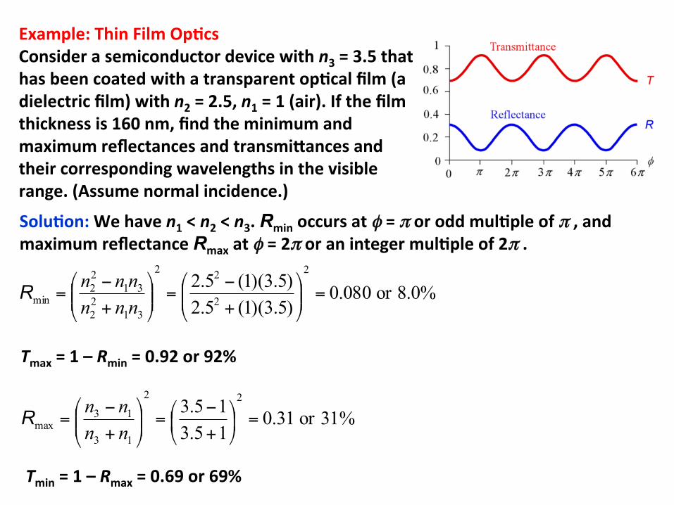
Example: Thin Film Op0cs Consider a semiconductor device with n3 = 3.5 that has been coated with a transparent op0cal film (a dielectric film) with n2 = 2.5, n1 = 1 (air). If the film thickness is 160 nm, find the minimum and maximum reflectances and transmi^ances and their corresponding wavelengths in the visible range. (Assume normal incidence.)
Solu0on: We have n1 < n2 < n3. Rmin occurs at φ = π or odd mul0ple of π , and maximum reflectance Rmax at φ = 2π or an integer mul0ple of 2π .
%0.8or080.0)5.3)(1(5.2)5.3)(1(5.22
2
22
3122
3122
min =⎟⎟⎠
⎞⎜⎜⎝
⎛
+−
=⎟⎟⎠
⎞⎜⎜⎝
⎛
+−
=nnnnnnR
%31or31.015.315.3 22
13
13max =⎟
⎠
⎞⎜⎝
⎛+−
=⎟⎟⎠
⎞⎜⎜⎝
⎛
+−
=nnnnR
Tmax = 1 – Rmin = 0.92 or 92%
Tmin = 1 – Rmax = 0.69 or 69%
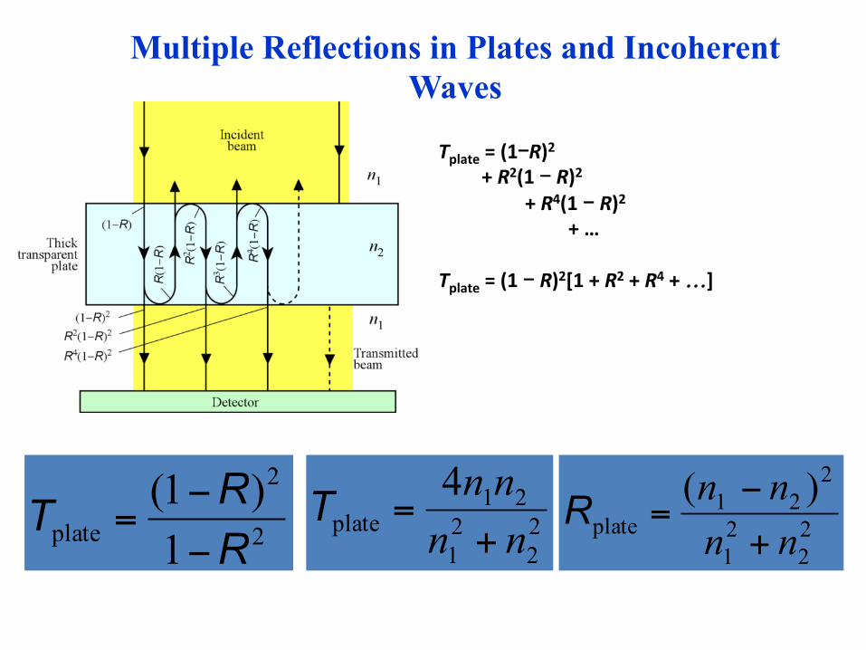
Multiple Reflections in Plates and Incoherent Waves
Tplate = (1-R)2 + R2(1 - R)2 + R4(1 - R)2 + …
Tplate = (1 - R)2[1 + R2 + R4 + …]
2
2
plate 1)1(
RRT
−−
= 22
21
21plate
4nnnn+
=T22
21
221
plate)(nnnn+−
=R