Embed Size (px)
Citation preview
Sam PalermoAnalog & Mixed-Signal Center
Texas A&M University
ECEN720: High-Speed Links Circuits and Systems
Spring 2019
Lecture 10: Jitter

Announcements
• Lab 5 Report and Prelab 6 due Mar. 27
• Reference Material• Jitter application notes posted on website• Majority of today’s material from Hall reference
2
Agenda
• Jitter Definitions
• Jitter Categories
• Dual Dirac Jitter Model
• System Jitter Budgeting
3
Eye Diagram and Spec Mask
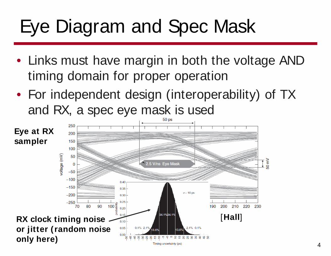
• Links must have margin in both the voltage AND timing domain for proper operation
• For independent design (interoperability) of TX and RX, a spec eye mask is used
4
Eye at RX sampler
RX clock timing noise or jitter (random noise only here)
[Hall]
Jitter Definitions
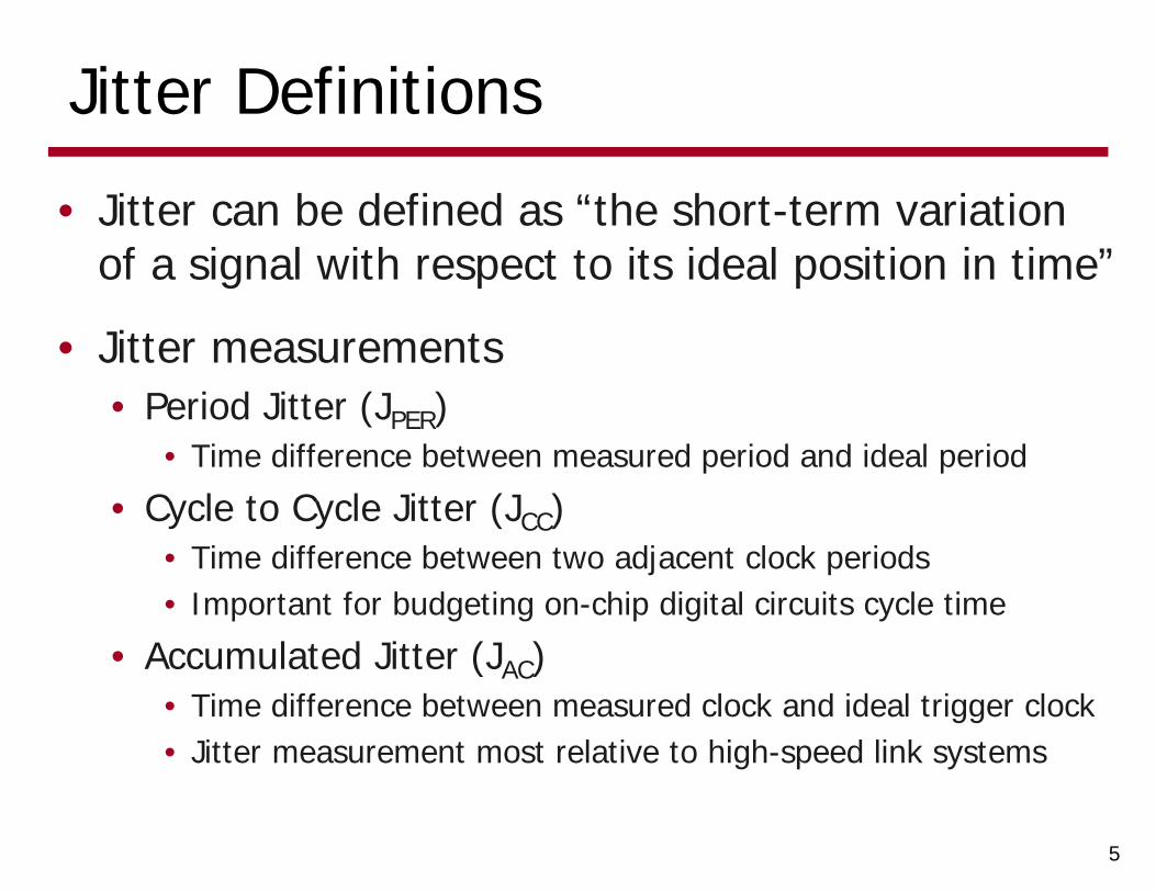
• Jitter can be defined as “the short-term variation of a signal with respect to its ideal position in time”
• Jitter measurements• Period Jitter (JPER)
• Time difference between measured period and ideal period
• Cycle to Cycle Jitter (JCC)• Time difference between two adjacent clock periods• Important for budgeting on-chip digital circuits cycle time
• Accumulated Jitter (JAC)• Time difference between measured clock and ideal trigger clock• Jitter measurement most relative to high-speed link systems
5

Jitter Statistical Parameters
• Mean Value• Can be interpreted as a fixed timing offset or “skew”• Generally not important, as usually can corrected for
• RMS Jitter• Useful for characterizing random component of jitter
• Peak-to-Peak Jitter• Function of both deterministic (bounded) and random
(unbounded) jitter components• Must be quoted at a given BER to account for random
(unbounded) jitter
6
Jitter Calculation Examples
7
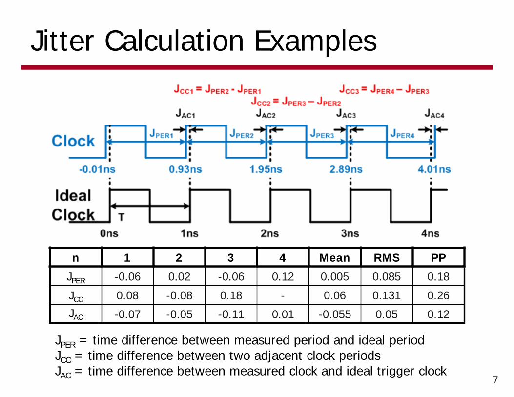
n 1 2 3 4 Mean RMS PP
JPER -0.06 0.02 -0.06 0.12 0.005 0.085 0.18
JCC 0.08 -0.08 0.18 - 0.06 0.131 0.26
JAC -0.07 -0.05 -0.11 0.01 -0.055 0.05 0.12
JPER = time difference between measured period and ideal periodJCC = time difference between two adjacent clock periodsJAC = time difference between measured clock and ideal trigger clock
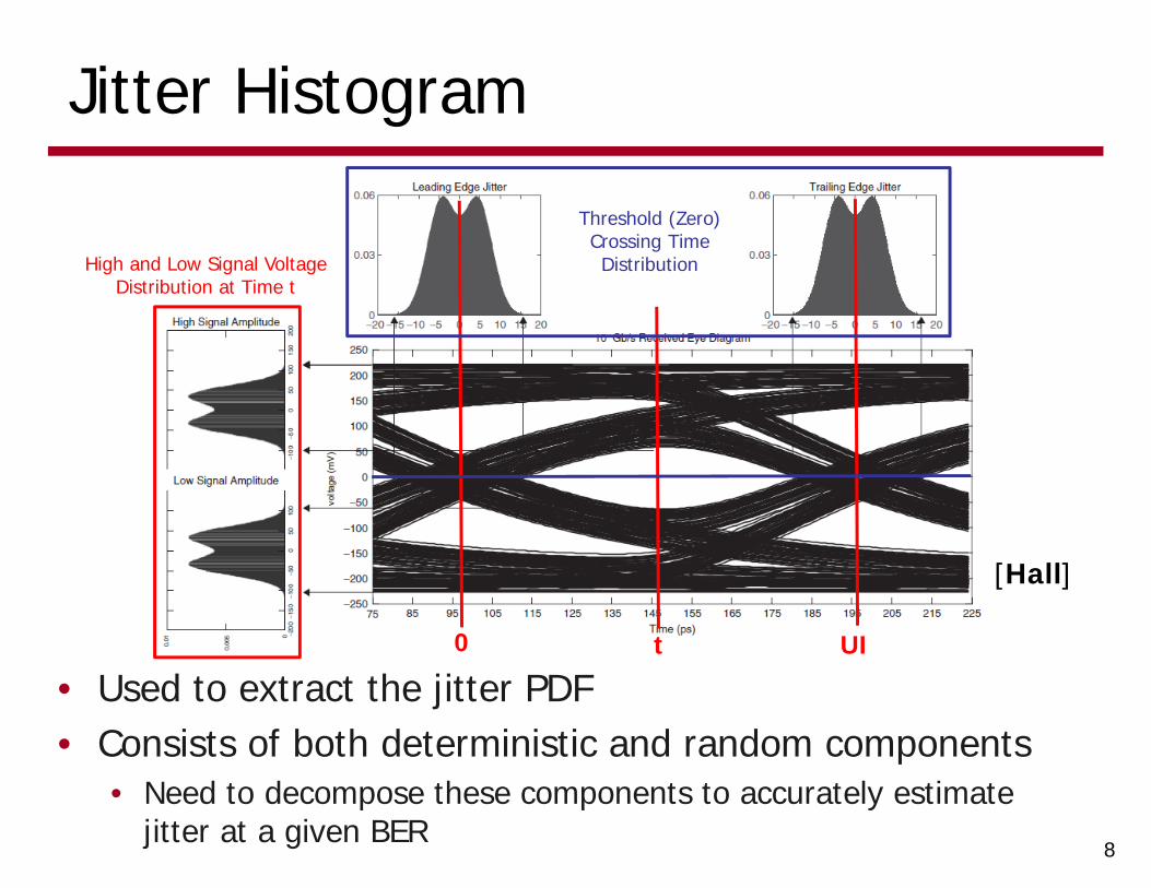
Jitter Histogram
• Used to extract the jitter PDF• Consists of both deterministic and random components
• Need to decompose these components to accurately estimate jitter at a given BER
8
[Hall]
0 UIt
High and Low Signal Voltage Distribution at Time t
Threshold (Zero) Crossing Time Distribution
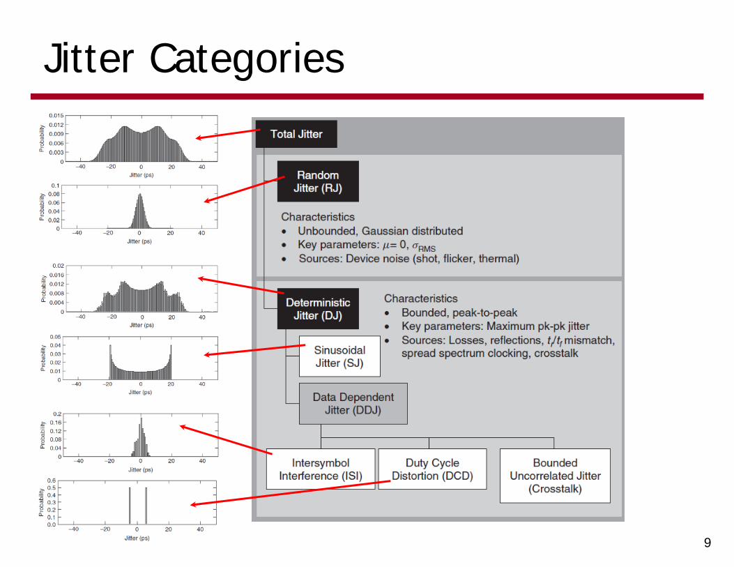
Jitter Categories
9
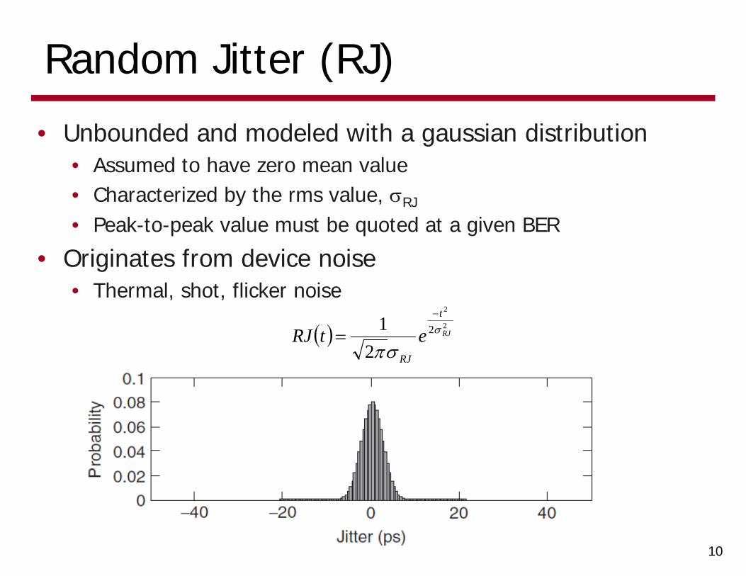
Random Jitter (RJ)
• Unbounded and modeled with a gaussian distribution• Assumed to have zero mean value• Characterized by the rms value, RJ
• Peak-to-peak value must be quoted at a given BER
• Originates from device noise• Thermal, shot, flicker noise
10
2
2
2
21
RJ
t
RJ
etRJ
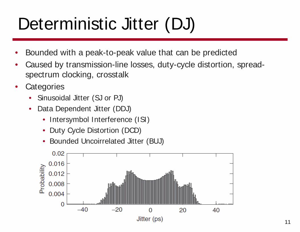
Deterministic Jitter (DJ)• Bounded with a peak-to-peak value that can be predicted• Caused by transmission-line losses, duty-cycle distortion, spread-
spectrum clocking, crosstalk• Categories
• Sinusoidal Jitter (SJ or PJ)• Data Dependent Jitter (DDJ)
• Intersymbol Interference (ISI)• Duty Cycle Distortion (DCD)• Bounded Uncoirrelated Jitter (BUJ)
11
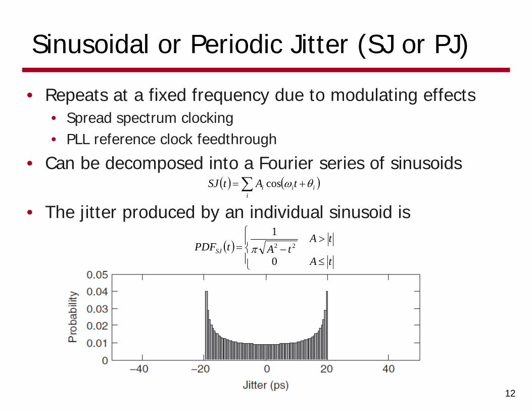
Sinusoidal or Periodic Jitter (SJ or PJ)
• Repeats at a fixed frequency due to modulating effects• Spread spectrum clocking• PLL reference clock feedthrough
• Can be decomposed into a Fourier series of sinusoids
12
i
iii tAtSJ cos
• The jitter produced by an individual sinusoid is
tA
tAtAtPDFSJ
0
122
Data Dependent Jitter (DDJ)
• Data dependent jitter is correlated with either the transmitted data pattern or aggressor (crosstalk) data patterns
• Caused by phenomena such as phase errors in serialization clocks, channel filtering, and crosstalk
• Categories• Duty Cycle Distortion (DCD)• Intersymbol Interference (ISI)• Bounded Uncorrelated Jitter (BUJ)
13
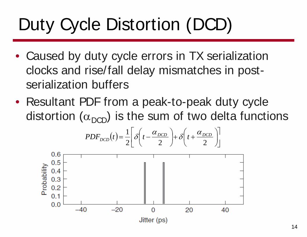
Duty Cycle Distortion (DCD)
• Caused by duty cycle errors in TX serialization clocks and rise/fall delay mismatches in post-serialization buffers
• Resultant PDF from a peak-to-peak duty cycle distortion (DCD) is the sum of two delta functions
14
2221 DCDDCD
DCD tttPDF
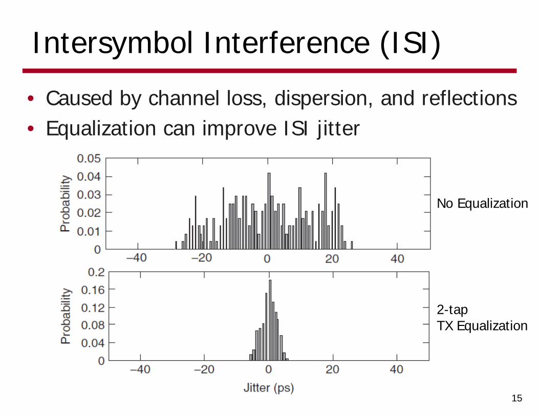
Intersymbol Interference (ISI)
• Caused by channel loss, dispersion, and reflections• Equalization can improve ISI jitter
15
No Equalization
2-tap TX Equalization
Bounded Uncorrelated Jitter (BUJ)
• Not aligned in time with the data stream
• Most common source is crosstalk
• Classified as uncorrelated due to being correlated to the aggressor signals and not the victim signal or data stream
• While uncorrelated, still a bounded source with a quantifiable peak-to-peak value
16
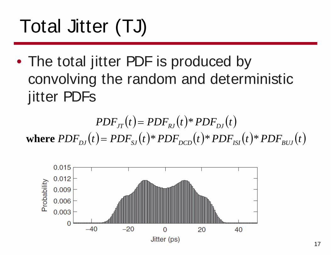
Total Jitter (TJ)
• The total jitter PDF is produced by convolving the random and deterministic jitter PDFs
17
tPDFtPDFtPDFtPDFtPDF
tPDFtPDFtPDF
BUJISIDCDSJDJ
DJRJJT
****
where
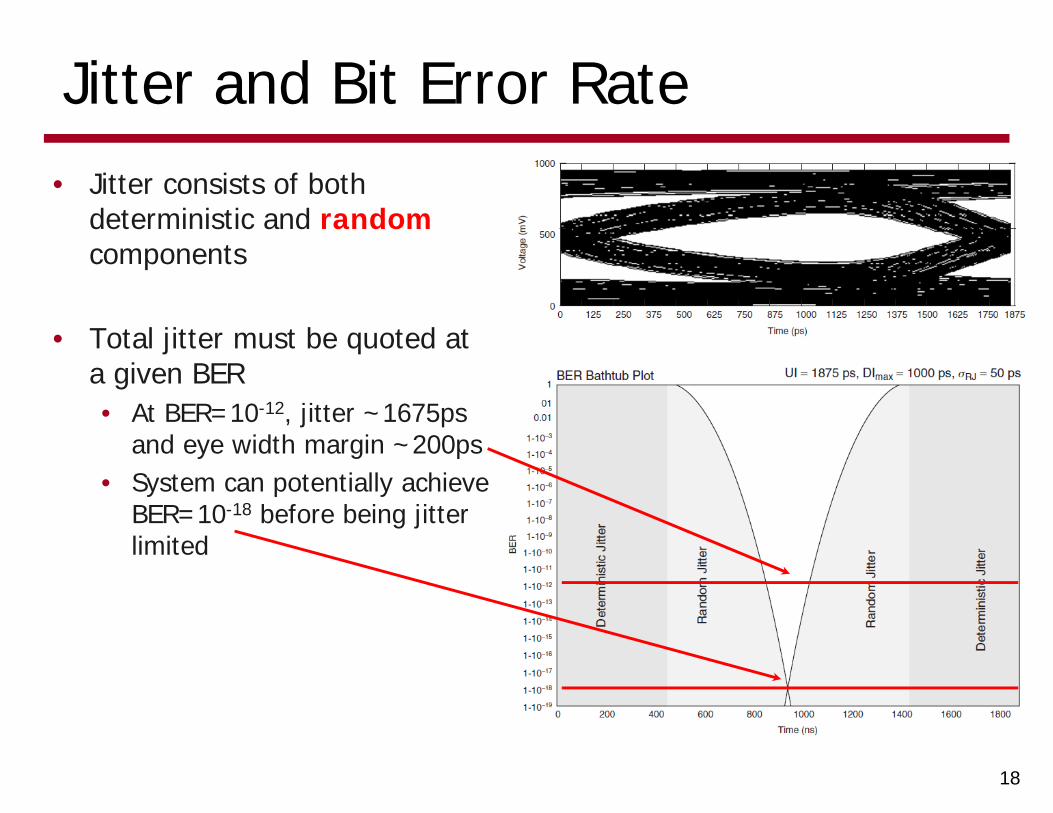
Jitter and Bit Error Rate• Jitter consists of both
deterministic and randomcomponents
• Total jitter must be quoted at a given BER• At BER=10-12, jitter ~1675ps
and eye width margin ~200ps• System can potentially achieve
BER=10-18 before being jitter limited
18
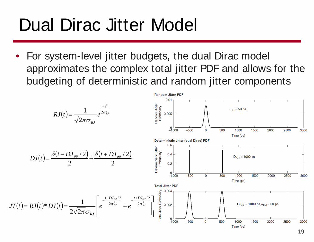
Dual Dirac Jitter Model
• For system-level jitter budgets, the dual Dirac model approximates the complex total jitter PDF and allows for the budgeting of deterministic and random jitter components
19
2
2
2
21
RJ
t
RJ
etRJ
2
2/2
2/ DJtDJttDJ
22 2
2/2
2/
221* RJRJ
DJtDJt
RJ
eetDJtRJtJT
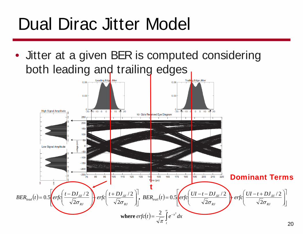
Dual Dirac Jitter Model
• Jitter at a given BER is computed considering both leading and trailing edges
20
t
x
RJRJtrail
RJRJlead
dxeterfc
DJtUIerfcDJtUIerfctBERDJterfcDJterfctBER
22
22/
22/5.0
22/
22/5.0
where
,
Dominant Termst
Dual Dirac Jitter Model Example
21
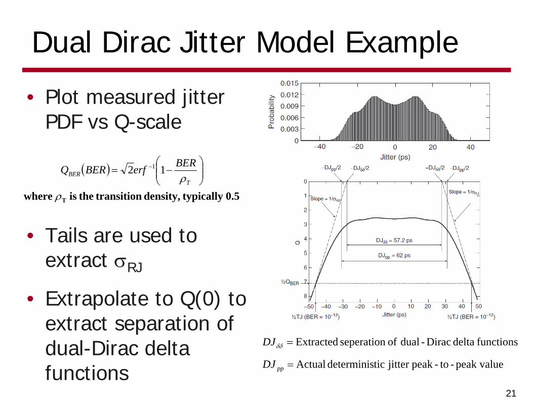
• Plot measured jitter PDF vs Q-scale
0.5 typically density, transition the is where T
TBER
BERerfBERQ 12 1
• Tails are used to extract RJ
• Extrapolate to Q(0) to extract separation of dual-Dirac delta functions peak value-to-peakjitter ticdeterminis Actual
functions delta Dirac-dual of seperation Extracted
ppDJ
DJ
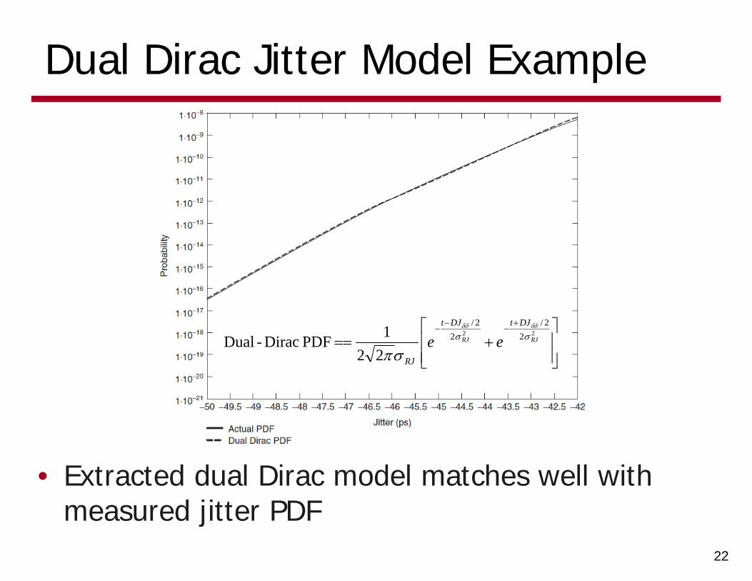
Dual Dirac Jitter Model Example
22
• Extracted dual Dirac model matches well with measured jitter PDF
22 2
2/2
2/
221PDF Dirac-Dual RJRJ
DJtDJt
RJ
ee
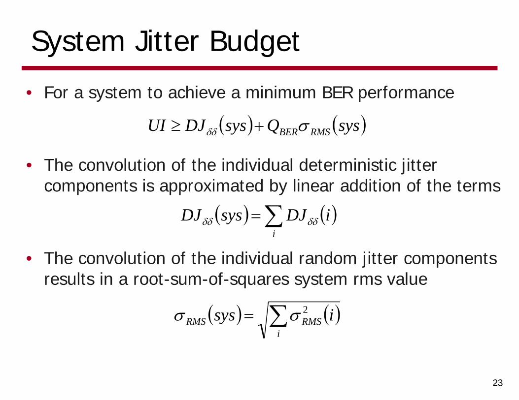
System Jitter Budget
• For a system to achieve a minimum BER performance
23
sysQsysDJUI RMSBER
• The convolution of the individual deterministic jitter components is approximated by linear addition of the terms
i
iDJsysDJ
• The convolution of the individual random jitter components results in a root-sum-of-squares system rms value
i
RMSRMS isys 2
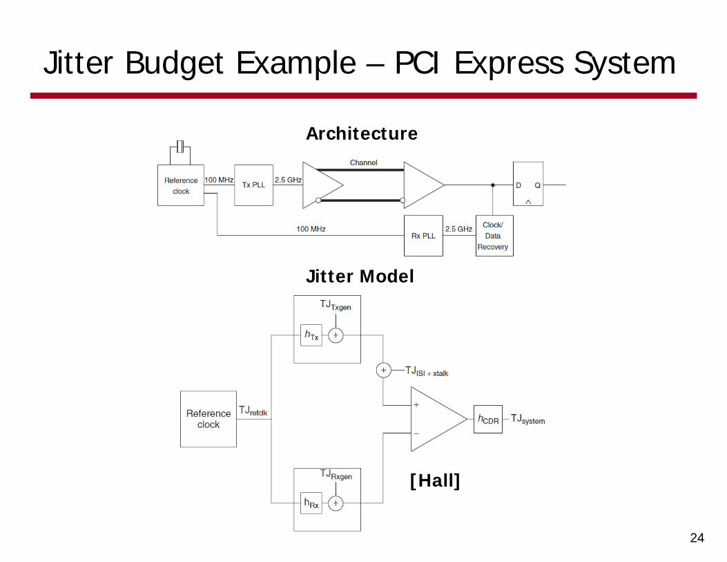
Jitter Budget Example – PCI Express System
24
Architecture
Jitter Model
[Hall]
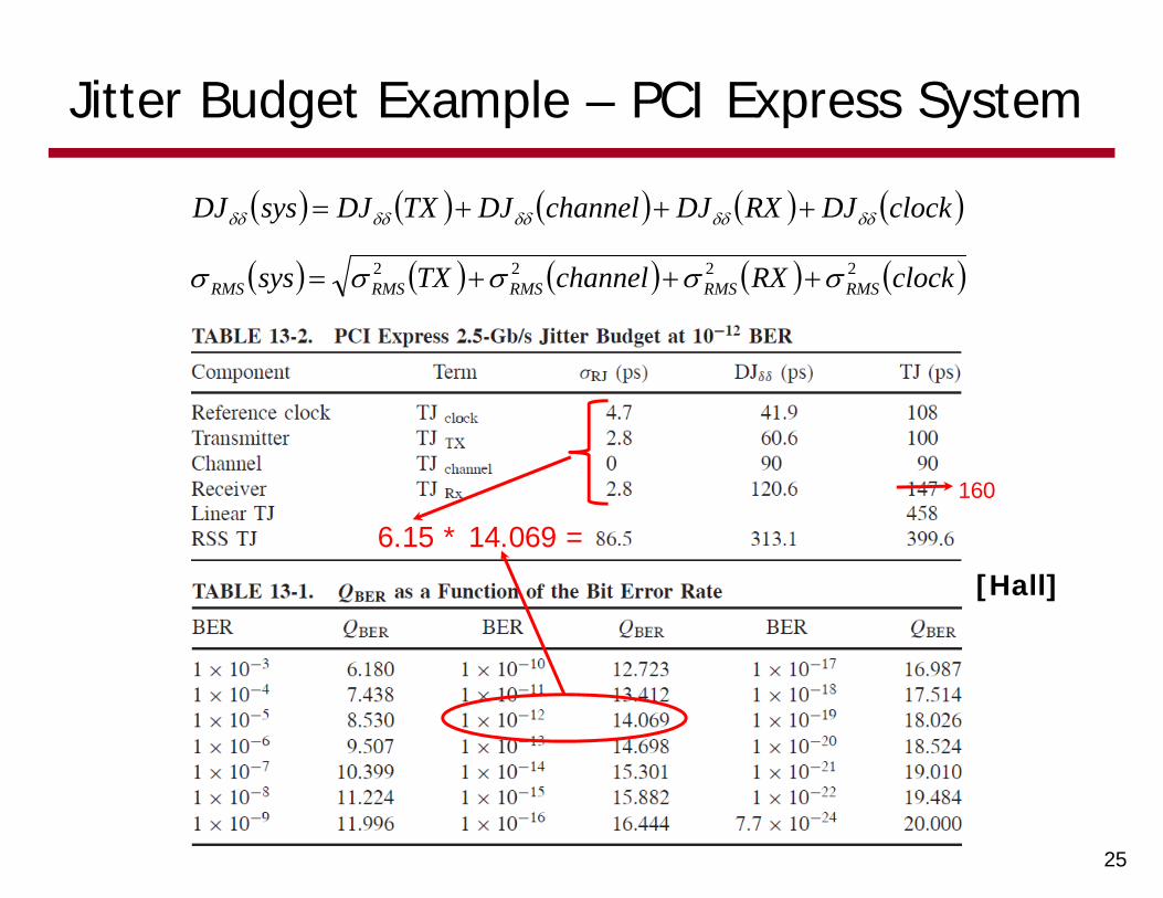
Jitter Budget Example – PCI Express System
25
clockDJRXDJchannelDJTXDJsysDJ
clockRXchannelTXsys RMSRMSRMSRMSRMS2222
6.15 * 14.069 =
[Hall]
160
Next Time
• Clocking Architectures
26