Embed Size (px)
Citation preview

ECON OIL NIGEL DEPOT NERSA LICENCES
File Description:
Application for an Operations Licence for a Petroleum Products Storage Facility
Client:
ECON Oil & Energy (Pty) Ltd
Location:
Storage Facility Operation is proposed to be commenced at ERF 1641 of NIGEL Ext 6 on Portion 36 of the farm Varkensfontein No. 169-I.R.
File Number: 1 of 1
March 2016 (Application – for Publication)

ECON OIL NIGEL DEPOT NERSA LICENCES
File Description:
Application for an Operation Licence for a Petroleum Products Storage Facility
CONTENTS
1. NERSA Form B 1.1 Chapter 1
Sections A to E of Form B, Chapter 1, completed, signed and including letter of authorisation and other attachments as applicable.
1.2 Chapter 2 Documents or Information to be submitted with a Licence Application - Information entered to address Items 1 to 17, including references to
supporting information in the appendices as applicable.
1.3 Chapter 3 Details of Application for a Licence for the Operation of a Petroleum Storage Facility - Information entered to address Items 1 to 10 of Form PPL.sf.F3
including references to supporting information in the appendices as applicable
2. APPENDICES
Appendices 1 to 19


FORM B
FORM B Applications for a licence in terms of the Petroleum Pipelines Act, 2003
(Act No. 60 of 2003)
INSTRUCTIONS 1. Prior to completing this form, you are advised to read the following documents:
(a) the Petroleum Pipelines Act, 2003 (Act No. 60 of 2003) and its Regulations; and
(b) the Rules made in terms of the Petroleum Pipelines Act specifically Rules 1 to 11.
2. Please note that this form has three chapters and that applicants must provide all information and supporting documentation required. Incomplete applications will not be accepted.
3. The completed form with supporting documentation must be delivered to the Energy Regulator: (a) by registered mail to: P O Box 40343, Arcadia 0007; or (b) by hand at: Kulawula House, 526 Madiba Street, Arcadia, Pretoria; or (c) electronically to [email protected]; or (d) by fax to 012 401 4700
4. If you want to request the confidential treatment of certain information in your application, you must make the request in accordance with Rule 4 of the Rules made in terms of the Petroleum Pipelines Act.
Enquiries: Contact: Executive Manager: Petroleum Pipelines Regulation Contact no.: (012) 401 4600 Fax no.: (012) 401 4700
Official Use Only
Date received ______________________________ Reference number ______________________________

2
CHAPTER 1 GENERAL INFORMATION
You are required to provide the following information:
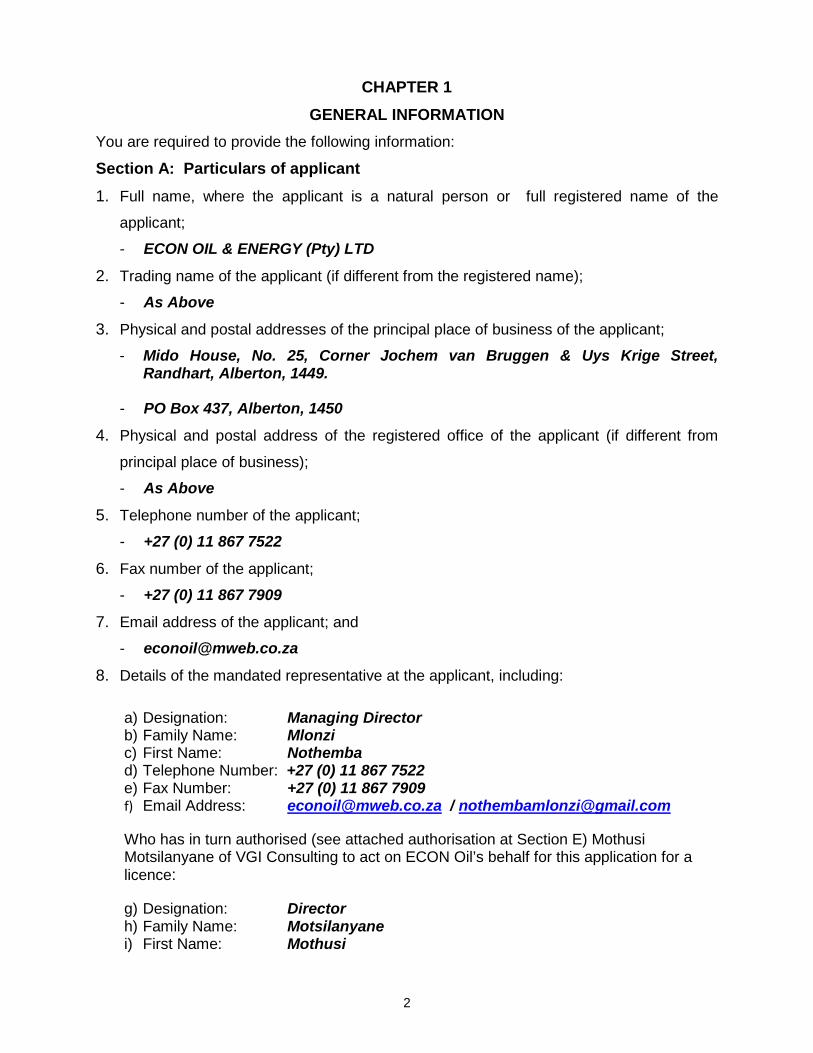
Section A: Particulars of applicant 1. Full name, where the applicant is a natural person or full registered name of the
applicant;
- ECON OIL & ENERGY (Pty) LTD
2. Trading name of the applicant (if different from the registered name);
- As Above
3. Physical and postal addresses of the principal place of business of the applicant;
- Mido House, No. 25, Corner Jochem van Bruggen & Uys Krige Street, Randhart, Alberton, 1449.
- PO Box 437, Alberton, 1450
4. Physical and postal address of the registered office of the applicant (if different from
principal place of business);
- As Above
5. Telephone number of the applicant;
- +27 (0) 11 867 7522
6. Fax number of the applicant;
- +27 (0) 11 867 7909
7. Email address of the applicant; and
8. Details of the mandated representative at the applicant, including:
a) Designation: Managing Director b) Family Name: Mlonzi c) First Name: Nothemba d) Telephone Number: +27 (0) 11 867 7522 e) Fax Number: +27 (0) 11 867 7909 f) Email Address: [email protected] / [email protected]
Who has in turn authorised (see attached authorisation at Section E) Mothusi Motsilanyane of VGI Consulting to act on ECON Oil’s behalf for this application for a licence:
g) Designation: Director h) Family Name: Motsilanyane i) First Name: Mothusi

3
j) Telephone Number: +27 (0) 12 682 9140 k) Fax Number: +27 (0) 12 665 1718 l) Email Address: [email protected] / [email protected]
Section B: Desired commencement date Desired commencement date of the licence applied for;
- The desired commencement dates for the Operation Licence applied for herein are:
- February 2018 – for the first phase including the first 10,000,000 litres of storage capacity and all process, utility and safety systems required for the commissioning and operation.
- March 2019 – for the second phase including the second 10,000,000 litres of storage capacity and tie-ins to the process, utility and safety systems completed in the first phase.
Section C: Additional information Provide any other information relevant to this application:
- For additional information, refer to the information submitted as required by Chapters 2 & 3 for Form B
- Note that the desired commencement dates allow for the 4 – 6 month timeframe for the processing of the application and assumes that all required design and engineering work will be completed within the 6 month timeframe, thereafter allowing for two construction periods, the first starting in June 2016 and the two construction phases totalling a period of 30 months.
- This will allow for completion, commissioning and operation of the first phase for a brief period to ensure all is operating satisfactorily and then the completion of construction of the second phase.
- Note that the construction will proceed in two phases, with the first phase will completing the first 10,000,000 litres of storage capacity as well as all process utility and safety systems to allow the first phase to be commissioned and put in to operation.
- The second phase will complete the second 10,000,000 litres of storage capacity and tie in the second phase process, utilities and safety systems to planned purpose-made tie-in connections that will allow tie-ins to be completed with no disruption to operations of the first phase.
- The conditions of the licence must recognise and allow for this phased approach and allow the first phase to be put into operation and the second phase to be constructed as contemplated such that there is no need for an amendment to the licence to be applied for prior to commissioning and operating the second phase.

4
Section D: Licence conditions State your desired licence conditions in terms of section 20(1) of the Act.
- Section 20(1) of the Act (the Petroleum Pipelines Act, 2003 (Act 60 of 2003)) refers and is noted that:
- Section 20(1) (f, g, h, i, j, k, l & m)) – are not applicable because the proposed facility, as presently envisaged, will be a storage facility only, with no connection to a pipeline, no shipping or (ship)loading activities or facilities.


6
CHAPTER 2
DOCUMENTS OR INFORMATION TO BE SUBMITTED WITH A LICENCE APPLICATION
1. If the applicant is a natural person and a South African citizen, a certified copy of the
applicant’s identity document.
2. In the case of a non-South African citizen, a certified copy of her/his:
(a) passport;
(b) permanent residence permit or employment permit; and
(c) proof of residence in South Africa, or proof of domicile in South Africa.
3. If the applicant is:
(a) a national, provincial or local government;
(b) another statutory body;
(c) a juristic person established in terms of an Act of Parliament; or
(d) a company or other legal body established by statute or government
directive,
state the proclamation or legislation establishing such a body. 4. If the applicant is not a natural person, and is not contemplated in 3 above provide -
(a) the title of legislation under which it is registered;
(b) the registration number given to it in terms of such legislation;
(c) other details relating to the entity; and
(d) any other information the Energy Regulator may require.
5. Where the applicant is a company provide:
(a) certified copy of the certificate of incorporation;
Please refer to Appendix 1
(b) the names of current directors; and
Please refer to Appendix 2
(c) details regarding the ownership or shareholding structure, including
particulars of the shareholders;
Please refer to Appendix 3

7
6. Where the applicant is a Trust as defined in the Trust Property Act, 1988 (Act No. 57
of 1988), provide:
(a) a certified copy of the trust deed or trust instrument and in the event of
same having been amended, copies of the amended page(s) duly
certified;
(b) Letters of Administration duly certified, issued to the trustees, and if this
document has been amended, then a copy of the current Letters of
Administration duly certified;
(c) certified copies of the identity documents of the trustees and beneficiaries
and proof of each one's residential address;
(d) proof of the address at which the Trust is conducting its business such as
an account of the local authority for rates, taxes, electricity or water which
should reflect the physical address of the Trust; and
(e) a resolution of the trustees authorising any one or more of them to apply
for the licence which reflects the names of the trustees that attended this
meeting and each one's vote for or against the resolution.
7. Where the applicant has authorised another person to submit the licence application
on its behalf, documentary proof of authorisation and a certified copy of the identity
document of the mandated/ authorised representative of the applicant.
- Please refer to Appendix 4 for proof of authorisation and a certified copy of the identity document of the mandated representative of the applicant.
8. Proof that the applicant is the owner of the petroleum pipeline, storage facility or
loading facility.
- Noting the facility is not yet constructed, please refer to Appendix 5 for proof of ownership of the land on which it is proposed to construct the storage facility.
9. Where the owner of the petroleum facility is not the owner of the land on which the
facility is situated, proof that the applicant is the owner of the petroleum facility and
proof of authorisation to use the land.
10. Where the facility is owned by more than one person, the applicant must provide –
(a) details of the co-ownership and documentary proof thereof or a solemn
declaration to that effect; and


9
(ii) a solemn declaration outlining the applicant’s plans and ability to
comply with all applicable labour, health and environmental
legislation;
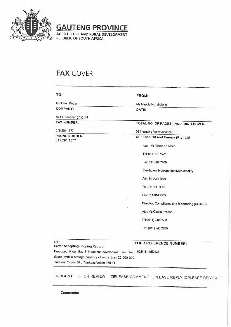
In respect of 14(a), please refer to Appendix 9 and the letter received from Gauteng Province, Department of Agriculture and Rural Development whereby the Scoping Report and Plan of Study for the Environmental Impact Assessment (EIA) has been accepted by said department. The letter’s reference number is: Gaut 002/012-13/E0234 and the letter is dated 20th May 2014. Further please note that the EIA is being conducted by AGES Limpopo (Pty) Ltd who have been contracted by ECON OIL & ENERGY (Pty) Ltd to conduct this EIA.
or
(b) state reason why the permit is not applicable.
15. List all applicable:
(a) legislation;
(b) operating and technical standards; and
(c) codes and specifications (including those relating to safety) to be used in
the activities for which this application is made, for example:
(i) South African National Standards (SANS)
(ii) the American Society of Mechanical Engineers (ASME) Standards;
(iii) American Petroleum Institute (API) Standards; and
(iv) European Norms (EN).
With regard to 15.a), b) and c), please refer to the documentation provided in Appendix 10, this documentation was developed as part of the engineering feasibility study and cost estimation package prepared for ECON OIL & ENERGY (Pty) LTD by VGI Consulting and provides details of the legislation, codes and standards applicable to the design, engineering, construction and operation of the proposed storage facility.
16. Provide details of the petroleum that will be handled in the facility for which this
application is made.
Please refer to the documentation provided in Appendix 10 and specifically the document, 1123 Design Basis Rev 01, Section 2, Table 1
17. Provide information required by Regulations made in terms of the Act concerning

10
mechanisms to promote historically disadvantaged South Africans.
Please refer to Appendix 11, but also note that ECON OIL & ENERGY (Pty) LTD has, as its managing director, Mrs Nothemba Rossette Mlonzi. Please also refer to ECON Oil & Energy’s website at www.econoil.co.za and in particular, the information posted on the website with respect to “About Us”, “Our Team” and “Social Development”.


11
CHAPTER 3 - DETAILS OF APPLICATION (Complete the appropriate form): Petroleum Pipelines
- Construction of a petroleum pipeline (PPL.p.F1)
- Conversion of a petroleum pipeline (PPL.p.F2)
- Operation of a petroleum pipeline (PPL.p.F3)
Petroleum Storage Facilities - Construction of a petroleum storage facility (PPL.sf.F1)
- Conversion of a petroleum storage facility (PPL.sf.F2)
- Operation of a petroleum storage facility (PPL.sf.F3)
Petroleum Loading Facilities - Construction of a petroleum loading facility (PPL.lf.F1)
- Conversion of a petroleum loading facility (PPL.lf.F2)
- Operation of a petroleum loading facility (PPL.lf.F3)
Note from the applicant’s mandated representative – The form PPL.sf.F3, applicable to a licence application for the operation of a petroleum storage facility, has been completed below, all other, non-applicable, forms have been deleted for clarity.

12
OPERATION OF A PETROLEUM STORAGE FACILITY (PPL.sf.F3) Provide the following information/documentation. Each numbered item below should be
copied and appear at the top of a page with your information below.
1. A technical description of the proposed storage facility to be constructed. This
should include the following -
(a) the physical address;
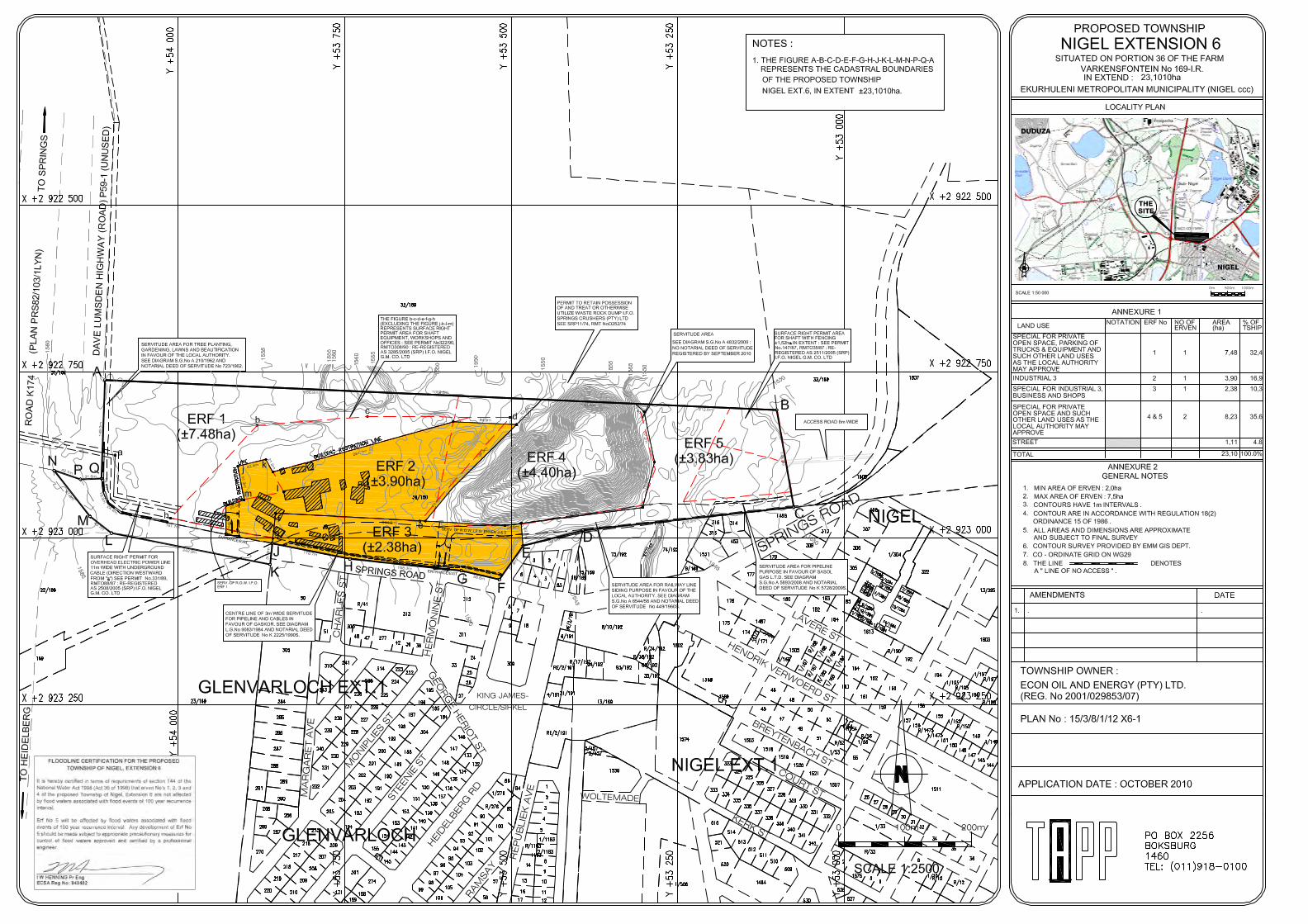
ERF 1641 (formerly ERF 02) on Portion 36 of Varkenfontein No 169-I.R. Nigel, Gauteng 002/13-14/E0234. See also Plans Nos. 15/3/8/1/12 X6-1 & 3 provided in Appendix 12.
(b) GPS Coordinates;
Entrance of Springs Road is at: 26° 24’ 55.83” South x 28° 27’ 34.20” East. Altitude is 1564m (a.m.s.l). Please refer to Appendix 13 and the Google Earth view with GPS coordinates.
(c) a plan layout of the proposed facility;
Please refer to drawing 1123-C-A1-02102 Phase 1 & 2 Layout. The drawing is provided in Appendix 14.
(d) the diameter and height of the tanks;
Please refer to the spread-sheet 1123 ECON – Tank Capacities Details Rev 03 and the Tanks Data Sheets provided in Appendix 15.
(e) tank type;
Tanks will be aboveground, vertical, steel, field erected storage complying with API 650 and aboveground, vertical, steel, shop-fabricated tanks generally complying with ASME VIII Division 1 (RSA CIF 8.1).
(f) tank identification number;
Please refer to the spread-sheet and tank data sheets provided at 1d and also to the drawing 1123-C-A1-02102 Phase 1 and 2 Layout provided at 1c.
(g) operational capacity;
Please refer to the spread-sheet and tank data sheets provided at 1d
(h) design capacity;
Please refer to the spread-sheet and tank data sheets provided at 1d
(i) product to be stored in each tank;
13
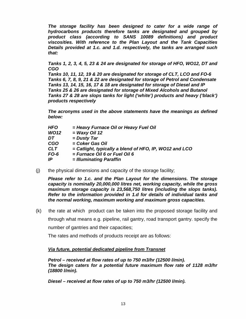
The storage facility has been designed to cater for a wide range of hydrocarbons products therefore tanks are designated and grouped by product class (according to SANS 10089 definitions) and product viscosities. With reference to the Plan Layout and the Tank Capacities Details provided at 1.c. and 1.d. respectively, the tanks are arranged such that: Tanks 1, 2, 3, 4, 5, 23 & 24 are designated for storage of HFO, WO12, DT and CGO Tanks 10, 11, 12, 19 & 20 are designated for storage of CLT, LCO and FO-6 Tanks 6, 7, 8, 9, 21 & 22 are designated for storage of Petrol and Condensate Tanks 13, 14, 15, 16, 17 & 18 are designated for storage of Diesel and IP Tanks 25 & 26 are designated for storage of Mixed Alcohols and Butanol Tanks 27 & 28 are slops tanks for light (‘white’) products and heavy (‘black’) products respectively The acronyms used in the above statements have the meanings as defined below: HFO = Heavy Furnace Oil or Heavy Fuel Oil WO12 = Waxy Oil 12 DT = Dusty Tar CGO = Coker Gas Oil CLT = Catlight, typically a blend of HFO, IP, WO12 and LCO FO-6 = Furnace Oil 6 or Fuel Oil 6 IP = Illuminating Paraffin
(j) the physical dimensions and capacity of the storage facility;
Please refer to 1.c. and the Plan Layout for the dimensions. The storage capacity is nominally 20,000,000 litres net, working capacity, while the gross maximum storage capacity is 23,568,750 litres (including the slops tanks). Refer to the information provided in 1.d for details of individual tanks and the normal working, maximum working and maximum gross capacities.
(k) the rate at which product can be taken into the proposed storage facility and
through what means e.g. pipeline, rail gantry, road transport gantry. specify the
number of gantries and their capacities;
The rates and methods of products receipt are as follows:
Via future, potential dedicated pipeline from Transnet Petrol – received at flow rates of up to 750 m3/hr (12500 l/min). The design caters for a potential future maximum flow rate of 1128 m3/hr (18800 l/min). Diesel – received at flow rates of up to 750 m3/hr (12500 l/min).

14
The design caters for a potential future maximum flow rate of 1128 m3/hr (18800 l/min). Via Road Tanker Off-loading Road-tanker off-loading will be done at dedicated off-loading bays located along the main access road running through the tank farm between the Phase 1 and Phase 2 portions of the facility. Petrol and Condensate: 3 dedicated off-loading stations in 1 off-loading bay. Off-loading flow rate will be 84 m3/hr (1400 l/min). Diesel and Illuminating Paraffin: 3 dedicated off-loading stations in 1 off-loading bay. Off-loading flow rate will be 84 m3/hr (1400 l/min). HFO, WO12, DT, CGO & FO-6: 3 dedicated off-loading stations in 1 off-loading bay. Off-loading flow rate will be 60 m3/hr (1000 l/min). LCO and CLT: 3 dedicated off-loading stations in 1 off-loading bay. Off-loading flow rate will be 60 m3/hr (1000 l/min). Butanol/Mixed Alcohols: 1 dedicated off-loading station in 1 off-loading bay. Off-loading flow rate will be 84 m3/hr (1400 l/min). Slops (light (‘white’) products): 1 dedicated off-loading station. Off-loading flow rate will be 84 m3/hr (1400 l/min). Slops (heavy (‘black’) products): 1 dedicated off-loading station. Off-loading flow rates will be 60 m3/hr (1000 l/min). Both slops off-loading stations are in the same bay. In summary, for receiving products via off-loading from road tankers there are 15 off-loading stations, located in 6 off-loading bays
(l) the rate at which product can be taken out of the proposed storage facility and
through what means e.g. pipeline, rail gantry, road transport gantry. specify the
number of gantries and their capacities
Via Road Tanker Loading All products shall be despatched via road tankers. A single road tanker loading gantry is to be constructed and will provide for 4 loading bays. Bays 1 & 2 will be dedicated to the heavy ‘black’ products and Bays 3 & 4 will be dedicated to the light ‘white’ products.

15
The current design allows for up to 6 loading arms per loading bay, although initially only 4 loading arms per loading bay may be commissioned. Loading Gantry Bays 1 & 2 Bays 1 and 2 will cater for the loading and despatch of HFO, WO12, DT, CGO, FO-6, LCO and CLT Loading flow rate will be 60 m3/hr (1000 l/min). Each of Bays 1 & 2 will have 6 loading arms, 1 for each product, noting that CGO and DT will share one loading arm in each bay Loading Gantry Bays 3 & 4 Bays 3 and 4 will cater for the loading and despatch of Petrol, Condensate, Diesel, Illuminating Paraffin and Butanol/Mixed Alcohols. Loading flow rate will be 84 m3/hr (1400 l/min) Each of Bays 3 & 4 will have 6 loading arms. Bay 3 will have: - 1 loading arm for Butanol/Mixed Alcohols - 2 loading arms for Petrol - 2 loading arms for Diesel - 1 loading arm for IP Bay 4 will have: - 1 loading arm for Butanol/Mixed Alcohols - 2 loading arms for Petrol - 2 loading arms for Diesel - 1 loading arm for Condensate
(m) maps showing –
(i) the storage facility design and piping arrangements;
Please refer to the drawing(s) in Appendix 16.
(ii) the proposed location of the storage facility, fences and roads;
Please refer to the drawing(s) in Appendix 17.
(iii) where applicable, a description of the containment system and systems to
prevent overflow or leakage;
Please refer to the drawing(s) in Appendix 18 and also to the documentation provided in Appendix 10.
(iv) a description of the regular inspection and maintenance procedures;
Please refer to the engineering documentation provided in Appendix 10, but note that the facility has not yet been constructed and appropriate

16
inspection and maintenance procedures still need to be developed once equipment has been finalised, constructed, erected, assembled and installed. That said, periodic, regular maintenance procedures will be developed for daily, weekly, monthly, yearly and 3 or 5 yearly inspections as per the recommendations of the original equipment manufacturers/suppliers and as mandated by the relevant requirements of the OHS Act, the PER and relevant SANS, API and ASME codes and standards. For example, all pressure relief and safety relief devices shall as a minimum be calibrated and set immediately before commissioning and every 36 months thereafter. Atmospheric storage tanks shall be inspected in accordance with the requirements of their codes of design and construction, i.e. API 650 / 653 and ASME VIII Div 1 as applicable.
(v) and where applicable, a description for handling contaminated water run-
off.
Please refer to the engineering documentation provided in Appendix 10. Also note that all tanks, pumps and operating process equipment will be installed in bunded or kerbed containment areas in line with requirements of SANS 10089-1. These containment areas shall be connected to the oily water sewer system and provide with isolation valves which will remain closed in normal operation. Spillage in the containment areas will be cleaned by a specialist contractor with remaining traces of spillages being washed away to the oily water sewer and thence to the oil-water separator. Cleaned water from the separator will be sample to ensure compliance with the requirements of the Water Quality Act prior to release to the storm water system. The off-loading bays and the loading gantry area will also be provided with drainage channels and connections to the oily water sewer system. Clean paved areas not subject to process spillages shall be contoured to ensure run-off is directed away from potentially contaminated areas and thence to the storm water sewer system. Please refer to the drawings in Appendix 18 that are provided in respect of Item m) (iii).
2. Election of third party access to uncommitted capacity arrangements as
contemplated in section 20 (1) (n) of the Act.
In terms of Section 20 91) (n) of the Petroleum Pipelines Act (Act No. 60 of 2003), third parties must in the manner prescribed by regulation have access on

17
commercially reasonable terms to uncommitted capacity in storage facilities. Provided that an applicant for a storage facility licence or an amendment of such a licence may elect to give users access to the facility on the basis that the capacity is shared among all users in proportion to their needs. In this regard, ECON Oil (Pty) Ltd intends that the storage capacity is to be split approximately 20% for ECON Oil (Pty) LTD own use and 80% for other users (ECON Oil (Pty) LTD’s customers). An appropriate tariff for storage of third parties’ products will be calculated and approval from NERSA for such tariff will be applied for in accordance with the Act and the Rules and in terms of NERSA’s legal mandate.
3. Provide information required in terms of rules 12(7) and 12 (8) of these Rules.
In terms of the Rules Made In Terms of Section 33(3) Petroleum Pipelines Act, 2003 (Act No. 60 of 2003), Rule 12(7) and 12(8) refer and it is noted: 12(7) (c) (i) – is with respect to the proposed tariffs for storage facilities and is noted that attempts were made to use the NERSA Calculation Methodology as available from the NERSA website. However it is noted that difficulty was experienced with the excel file and it did not appear to be updating correctly, there seemed to be issues with the links. In discussions, ECON OIL & ENERGY have advised that they propose a tariff to be charged for storage of hydrocarbon products at this new facility of 9 (nine) cents per litre per day. This tariff is proposed on the basis that this is what ECON OIL & ENERGY (Pty) LTD themselves are currently charged for storage of their products at other current facilities and is considered by ECON OIL & ENERGY (Pty) LTD to be a minimum tariff. It is understood that NERSA will use their latest current methodology to calculate a tariff and evaluate this proposal. 12(8) – is with respect to the proposed tariff and basis for the proposal and relates to additional information that may be requested by NERSA. In this respect, ECON OIL & ENERGY (Pty) Ltd, undertakes to provide any additional information which NERSA may reasonably request during the Licence Application evaluation and approval process.
4. A copy of the emergency plan contemplated in section 20(1) (x) of the Act.
The emergency plan is still to be developed during the basic engineering phase of the project. 5. A copy of the intended storage facility operational procedures.
Operational Procedures are still to be developed during the detailed engineering and execution phases of the project, however, for a high level description of the


20
APPENDICES Appendix 1 – Certified Copy of the Certificate of Incorporation of ECON Oil & Energy (Pty) Ltd Appendix 2 – List – Names of the Current Directors of ECON Oil & Energy (Pty) Ltd Appendix 3 – Details – Ownership and/or Shareholding Structure Appendix 4 – Proof of Authorisation (appointment) of VGI Consulting to submit the application Certified copy of the identity document of VGI Consulting’s representative Appendix 5 – Proof of Ownership of the Storage Facility Appendix 6 – Documents demonstrating the administrative abilities of the applicant Appendix 7 – Documents demonstrating the financial abilities of the applicant Appendix 8 – Documents demonstrating the technical abilities of the applicant Appendix 9 – Gauteng Agriculture and Rural Development Letter (approval of EIA Scoping Report) Appendix 10 – Documentation Submitted in respect of Chapter 2, 15 & 16
Appendix 11 – Mechanisms for the Promotion of Historically Disadvantage South Africans
Appendix 12 – Plan No. 15/3/8/1/12 X6-1 & 3 appended in respect of Chapter 3, 1. a) Appendix 13 – Google Earth View GPS Coordinates appended in respect of Chapter 3, 1. b) Appendix 14 – Site Layout, Drawing 1123-C-A1-02102 appended in respect of Chapter 3, 1. c) Appendix 15 – 1123-ECON - Tank Capacities Details Rev 03 Spread-sheet and Tanks Data Sheets
appended in respect of Chapter 3, 1. d) Appendix 16 – Drawings 1123-C-A1-01101 and 01102, the process piping and fire protection piping
layouts appended in respect of Chapter 3, 1. m) (i) Appendix 17 – Drawings 15_02/01 GL – 102 and 003, the security fences and roads layouts appended
in respect of Chapter 3, 1. m) (ii) Appendix 18 – Drawings 15_02/01 GL – 005, 004, the containment bunds, oily water sewer
layouts and storm water sewer layout, appended in respect of Chapter 3, 1 m) (iii) Appendix 19 – Document 1123 Operating Philosophy Rev 01, appended in respect of Chapter 3, 7.


COMPANY PROFILE
to generate energy for an equitable economy

Welcome to Econ Oil & Energy
Founded in 2001, Econ Oil is proud to be a pioneer in industrial energy provision with innovative
approach to its customers.
Econ Oil, is a privately black women owned business which offers fuel oil storage, fuel, automotive fuels,
LPG, Industrial energy solutions, laboratory services and fuel management system to its customers.
It supplies fuel oil for generation, mining, tyre, milling and other industries.
In response to the energy demand in our country Econ Oil offers off the grid energy solutions to
industries, office buildings, malls, hospitals and other entities which have high energy consumption.
Econ Oil produces its own fuel oil that is environmentally friendly and free of minerals according to
customer needs from its Marble Hall Blending Plant.
In its enterprise development initiatives the company is mentoring energy fuel transporters and has
developed a franchised mobile kitchen to develop a unique brand of SMME’s.
The company is committed to social upliftment and to this end has a programme which is running for
5 years now in developing careers of children from rural background by so doing cutting the cycle of
poverty.
It has also adopted a rural school and provided the school with a computer laboratory with 25
computers. Needless to mention the computer laboratory is now used by the district providing learners
with computer skills. Also built a library for the same school.
Training, the company provided training to about 20 youth in Marble Hall equipping them with business
skills.
01
VISION
To advance product development, marketing and distribution of energy products in Southern Africa.
MISSION
To grow an empowered progressive business in the energy sector in servicing customers promptly,
effectively and efficiently.
VALUES
Partnership
Respect
Customer Service Response
Ethical Practices
Accountability
02

FUEL OIL SUPPLY
Econ Oil is registered with the Department of Minerals and Energy holding a wholesale licence in terms
of the Petroleum Products Act, 1977 (Act No. 120 of 1977).
Econ Oil has since its establishment modelled a business platform on solid relationship with established
oil majors in South Africa to ensure both the security and quality of supply to its customers.
This ensures that the company is able to supply and deliver whoever in South Africa.
The company has 80% the volume of all its products in Gauteng and the rest, in various provinces in
the country. This model increases our flexibility of supply and allows us to grow our business in
accordance with our customers demand.
03

WE SUPPLY THE FOLLOWING PRODUCTS
CATLIGHT
Catlight is an environmental friendly, cost effective, low sulphur fuel suitable for larger applications that require a
clean and light fuel and is mostly suitable for small burners.
LCO
LCO is cost effective, high sulphur content compared to diesel and illuminating paraffin, however this product
can be used as the replacement for catlight, illuminating paraffin and diesel but only as the burner oil not as
automotive fuel
ECBFO and FO6
These products can be used mainly on the higher density environment and low sulphur. Small burners are
relatively suitable for these products.
HFO 150 / 180
HFO 150 / 180 is mainly used on the larger boilers, however it consists of larger particles of aluminium, high
sulphur, and high ash content. Some burners might struggle to burn the product.
ILLUMINATING PARAFFIN
This product is clear, free from water suspended matter, sediment and other impurities. It can also be used as the
industrial and home heating fuel. It has a low viscosity and low flashpoint.
JET FUEL
Jet fuel is a clear to straw-coloured fuel, based on either an unleaded kerosene (Jet A-1), or a naphtha-kerosene
blend (Jet B). It is similar to diesel fuel, and can be used in either compression ignition engines or turbine engines
AUTOMOTIVE FUELS
Diesel 500
Diesel 50 ULS
Petrol 95 ULP
Petrol 93 LRP/ULP
LPG
This product is available in bulk and mainly sold for resellers and high volume Customers for refilling.
LUBRICANTS
Industrial lubricants are basically defined as compounds like fluids, greases and oils. They are used in order to
lessen wear and tear of materials while reducing binding and friction. We supply high volume customers with
lubricants.
04

STORAGE FACILITIES
ERMELO, MPUMALANGA
Econ Oil & Energy (Pty) Ltd purchased the million litre terminal located at Ermelo, Mpumalanga.
The tanks have been redesigned to store, load and offload HFO 150 and light oils.
90% of the storage capabilities is leased to the industry, 10% of capacity is for holding stock for our
customers.
The terminal has a rail siding facilities on site comprise bulk storage tanks, distribution facilities,
warehousing and administration offices.
Location
This facility is located in the Ermelo Extension 2 industrial area, approximately 2 kilometres east of the
Ermelo CBD. 406 Little Street, Ermelo, Mpumalanga Province, South Africa.
Petroleum tanks are registered with NERSA in accordance with the Petroleum Products Act, 2003.
There is also LPG tank to be constructed on site to store and supply to resellers and high volume users
in the area.
Contact Details
Telephone Number: 011 867 7522
Fax Number: 011 867 7909
Email: [email protected]
Physical Address: 406 Little Street, Ermelo, Mpumalanga Province
Postal Address: P.O. Box 437, Alberton, 1450
Company Information
Company Registration Number: 2001/029853/07
VAT Number: 4220208864
GPS: -26.516742, 30.001897
05

STORAGE FACILITIES Continued
BETHLEHEM, FREE STATE PROVINCE
Automotive Fuel Storage Tanks
This depot is located at Baxter Street, Bethlehem, Free State Province, South Africa.
The depot is for storage and distribution of petroleum products and has the following infrastructure, 5
million litre bulk storage tanks, a truck gantry for loading and offloading, a storage warehouse, bunded
dispensing area.
Petroleum tanks are registered with NERSA in accordance with the Petroleum Products Act, 2003.
80% capacity is leased out to the industry from this depot, Econ Oil supplies commercial customers in
Lesotho and maintaining the stock levels for them.
Contact Details
Telephone Number: 011 867 7522
Fax Number: 011 867 7909
Email: [email protected]
Physical Address: Baxter Street, Bethlehem, Free State Province
Postal Address: P.O. Box 437, Alberton, 1450
Company Information
Company Registration Number: 2001/029853/07
VAT Number: 4220208864
GPS: -28.2319470, 28.299490
06

SERVICES
The company provides the following services.
Laboratory
In order to meet prescribed specification and guarantee quality of our products from our plant we have
our own in house laboratory in Marble Hall. However to test other properties we use accredited third
party laboratories. Exalia Phaahla is a Chemical Engineer that leads our laboratory services.
Products are tested as they are received and as they are
dispatched to our customers to ensure compliance with
agreed quality parameters. The company does offer a
range of services on request and the rates applicable are
provided by the Laboratory personnel.
Exalia Phaahla
071 273 5135
Fleet
Econ Oil has its own fleet that is utilised to deliver the products. This increases flexibility of supply and
reliability. By using its own fleet the company is able to cut down on the cost for the customer. The
company’s fleet is managed by Mzuvukile Klaas.
Mzuvukile Klaas
082 698 5264
Pumps & Tanks Installations
Econ Oil installs pumps and tanks to its customers to ensure efficient and smooth operations. This
allows the customer to store the volume it requires on site. This increases productive days for the
customer avoiding running dry when products is most needed
07

Telemetry System
The company provides a telemetry system to monitor levels at customer’s site. This allows Econ Oil to deliver to the customer in time. Telemetry system
management helps improve managing stock levels of supply to the customer.
Sharmaine Govender
011 867 7522
ALTERNATIVE ENERGY
Energy Demand in South Africa resulted in Econ Oil landing AvatarBlack as solution to high energy users.

AvatarBlack is uniquely positioned, with its position with major Technology Power providers to implement
AvatarBlack
AvatarBlack becomes either an alternative Provider of Electrical Power or becomes the De Facto Power Provider;
AvatarBlack provides the solution on a Usage Model (no capital outlay required) to the Landlord;
AvatarBlack manages the day to day operations of the solution on behalf of the Landlord;
Our Solution
Our PV Solution can provide on average a 20% higher energy yield in PV applications than conventional grid tied solutions;

Enterprise Development
The Kitchen
Designed to assist young entrepreneurs to enter business
area, and learn ALL the requisites of running a business.
It is Franchise like concept whereby a potential
entrepreneur identifies a spot next to an office building /
university and applies for own hawker licence.
The Kitchen is available and comes with the following;
2 Deep Freezers
2 Burner gas stoves with 2 large pots
Ice Cream Maker (Soft Serve)
2 Deep Fryers
Dough Mixer
Chicken Rotisserie
Storage Bin
Rubbish Bin
Restaurant Licence Holder – Econ Oil
Negotiated supply from various suppliers
To open from 8am to 4pm
Not to be used for catering functions
10

Social Development
Econ Oil has embarked on Social Development initiatives:
Econ Oil is making progress in creating an equitable environment for its people and developing their
full potential.
Econ Oil & Energy is committed to transformation beyond legislative compliance and this commitment
guides our corporate social investment initiatives as we embed sustainable development into every
facet of our business.
We have developed Training & Development which is aimed at continuous development and unlocks
individual potential. We do quality training by accredited providers which covers a broad range:-
Management Development
Leanerships
Foreman Development
Adult basic education and training
Membership programs on site technical training.
Econ Oil & Energy registered Econ Development Trust. The main aim of the trust is to broaden the skills
base of the black population in South Africa as is dwindling to a point of non-existence irrespective of
the obvious opportunities to advance oneself.
We identified Cabekwana Location as a destitute and poverty stricken area. It is located in Eastern
Pondoland in the small town Lusikisiki, in the Eastern Cape. We then adopted Goso Forest Junior
Secondary School at Cabekwana Location as our focus development agenda.
Since 2007 we identified pupils from Grade 8. The enigma in the area is that Grade 9 is the highest
standard achieved. The reasons for lack of advancement beyond Grade 9 are amongst others.
Lack of financial resources;
High pregnancy rate;
Incentive to migrate to bigger town for work opportunities;
Discourage by matriculants who are not adsorbed by the market;
We identified needy pupils with a balanced intellect. They are currently doing Grade 12 with
good prospects.
11

We have built 2 classrooms one as a Computer Lab and the other as a Library.
The impact is very high-education has gained its value. The impact will continue to grow as our
identified pupil show progress.
Marble Hall
12

INDUSTRY AFFILIATION
Black Business Council – Corporate
SAPIA
Head Office
Telephone Number: 011 867 7522
Fax Number: 011 867 7909
Email: [email protected]
Physical Address: Mido House, 25 Uys Krige Street, Corner Jochem van Bruggen, Randhart, 1449,
Alberton, Johannesburg, South Africa
Postal Address: PO Box 437, Alberton, 1450
GPS: -26.285937, 28.105307
Company Information
Company Registration Number: 2001/029853/07
VAT Number: 4220208864
B-BBEE Level 2 (Generic)
Wholesale License Number: W/2009/0256


FEASIBILITY OF A
FUEL STORAGE AND LOADING FACILITY FOR ECON OIL IN NIGEL
EXECUTIVE SUMMARY Rev 00
Compiled by:
VGI CONSULTING Inc. PO Box 68968, Highveld, 0169
In consultation with:
Gant Project Management (Pty) Ltd
PO Box 81317, Parkhurst, 2120
VGI Consulting ECON Oil & Energy
Description Name Capacity Signature Date Accepted By Capacity Signature Date
Author L van Wyk Project
Manager
Checked C Saxby Project
Engineer
MAY 2015

1123 - Introduction and General Information-rev 00 2
INDEX
1.1 Introduction ......................................................................................................................... 1
1.2 General Project Description ................................................................................................ 2
1.3 Fuel Depot Services ........................................................................................................... 3
1.4 Fuel Storage Capacity ........................................................................................................ 4
1.5 Legal Framework ................................................................................................................ 4
1.6 Safety, Health and Environmental Philosophy ................................................................... 5
1.7 Sparing Philosophy ............................................................................................................. 5
1.8 Operating Philosophy ......................................................................................................... 5
1.9 Cost Estimate ..................................................................................................................... 5
1123 - Introduction and General Information-rev 00 1
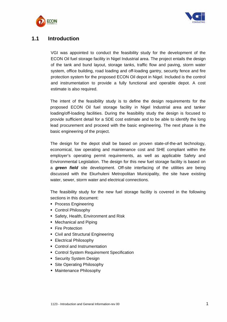
1.1 Introduction
VGI was appointed to conduct the feasibility study for the development of the ECON Oil fuel storage facility in Nigel Industrial area. The project entails the design of the tank and bund layout, storage tanks, traffic flow and paving, storm water system, office building, road loading and off-loading gantry, security fence and fire protection system for the proposed ECON Oil depot in Nigel. Included is the control and instrumentation to provide a fully functional and operable depot. A cost estimate is also required. The intent of the feasibility study is to define the design requirements for the proposed ECON Oil fuel storage facility in Nigel Industrial area and tanker loading/off-loading facilities. During the feasibility study the design is focused to provide sufficient detail for a SDE cost estimate and to be able to identify the long lead procurement and proceed with the basic engineering. The next phase is the basic engineering of the project.
The design for the depot shall be based on proven state-of-the-art technology, economical, low operating and maintenance cost and SHE compliant within the employer’s operating permit requirements, as well as applicable Safety and Environmental Legislation. The design for this new fuel storage facility is based on a green field site development. Off-site interfacing of the utilities are being discussed with the Ekurhuleni Metropolitan Municipality, the site have existing water, sewer, storm water and electrical connections. The feasibility study for the new fuel storage facility is covered in the following sections in this document: Process Engineering Control Philosophy Safety, Health, Environment and Risk Mechanical and Piping Fire Protection Civil and Structural Engineering Electrical Philosophy Control and Instrumentation Control System Requirement Specification Security System Design Site Operating Philosophy Maintenance Philosophy

1123 - Introduction and General Information-rev 00 2
1.2 General Project Description
ECON Oil & Energy plans to develop a new fuel storage facility at Nigel.
The facility will be used for storage and distribution of Econ Oil & Energy’s own products, and also to provide storage capacity for “buffer stock” or “surplus stock” for other customers to utilize so as to allow fluctuations in demand to be catered for.
The conceptual design of a bulk liquid handling and storage facility in Nigel includes connection to Transnet Pipelines, receiving manifold, storage tanks, interconnecting piping, loading and off-loading facility, heater for Heavy Fuel Oil, vapour recovery, bund walls, depot buildings, firefighting system, electrical design, control & instrumentation and security system to handle the products at the liquid bulk storage facility.
The facility will have a total fuel storage capacity of 20 000 000 liters (20 000m3), during the first phase a storage capacity of 10 000 000 liters (10 000m3) will be constructed and in a second phase, storage capacity for a further 10 000 000 liters (10 000m3) will be constructed.
Information in the conceptual design package such as; site layout, storage volumes, tank and bund sizes, spill containment, general tank design, control system, safety equipment, plant emissions / effluent handling, storm water system, oily water separator, monitoring wells and firefighting system will be used for the Environmental Impact Assessment and NERSA license application.
The fuel depot facility will be designed to receive, store and dispatch petrol (2 grades), petrol (LRP), diesel (2 grades) and fuel oil products, Waxy Oil (WO12), Illuminating Paraffin (IP), Light Cycle Oil (LCO), Heavy Furnace Oil (HFO), and the heating and dispatch thereof, Cat-Light (CL), Fuel Oil 6, Dusty Tar, Coker Gas Oil, Butanol / Mixed Alcohols and Condensate. Additive handling may also be required and the requirements for this will be investigated as part of the study.
This new ECON Oil & Energy facility is for the storage of fuel products and not a distribution depot for brand specific fuel. The storage and dosing of additives in fuel products being loaded into road tankers are very much fuel company and brand specific, with the intended use of the tanks as storage for hire, it was decided to exclude additive storage and dosing from the feasibility study.

1123 - Introduction and General Information-rev 00 3
1.3 Fuel Depot Services
The services to be allowed for as part of the new ECON Oil fuel storage depot comprises of the following salient systems: Transport Facilities:
- Road tanker off-loading facility.
- Road tanker loading gantry.
- Road tanker weigh bridge
- Emergency off-loading.
- Internal roads
Storage Facilities:
- Product storage – tank farm with capacity to store all the required products.
- Product receive from Transnet pipelines and from road tankers
- Bund walls in tank farm.
- Fuel spillage containment.
Buildings:
- Office building with a control room.
- Security buildings at the entrance / exit gate.
- Driver facilities for 24h operation.
- Fire water pump bay and reservoir.
- Electrical substation building including: MCC room, equipment room, transformer bay, generator room and compressor room.
- Associated infrastructure, internal roads and staff/visitors parking.
Ancillary Services:
- Despatch management system and metering facilities.
- Fire water provision and fire fighting system.
- Vapour recovery unit.
- Pump back blending facility (off-spec blending).

1123 - Introduction and General Information-rev 00 4
Utilities:
- Bulk electricity supply
- Standby power – diesel generator and UPS
- Instrument Air
- Potable Water
- Fire Water Supply
- Domestic Sewer
- Oily water sewer system and separator
- Telephone and data
1.4 Fuel Storage Capacity A total of twenty seven (27) storage tanks and one (1) hot product (HFO) dispatch tank are envisaged. The tanks will be of the following nominal capacities:
- 17 x 1000 m3 - 4 x 500 m3 - 5 x 200 m3 (including the hot HFO dispatch tank) - 2 x 80m3 (Slop tanks)
Material Safety Data Sheets for the main fuel products are included under Process Engineering.
1.5 Legal Framework The design of the new depot for ECON Oil & Energy, in Nigel will be undertaken with the following being complied with, as applicable:
The Employer’s Corporate Governance Policies All applicable laws, rules, regulations, standards and ordinances of South
Africa pertaining to the design of new depots and bulk storage facilities (e.g. OSH Act in South Africa or any relevant environmental acts for example National Environmental Management: Air Quality Act, )
The Employer have undertaken to complete the following studies:
An Environmental Impact Assessment (EIA). A Major Hazardous Installation (MHI) study.
ECON Oil will apply for a construction and operating license from NERSA.


EC TANK Nominal Products Working Volume Working Volume Maximum Shell Dia. Shell Ht. Outlet Outlet Invert High High High Normal Low Low LowO NO. Capacity Normal Maximum (NOTE 5) Capacity Nozzle Dia Ht above floor Level Level Fill Level Level LevelN m3 m3 m3 m3 m m in m m m m m m
1 200 HFO/WO12/DT/CGO 198.88 221.50 247.40 6.00 8.75 4.00 0.32 8.25 8.00 7.60 0.57 0.42 NOTE 72 1000 HFO/WO12/DT/CGO 1 004.64 1 075.33 1 158.46 10.00 14.75 8.00 0.46 14.25 14.00 13.50 0.71 0.563 1000 HFO/WO12/DT/CGO 1 004.64 1 075.33 1 158.46 10.00 14.75 8.00 0.46 14.25 14.00 13.50 0.71 0.564 500 HFO/WO12/DT/CGO 492.17 537.41 590.62 8.00 11.75 8.00 0.46 11.25 11.00 10.50 0.71 0.565 500 HFO/WO12/DT/CGO 492.17 537.41 590.62 8.00 11.75 8.00 0.46 11.25 11.00 10.50 0.71 0.56
23 1000 HFO/WO12/DT/CGO 1 004.64 1 075.33 1 158.46 10.00 14.75 8.00 0.46 14.25 14.00 13.50 0.71 0.5624 1000 HFO/WO12/DT/CGO 1 004.64 1 075.33 1 158.46 10.00 14.75 8.00 0.46 14.25 14.00 13.50 0.71 0.56
TOTAL CAPACITIES 5 201.79 5 597.64 6 062.49
10 1000 Catlight/LCO/FO-6 1 004.64 1 075.33 1 158.46 10.00 14.75 8.00 0.46 14.25 14.00 13.50 0.71 0.5611 1000 Catlight/LCO/FO-6 1 004.64 1 075.33 1 158.46 10.00 14.75 8.00 0.46 14.25 14.00 13.50 0.71 0.5612 1000 Catlight/LCO/FO-6 1 004.64 1 075.33 1 158.46 10.00 14.75 8.00 0.46 14.25 14.00 13.50 0.71 0.5619 1000 Catlight/LCO/FO-6 1 004.64 1 075.33 1 158.46 10.00 14.75 8.00 0.46 14.25 14.00 13.50 0.71 0.5620 1000 Catlight/LCO/FO-6 1 004.64 1 075.33 1 158.46 10.00 14.75 8.00 0.46 14.25 14.00 13.50 0.71 0.56
TOTAL CAPACITIES 5 023.21 5 376.64 5 792.31
6 1000 Petrol/Condensate 998.56 1 069.24 1 158.46 10.00 14.75 10.00 0.54 14.25 14.00 13.50 0.79 0.64 NOTE 87 1000 Petrol/Condensate 998.56 1 069.24 1 158.46 10.00 14.75 10.00 0.54 14.25 14.00 13.50 0.79 0.64 NOTE 8
IFR 8 200 Petrol/Condensate 203.97 229.42 261.54 6.00 9.25 10.00 0.54 8.75 8.50 8.00 0.79 0.64 NOTE 1IFR 9 200 Petrol/Condensate 203.97 229.42 261.54 6.00 9.25 10.00 0.54 8.75 8.50 8.00 0.79 0.64 NOTE 1
21 1000 Petrol/Condensate 998.56 1 069.24 1 158.46 10.00 14.75 10.00 0.54 14.25 14.00 13.50 0.79 0.64 NOTE 822 1000 Petrol/Condensate 998.56 1 069.24 1 158.46 10.00 14.75 10.00 0.54 14.25 14.00 13.50 0.79 0.64 NOTE 8
TOTAL CAPACITIES 4 402.16 4 735.80 5 156.92
13 1000 Diesel/Paraffin 998.56 1 069.24 1 158.46 10.00 14.75 10.00 0.54 14.25 14.00 13.50 0.79 0.6414 1000 Diesel/Paraffin 998.56 1 069.24 1 158.46 10.00 14.75 10.00 0.54 14.25 14.00 13.50 0.79 0.6415 200 Diesel/Paraffin 203.97 229.42 261.54 6.00 9.25 10.00 0.54 8.75 8.50 8.00 0.79 0.64 NOTE 216 200 Diesel/Paraffin 203.97 229.42 261.54 6.00 9.25 10.00 0.54 8.75 8.50 8.00 0.79 0.64 NOTE 217 1000 Diesel/Paraffin 998.56 1 069.24 1 158.46 10.00 14.75 10.00 0.54 14.25 14.00 13.50 0.79 0.6418 1000 Diesel/Paraffin 998.56 1 069.24 1 158.46 10.00 14.75 10.00 0.54 14.25 14.00 13.50 0.79 0.64
TOTAL CAPACITIES 4 402.16 4 735.80 5 156.92
25 500 Mixed Alcohols/Butanol 495.61 540.85 590.62 8.00 11.75 6.00 0.39 11.25 11.00 10.50 0.64 0.49 NOTE 326 500 Mixed Alcohols/Butanol 495.61 540.85 590.62 8.00 11.75 6.00 0.39 11.25 11.00 10.50 0.64 0.49 NOTE 3
TOTAL CAPACITIES 991.22 1 081.70 1 181.24
SFT 27 80 SLOPS (Fuels) 81.68 92.99 109.43 4.00 8.25 6.00 0.25 7.75 7.50 7.00 0.50 0.35 NOTE 4SFT 28 80 SLOPS (Fuel Oils) 81.68 92.99 109.43 4.00 8.25 6.00 0.25 7.75 7.50 7.00 0.50 0.35 NOTE 4
TOTAL CAPACITIES 163.36 185.98 218.87
TOTAL STORAGE CAPACITY 20 020.55 21 527.57 23 349.89 m3
(Excluding Slops Tanks) 20 020 551.13 21 527 573.12 23 349 887.40 litresNOTE 5
NOTES1 Tanks 8 & 9 will have internal floating roofs (IFR). The actual working capacity may be restricted by the low level "at rest" position of the IFR, which will be such as to allow for maintenance
inspection access into the tank below the roof. So even though the outlet nozzle is below the IFR rest level, the dead volume at low level may be dictated by the roof level rather than thenozzle height above the tank floor. In basic and detailed engineering, the tanks final design dimensions (heights) will be adjusted to maintain the working capacities as indicated above.
2 Tanks 15 & 16 do not have internal floating roofs (IFR), so their low and low low levels will be detemined by the nozzle heights above the floor.
3 Tanks 25 & 26 may require internal floating roofs (IFRs) for vapour control because to connect them to the vapour recovery unit would be physically impractical due to the length of pipingrequired. If it is found necessary to install IFRs, the tanks final design dimensions (heights) will be adjusted to maintain the working capacities as indicated above.
4 Tanks 27 & 28 are shop fabricated tanks (SFT) with dished ends. The working capacities consider the cylindrical portion of the shell using the bottom dished end-to-shell weld as the 0,0 datum.The maximum capacity is calculated to the top of the cylindrical portion and also adds on the volume of the bottom dished end (dead volume, not included in the working capacities).The maximum working capacities of these two tanks are calculated as the volume between HHL and LLL and therefore ignore the dead-volumes below LLL, because at LLL, the pumps are tripped.
5 Based on the capacities for Working Volume Maximum and using a nominal 20% / 80% overall split (see NOTE 6) between ECON and Other Users, the usable stored volumes are:PRODUCTS ECON Oil ECON OIL OTHER USERS
% allocation m3 m3
HFO/WO12/DT/CGO 10% 559.76 5 037.87Catlight/LCO/FO-6 30% 1 612.99 3 763.65Petrol/Condensate 20% 947.16 3 788.64Diesel/Paraffin 20% 947.16 3 788.64Mixed Alcohols/Butanol 0% 0.00 1 081.70TOTAL MAXIMUM WORKING VOLUME (m3) 4 067.08 17 460.50
ECON Oil ECON OIL OTHER USERS% allocation litres litres
HFO/WO12/DT/CGO 10% 559 763.53 5 037 871.76Catlight/LCO/FO-6 30% 1 612 991.84 3 763 647.63Petrol/Condensate 20% 947 160.03 3 788 640.10Diesel/Paraffin 20% 947 160.03 3 788 640.10Mixed Alcohols/Butanol 0% 0.00 1 081 698.10TOTAL MAXIMUM WORKING VOLUME (litres) 4 067 075.42 17 460 497.70
6 The total maximum working volumes are allocated as follows:- approximately 20% ECON Oil own products storage and selling on to ECON Oil's own clients- approximately 80% available to other users as storage capacity for rent.Note that as advised by ECON Oil, although overall ECON Oil accounts for approximately 20% overall, they anticipate that for HFO/WO12/DT/CGO, their usage will be approximately10% and for Catlight/LCO/FO-6 their usage will be approximately 30% and for Mixed Alcohols/Butanol, 0%. The data above reflects these allocations
7 Note that Tank 1 is a batch process tank for heating of HFO for despatch so its capacities (198.88, 221.5 and 247.4) could be discounted from the totals, but it is included for completeness andin any case represents only +/-1% of the totals.
8 Tanks 6, 7, 21 & 22 will be connected to the vapour recovery unit, which will also recover vapour from the gantry loading bays where the 'white' products are loaded

Econ Oil Rev : BTK 6, TK 7, TK 21, TK 22 Date: 11‐5‐20154Nigel
Diameter: 10 Shell Height: 14.75
Yes (bottom plate & 1 meter up, inside of roof and 1 meter down)
ATM / ATM0 / 5020 / 40
NO. NOZZLE DESCRIPTION NOZZLE SIZE (") CLASS (#) FLANGE FACINGA1 Inlet 12" 150 Raised FacedA2 Outlet 10" 150 Raised FacedA3 VRU Petrol Return 6" 150 Raised FacedA3 Spillback 6" 150 Raised FacedD1 Drain 4" 150 Raised FacedV1 Venting (VRU Vapour Connection) 12" 150 Raised FacedV2 Venting (PV) 12" 150 Raised FacedV3 Venting (PV) 12" 150 Raised FacedG1 Manual Gauging (includes stilling well) 8" 150 Flat FacedL1 Automatic Tank Level Gauging 8" 150 Raised FacedT1 Temperature Gauging 4" 150 Raised FacedX1 Top Foam Pourer 6" 150 Flat FacedM1 Shell Manway 24" 150 Raised FacedM2 Shell Manway 24" 150 Raised FacedM3 Roof Emergency Venting 24" 150 Flat Faced
Rev. Date Done ByA 7‐5‐2015 Q. MaartensB 11‐5‐2015 Q. Maartens
TANK DATA SHEET
Product: Fuel Oils (Petrol / Condensate)
Design Code: API 650 Edition 12:2013Tank Type: Above ground fixed dome roof Storage Tank (Field Erected)
Tank Working Capacity (m3): 1000
DESIGN DATA
Design Pressure/Vacuum: 10 / ‐ 0.25
Tank Diameter & Shell Height (m)
Tank Construction Material: Carbon Steel
External coating required (Yes/No):
1) Certified strapping tables2) Tank design and construction in full compliance with API 650 (Contractor to include design calculations and drawings)
5) Additional 3 sets of gaskets, as spare, in addition to new gaskets required after hydrotest6) Additional 10 % of bolts and nuts, as spare
Client:Tank Number:Quantity of Tanks:
Design Specific Gravity (g/cm3): 1
YesInternal coating required (Yes/No):Design Life:
Operating Pressure/Vacuum:Design Temperature (min/max):Operating Temperature (min/max):
20 Years
Internal Review
REVISION
Internal review comments addressed
Completed by: Quintin Maartens Area:
2)
Description
10)
FABRICATOR TO INCLUDE THE FOLLOWING
9) Design fabricate and installation of tank top foam poures riser piping and installtion of free issue top foam pourer
GENERAL NOTES
1)
3) Tank roof platform to allow access to roof nozzles4) Spiral stairway with landing
7) Earthing lugs (4 off min.)
to NFPA 15, SANS 10089 8) Tank cooling riser piping, spray rings and spray nozzles on roof and shell designed and installed according
TANK NOZZLE SCHEDULE

Econ Oil Rev : BTK 10, TK 11, TK 12,
TK 19, TK 20 Date: 11‐5‐2015
5Nigel
Diameter: 10 Shell Height: 14.75
Yes (bottom plate & 1 meter up, inside of roof and 1 meter down)
ATM / ATM
0 / 50
20 / 40
NO. NOZZLE DESCRIPTION NOZZLE SIZE (") CLASS (#) FLANGE FACING
A1 Inlet 6" 150 Raised Faced
A2 Outlet 8" 150 Raised Faced
A3 Spillback 4" 150 Raised Faced
D1 Drain 4" 150 Raised Faced
V1 Venting 8" 150 Raised Faced
G1 Manual Gauging (includes stilling well) 8" 150 Flat Faced
L1 Automatic Tank Level Gauging 8" 150 Raised Faced
T1 Temperature Gauging 4" 150 Raised Faced
X1 Top Foam Pourer 6" 150 Flat Faced
M1 Shell Manway 24" 150 Raised Faced
M2 Shell Manway 24" 150 Raised FacedM3 Roof Emergency Venting 24" 150 Flat Faced
Rev. Date Done By
A 7‐5‐2015 Q. Maartens
B 11‐5‐2015 Q. Maartens
TANK NOZZLE SCHEDULE
TANK DATA SHEET
Product: Fuel Oils (Catlight / LCO / FUEL OIL 6)
Design Code: API 650 Edition 12:2013
Tank Type: Above ground fixed dome roof Storage Tank (Field Erected)
Tank Working Capacity (m3): 1000
DESIGN DATA
Design Pressure/Vacuum: 10 / ‐ 0.25
Tank Diameter & Shell Height (m)
Tank Construction Material: Carbon Steel
Client:
Tank Number:
Quantity of Tanks:
Design Specific Gravity (g/cm3): 1
Yes
Internal coating required (Yes/No):
Design Life:
Operating Pressure/Vacuum:
Design Temperature (min/max):
Operating Temperature (min/max):
20 Years
Completed by: Quintin Maartens Area:
External coating required (Yes/No):
Internal Review
REVISION
Internal review comments addressed
2)
Description
10)
FABRICATOR TO INCLUDE THE FOLLOWING
9) Design fabricate and installation of tank top foam poures riser piping and installtion of free issue top foam pourer
GENERAL NOTES
1)
3) Tank roof platform to allow access to roof nozzles
4) Spiral stairway with landing
7) Earthing lugs (4 off min.)
to NFPA 15, SANS 10089
8) Tank cooling riser piping, spray rings and spray nozzles on roof and shell designed and installed according
1) Certified strapping tables
2) Tank design and construction in full compliance with API 650 (Contractor to include design calculations and drawings)
5) Additional 3 sets of gaskets, as spare, in addition to new gaskets required after hydrotest
6) Additional 10 % of bolts and nuts, as spare

Econ Oil Rev : BTK 2 ,TK 3, TK 23, TK 24 Date: 11‐5‐2015
4Nigel
Diameter: 10 Shell Height: 14.75
Yes (bottom plate & 1 meter up, inside of roof and 1 meter down)
ATM / ATM
0 / 50
20 / 40
NO. NOZZLE DESCRIPTION NOZZLE SIZE (") CLASS (#) FLANGE FACING
A1 Inlet 6" 150 Raised Faced
A2 Outlet 8" 150 Raised Faced
A3 Spillback 4" 150 Raised Faced
D1 Drain 4" 150 Raised Faced
V1 Venting 8" 150 Raised Faced
G1 Manual Gauging (includes stilling well) 8" 150 Flat Faced
L1 Automatic Tank Level Gauging 8" 150 Raised Faced
T1 Temperature Gauging 4" 150 Raised Faced
X1 Top Foam Pourer 6" 150 Flat Faced
M1 Shell Manway 24" 150 Raised Faced
M2 Shell Manway 24" 150 Raised FacedM3 Roof Emergency Venting 24" 150 Flat Faced
Rev. Date Done By
A 7‐5‐2015 Q. Maartens
B 11‐5‐2015 Q. Maartens
TANK NOZZLE SCHEDULE
TANK DATA SHEET
Product: Fuel Oils (HFO / WO12 / DUSTY TAR / COKER GAS OIL)
Design Code: API 650 Edition 12:2013
Tank Type: Above ground fixed dome roof Storage Tank (Field Erected)
Tank Working Capacity (m3): 1000
DESIGN DATA
Design Pressure/Vacuum: 10 / ‐ 0.25
Tank Diameter & Shell Height (m)
Tank Construction Material: Carbon Steel
Client:Tank Number:
Quantity of Tanks:
Design Specific Gravity (g/cm3): 1
Yes
Internal coating required (Yes/No):
Design Life:
Operating Pressure/Vacuum:
Design Temperature (min/max):
Operating Temperature (min/max):
20 Years
Completed by: Quintin Maartens Area:
External coating required (Yes/No):
Internal Review
REVISION
Internal review comments addressed
2)
Description
10)
FABRICATOR TO INCLUDE THE FOLLOWING
9) Design fabricate and installation of tank top foam poures riser piping and installtion of free issue top foam pourer
GENERAL NOTES
1)
3) Tank roof platform to allow access to roof nozzles
4) Spiral stairway with landing
7) Earthing lugs (4 off min.)
to NFPA 15, SANS 10089
8) Tank cooling riser piping, spray rings and spray nozzles on roof and shell designed and installed according
1) Certified strapping tables
2) Tank design and construction in full compliance with API 650 (Contractor to include design calculations and drawings)
5) Additional 3 sets of gaskets, as spare, in addition to new gaskets required after hydrotest
6) Additional 10 % of bolts and nuts, as spare

Econ Oil Rev : BTK 13, TK 14, TK 17 &TK 18 Date: 11‐5‐2015
4Nigel
Diameter: 10 Shell Height: 14.75
Yes (bottom plate & 1 meter up, inside of roof and 1 meter down)
ATM / ATM
0 / 50
20 / 40
NO. NOZZLE DESCRIPTION NOZZLE SIZE (") CLASS (#) FLANGE FACING
A1 Inlet 12" 150 Raised Faced
A2 Outlet 10" 150 Raised Faced
A3 Spillback 4" 150 Raised Faced
D1 Drain 4" 150 Raised Faced
V1 Venting 12" 150 Raised Faced
G1 Manual Gauging (includes stilling well) 8" 150 Flat Faced
L1 Automatic Tank Level Gauging 8" 150 Raised Faced
T1 Temperature Gauging 4" 150 Raised Faced
X1 Top Foam Pourer 6" 150 Flat Faced
M1 Shell Manway 24" 150 Raised Faced
M2 Shell Manway 24" 150 Raised FacedM3 Roof Emergency Venting 24" 150 Flat Faced
Rev. Date Done By
A 7‐5‐2015 Q. Maartens
B 11‐5‐2015 Q. Maartens
2)
Description
10)
FABRICATOR TO INCLUDE THE FOLLOWING
9) Design fabricate and installation of tank top foam poures riser piping and installtion of free issue top foam pourer
GENERAL NOTES
1) This tank is for heated product
3) Tank roof platform to allow access to roof nozzles
4) Spiral stairway with landing
7) Earthing lugs (4 off min.)
to NFPA 15, SANS 10089
8) Tank cooling riser piping, spray rings and spray nozzles on roof and shell designed and installed according
1) Certified strapping tables
2) Tank design and construction in full compliance with API 650 (Contractor to include design calculations and drawings)
5) Additional 3 sets of gaskets, as spare, in addition to new gaskets required after hydrotest
6) Additional 10 % of bolts and nuts, as spare
Internal Review
REVISION
Internal review comments addressed
Client:Tank Number:
Quantity of Tanks:
Design Specific Gravity (g/cm3): 1
Yes
Internal coating required (Yes/No):
Design Life:
Operating Pressure/Vacuum:
Design Temperature (min/max):
Operating Temperature (min/max):
20 Years
Completed by: Quintin Maartens Area:
External coating required (Yes/No):
TANK NOZZLE SCHEDULE
TANK DATA SHEET
Product: Fuel Oils (Diesel / Paraffin)
Design Code: API 650 Edition 12:2013
Tank Type: Above ground fixed dome roof Storage Tank (Field Erected)
Tank Working Capacity (m3): 1000
DESIGN DATA
Design Pressure/Vacuum: 10 / ‐ 0.25
Tank Diameter & Shell Height (m)
Tank Construction Material: Carbon Steel

Econ Oil Rev : BTK 8,TK 9 Date: 11‐5‐2015
2Nigel
with Internal Floating roof
Diameter: 6 Shell Height: 8.75
Yes (bottom plate & 1 meter up, inside of roof and 1 meter down)
ATM / ATM
0 / 50
20 / 40
NO. NOZZLE DESCRIPTION NOZZLE SIZE (") CLASS (#) FLANGE FACING
A1 Inlet 6" 150 Raised Faced
A2 Outlet 10" 150 Raised Faced
A3 Spillback 4" 150 Raised Faced
D1 Drain 4" 150 Raised Faced
V1 Venting 10" 150 Raised Faced
G1 Manual Gauging (includes stilling well) 8" 150 Flat Faced
L1 Automatic Tank Level Gauging 8" 150 Raised Faced
T1 Temperature Gauging 4" 150 Raised Faced
X1 Top Foam Pourer 6" 150 Flat Faced
M1 Shell Manway 24" 150 Raised Faced
M2 Shell Manway 24" 150 Raised FacedM3 Roof Emergency Venting 24" 150 Flat Faced
Rev. Date Done By
A 7‐5‐2015 Q. Maartens
B 11‐5‐2015 Q. Maartens
TANK DATA SHEET
Product: Fuel Oils (Petrol / Condensate)
Design Code: API 650 Edition 12:2013
Tank Type: Above ground fixed dome roof Storage Tank (Field Erected)
Tank Working Capacity (m3): 200
DESIGN DATA
Design Pressure/Vacuum: 10 / ‐ 0.25
Tank Diameter & Shell Height (m)
Tank Construction Material: Carbon Steel
External coating required (Yes/No):
1) Certified strapping tables
2) Tank design and construction in full compliance with API 650 (Contractor to include design calculations and drawings)
5) Additional 3 sets of gaskets, as spare, in addition to new gaskets required after hydrotest
6) Additional 10 % of bolts and nuts, as spare
Client:Tank Number:
Quantity of Tanks:
Design Specific Gravity (g/cm3): 1
Yes
Internal coating required (Yes/No):
Design Life:
Operating Pressure/Vacuum:
Design Temperature (min/max):
Operating Temperature (min/max):
20 Years
Internal Review
REVISION
Internal review comments addressed
Completed by: Quintin Maartens Area:
2)
Description
10)
FABRICATOR TO INCLUDE THE FOLLOWING
9) Design fabricate and installation of tank top foam poures riser piping and installtion of free issue top foam pourer
GENERAL NOTES
1)
3) Tank roof platform to allow access to roof nozzles
4) Spiral stairway with landing
7) Earthing lugs (4 off min.)
to NFPA 15, SANS 10089
8) Tank cooling riser piping, spray rings and spray nozzles on roof and shell designed and installed according
TANK NOZZLE SCHEDULE

Econ Oil Rev : BTK 1 Date: 11‐5‐2015
1Nigel
Diameter: 6 Shell Height: 8.75
Yes (bottom plate & 1 meter up, inside of roof and 1 meter down)
ATM / ATM
0 / 70 (*)
20 / 60
NO. NOZZLE DESCRIPTION NOZZLE SIZE (") CLASS (#) FLANGE FACING
A1 Inlet 4" 150 Raised Faced
A2 Outlet 4" 150 Raised Faced
A3 Spillback 2" 150 Raised Faced
D1 Drain 4" 150 Raised Faced
V1 Venting 4" 150 Raised Faced
G1 Manual gauging (includes stilling well) 8" 150 Flat Faced
L1 Automatic Tank Level Gauging 8" 150 Raised Faced
T1 Temperature Gauging 4" 150 Raised Faced
X1 Top Foam Pourer 6" 150 Flat Faced
M1 Shell Manway 24" 150 Raised Faced
M2 Shell Manway 24" 150 Raised FacedM3 Roof Emergency Venting 24" 150 Flat Faced
Rev. Date Done By
A 7‐5‐2015 Q. Maartens
B 11‐5‐2015 Q. Maartens
Completed by: Quintin Maartens Area:
2)
Description
10)
FABRICATOR TO INCLUDE THE FOLLOWING
9) Design fabricate and installation of tank top foam poures riser piping and installtion of free issue top foam pourer
GENERAL NOTES
1) (*) This tank is for heated product
3) Tank roof platform to allow access to roof nozzles
4) Spiral stairway with landing
7) Earthing lugs (4 off min.)
to NFPA 15, SANS 10089
8) Tank cooling riser piping, spray rings and spray nozzles on roof and shell designed and installed according
TANK NOZZLE SCHEDULE
Internal Review
REVISION
Internal review comments addressed
1) Certified strapping tables
2) Tank design and construction in full compliance with API 650 (Contractor to include design calculations and drawings)
5) Additional 3 sets of gaskets, as spare, in addition to new gaskets required after hydrotest
6) Additional 10 % of bolts and nuts, as spare
Client:Tank Number:
Quantity of Tanks:
Design Specific Gravity (g/cm3): 1
Yes
Internal coating required (Yes/No):
Design Life:
Operating Pressure/Vacuum:
Design Temperature (min/max):
Operating Temperature (min/max):
20 Years
TANK DATA SHEET
Product: Fuel Oils (HFO / WO12 / DUSTY TAR / COKER GAS OIL)
Design Code: API 650 Edition 12:2013
Tank Type: Above ground fixed dome roof Storage Tank (Field Erected)
Tank Working Capacity (m3): 200
DESIGN DATA
Design Pressure/Vacuum: 10 / ‐ 0.25
Tank Diameter & Shell Height (m)
Tank Construction Material: Carbon Steel
External coating required (Yes/No):

Econ Oil Rev : BTK 15,TK 16 Date: 11‐5‐2015
2Nigel
Diameter: 6 Shell Height: 8.75
Yes (bottom plate & 1 meter up, inside of roof and 1 meter down)
ATM / ATM
0 / 50
20 / 40
NO. NOZZLE DESCRIPTION NOZZLE SIZE (") CLASS (#) FLANGE FACING
A1 Inlet 6" 150 Raised Faced
A2 Outlet 10" 150 Raised Faced
A3 Spillback 3" 150 Raised Faced
D1 Drain 4" 150 Raised Faced
V1 Venting 10" 150 Raised Faced
G1 Manual Gauging (includes stilling well) 8" 150 Flat Faced
L1 Automatic Tank Level Gauging 8" 150 Raised Faced
T1 Temperature Gauging 4" 150 Raised Faced
X1 Top Foam Pourer 6" 150 Flat Faced
M1 Shell Manway 24" 150 Raised Faced
M2 Shell Manway 24" 150 Raised FacedM3 Roof Emergency Venting 24" 150 Flat Faced
Rev. Date Done By
A 7‐5‐2015 Q. Maartens
B 11‐5‐2015 Q. Maartens
TANK DATA SHEET
Product: Fuel Oils (Diesel / Parraffin)
Design Code: API 650 Edition 12:2013
Tank Type: Above ground fixed dome roof Storage Tank (Field Erected)
Tank Working Capacity (m3): 200
DESIGN DATA
Design Pressure/Vacuum: 10 / ‐ 0.25
Tank Diameter & Shell Height (m)
Tank Construction Material: Carbon Steel
External coating required (Yes/No):
1) Certified strapping tables
2) Tank design and construction in full compliance with API 650 (Contractor to include design calculations and drawings)
5) Additional 3 sets of gaskets, as spare, in addition to new gaskets required after hydrotest
6) Additional 10 % of bolts and nuts, as spare
Client:Tank Number:
Quantity of Tanks:
Design Specific Gravity (g/cm3): 1
Yes
Internal coating required (Yes/No):
Design Life:
Operating Pressure/Vacuum:
Design Temperature (min/max):
Operating Temperature (min/max):
20 Years
Internal Review
REVISION
Internal review comments addressed
Completed by: Quintin Maartens Area:
2)
Description
10)
FABRICATOR TO INCLUDE THE FOLLOWING
9) Design fabricate and installation of tank top foam poures riser piping and installtion of free issue top foam pourer
GENERAL NOTES
1)
3) Tank roof platform to allow access to roof nozzles
4) Spiral stairway with landing
7) Earthing lugs (4 off min.)
to NFPA 15, SANS 10089
8) Tank cooling riser piping, spray rings and spray nozzles on roof and shell designed and installed according
TANK NOZZLE SCHEDULE

Econ Oil Rev : BTK 25,TK 26 Date: 11‐5‐2015
2Nigel
Diameter: 8 Shell Height 11.75
No
ATM / ATM
0 / 50
20 / 40
NO. NOZZLE DESCRIPTION NOZZLE SIZE (") CLASS (#) FLANGE FACING
A1 Inlet 4" 150 Raised Faced
A2 Outlet 6" 150 Raised Faced
A3 Spillback 2" 150 Raised Faced
D1 Drain 4" 150 Raised Faced
V1 Venting 4" 150 Raised Faced
G1 Manual Gauging (includes stilling well) 8" 150 Flat Faced
L1 Automatic Tank Level Gauging 8" 150 Raised Faced
T1 Temperature Gauging 4" 150 Raised Faced
X1 Top Foam Pourer 6" 150 Flat Faced
M1 Shell Manway 24" 150 Raised Faced
M2 Shell Manway 24" 150 Raised FacedM3 Roof Emergency Venting 24" 150 Flat Faced
Rev. Date Done By
A 7‐5‐2015 Q. Maartens
B 11‐5‐2015 Q. Maartens
TANK DATA SHEET
Product: Fuel Oils (Mixed Alcohols / Butanol)
Design Code: API 650 Edition 12:2013
Tank Type: Above ground fixed dome roof Storage Tank (Field Erected)
Tank Working Capacity (m3): 500
DESIGN DATA
Design Pressure/Vacuum: 10 / ‐ 0.25
Tank Diameter & Shell Height (m)
Tank Construction Material: Carbon Steel
External coating required (Yes/No):
1) Certified strapping tables
2) Tank design and construction in full compliance with API 650 (Contractor to include design calculations and drawings)
5) Additional 3 sets of gaskets, as spare, in addition to new gaskets required after hydrotest
6) Additional 10 % of bolts and nuts, as spare
Client:Tank Number:
Quantity of Tanks:
Design Specific Gravity (g/cm3): 1
Yes
Internal coating required (Yes/No):
Design Life:
Operating Pressure/Vacuum:
Design Temperature (min/max):
Operating Temperature (min/max):
20 Years
Internal Review
REVISION
Internal review comments addressed
Completed by: Quintin Maartens Area:
2)
Description
10)
FABRICATOR TO INCLUDE THE FOLLOWING
9) Design fabricate and installation of tank top foam poures riser piping and installtion of free issue top foam pourer
GENERAL NOTES
1)
3) Tank roof platform to allow access to roof nozzles
4) Spiral stairway with landing
7) Earthing lugs (4 off min.)
to NFPA 15, SANS 10089
8) Tank cooling riser piping, spray rings and spray nozzles on roof and shell designed and installed according
TANK NOZZLE SCHEDULE

Econ Oil Rev : BTK 4,TK 5 Date: 11‐5‐2015
2Nigel
Diameter: 8 Shell Height: 11.75
Yes (bottom plate & 1 meter up, inside of roof and 1 meter down)
ATM / ATM
0 / 50
20 / 40
NO. NOZZLE DESCRIPTION NOZZLE SIZE (") CLASS (#) FLANGE FACING
A1 Inlet 6" 150 Raised Faced
A2 Outlet 8" 150 Raised Faced
A3 Spillback 3" 150 Raised Faced
D1 Drain 4" 150 Raised Faced
V1 Venting 8" 150 Raised Faced
G1 Manual Gauging (includes stilling well) 8" 150 Flat Faced
L1 Automatic Tank Level Gauging 8" 150 Raised Faced
T1 Temperature Gauging 4" 150 Raised Faced
X1 Top Foam Pourer 6" 150 Flat Faced
M1 Shell Manway 24" 150 Raised Faced
M2 Shell Manway 24" 150 Raised FacedM3 Roof Emergency Venting 24" 150 Flat Faced
Rev. Date Done By
A 7‐5‐2015 Q. Maartens
B 11‐5‐2015 Q. Maartens
TANK DATA SHEET
Product: Fuel Oils (HFO / WO12 / DUSTY TAR / COKER GAS OIL)
Design Code: API 650 Edition 12:2013
Tank Type: Above ground fixed dome roof Storage Tank (Field Erected)
Tank Working Capacity (m3): 500
DESIGN DATA
Design Pressure/Vacuum: 10 / ‐ 0.25
Tank Diameter & Shell Height (m)
Tank Construction Material: Carbon Steel
External coating required (Yes/No):
1) Certified strapping tables
2) Tank design and construction in full compliance with API 650 (Contractor to include design calculations and drawings)
5) Additional 3 sets of gaskets, as spare, in addition to new gaskets required after hydrotest
6) Additional 10 % of bolts and nuts, as spare
Client:Tank Number:
Quantity of Tanks:
Design Specific Gravity (g/cm3): 1
Yes
Internal coating required (Yes/No):
Design Life:
Operating Pressure/Vacuum:
Design Temperature (min/max):
Operating Temperature (min/max):
20 Years
Internal Review
REVISION
Internal review comments addressed
Completed by: Quintin Maartens Area:
2)
Description
10)
FABRICATOR TO INCLUDE THE FOLLOWING
9) Design fabricate and installation of tank top foam poures riser piping and installtion of free issue top foam pourer
GENERAL NOTES
1)
3) Tank roof platform to allow access to roof nozzles
4) Spiral stairway with landing
7) Earthing lugs (4 off min.)
to NFPA 15, SANS 10089
8) Tank cooling riser piping, spray rings and spray nozzles on roof and shell designed and installed according
TANK NOZZLE SCHEDULE
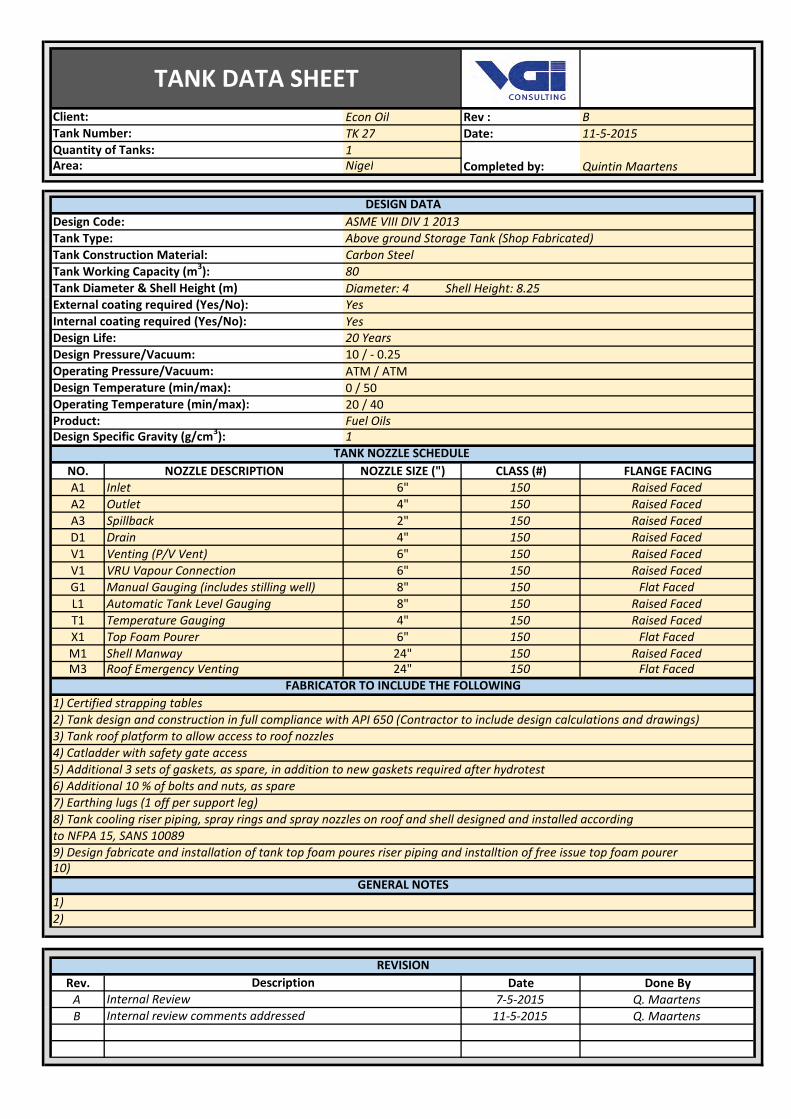
Econ Oil Rev : B
TK 27 Date: 11‐5‐2015
1Nigel
Diameter: 4 Shell Height: 8.25
Yes
ATM / ATM
0 / 50
20 / 40
NO. NOZZLE DESCRIPTION NOZZLE SIZE (") CLASS (#) FLANGE FACING
A1 Inlet 6" 150 Raised Faced
A2 Outlet 4" 150 Raised Faced
A3 Spillback 2" 150 Raised Faced
D1 Drain 4" 150 Raised Faced
V1 Venting (P/V Vent) 6" 150 Raised Faced
V1 VRU Vapour Connection 6" 150 Raised Faced
G1 Manual Gauging (includes stilling well) 8" 150 Flat Faced
L1 Automatic Tank Level Gauging 8" 150 Raised Faced
T1 Temperature Gauging 4" 150 Raised Faced
X1 Top Foam Pourer 6" 150 Flat Faced
M1 Shell Manway 24" 150 Raised FacedM3 Roof Emergency Venting 24" 150 Flat Faced
Rev. Date Done By
A 7‐5‐2015 Q. Maartens
B 11‐5‐2015 Q. Maartens
Quantity of Tanks:
Completed by: Quintin Maartens
2)
Description
10)
FABRICATOR TO INCLUDE THE FOLLOWING
9) Design fabricate and installation of tank top foam poures riser piping and installtion of free issue top foam pourer
GENERAL NOTES
1)
3) Tank roof platform to allow access to roof nozzles
4) Catladder with safety gate access
7) Earthing lugs (1 off per support leg)
to NFPA 15, SANS 10089
8) Tank cooling riser piping, spray rings and spray nozzles on roof and shell designed and installed according
TANK NOZZLE SCHEDULE
Internal Review
REVISION
Internal review comments addressed
1) Certified strapping tables
2) Tank design and construction in full compliance with API 650 (Contractor to include design calculations and drawings)
5) Additional 3 sets of gaskets, as spare, in addition to new gaskets required after hydrotest
6) Additional 10 % of bolts and nuts, as spare
Client:
Tank Number:
Area:
Design Specific Gravity (g/cm3): 1
Yes
Internal coating required (Yes/No):
Design Life:
Operating Pressure/Vacuum:
Design Temperature (min/max):
Operating Temperature (min/max):
20 Years
TANK DATA SHEET
Product: Fuel Oils
Design Code: ASME VIII DIV 1 2013
Tank Type: Above ground Storage Tank (Shop Fabricated)
Tank Working Capacity (m3): 80
DESIGN DATA
Design Pressure/Vacuum: 10 / ‐ 0.25
Tank Diameter & Shell Height (m)
Tank Construction Material: Carbon Steel
External coating required (Yes/No):

Econ Oil Rev : B
TK 28 Date: 11‐5‐2015
1Nigel
Diameter: 4 Shell Height: 8.25
Yes
ATM / ATM
0 / 50
20 / 40
NO. NOZZLE DESCRIPTION NOZZLE SIZE (") CLASS (#) FLANGE FACING
A1 Inlet 4" 150 Raised Faced
A2 Outlet 6" 150 Raised Faced
A3 Spillback 2" 150 Raised Faced
D1 Drain 4" 150 Raised Faced
V1 Venting 6" 150 Raised Faced
G1 Manual Gauging (includes stilling well) 8" 150 Flat Faced
L1 Automatic Tank Level Gauging 8" 150 Raised Faced
T1 Temperature Gauging 4" 150 Raised Faced
X1 Top Foam Pourer 6" 150 Flat Faced
M1 Shell Manway 24" 150 Raised FacedM3 Roof Emergency Venting 24" 150 Flat Faced
Rev. Date Done By
A 7‐5‐2015 Q. Maartens
B 11‐5‐2015 Q. Maartens
TANK DATA SHEET
Product: Fuel Oils
Design Code: ASME VIII DIV 1 2013
Tank Type: Above ground Storage Tank (Shop Fabricated)
Tank Working Capacity (m3): 80
DESIGN DATA
Design Pressure/Vacuum: 10 / ‐ 0.25
Tank Diameter & Shell Height (m)
Tank Construction Material: Carbon Steel
External coating required (Yes/No):
1) Certified strapping tables
2) Tank design and construction in full compliance with API 650 (Contractor to include design calculations and drawings)
5) Additional 3 sets of gaskets, as spare, in addition to new gaskets required after hydrotest
6) Additional 10 % of bolts and nuts, as spare
Client:
Tank Number:
Area:
Design Specific Gravity (g/cm3): 1
Yes
Internal coating required (Yes/No):
Design Life:
Operating Pressure/Vacuum:
Design Temperature (min/max):
Operating Temperature (min/max):
20 Years
Internal Review
REVISION
Internal review comments addressed
Quantity of Tanks:
Completed by: Quintin Maartens
2)
Description
10)
FABRICATOR TO INCLUDE THE FOLLOWING
9) Design fabricate and installation of tank top foam poures riser piping and installtion of free issue top foam pourer
GENERAL NOTES
1)
3) Tank roof platform to allow access to roof nozzles
4) Catladder with safety gate access
7) Earthing lugs (1 off per support leg)
to NFPA 15, SANS 10089
8) Tank cooling riser piping, spray rings and spray nozzles on roof and shell designed and installed according
TANK NOZZLE SCHEDULE