Embed Size (px)
Citation preview

EDAS USER MANUAL
April 2016

Contact Information Contact Name: Rich Laffin Phone: 780-454-2505 Email: [email protected]
Campbell Scientific Canada Corp. 14532 131 Avenue NW Edmonton, AB T5L4X4 General telephone number: 780-454-2505 Toll free number: 844-454-2505 General inquiry e-mail: [email protected]
Please note that any one of Campbell Scientific’s Measurement Consultants will be happy to assist you with any of your inquiries.

i
Table of Contents PDF viewers: These page numbers refer to the printed version of this document. Use the PDF reader bookmarks tab for links to specific sections.
1. Water Survey Canada EDAS Station Summary ....... 1
2. Equipment Overview .................................................. 2
2.1 EDAS Details ....................................................................................... 3 2.1.1 Enclosure ...................................................................................... 4 2.1.2 CR850-XT (EDAS) Datalogger .................................................... 6
2.1.2.1 Wiring Diagram .................................................................. 7 2.1.2.2 Using the Keypad Display .................................................. 8
2.1.3 Switched 12V Power................................................................... 10 2.1.4 Stevens SatComm GOES Transmitter ........................................ 10 2.1.5 BulletPlus Cellular Modem ......................................................... 12 2.1.6 Terminal Block ........................................................................... 13
2.2 Mounting Equipment and Accessories ............................................... 14
3. Installation ................................................................ 16
3.1 Installation Overview ......................................................................... 16 3.2 Antenna Installation ........................................................................... 17
3.2.1 Cellular 3dB Omni-Direction Antenna ....................................... 17 3.2.2 GPS 28 dBi Omni-Directional Antenna ...................................... 18 3.2.3 GOES Yagi 5.5dB Directional V2TH Antenna and Mount ........ 18
4. Download EasyLync to a PC ................................... 20
5. Setting up a Connection from EDAS to EasyLync 22
5.1 Direct (RS-232) Connection (Com Port) to EDAS ............................ 23 5.2 Wireless Connection Setup and Considerations ................................. 24
5.2.1 Wirelessly Connect to EDAS ...................................................... 24 5.3 Connect to EDAS using a Phone Line ............................................... 26
6. EasyLync Software .................................................. 26
6.1.1 EasyLync Menu Bar ................................................................... 27 6.1.2 Using SHEF Codes with EasyLync ............................................ 28 6.1.3 EasyLync Warning Icon ............................................................. 28
6.2 Dashboard .......................................................................................... 28 6.2.1 Dashboard: Connecting to EasyLync .......................................... 28 6.2.2 Dashboard: Connected to EasyLync ........................................... 31
6.3 Sensors ............................................................................................... 32 6.3.1 Sensors: Details Tab ................................................................... 32 6.3.2 Sensors: Alarms Tab ................................................................... 40
6.4 Storage ............................................................................................... 43 6.5 Communications ................................................................................ 44
6.5.1 Communcations: Wi-Fi ............................................................... 46 6.5.2 Communications: Cellular .......................................................... 46
6.5.2.1 Communications: Cellular: Settings ................................. 47
6.5.2.2 Communications: Cellular: Maintenance ........................ 48 6.5.3 Communications: GOES ............................................................ 49
6.5.3.1 Communications: GOES: SatComm Setup ..................... 52 6.5.3.2 Communications: GOES: Self-Times Setup .................... 53 6.5.3.3 Communications: GOES: Random Setup ........................ 55 6.5.3.4 Communications: GOES Comm Port Setup .................... 56 6.5.3.5 Communications: GOES: DCP Setup.............................. 58 6.5.3.6 Communications: GOES: Summary ................................ 59 6.5.3.7 Communications: GOES: Self-Timed Transmission ....... 60 6.5.3.8 Communications: GOES: Random Transmission ........... 63 Communications: GOES: Alignment .............................................. 64
6.6 Data & Calibration ............................................................................ 66 6.6.1 Data & Calibration: Table Monitor Tab ..................................... 66 6.6.2 Data & Calibration: Data Collection Tab ................................... 67 6.6.3 Data & Calibration: Live Reading and Calibration Tab ............. 70 6.6.4 Data & Calibration: Graph Tab .................................................. 72
6.7 Settings .............................................................................................. 74 6.7.1 Settings: Station Settings Tab .................................................... 74 6.7.2 Settings: SW1 and SW2 Tabs .................................................... 76
6.8 Diagnostics ........................................................................................ 77 6.8.1 Diagnostics: Status Table Tab .................................................... 77 6.8.2 Diagnostics: Terminal Emulator Tab ......................................... 78
6.9 Save & Send ...................................................................................... 79
7. Maintenance ............................................................. 81
7.1 Internal Lithium Battery .................................................................... 81 7.1.1 Field Battery Replacement and Maintenance ............................. 81
Appendix A. Full Enclosure Schematic ..................... 85
A.1 Full Enclosure ................................................................................... 85
Figures Figure 2-1 EDAS equipment overview ........................................................... 2 Figure 2-2 Side view enclosure schematic ...................................................... 4 Figure 2-3 Top view enclosure schematic ....................................................... 5 Figure 2-4 Bottom view of enclosure .............................................................. 5 Figure 2-5 CR850-XT Datalogger .................................................................. 6 Figure 2-6 CR850-XT wiring panel general layout ........................................ 7 Figure 2-7 Available CR850-XT sensor ports ................................................ 8 Figure 2-8 Stevens SatComm Transmitter front panel .................................. 11 Figure 2-9 Stevens SatComm Transmitter back panel .................................. 11 Figure 2-10 Bullet-LTE front panel .............................................................. 12 Figure 2-11 Bullet-LTE back panel .............................................................. 12 Figure 2-12 Terminal block .......................................................................... 14 Figure 2-13 GOES Yagi 5.5dB Directional V2TH Antenna side view with pole
mount ............................................................................................. 15 Figure 2-14 Cellular Modem Omni-Directional Antenna (C2083) ............... 15 Figure 2-15 GPS 28 dBi Omni-directional Antenna Mount (L30626) ......... 16 Figure 3-1 3dB Omni-Directional Antenna (C2083) .................................... 17 Figure 3-2 GPS 28 dBi Omni-Directional Antenna (L17992) with mount and
coaxial cable .................................................................................. 18 Figure 3-3 GOES V2TH 5.5dB Directional Antenna (V2TH antenna) mounting
information..................................................................................... 19
Figure 3-4 Satellite antenna side view with elevation mount ........................ 20 Figure 4-1 EasyLync Access ......................................................................... 20 Figure 4-2 EasyLync Access Portal ............................................................... 21 Figure 4-3 Download EasyLync Software button .......................................... 21 Figure 4-4 EasyLync Setup Wizard Install .................................................... 22 Figure 4-5 EasyLync Setup Wizard Complete .............................................. 22 Figure 5-1 USB to 9-pin male serial converter (L17394) .............................. 23 Figure 5-2 9-pin male to 9-pin female serial cable (L10873) ........................ 24 Figure 5-3 Windows network icon ................................................................ 25 Figure 5-4 Windows network menu .............................................................. 25 Figure 5-5 Windows network security key pop-up ........................................ 25 Figure 5-6 COM220 Phone Modem .............................................................. 26 Figure 6-1 EasyLync Toolbar ........................................................................ 26 Figure 6-2 File dropdown menu .................................................................... 27 Figure 6-3 Settings dropdown menu .............................................................. 27 Figure 6-4 Help dropdown menu ................................................................... 28 Figure 6-5 Yellow warning icon .................................................................... 28 Figure 6-6 Unconnected Dashboard .............................................................. 29 Figure 6-7 Dashboard: IP Connection Configuration .................................... 30 Figure 6-8 Phone Line Configuration ............................................................ 30 Figure 6-9 Serial/Direct Connection Configuration ....................................... 31 Figure 6-10 Connected Dashboard ................................................................ 32 Figure 6-11 Sensors: Details .......................................................................... 33 Figure 6-12 Sensors: Details: Basic Settings ................................................. 33 Figure 6-13 Sensors: Details: Measurements Schedule ................................. 35 Figure 6-14 Sensors: Details: Equation ......................................................... 35 Figure 6-15 Measurements: Details: Power Management ............................. 36 Figure 6-16 Sensors: Details: Analog Bull-Bridge Settings .......................... 36 Figure 6-17 Sensors: Details: Analog-VoltSE Settings ................................. 37 Figure 6-18 Sensors: Details: Processing Settings ......................................... 37 Figure 6-19 Sensors: Details: Pulse Count/Rate Settings .............................. 38 Figure 6-20 SDI-12 Settings .......................................................................... 38 Figure 6-21 Sensors: Alarms Tab .................................................................. 40 Figure 6-22 Sensors: Alarms: High Threshold Alarm ................................... 41 Figure 6-23 Sensors: Alarms: Low Threshold Alarms .................................. 41 Figure 6-24 Sensors: Alarms: Rate of Change Alarm ................................... 42 Figure 6-25 Sensors: Alarms Tab: Alarm Action Configuration ................... 42 Figure 6-26 Storage ....................................................................................... 43 Figure 6-27 Storage: Data Table – Details..................................................... 44 Figure 6-28 Storage: Details: Available Measurements ................................ 44 Figure 6-29 Communications: Basic Configuration Tab ............................... 45 Figure 6-30 Click to Launch Modem Configuration button .......................... 46 Figure 6-31 Summary Tab ............................................................................. 46 Figure 6-32 Cellular Settings Tab .................................................................. 47 Figure 6-33 Cellular Maintenance Tab .......................................................... 48 Figure 6-34 Connect and Launch SatComm Configuration button ............... 50 Figure 6-35 Stevens SatComm Driver Software Installation window ........... 50 Figure 6-36 Stevens SatComm Disconnected ................................................ 51 Figure 6-37 Stevens SatComm Setup Tab ..................................................... 52 Figure 6-38 Stevens SatComm Self-Timed Setup Tab .................................... 53 Figure 6-39 Random Setup Tab ..................................................................... 55 Figure 6-40 Comm Port Setup Tab ................................................................ 56 Figure 6-41 DCP Setup Tab ........................................................................... 58 Figure 6-42 Summary Tab ............................................................................. 59 Figure 6-43 Self-Timed Transmission ........................................................... 61 Figure 6-46 Fields in Data Table to Include .................................................. 62
Figure 6-47 SHEF Code ................................................................................ 62 Figure 6-48 Self-Timed Transmission Added SHEF Blocks ........................ 63 Figure 6-49 Random Transmissions ............................................................. 64 Figure 6-51 Alignment .................................................................................. 64 Figure 6-52 Alignment: Magnetic Variance ................................................. 65 Figure 6-53 Alignment: Results .................................................................... 65 Figure 6-54 Data & Calibration: Table Monitor ........................................... 66 Figure 6-55 Data & Calibration: Data Collection Tab .................................. 67 Figure 6-56 Starting Record Information ...................................................... 69 Figure 6-57 Data from a Selected Date and Time ......................................... 69 Figure 6-58 Starting Record Information ...................................................... 69 Figure 6-59 Data Collection in progress window ......................................... 69 Figure 6-60 Data & Calibration: Live Reading and Calibration ................... 70 Figure 6-61 Live Reading ............................................................................. 71 Figure 6-62 Calibration Settings ................................................................... 71 Figure 6-63 Data & Calibration: Graph ........................................................ 72 Figure 6-64 Date Settings ............................................................................. 73 Figure 6-65 End Range Options .................................................................... 73 Figure 6-66 Settings: Station Settings ........................................................... 74 Figure 6-67 Station Settings: Station Clock .................................................. 75 Figure 6-68: Station Settings: System Cutoffs and Settings ......................... 75 Figure 6-69 Settings: SW1 Tab ..................................................................... 76 Figure 6-70 Diagnostics: Status Table .......................................................... 77 Figure 6-71 Diagnostics: Terminal Emulator ................................................ 78 Figure 6-72 Save & Send .............................................................................. 79 Figure 6-73 Save & Send: Confirm Send Pop-up ......................................... 80 Figure 7-1 Lithium battery replacement ........................................................ 84
Tables Table 2-1 EDAS Equipment Overview ........................................................... 2 Table 2-2 Botton View of Enclosure............................................................... 6 Table 2-3 Special Keypad-Display Key Functions ......................................... 8 Table 2-4 Datalogger Keypad Main Display .................................................. 9 Table 2-5 Stevens SatComm GOES Transmitter Connections ..................... 11 Table 2-6 Pre-configured Bullet-LTE Connections inside the EDAS Enclosure
....................................................................................................... 13 Table 2-7 EDAS Terminal Block Wiring ..................................................... 13 Table 2-8 Mounting Equipment and Accessories ......................................... 14 Table 6-1 File Dropdown Menu .................................................................... 27 Table 6-2 Connection Type ........................................................................... 29 Table 6-3 Phone Line Configuration ............................................................. 30 Table 6-4 Serial/Direct Connection Configuration ....................................... 31 Table 6-5 Station Name ................................................................................ 32 Table 6-6 Basic Settings ............................................................................... 34 Table 6-7 Measurement Schedule ................................................................. 35 Table 6-8 Equation ........................................................................................ 36 Table 6-9 Power Management ...................................................................... 36 Table 6-10 Analog Half Bridge and Analog Full Bridge Settings ................ 37 Table 6-11 Processing Settings ..................................................................... 38 Table 6-12 Pulse Count/Rate Settings ........................................................... 38 Table 6-13 SDI-12 Settings ........................................................................... 39 Table 6-14 SDI-12 Multiple Output Parent Settings ..................................... 39 Table 6-15 SDI-12 Multiple Output Child Settings ...................................... 40 Table 6-14 High Threshold Alarm ................................................................ 41
Table 6-15 Low Threshold Alarm ................................................................. 41 Table 6-16 Rate of Change Alarm ................................................................. 42 Table 6-17 Alarm Action Configuration ........................................................ 42 Table 6-20 Available Measurements ............................................................. 44 Table 6-19 Firmware Updates ....................................................................... 49 Table 6-20 Backup Configurations ................................................................ 49 Table 6-21 Stevens SatComm Disconnected ................................................. 51 Table 6-22 Stevens SatComm Setup .............................................................. 52 Table 6-23. Stevens SatComm Self-Timed Setup......................................... 54 Table 6-24. Stevens SatComm Random Setup ............................................. 55 Table 6-25. USB Virtual Comm Port ............................................................ 57 Table 6-26. External Touch Screen ............................................................... 57 Table 6-27 External Datalogger Interface ...................................................... 58 Table 6-28. Summary .................................................................................... 60 Table 6-29. Self-Timed Transmission: Configure GOES Self-Timed
Transmission ................................................................................... 61 Table 6-31. Fields in Data Table to Include................................................... 62 Table 6-32. SHEF Code ................................................................................. 63 Table 6-33. Self-Timed Transmission Added SHEF Blocks ......................... 63 Table 6-34. Alignment: Magnetic Varience .................................................. 65 Table 6-35 Table Monitor: Real Time Monitoring ........................................ 67 Table 6-36 Data Collection ............................................................................ 68 Table 6-37 Starting Record Information ........................................................ 69 Table 6-38 Living Reading ............................................................................ 71 Table 6-39 Calibration Settings ..................................................................... 72 Table 6-40 Measurements/Tables to Graph ................................................... 73 Table 6-41 End Range Options ...................................................................... 73 Table 6-42 Station Clock ............................................................................... 75 Table 6-43 System Cutoffs and Settings ........................................................ 76 Table 6-44 SW1 Tab ...................................................................................... 77 Table 6-45 Status Table ................................................................................. 78 Table 6-46 Terminal Emulator ...................................................................... 79 Table 7-1 Equipment Maintenance Schedule ................................................ 81


1
Water Survey Canada Environmental Data Acquisition System (EDAS) 1. Water Survey Canada EDAS Station Summary
The Environmental Data Acquisition System (EDAS) has been designed to meet the operational monitoring needs of Water Survey Canada’s Level I and Level II EDASs. This measurement system is comprised of a Campbell Scientific CR850-XT measurement and control datalogger, and is equipped with various telemetry options including:
Direct connection Stevens Water GOES Modem Microhard BulletPlus Cellular Modem
The system is capable of measuring an event using a pulse channel, analog sensors using its voltage channels, SDI-12 sensors using its digital channels, and can turn sensors on or off using switched power terminals.
Each EDAS comes pre-configured by Campbell Scientific Canada (CSC) for specifc applications. Through EasyLync (CSC’s Windows based user interface), end users can configure the EDAS for their specifc needs.
This manual provides detailed information about the equipment used for the EDAS stations including general descriptions, information, maintenance schedules, basics on direct and wireless connections, station setup, troubleshooting tips, and installation procedures.
2
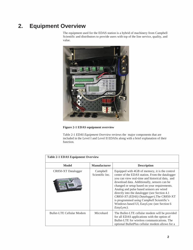
2. Equipment Overview The equipment used for the EDAS station is a hybrid of machinery from Campbell Scientific and distributors to provide users with top of the line service, quality, and value.
Figure 2-1 EDAS equipment overview
Table 2-1 EDAS Equipment Overview reviews the major components that are included in the Level I and Level II EDASs along with a brief explanation of their function.
Table 2-1 EDAS Equipment Overview
Model Manufacturer Description
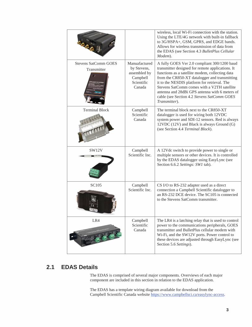
CR850-XT Datalogger
Campbell Scientific Inc.
Equipped with 4GB of memory, it is the control center of the EDAS station. From the datalogger you can view real-time and historical data, and download data. Additionally, sensors can be changed or setup based on your requirements. Analog and pulse based sensors are wired directly into the datalogger (see Section 4.1 CR850-XT (EDAS) Datalogger).The CR850-XT is programmed using Campbell Scientific’s Windows based UI, EasyLync (see Section 6 EasyLync).
Bullet-LTE Cellular Modem Microhard The Bullet-LTE cellular modem will be provided for all EDAS applications with the option of Bullet-LTE for wireless communications. The optional BulletPlus cellular modem allows for a
3
wireless, local Wi-Fi connection with the station. Using the LTE/4G network with built-in fallback to 3G/HSPA+, GSM, GPRS, and EDGE bands. Allows for wireless transmission of data from the EDAS (see Section 4.3 BulletPlus Cellular Modem).
Stevens SatComm GOES Transmitter
Manuafactured by Stevens,
assembled by Campbell Scientific Canada
A fully GOES Ver 2.0 compliant 300/1200 baud transmitter designed for remote applications. It functions as a satellite modem, collecting data from the CR850-XT datalogger and transmitting it to the NESDIS platform for retrieval. The Stevens SatComm comes with a V2TH satellite antenna and 28dBi GPS antenna with 6 meters of cable (see Section 4.2 Stevens SatComm GOES Transmitter).
Terminal Block
Campbell Scientific Canada
The terminal block next to the CR850-XT datalogger is used for wiring both 12VDC system power and SDI-12 sensors. Red is always 12VDC (12V) and Black is always Ground (G) (see Section 4.4 Terminal Block).
SW12V
Campbell Scientific Inc.
A 12Vdc switch to provide power to single or multiple sensors or other devices. It is controlled by the EDAS datalogger using EasyLync (see Section 6.6.2 Settings: SW1 tab).
SC105
Campbell Scientific Inc.
CS I/O to RS-232 adapter used as a direct connection a Campbell Scientific datalogger to an RS-232 DCE device. The SC105 is connected to the Stevens SatComm transmitter.
LR4
Campbell Scientific Canada
The LR4 is a latching relay that is used to control power to the communications peripherals, GOES transmitter and BulletPlus cellular modem with Wi-Fi, and the SW12V ports. Power control to these devices are adjusted through EasyLync (see Section 5.6 Settings).
2.1 EDAS Details The EDAS is comprised of several major components. Overviews of each major component are included in this section in relation to the EDAS application.
The EDAS has a template wiring diagram available for download from the Campbell Scientific Canada website https://www.campbellsci.ca/easylync-access.
4
At any time when utilising this system, make certain you are referencing the correct wiring information to ensure accurate data and test power and sensor functionality prior to leaving the site.
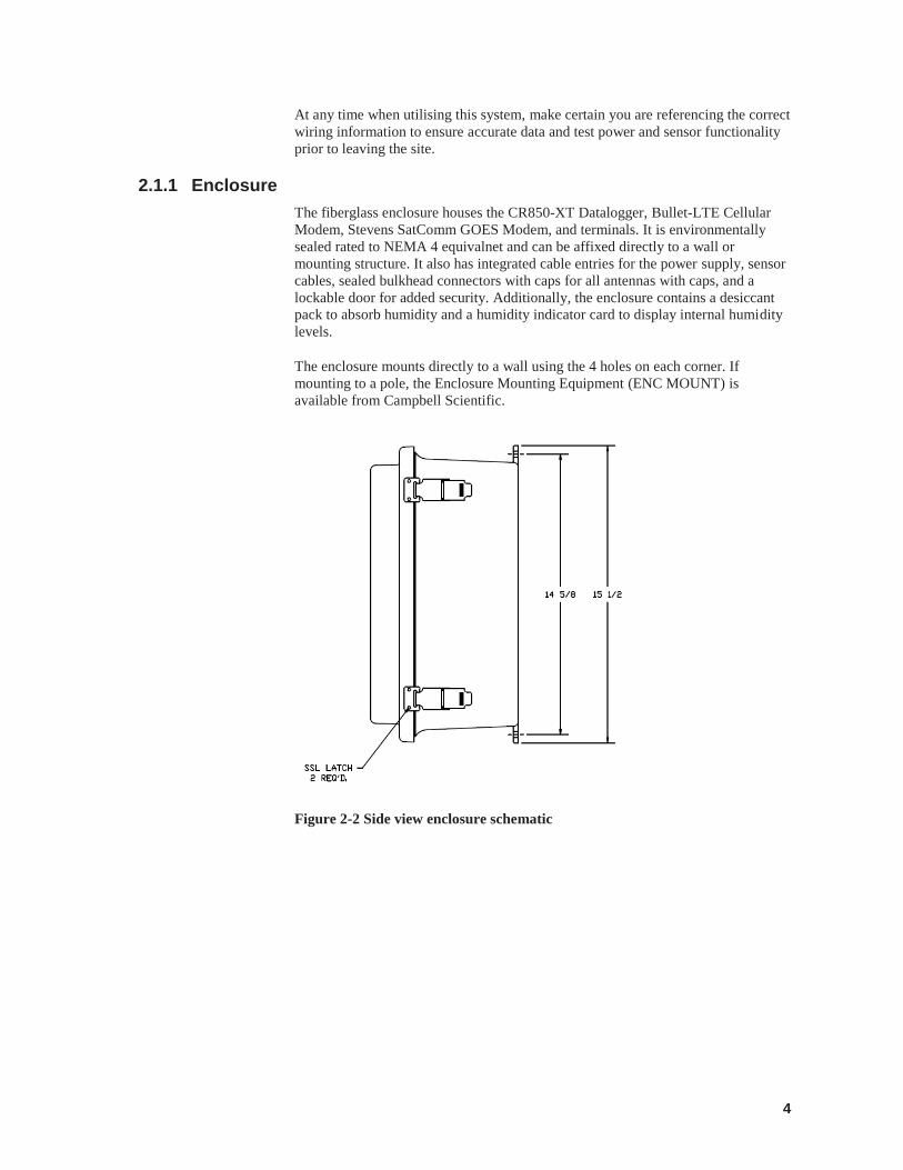
2.1.1 Enclosure The fiberglass enclosure houses the CR850-XT Datalogger, Bullet-LTE Cellular Modem, Stevens SatComm GOES Modem, and terminals. It is environmentally sealed rated to NEMA 4 equivalnet and can be affixed directly to a wall or mounting structure. It also has integrated cable entries for the power supply, sensor cables, sealed bulkhead connectors with caps for all antennas with caps, and a lockable door for added security. Additionally, the enclosure contains a desiccant pack to absorb humidity and a humidity indicator card to display internal humidity levels.
The enclosure mounts directly to a wall using the 4 holes on each corner. If mounting to a pole, the Enclosure Mounting Equipment (ENC MOUNT) is available from Campbell Scientific.
Figure 2-2 Side view enclosure schematic
5
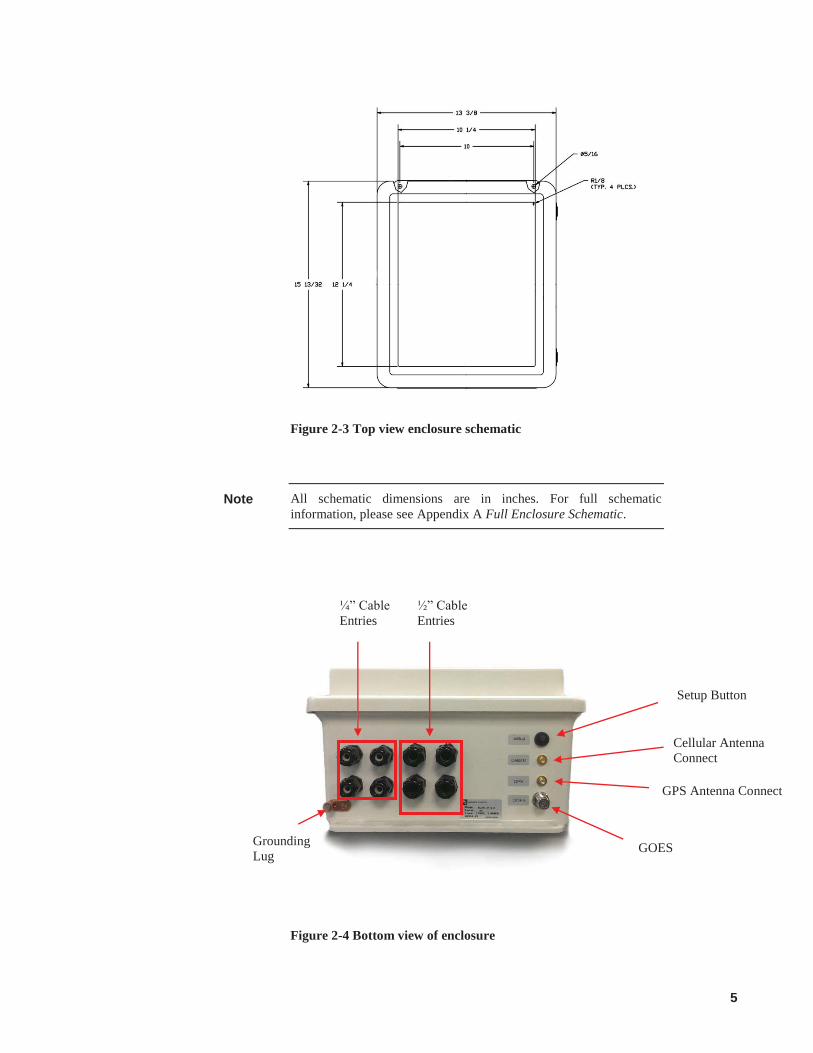
Figure 2-3 Top view enclosure schematic
All schematic dimensions are in inches. For full schematic information, please see Appendix A Full Enclosure Schematic.
Figure 2-4 Bottom view of enclosure
Note
GOES
GPS Antenna Connect
Setup Button
¼” Cable Entries
½” Cable Entries
Grounding Lug
Cellular Antenna Connect
6
The EDAS includes a Setup button. It is used to turn on the EDAS and enable Wi-Fi communications. Once the button is pushed, the EDAS will turn on within 10 seconds. It may take up to several minutes for the network to be visible on the PC.
Table 2-2 Botton View of Enclosure
Element Description
Setup Button. Used to power on EDAS and Wi-Fi for wireless connection through Stevens SatComm modem.
Cellular Antenna. Used for SatComm cellular communications.
GPS Antenna. Used for GPS communications.
GOES Antenna. Used for GOES communcations.
¼” Cable Entries ¼” dimameter cable entry. Plugs are used to cover the entries when not in use. Enteries are typically used for a sensor cable.
½” Cable Entries ½” dimameter cable entry. Plugs are used to cover the entries when not in use. Entries are typically used for sensor cables.
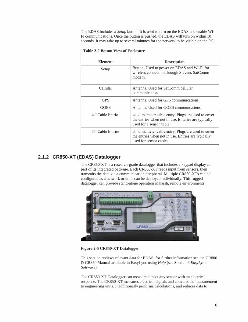
2.1.2 CR850-XT (EDAS) Datalogger The CR850-XT is a research-grade datalogger that includes a keypad display as part of its integrated package. Each CR850-XT reads input from sensors, then transmits the data via a communication peripheral. Multiple CR850-XTs can be configured as a network or units can be deployed individually. This rugged datalogger can provide stand-alone operation in harsh, remote environments.
Figure 2-5 CR850-XT Datalogger
This section reviews relevant data for EDAS, for further information see the CR800 & CR850 Manual available in EasyLync using Help (see Section 6 EasyLync Software).
The CR850-XT Datalogger can measure almost any sensor with an electrical response. The CR850-XT measures electrical signals and converts the measurement to engineering units. It additionally performs calculations, and reduces data to

7
statistical values. Not every measurement needs to be stored. The CR850-XT will store data in memory awaiting transfer to the PC via external storage devices or telecommunications. Figure 2-6 CR850-XT wiring panel general layout describes an overview of the functionality of the datalogger. The datalogger is programmed using EasyLync software, see Section 6 EasyLync Software.
2.1.2.1 Wiring Diagram This section reviews relevant wiring information for EDAS applications, for further information see the CR800 Manual available in EasyLync using Help (see Section 6 EasyLync Software).
Figure 2-6 CR850-XT wiring panel general layout
8
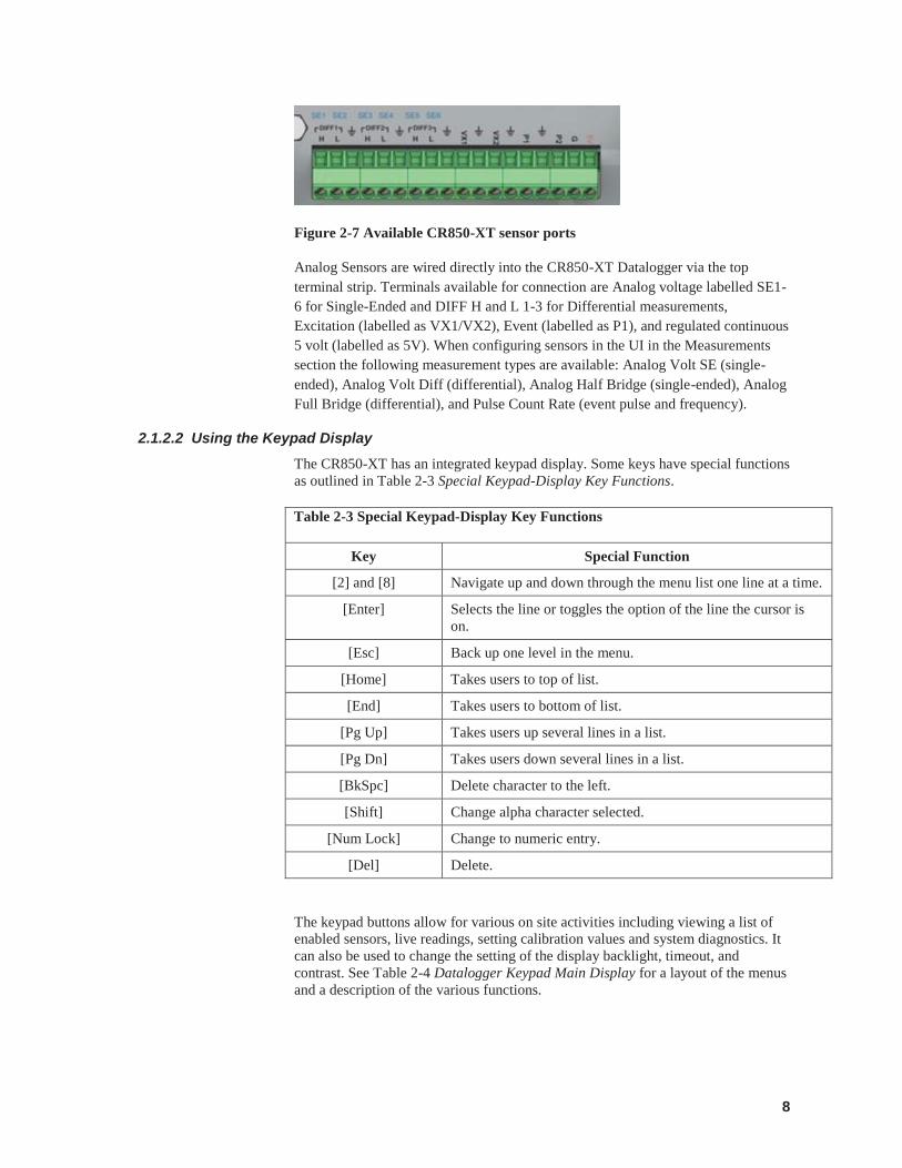
Figure 2-7 Available CR850-XT sensor ports
Analog Sensors are wired directly into the CR850-XT Datalogger via the top terminal strip. Terminals available for connection are Analog voltage labelled SE1-6 for Single-Ended and DIFF H and L 1-3 for Differential measurements, Excitation (labelled as VX1/VX2), Event (labelled as P1), and regulated continuous 5 volt (labelled as 5V). When configuring sensors in the UI in the Measurements section the following measurement types are available: Analog Volt SE (single-ended), Analog Volt Diff (differential), Analog Half Bridge (single-ended), Analog Full Bridge (differential), and Pulse Count Rate (event pulse and frequency).
2.1.2.2 Using the Keypad Display The CR850-XT has an integrated keypad display. Some keys have special functions as outlined in Table 2-3 Special Keypad-Display Key Functions.
Table 2-3 Special Keypad-Display Key Functions
Key Special Function
[2] and [8] Navigate up and down through the menu list one line at a time.
[Enter] Selects the line or toggles the option of the line the cursor is on.
[Esc] Back up one level in the menu.
[Home] Takes users to top of list.
[End] Takes users to bottom of list.
[Pg Up] Takes users up several lines in a list.
[Pg Dn] Takes users down several lines in a list.
[BkSpc] Delete character to the left.
[Shift] Change alpha character selected.
[Num Lock] Change to numeric entry.
[Del] Delete.
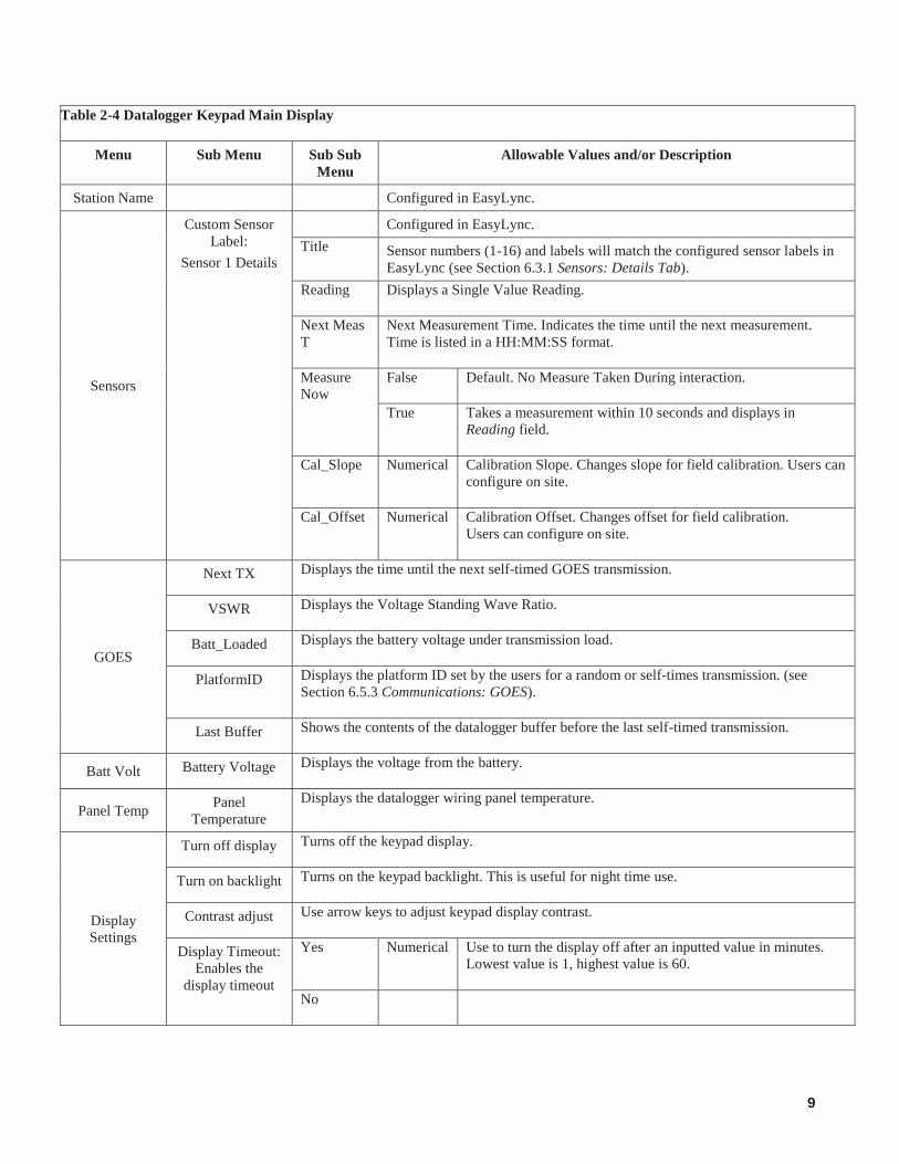
The keypad buttons allow for various on site activities including viewing a list of enabled sensors, live readings, setting calibration values and system diagnostics. It can also be used to change the setting of the display backlight, timeout, and contrast. See Table 2-4 Datalogger Keypad Main Display for a layout of the menus and a description of the various functions.
9
Table 2-4 Datalogger Keypad Main Display
Menu Sub Menu Sub Sub Menu
Allowable Values and/or Description
Station Name Configured in EasyLync.
Sensors
Custom Sensor Label:
Sensor 1 Details
Configured in EasyLync. Title Sensor numbers (1-16) and labels will match the configured sensor labels in
EasyLync (see Section 6.3.1 Sensors: Details Tab). Reading Displays a Single Value Reading.
Next Meas T
Next Measurement Time. Indicates the time until the next measurement. Time is listed in a HH:MM:SS format.
Measure Now
False Default. No Measure Taken During interaction.
True Takes a measurement within 10 seconds and displays in Reading field.
Cal_Slope Numerical Calibration Slope. Changes slope for field calibration. Users can configure on site.
Cal_Offset Numerical Calibration Offset. Changes offset for field calibration. Users can configure on site.
GOES
Next TX Displays the time until the next self-timed GOES transmission.
VSWR Displays the Voltage Standing Wave Ratio.
Batt_Loaded Displays the battery voltage under transmission load.
PlatformID Displays the platform ID set by the users for a random or self-times transmission. (see Section 6.5.3 Communications: GOES).
Last Buffer Shows the contents of the datalogger buffer before the last self-timed transmission.
Batt Volt Battery Voltage Displays the voltage from the battery.
Panel Temp Panel Temperature
Displays the datalogger wiring panel temperature.
Display Settings
Turn off display Turns off the keypad display.
Turn on backlight Turns on the keypad backlight. This is useful for night time use.
Contrast adjust Use arrow keys to adjust keypad display contrast.
Display Timeout: Enables the
display timeout
Yes Numerical Use to turn the display off after an inputted value in minutes. Lowest value is 1, highest value is 60.
No
10
2.1.3 Switched 12V Power The CR850-XT datalogger has two switched ports that provide 12VDC. The first is found directly on the CR850-XT wiring panel (see Figure 2-6 CR850-XT wiring panel general layout), which provides up to 900 mA of current at 25°C. The second is found external to the datalogger via the SW12V (see Table 2-1 EDAS Equipment Overview) and can provide up to 1.8 Amps at 25°C.
2.1.4 Stevens SatComm GOES Transmitter The SatComm GOES Satellite Modem, pre-configured in the enclosure, is connected via RS-232 ports C3 and C4 and via the SC105 9-pin peripheral connected to the CR850-XT (EDAS) datalogger. It is wired into the EDAS power terminal block at the factory.
This section reviews relevant data for EDAS, for further information see the Stevens SatComm Manual.
After intial power up of the EDAS, the Stevens SatComm warm-up begins. All the LED lights will illuminate on the top of the unit for 15 seconds while the Stevens SatComm goes through its built-in self-test (BIST) routine, after which they all go out except for the power (PWR) and GPS LEDs.
The unit will wait for the GPS receiver to give a time and date fix. After an initial GPS lock, if a valid GPS time and date fix is not obtained before the transmission time, the transmission will continue. If a GPS update has not been obtained for 24 hours, self-timed transmissions will be inhibited.
The Stevens SatComm has multiple operating modes. When the Stevens SatComm unit is in Online Mode, it is in a low power state called: Low Power Standby Mode. In this state, all the LEDs are out and the unit is consuming the minimal amount of power.
By pressing the Switch to Online Mode button in the Settings of EasyLync (see Section 6.7 Settings) the unit is put Online. When the unit is Online, the LEDs come on during a Self-Timed or Random transmission sequence. The LEDs also come on when the transmitter is in Off Line (Configuration) mode.

11
Table 2-5 Stevens SatComm GOES Transmitter Connections
Wire Color Function Connection
Black Power Ground System Ground
Red Input Power System Power Source (9-30VDC) via LR4 Relay 1.
Blue RS-232 Output CR850-XT – CS I/O (via SC105 and SC12) Stevens SatComm – External Logger DB9.
White RS-232 Input CR850-XT – C3 (RS-232 TX) Stevens SatComm – External Logger DB9
Green RS-232 Ground CR850-XT – G Stevens SatComm – External Logger DB9
Data CR850-XT – CS I/O (via SC105 and SC12) Stevens SatComm – Display Port DB9.
PC Connection USB
Black GPS Antenna GPS Ant.
Black GOES Antenna RF Output
Figure 2-8 Stevens SatComm Transmitter front panel
Figure 2-9 Stevens SatComm Transmitter back panel

12
2.1.5 BulletPlus Cellular Modem The BulletPlus Cellular Modem is pre-configured in the enclosure to connect to the datalogger via the 9-pin RS-232 port on the CR850-XT datalogger. The modem is powered by default on the datalogger switched 12V port with optional full-time 12V power (a change in wiring is required).
Some systems may have the BulletPlus as Wi-Fi is an option on each EDAS.
This section reviews relevant data for EDAS, for further information see the BulletPlus Operating Manual.
With the datalogger’s default power wiring, the BulletPlus remains in an Off state unless configured to turn on using EasyLync’s Communications, see Section 6.5.2 Communications: Cellular. This can also be achieved by pressing the Setup Button on the EDAS. Once the Setup button is pressed, the modem will turn on within 10 seconds and the modem will initiate its boot sequence. This can take up to several minutes. After this time, the EDAS Wi-Fi network is visible as Level I_II EDAS SNX, where X is the box serial number, and a wireless connection can be made, but by default the modem will only remain powered for 15 min, unless the external button is pressed again or the EDAS is configured to remain on for a longer period of time. Connecting to EDAS via Wi-Fi is convered in Section 5.2.1 Wirelessly Connect to EDAS.
Figure 2-10 Bullet-LTE front panel
Figure 2-11 Bullet-LTE back panel
Note
13
Table 2-6 Pre-configured Bullet-LTE Connections inside the EDAS Enclosure
Wire Color Function Connection
Black Power Ground System Ground (CR850)
Red Input Power Power Source (9-30VDC) (LR4)
Blue None Not used
White None Not used
Connect CR850-XT Datalogger to Bullet-LTE
Com 2 on the datalogger
Red Rx
Brown Tx
Yellow Ground
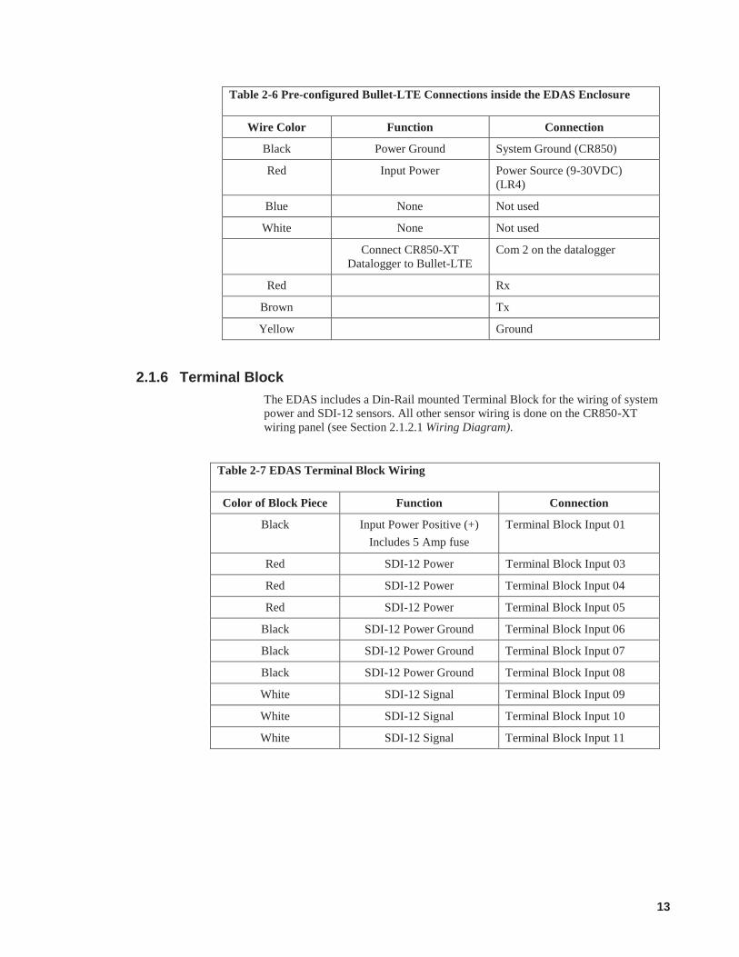
2.1.6 Terminal Block The EDAS includes a Din-Rail mounted Terminal Block for the wiring of system power and SDI-12 sensors. All other sensor wiring is done on the CR850-XT wiring panel (see Section 2.1.2.1 Wiring Diagram).
Table 2-7 EDAS Terminal Block Wiring
Color of Block Piece Function Connection
Black Input Power Positive (+) Includes 5 Amp fuse
Terminal Block Input 01
Red SDI-12 Power Terminal Block Input 03
Red SDI-12 Power Terminal Block Input 04
Red SDI-12 Power Terminal Block Input 05
Black SDI-12 Power Ground Terminal Block Input 06
Black SDI-12 Power Ground Terminal Block Input 07
Black SDI-12 Power Ground Terminal Block Input 08
White SDI-12 Signal Terminal Block Input 09
White SDI-12 Signal Terminal Block Input 10
White SDI-12 Signal Terminal Block Input 11
14
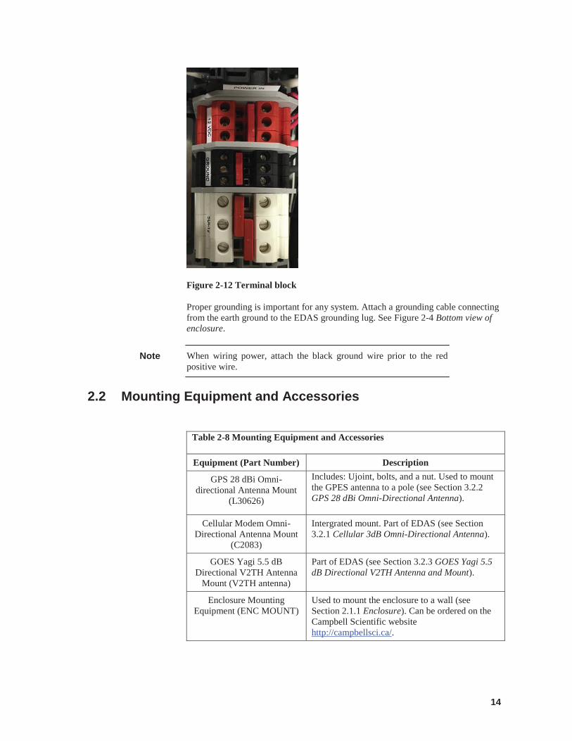
Figure 2-12 Terminal block
Proper grounding is important for any system. Attach a grounding cable connecting from the earth ground to the EDAS grounding lug. See Figure 2-4 Bottom view of enclosure.
When wiring power, attach the black ground wire prior to the red positive wire.
2.2 Mounting Equipment and Accessories
Table 2-8 Mounting Equipment and Accessories
Equipment (Part Number) Description
GPS 28 dBi Omni-directional Antenna Mount
(L30626)
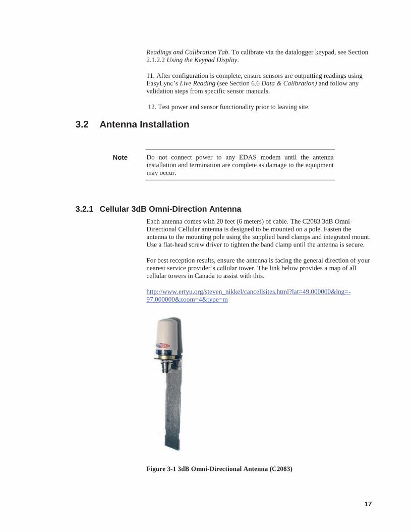
Includes: Ujoint, bolts, and a nut. Used to mount the GPES antenna to a pole (see Section 3.2.2 GPS 28 dBi Omni-Directional Antenna).
Cellular Modem Omni-Directional Antenna Mount
(C2083)
Intergrated mount. Part of EDAS (see Section 3.2.1 Cellular 3dB Omni-Directional Antenna).
GOES Yagi 5.5 dB Directional V2TH Antenna
Mount (V2TH antenna)
Part of EDAS (see Section 3.2.3 GOES Yagi 5.5 dB Directional V2TH Antenna and Mount).
Enclosure Mounting Equipment (ENC MOUNT)
Used to mount the enclosure to a wall (see Section 2.1.1 Enclosure). Can be ordered on the Campbell Scientific website http://campbellsci.ca/.
Note
15
The EDAS enclosure mounts directly to a wall using the 4 holes on each corner. If mounting to a pole, the Enclosure Mounting Equipment is available from Campbell Scientific.
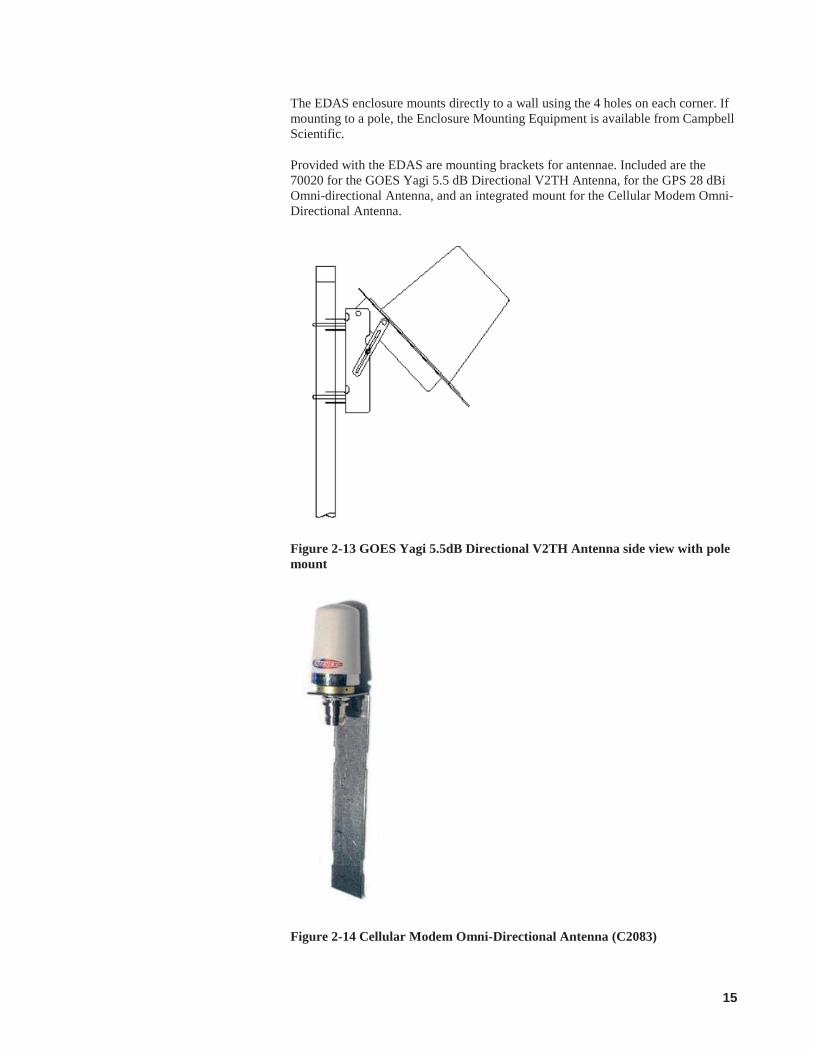
Provided with the EDAS are mounting brackets for antennae. Included are the 70020 for the GOES Yagi 5.5 dB Directional V2TH Antenna, for the GPS 28 dBi Omni-directional Antenna, and an integrated mount for the Cellular Modem Omni-Directional Antenna.
Figure 2-13 GOES Yagi 5.5dB Directional V2TH Antenna side view with pole mount
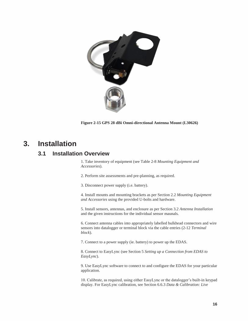
Figure 2-14 Cellular Modem Omni-Directional Antenna (C2083)
16
Figure 2-15 GPS 28 dBi Omni-directional Antenna Mount (L30626)
3. Installation 3.1 Installation Overview
1. Take inventory of equipment (see Table 2-8 Mounting Equipment and Accessories).
2. Perform site assessments and pre-planning, as required.
3. Disconnect power supply (i.e. battery).
4. Install mounts and mounting brackets as per Section 2.2 Mounting Equipment and Accessories using the provided U-bolts and hardware.
5. Install sensors, antennas, and enclosure as per Section 3.2 Antenna Installation and the given instructions for the individual sensor maunals.
6. Connect antenna cables into appropriately labelled bulkhead connectors and wire sensors into datalogger or terminal block via the cable entries (2-12 Terminal block).
7. Connect to a power supply (ie. battery) to power up the EDAS.
8. Connect to EasyLync (see Section 5 Setting up a Connection from EDAS to EasyLync).
9. Use EasyLync software to connect to and configure the EDAS for your particular application.
10. Calibrate, as required, using either EasyLync or the datalogger’s built-in keypad display. For EasyLync calibration, see Section 6.6.3 Data & Calibration: Live
17
Readings and Calibration Tab. To calibrate via the datalogger keypad, see Section 2.1.2.2 Using the Keypad Display.
11. After configuration is complete, ensure sensors are outputting readings using EasyLync’s Live Reading (see Section 6.6 Data & Calibration) and follow any validation steps from specific sensor manuals.
12. Test power and sensor functionality prior to leaving site.
3.2 Antenna Installation
Do not connect power to any EDAS modem until the antenna installation and termination are complete as damage to the equipment may occur.
3.2.1 Cellular 3dB Omni-Direction Antenna Each antenna comes with 20 feet (6 meters) of cable. The C2083 3dB Omni-Directional Cellular antenna is designed to be mounted on a pole. Fasten the antenna to the mounting pole using the supplied band clamps and integrated mount. Use a flat-head screw driver to tighten the band clamp until the antenna is secure.
For best reception results, ensure the antenna is facing the general direction of your nearest service provider’s cellular tower. The link below provides a map of all cellular towers in Canada to assist with this.
http://www.ertyu.org/steven_nikkel/cancellsites.html?lat=49.000000&lng=-97.000000&zoom=4&type=m
Figure 3-1 3dB Omni-Directional Antenna (C2083)
Note
18
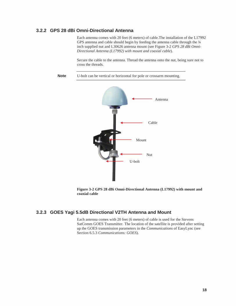
3.2.2 GPS 28 dBi Omni-Directional Antenna Each antenna comes with 20 feet (6 meters) of cable.The installation of the L17992 GPS antenna and cable should begin by feeding the antenna cable through the ¾ inch supplied nut and L30626 antenna mount (see Figure 3-2 GPS 28 dBi Omni-Directional Antenna (L17992) with mount and coaxial cable).
Secure the cable to the antenna. Thread the antenna onto the nut, being sure not to cross the threads.
U-bolt can be vertical or horizontal for pole or crossarm mounting.
Figure 3-2 GPS 28 dBi Omni-Directional Antenna (L17992) with mount and coaxial cable
3.2.3 GOES Yagi 5.5dB Directional V2TH Antenna and Mount Each antenna comes with 20 feet (6 meters) of cable is used for the Stevens SatComm GOES Transmitter. The location of the satellite is provided after setting up the GOES transmission parameters in the Communications of EasyLync (see Section 6.5.3 Communications: GOES).
Note
Mount
Cable
Nut
Antenna
U-bolt
19
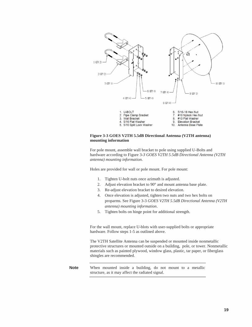
Figure 3-3 GOES V2TH 5.5dB Directional Antenna (V2TH antenna) mounting information
For pole mount, assemble wall bracket to pole using supplied U-Bolts and hardware according to Figure 3-3 GOES V2TH 5.5dB Directional Antenna (V2TH antenna) mounting information.
Holes are provided for wall or pole mount. For pole mount:
1. Tighten U-bolt nuts once azimuth is adjusted. 2. Adjust elevation bracket to 90° and mount antenna base plate. 3. Re-adjust elevation bracket to desired elevation. 4. Once elevation is adjusted, tighten two nuts and two hex bolts on
proparms. See Figure 3-3 GOES V2TH 5.5dB Directional Antenna (V2TH antenna) mounting information.
5. Tighten bolts on hinge point for additional strength.
For the wall mount, replace U-blots with user-supplied bolts or appropriate hardware. Follow steps 1-5 as outlined above.
The V2TH Satellite Antenna can be suspended or mounted inside nonmetallic protective structures or mounted outside on a building, pole, or tower. Nonmetallic materials such as painted plywood, window glass, plastic, tar paper, or fiberglass shingles are recommended.
When mounted inside a building, do not mount to a metallic structure, as it may affect the radiated signal.
Note
20
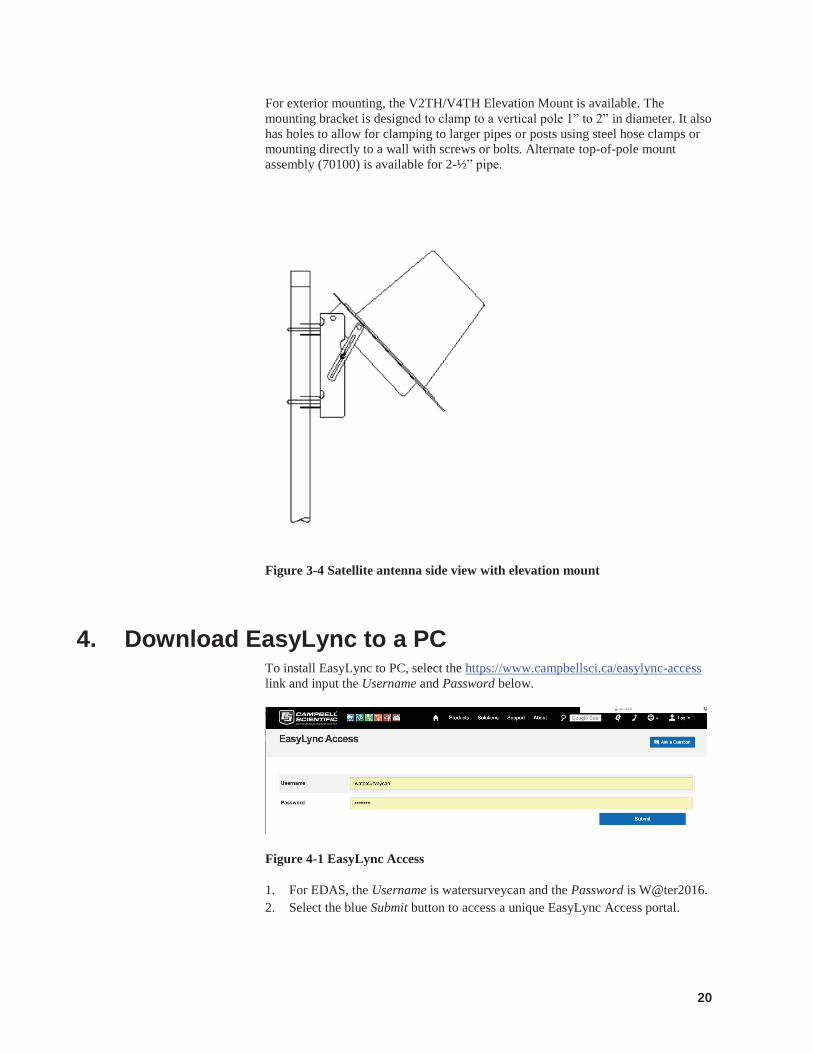
For exterior mounting, the V2TH/V4TH Elevation Mount is available. The mounting bracket is designed to clamp to a vertical pole 1” to 2” in diameter. It also has holes to allow for clamping to larger pipes or posts using steel hose clamps or mounting directly to a wall with screws or bolts. Alternate top-of-pole mount assembly (70100) is available for 2-½” pipe.
Figure 3-4 Satellite antenna side view with elevation mount
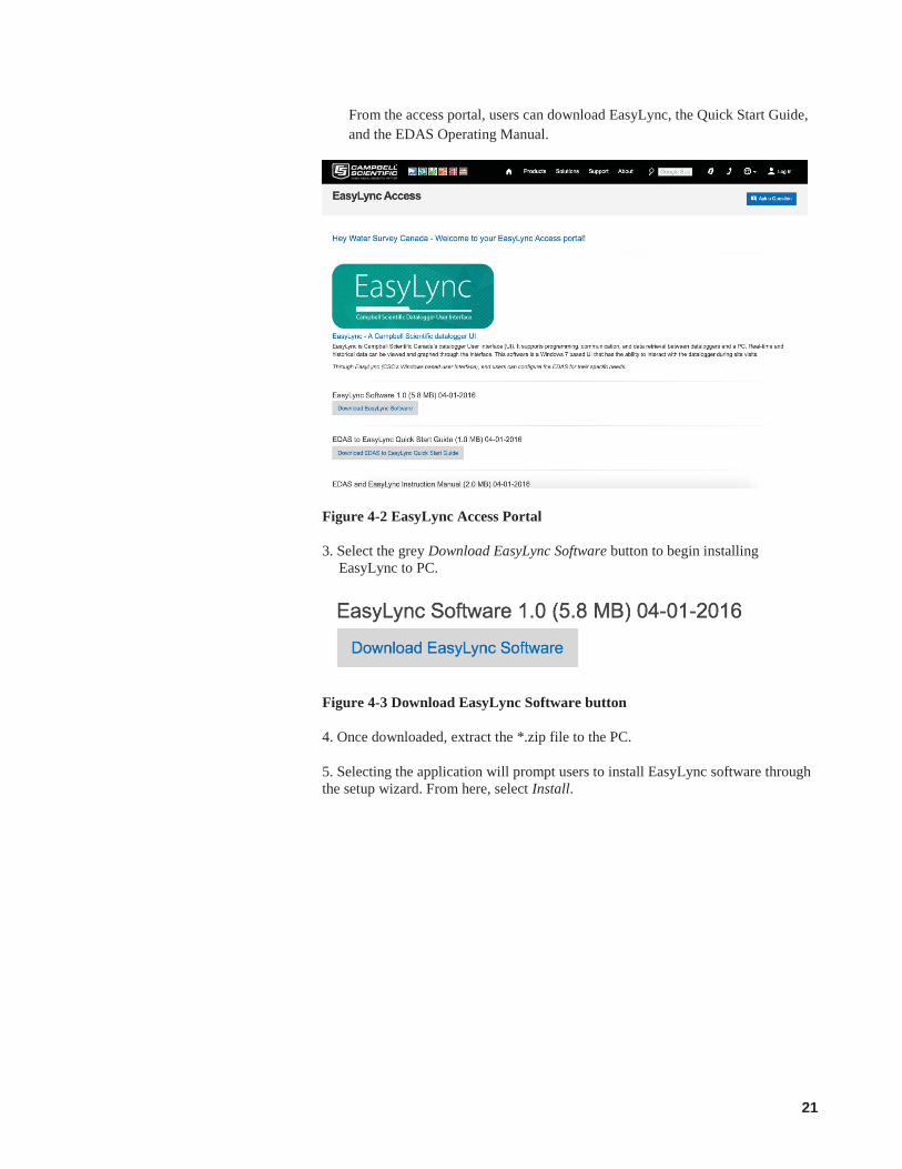
4. Download EasyLync to a PC To install EasyLync to PC, select the https://www.campbellsci.ca/easylync-access link and input the Username and Password below.
Figure 4-1 EasyLync Access
1. For EDAS, the Username is watersurveycan and the Password is W@ter2016. 2. Select the blue Submit button to access a unique EasyLync Access portal.
21
From the access portal, users can download EasyLync, the Quick Start Guide, and the EDAS Operating Manual.
Figure 4-2 EasyLync Access Portal
3. Select the grey Download EasyLync Software button to begin installing EasyLync to PC.
Figure 4-3 Download EasyLync Software button
4. Once downloaded, extract the *.zip file to the PC.
5. Selecting the application will prompt users to install EasyLync software through the setup wizard. From here, select Install.
22
Figure 4-4 EasyLync Setup Wizard Install
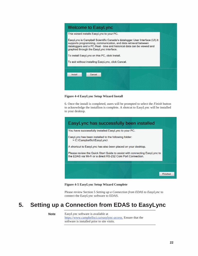
6. Once the install is completed, users will be prompted to select the Finish button to acknowledge the installion is complete. A shotcut to EasyLync will be installed to your desktop.
Figure 4-5 EasyLync Setup Wizard Complete
Please review Section 5 Setting up a Connection from EDAS to EasyLync to connect the EasyLync software to EDAS.
5. Setting up a Connection from EDAS to EasyLync EasyLync software is available at https://www.campbellsci.ca/easylync-access. Ensure that the software is installed prior to site visits.
Note
23
By establishing a wireless or direct connection, the EDAS can be fully configured using EasyLync software.
The EDAS station program monitors the parameters that are defined by users during the setup process using the EasyLync software. The parameters are collected in an interval that is defined by users. The data is recorded and stored on the datalogger, then transferred to a website via cellular telemetry.
5.1 Direct (RS-232) Connection (Com Port) to EDAS A direct or serial RS-232 connection is the preferred connection type as it provides the most reliable connection.
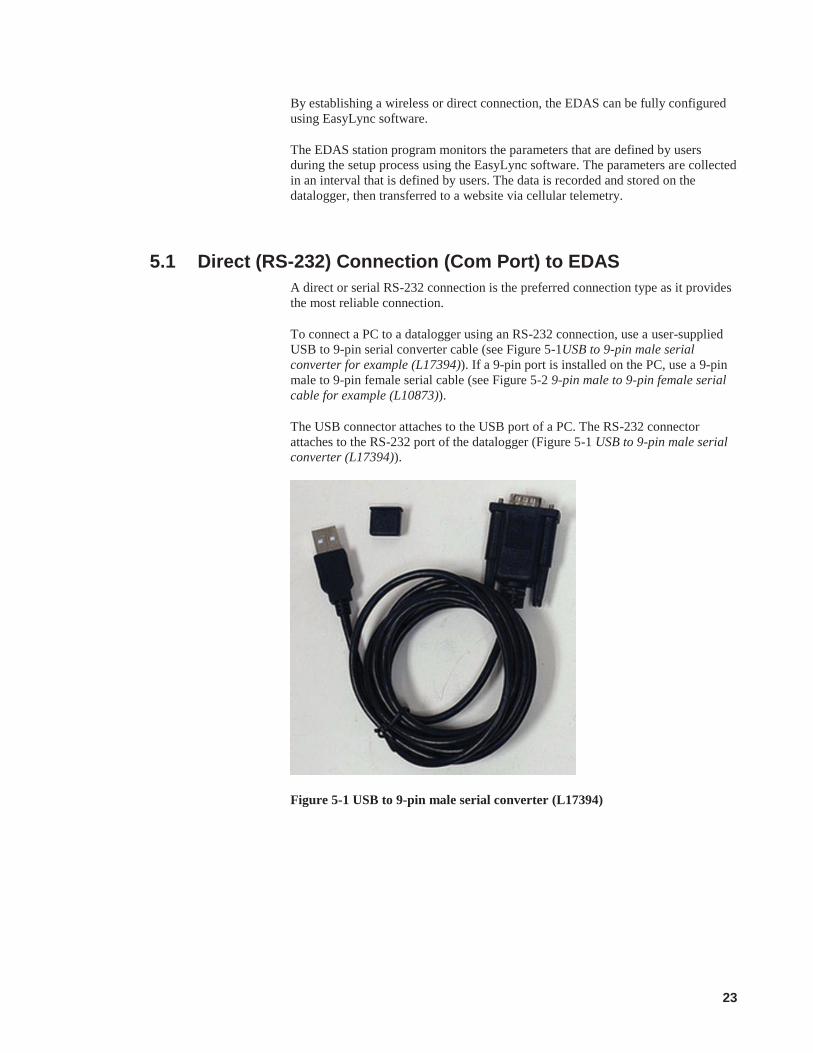
To connect a PC to a datalogger using an RS-232 connection, use a user-supplied USB to 9-pin serial converter cable (see Figure 5-1USB to 9-pin male serial converter for example (L17394)). If a 9-pin port is installed on the PC, use a 9-pin male to 9-pin female serial cable (see Figure 5-2 9-pin male to 9-pin female serial cable for example (L10873)).
The USB connector attaches to the USB port of a PC. The RS-232 connector attaches to the RS-232 port of the datalogger (Figure 5-1 USB to 9-pin male serial converter (L17394)).
Figure 5-1 USB to 9-pin male serial converter (L17394)

24
Figure 5-2 9-pin male to 9-pin female serial cable (L10873)
Make sure the driver for the USB to 9-pin serial converter is installed correctly before a site visit to ensure a direct connection is possible.
Drivers can typically be found on the manufacturer’s website. If an USB to 9-pin male serial converter cable (see Figure 5-1 USB to 9-pin male serial converter (L17394)) has been purchased from Campbell Scientific, the driver can be found at: http://www.campbellsci.ca/l17394
5.2 Wireless Connection Setup and Considerations A Setup button is provided on the EDAS enclosure (see Figure 2-3 Bottom View of Enclosure). Pushing the Setup button activates the Wi-Fi on the cellular modem. Once the Setup button is pressed, the modem will turn on within 10 seconds. Once the BulletPlus Cellular Modem is powered, it initiates its boot sequence, which can take up to two minutes. The Wi-Fi is defaulted to be active for 15 minutes in order to save power. This is configurable in the Manitaince tab of the cellular modem (see Section 6.5.2.2 Communcations: Cellular: Maintenance).
After this time, the EDAS Wi-Fi network should be visible and a wireless connection can be made. This allows users to make a wireless connection using a Windows 7 based PC. The Wi-Fi network may take up to two minutes to boot and will time out after 30 minutes by default. This timeout can be extended using EasyLync Settings (see Section 6.7 Settings). This is a power saving feature and eliminates the possibility of a modem being left on after a site visit is complete.
5.2.1 Wirelessly Connect to EDAS When an EDAS is supplied with the optional BulletPlus Cellular Modem, a Wi-Fi connection from EDAS to EasyLync can be established. This connection type is used when a direct RS-232 connection cannot be established (see Section 5.1 Direct (RS-232) Connection (Com Port) to EDAS).
1. Connect wirelessly to the EDAS by searching and selecting the wireless device in Windows using the Network Tool in the bottom right of the screen. By default, the name of the wireless network is Level I_II EDAS SNX, where X is the box serial number.
The wireless network will match the Station Name after the initial EDAS setup through EasyLync (see Section 6.7.1 Settings: Station Settings Tab).
Note
Note
25
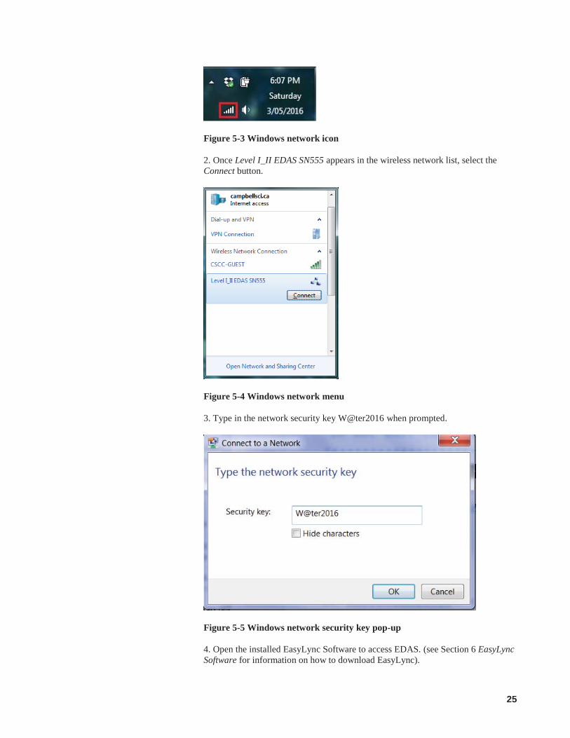
Figure 5-3 Windows network icon
2. Once Level I_II EDAS SN555 appears in the wireless network list, select the Connect button.
Figure 5-4 Windows network menu
3. Type in the network security key W@ter2016 when prompted.
Figure 5-5 Windows network security key pop-up
4. Open the installed EasyLync Software to access EDAS. (see Section 6 EasyLync Software for information on how to download EasyLync).
26
5. From the EasyLync Dashboard, specify IP as the Connection Type.
6. Enter the IP address 192.168.12.99 and select the Connect button on the Dashboard.
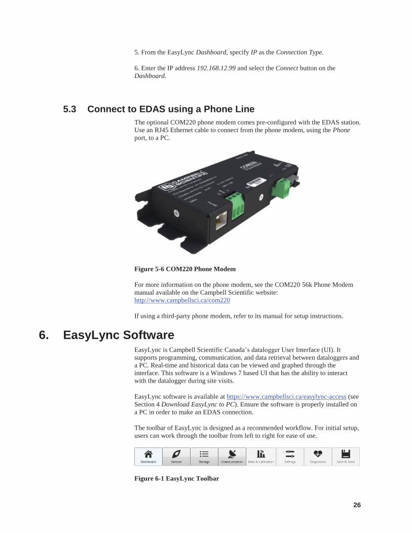
5.3 Connect to EDAS using a Phone Line The optional COM220 phone modem comes pre-configured with the EDAS station. Use an RJ45 Ethernet cable to connect from the phone modem, using the Phone port, to a PC.
Figure 5-6 COM220 Phone Modem
For more information on the phone modem, see the COM220 56k Phone Modem manual available on the Campbell Scientific website: http://www.campbellsci.ca/com220
If using a third-party phone modem, refer to its manual for setup instructions.
6. EasyLync Software EasyLync is Campbell Scientific Canada’s datalogger User Interface (UI). It supports programming, communication, and data retrieval between dataloggers and a PC. Real-time and historical data can be viewed and graphed through the interface. This software is a Windows 7 based UI that has the ability to interact with the datalogger during site visits.
EasyLync software is available at https://www.campbellsci.ca/easylync-access (see Section 4 Download EasyLync to PC). Ensure the software is properly installed on a PC in order to make an EDAS connection.
The toolbar of EasyLync is designed as a reconmended workflow. For initial setup, users can work through the toolbar from left to right for ease of use.
Figure 6-1 EasyLync Toolbar
27
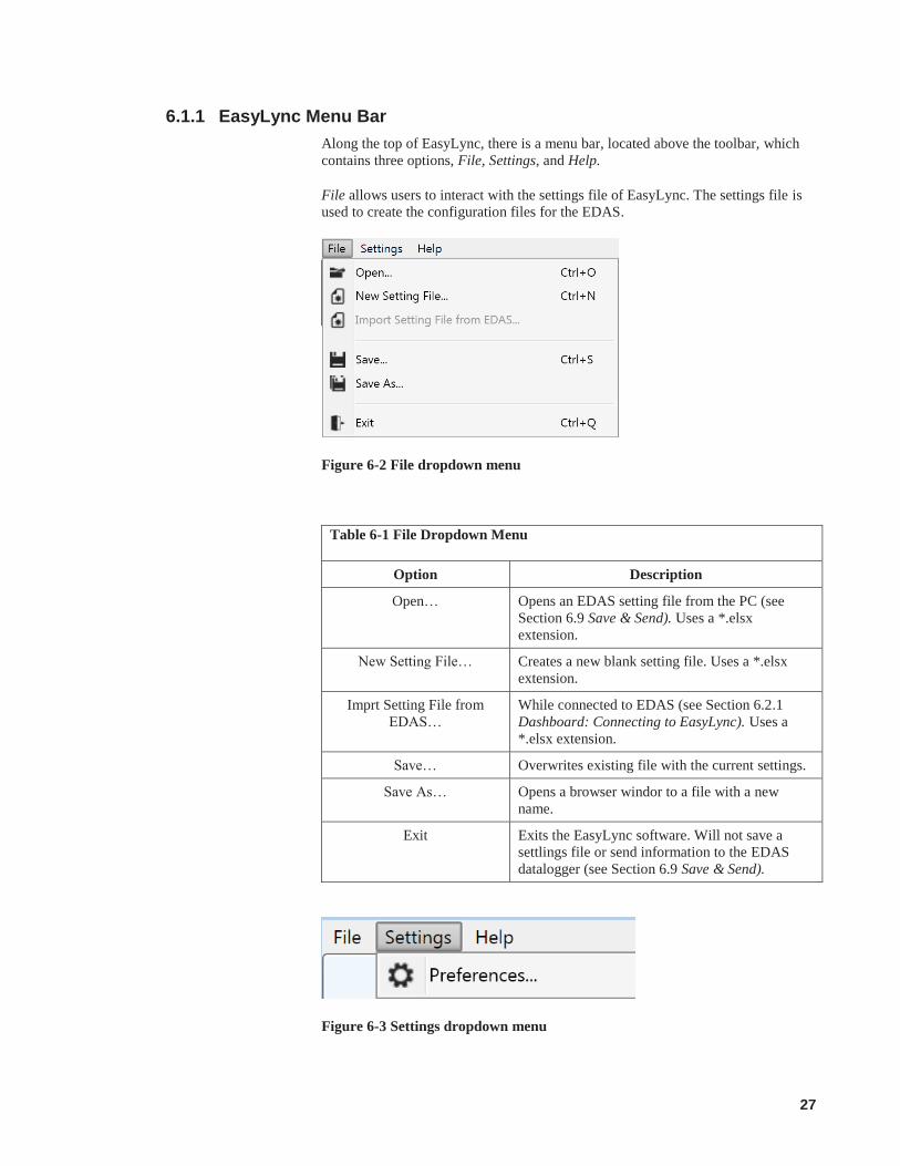
6.1.1 EasyLync Menu Bar Along the top of EasyLync, there is a menu bar, located above the toolbar, which contains three options, File, Settings, and Help.
File allows users to interact with the settings file of EasyLync. The settings file is used to create the configuration files for the EDAS.
Figure 6-2 File dropdown menu
Table 6-1 File Dropdown Menu
Option Description
Open… Opens an EDAS setting file from the PC (see Section 6.9 Save & Send). Uses a *.elsx extension.
New Setting File… Creates a new blank setting file. Uses a *.elsx extension.
Imprt Setting File from EDAS…
While connected to EDAS (see Section 6.2.1 Dashboard: Connecting to EasyLync). Uses a *.elsx extension.
Save… Overwrites existing file with the current settings.
Save As… Opens a browser windor to a file with a new name.
Exit Exits the EasyLync software. Will not save a settlings file or send information to the EDAS datalogger (see Section 6.9 Save & Send).
Figure 6-3 Settings dropdown menu
28
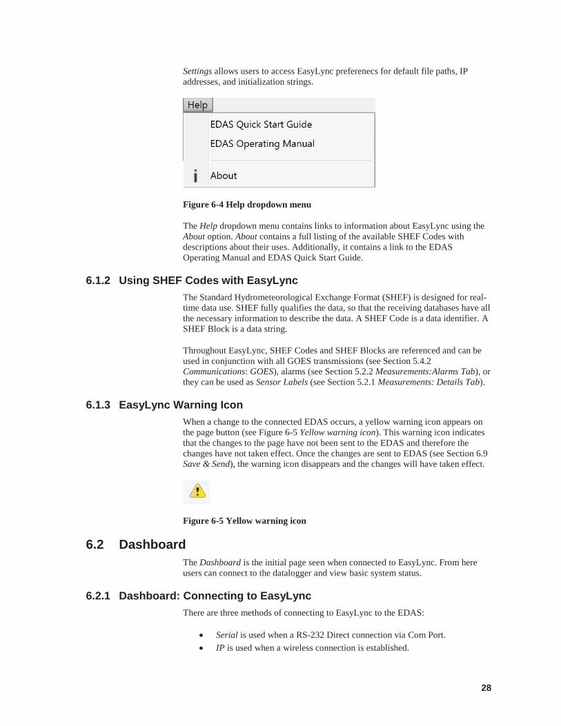
Settings allows users to access EasyLync preferenecs for default file paths, IP addresses, and initialization strings.
Figure 6-4 Help dropdown menu
The Help dropdown menu contains links to information about EasyLync using the About option. About contains a full listing of the available SHEF Codes with descriptions about their uses. Additionally, it contains a link to the EDAS Operating Manual and EDAS Quick Start Guide.
6.1.2 Using SHEF Codes with EasyLync The Standard Hydrometeorological Exchange Format (SHEF) is designed for real-time data use. SHEF fully qualifies the data, so that the receiving databases have all the necessary information to describe the data. A SHEF Code is a data identifier. A SHEF Block is a data string.
Throughout EasyLync, SHEF Codes and SHEF Blocks are referenced and can be used in conjunction with all GOES transmissions (see Section 5.4.2 Communications: GOES), alarms (see Section 5.2.2 Measurements:Alarms Tab), or they can be used as Sensor Labels (see Section 5.2.1 Measurements: Details Tab).
6.1.3 EasyLync Warning Icon When a change to the connected EDAS occurs, a yellow warning icon appears on the page button (see Figure 6-5 Yellow warning icon). This warning icon indicates that the changes to the page have not been sent to the EDAS and therefore the changes have not taken effect. Once the changes are sent to EDAS (see Section 6.9 Save & Send), the warning icon disappears and the changes will have taken effect.
Figure 6-5 Yellow warning icon
6.2 Dashboard The Dashboard is the initial page seen when connected to EasyLync. From here users can connect to the datalogger and view basic system status.
6.2.1 Dashboard: Connecting to EasyLync There are three methods of connecting to EasyLync to the EDAS:
Serial is used when a RS-232 Direct connection via Com Port. IP is used when a wireless connection is established.
29
Phone Line is used when connecting via a phone modem.
There is a fourth option in the Specify a Connection Type dropdown called Offline - Terminal mode which allows users to connect to EasyLync without an EDAS connection.
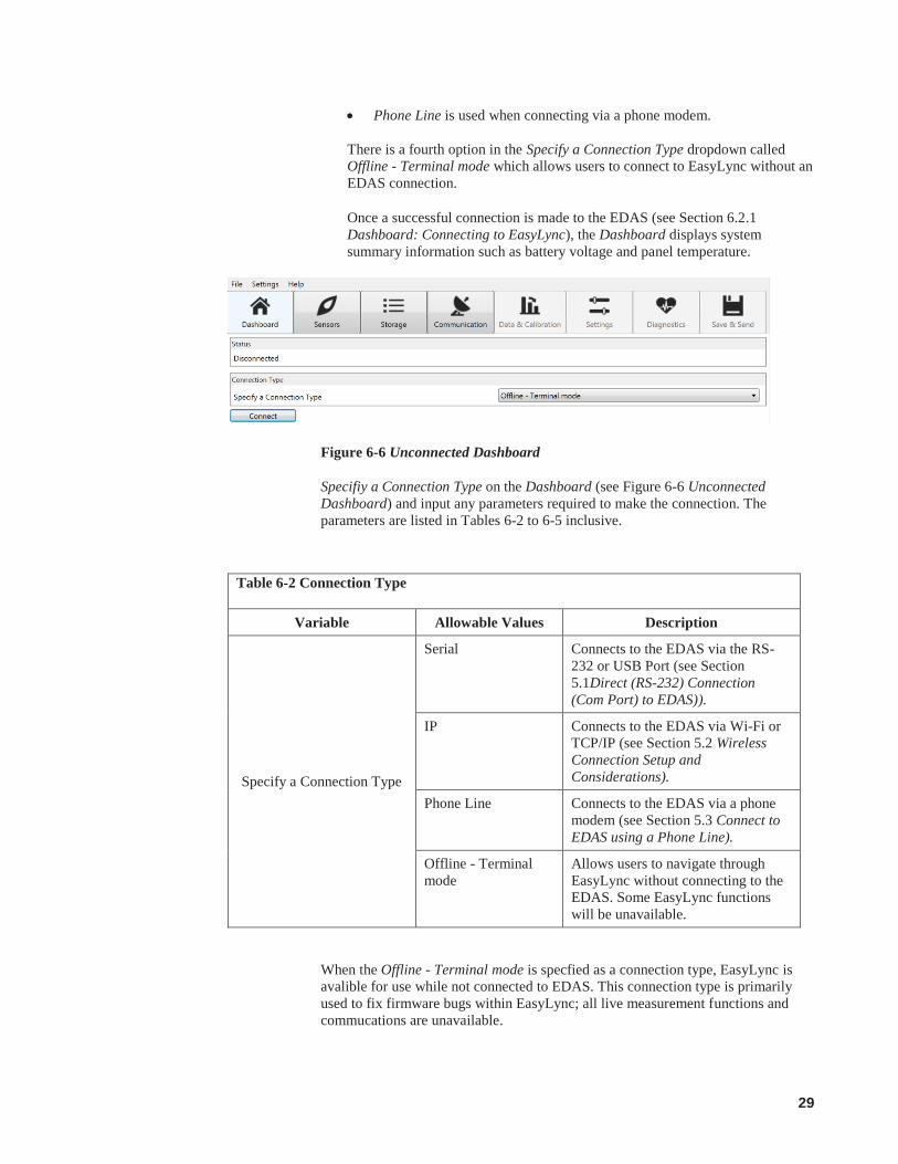
Once a successful connection is made to the EDAS (see Section 6.2.1 Dashboard: Connecting to EasyLync), the Dashboard displays system summary information such as battery voltage and panel temperature.
Figure 6-6 Unconnected Dashboard
Specifiy a Connection Type on the Dashboard (see Figure 6-6 Unconnected Dashboard) and input any parameters required to make the connection. The parameters are listed in Tables 6-2 to 6-5 inclusive.
When the Offline - Terminal mode is specfied as a connection type, EasyLync is avalible for use while not connected to EDAS. This connection type is primarily used to fix firmware bugs within EasyLync; all live measurement functions and commucations are unavailable.
Table 6-2 Connection Type
Variable Allowable Values Description
Specify a Connection Type
Serial Connects to the EDAS via the RS-232 or USB Port (see Section 5.1Direct (RS-232) Connection (Com Port) to EDAS)).
IP Connects to the EDAS via Wi-Fi or TCP/IP (see Section 5.2 Wireless Connection Setup and Considerations).
Phone Line Connects to the EDAS via a phone modem (see Section 5.3 Connect to EDAS using a Phone Line).
Offline - Terminal mode
Allows users to navigate through EasyLync without connecting to the EDAS. Some EasyLync functions will be unavailable.

30
When IP is specfied as a connection type, EasyLync connects to the EDAS via Wi-Fi or cellular.ethernet type connections (TCP/IP )(see Section 5.2 Wireless Connection Setup and Considerations). Enter the IP address 192.168.12.99 and select the Connect button on the Dashboard. Delay (seconds) adds seconds of delay to increase connection reliability.
Figure 6-7 Dashboard: IP Connection Configuration
When Phone Line is specfied as a connection type, EasyLync connects to the EDAS via a phone modem (see Section 5.3 Connect to EDAS using a Phone Line).
Figure 6-8 Phone Line Configuration
Table 6-3 Phone Line Configuration
Variable Allowable Values
Description
Dialing Number Numerical Allows users to input their 10 digit phone number associated with the phone line.
COM Port Dropdown Allows users to select a Com Port for internal or external modems.
Modem Registration String Numerical Allows users to enter modem initialization strings.
Delay (seconds) Numerical Adds seconds of delay to increase connection reliability
Connect Button Initializes connection to datalogger based on user-defined settings.
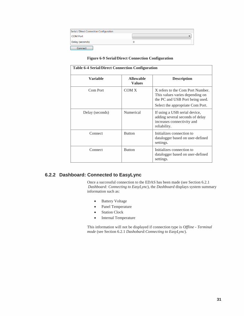
When Serial is specfied as a connection type, EasyLync connects to the EDAS via RS-232 or USB Port (see Section 5.1Direct (RS-232) Connection (Com Port) to EDAS).
31
Figure 6-9 Serial/Direct Connection Configuration
Table 6-4 Serial/Direct Connection Configuration
Variable Allowable Values
Description
Com Port COM X X refers to the Com Port Number. This values varies depending on the PC and USB Port being used. Select the appropriate Com Port.
Delay (seconds) Numerical If using a USB serial device, adding several seconds of delay increases connectivity and reliability.
Connect Button Initializes connection to datalogger based on user-defined settings.
Connect Button Initializes connection to datalogger based on user-defined settings.
6.2.2 Dashboard: Connected to EasyLync Once a successful connection to the EDAS has been made (see Section 6.2.1 Dashboard: Connecting to EasyLync), the Dashboard displays system summary information such as:
Battery Voltage Panel Temperature Station Clock Internal Temperature
This information will not be displayed if connection type is Offline - Terminal mode (see Section 6.2.1 Dashobard:Connecting to EasyLync).
32
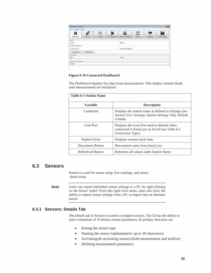
Figure 6-10 Connected Dashboard
The Dashboard displays live data from measurements. This display remains blank until measurements are initialized.
Table 6-5 Station Name
Variable Description
Connected Displays the station name as defined in Settings (see Section 5.6.1 Settings: Station Settings Tab). Default is blank.
Com Port Displays the Com Port used as defined when connected to EasyLync as Serial (see Table 6-2 Connection Type).
Station Clock Displays current clock time.
Disconnect Button Disconnects users from EasyLync.
Refresh all Button Refreshes all values under Station Name.
6.3 Sensors Sensors is used for sensor setup, live readings, and sensor alarm setup.
Users can export individual sensor settings to a PC by right-clicking on the Sensor Label. From this right-click menu, users also have the ability to import sensor settings from a PC to import into an alternate sensor.
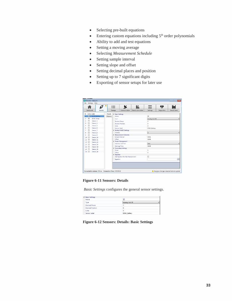
6.3.1 Sensors: Details Tab The Details tab in Sensors is used to configure sensors. The UI has the ability to store a minimum of 10 distinct sensor parameters. Its primary functions are:
Setting the sensor type Naming the sensor (alphanumeric up to 30 characters) Activating/de-activating sensors (both measurement and archive) Defining measurement parameters
Note
33
Selecting pre-built equations Entering custom equations including 5th order polynomials Ability to add and test equations Setting a moving average Selecting Measurement Schedule Setting sample interval Setting slope and offset Setting decimal places and position Setting up to 7 significant digits Exporting of sensor setups for later use
Figure 6-11 Sensors: Details
Basic Settings configures the general sensor settings.
Figure 6-12 Sensors: Details: Basic Settings
34
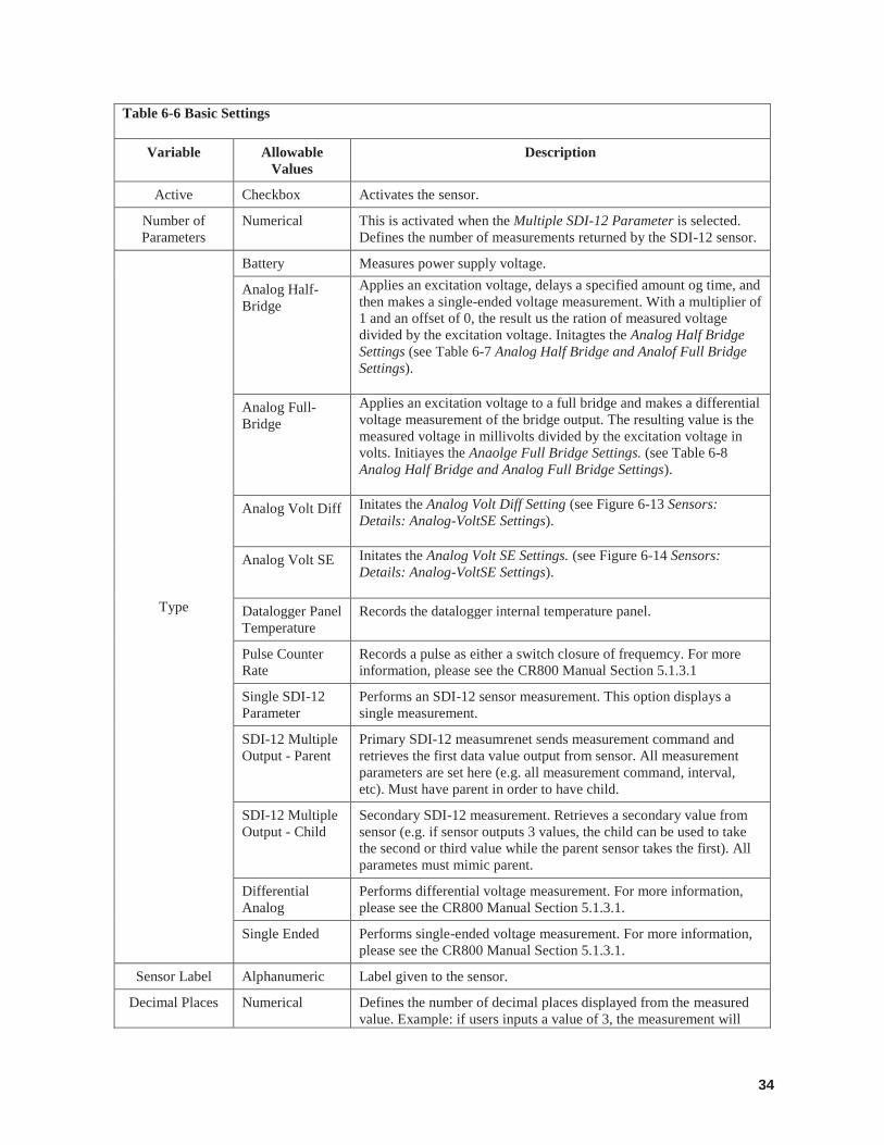
Table 6-6 Basic Settings
Variable Allowable Values
Description
Active Checkbox Activates the sensor.
Number of Parameters
Numerical This is activated when the Multiple SDI-12 Parameter is selected. Defines the number of measurements returned by the SDI-12 sensor.
Type
Battery Measures power supply voltage.
Analog Half-Bridge
Applies an excitation voltage, delays a specified amount og time, and then makes a single-ended voltage measurement. With a multiplier of 1 and an offset of 0, the result us the ration of measured voltage divided by the excitation voltage. Initagtes the Analog Half Bridge Settings (see Table 6-7 Analog Half Bridge and Analof Full Bridge Settings).
Analog Full-Bridge
Applies an excitation voltage to a full bridge and makes a differential voltage measurement of the bridge output. The resulting value is the measured voltage in millivolts divided by the excitation voltage in volts. Initiayes the Anaolge Full Bridge Settings. (see Table 6-8 Analog Half Bridge and Analog Full Bridge Settings).
Analog Volt Diff Initates the Analog Volt Diff Setting (see Figure 6-13 Sensors: Details: Analog-VoltSE Settings).
Analog Volt SE Initates the Analog Volt SE Settings. (see Figure 6-14 Sensors: Details: Analog-VoltSE Settings).
Datalogger Panel Temperature
Records the datalogger internal temperature panel.
Pulse Counter Rate
Records a pulse as either a switch closure of frequemcy. For more information, please see the CR800 Manual Section 5.1.3.1
Single SDI-12 Parameter
Performs an SDI-12 sensor measurement. This option displays a single measurement.
SDI-12 Multiple Output - Parent
Primary SDI-12 measumrenet sends measurement command and retrieves the first data value output from sensor. All measurement parameters are set here (e.g. all measurement command, interval, etc). Must have parent in order to have child.
SDI-12 Multiple Output - Child
Secondary SDI-12 measurement. Retrieves a secondary value from sensor (e.g. if sensor outputs 3 values, the child can be used to take the second or third value while the parent sensor takes the first). All parametes must mimic parent.
Differential Analog
Performs differential voltage measurement. For more information, please see the CR800 Manual Section 5.1.3.1.
Single Ended Performs single-ended voltage measurement. For more information, please see the CR800 Manual Section 5.1.3.1.
Sensor Label Alphanumeric Label given to the sensor.
Decimal Places Numerical Defines the number of decimal places displayed from the measured value. Example: if users inputs a value of 3, the measurement will
35
display to the third decimal place – 0.123. Default is 0.
Decimal Positions
Numerical Moves a decimal point by a factor of +/- 10. Example: if users input a value of 3, the measurement value will change from 30 000 to 30.000. Default value is 0.
Units Alphanumeric Defines the units associated with the measurement based on the sensor manuals. Example: W/m2 is Watts per meter squared.
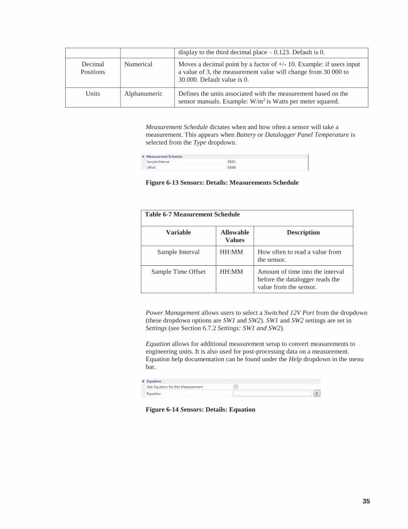
Measurement Schedule dictates when and how often a sensor will take a measurement. This appears when Battery or Datalogger Panel Temperature is selected from the Type dropdown.
Figure 6-13 Sensors: Details: Measurements Schedule
Table 6-7 Measurement Schedule
Variable Allowable Values
Description
Sample Interval HH:MM How often to read a value from the sensor.
Sample Time Offset HH:MM Amount of time into the interval before the datalogger reads the value from the sensor.
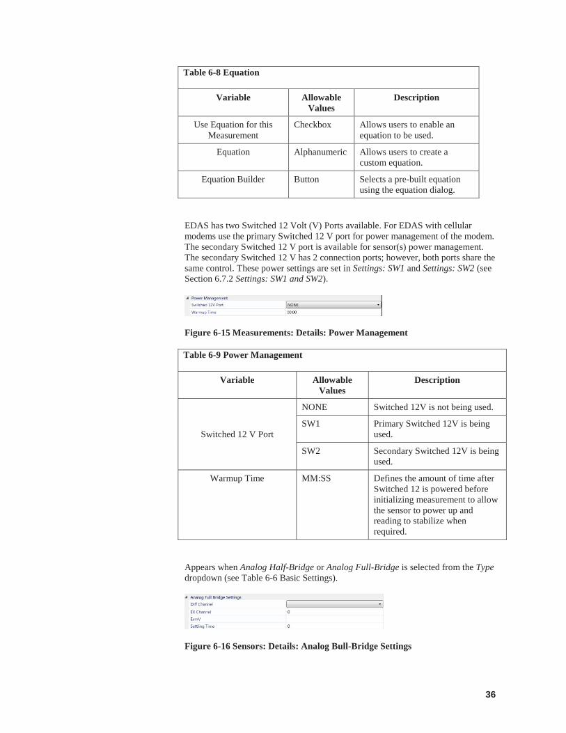
Power Management allows users to select a Switched 12V Port from the dropdown (these dropdown options are SW1 and SW2). SW1 and SW2 settings are set in Settings (see Section 6.7.2 Settings: SW1 and SW2).
Equation allows for additional measurement setup to convert measurements to engineering units. It is also used for post-processing data on a measurement. Equation help documentation can be found under the Help dropdown in the menu bar.
Figure 6-14 Sensors: Details: Equation
36
Table 6-8 Equation
Variable Allowable Values
Description
Use Equation for this Measurement
Checkbox Allows users to enable an equation to be used.
Equation Alphanumeric Allows users to create a custom equation.
Equation Builder Button Selects a pre-built equation using the equation dialog.
EDAS has two Switched 12 Volt (V) Ports available. For EDAS with cellular modems use the primary Switched 12 V port for power management of the modem. The secondary Switched 12 V port is available for sensor(s) power management. The secondary Switched 12 V has 2 connection ports; however, both ports share the same control. These power settings are set in Settings: SW1 and Settings: SW2 (see Section 6.7.2 Settings: SW1 and SW2).
Figure 6-15 Measurements: Details: Power Management
Table 6-9 Power Management
Variable Allowable Values
Description
Switched 12 V Port
NONE Switched 12V is not being used.
SW1 Primary Switched 12V is being used.
SW2 Secondary Switched 12V is being used.
Warmup Time MM:SS Defines the amount of time after Switched 12 is powered before initializing measurement to allow the sensor to power up and reading to stabilize when required.
Appears when Analog Half-Bridge or Analog Full-Bridge is selected from the Type dropdown (see Table 6-6 Basic Settings).
Figure 6-16 Sensors: Details: Analog Bull-Bridge Settings

37
Table 6-10 Analog Half Bridge and Analog Full Bridge Settings
Variable Allowable Values
Description
Diff Channel Dropdown Displays values from 1-3. These are the available Differnetial Channels on the datalogger for sensor connection. On the physical EDAS datalogger, the analog inputs are labeled as DIFF1-DIFF3 (see Figure 2-7 Avaliable CR850-XT sensor ports).
Excitation Channel Numerical EX1-EX2 display by default. These are the available excitation channels on the datalogger for sensor connection.
Excitation in mV (will excite positive and negative)
Numerical Excitation output from the sensor. Used for sensors which require excitation.
Setting Time mSec (leave at 0 or set to 3mSec to
50mSec)
Numerical The amount of time to allow for signal setting after setting up a measurement (switching to the channel, setting the excitation) and before making the measurement.
Appears when Analog Volt Diff or Analog Volt SE is selected from the Type dropdown (see Table 6-6 Basic Settings).
Figure 6-17 Sensors: Details: Analog-VoltSE Settings
The Channel dropdown displays values from 1-6 when Analog VoltSE is selected from the Type dropdown(see Table 6-6 Basic Settings). These are the channels on the datalogger for sensor connection.
The Channel dropdown displays values from 1-3 when Analog VoltDiff is selected from the Type dropdown(see Table 6-6 Basic Settings ). These are the channels on the datalogger for sensor connection.
Use the Processing Settings to convert raw measurements to useable engineering units.
Figure 6-18 Sensors: Details: Processing Settings
38
Table 6-11 Processing Settings
Variable Allowable Values
Description
Slope Numerical Default slope is 1.
Offset Numerical Default offsite is 0.
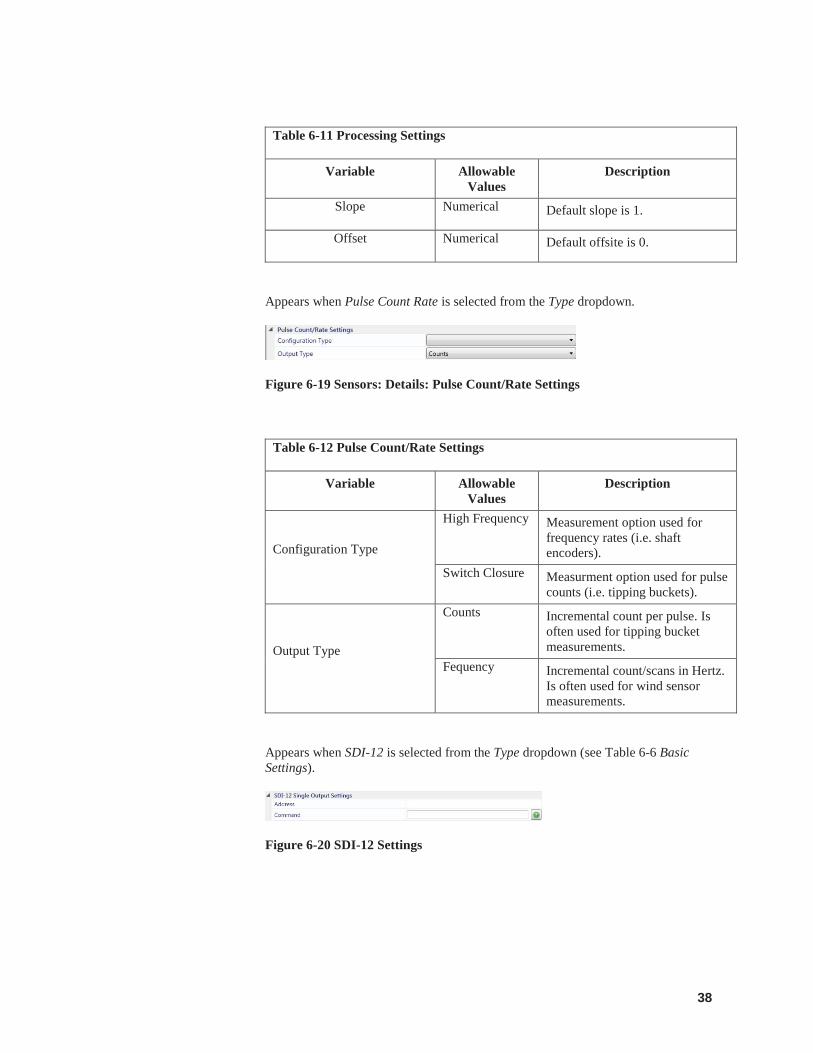
Appears when Pulse Count Rate is selected from the Type dropdown.
Figure 6-19 Sensors: Details: Pulse Count/Rate Settings
Table 6-12 Pulse Count/Rate Settings
Variable Allowable Values
Description
Configuration Type
High Frequency Measurement option used for frequency rates (i.e. shaft encoders).
Switch Closure Measurment option used for pulse counts (i.e. tipping buckets).
Output Type
Counts Incremental count per pulse. Is often used for tipping bucket measurements.
Fequency Incremental count/scans in Hertz. Is often used for wind sensor measurements.
Appears when SDI-12 is selected from the Type dropdown (see Table 6-6 Basic Settings).
Figure 6-20 SDI-12 Settings

39
Table 6-13 SDI-12 Settings
Variable Allowable Values
Description
Address Text Address of SDI-12 sensor. This is defaulted to 0 by the sensor manufacturer.
Command Text Command sent to the sensor to initialize measurement or query (e.g. “?!” generally does an address query).
Figure 6-21 SDI-12 Multiple Output Parent Settings
Appears when SDI-12 Multiple Output – Parent is selected from the Type dropdown (see Table 6-6 Basic Settings).
Table 6-14 SDI-12 Multiple Output Parent Settings
Variable Allowable Values
Description
Address Text Address of SDI-12 sensor. This is generally defaulted to 0 by the sensor manufacturer.
Command Text Command sent to the sensor to initialize measurement or query (e.g. “?!” generally does an address query).
Number of Data Values Numerical The amount of data values outputted by the parent SDI-12 sensor.
Figure 6-22 SDI-12 Multiple Output Child Settings
40
Table 6-15 SDI-12 Multiple Output Child Settings
Variable Allowable Values
Description
SDI-12 Multiple Output – Parent
Dropdown Dropdown populates from the configured parent sensor. It allows users to select a parent to associate the child sensor with.
Output Value of Parent Numerical Return data value from sensor selected from the SDI-12 Multiple Out – Parent dropdown (e.g. use child to retrieve values from 2 or 3 from a sensor that has 3 outputs).
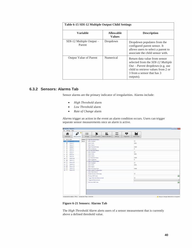
6.3.2 Sensors: Alarms Tab Sensor alarms are the primary indicator of irregularities. Alarms include:
High Threshold alarm Low Threshold alarm Rate of Change alarm
Alarms trigger an action in the event an alarm condition occurs. Users can trigger separate sensor measurements once an alarm is active.
Figure 6-21 Sensors: Alarms Tab
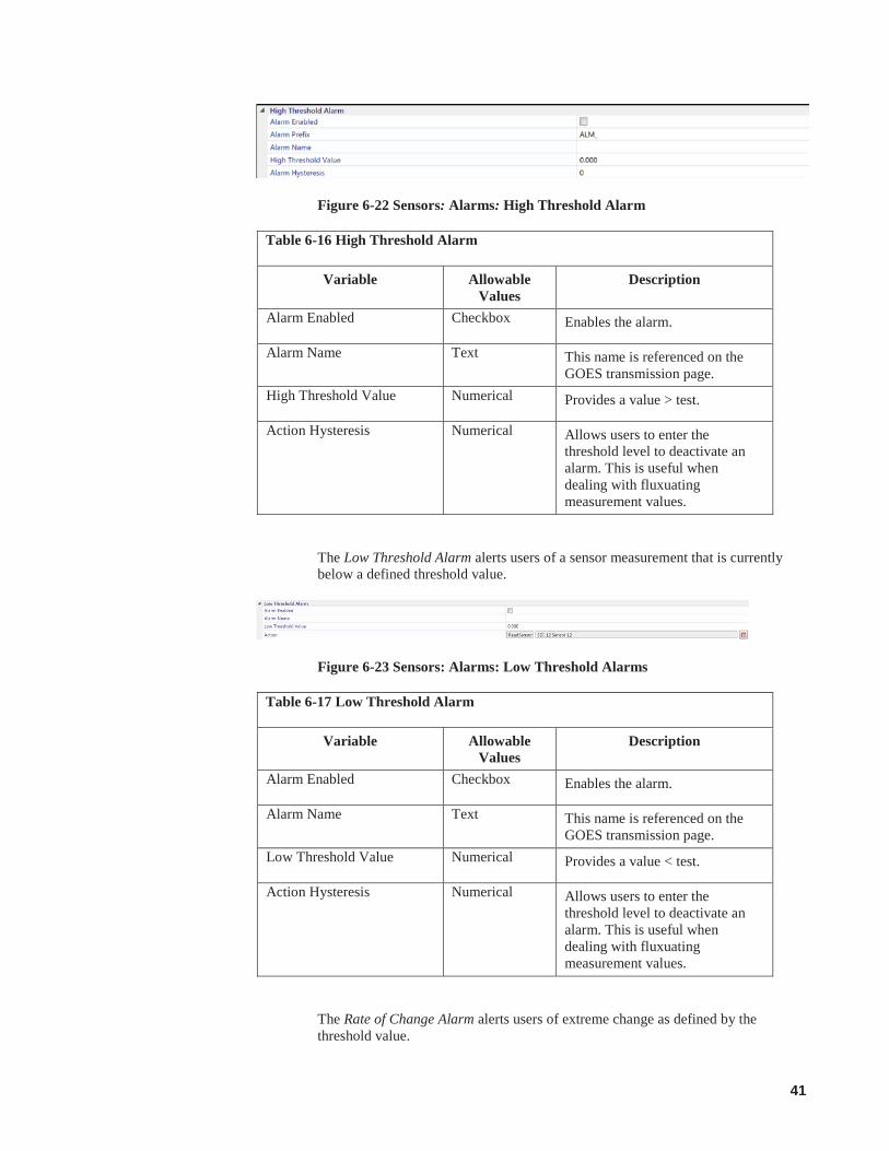
The High Threshold Alarm alerts users of a sensor measurement that is currently above a defined threshold value.
41
Figure 6-22 Sensors: Alarms: High Threshold Alarm
Table 6-16 High Threshold Alarm
Variable Allowable Values
Description
Alarm Enabled Checkbox Enables the alarm.
Alarm Name Text This name is referenced on the GOES transmission page.
High Threshold Value Numerical Provides a value > test.
Action Hysteresis Numerical Allows users to enter the threshold level to deactivate an alarm. This is useful when dealing with fluxuating measurement values.
The Low Threshold Alarm alerts users of a sensor measurement that is currently below a defined threshold value.
Figure 6-23 Sensors: Alarms: Low Threshold Alarms
Table 6-17 Low Threshold Alarm
Variable Allowable Values
Description
Alarm Enabled Checkbox Enables the alarm.
Alarm Name Text This name is referenced on the GOES transmission page.
Low Threshold Value Numerical Provides a value < test.
Action Hysteresis Numerical Allows users to enter the threshold level to deactivate an alarm. This is useful when dealing with fluxuating measurement values.
The Rate of Change Alarm alerts users of extreme change as defined by the threshold value.
42
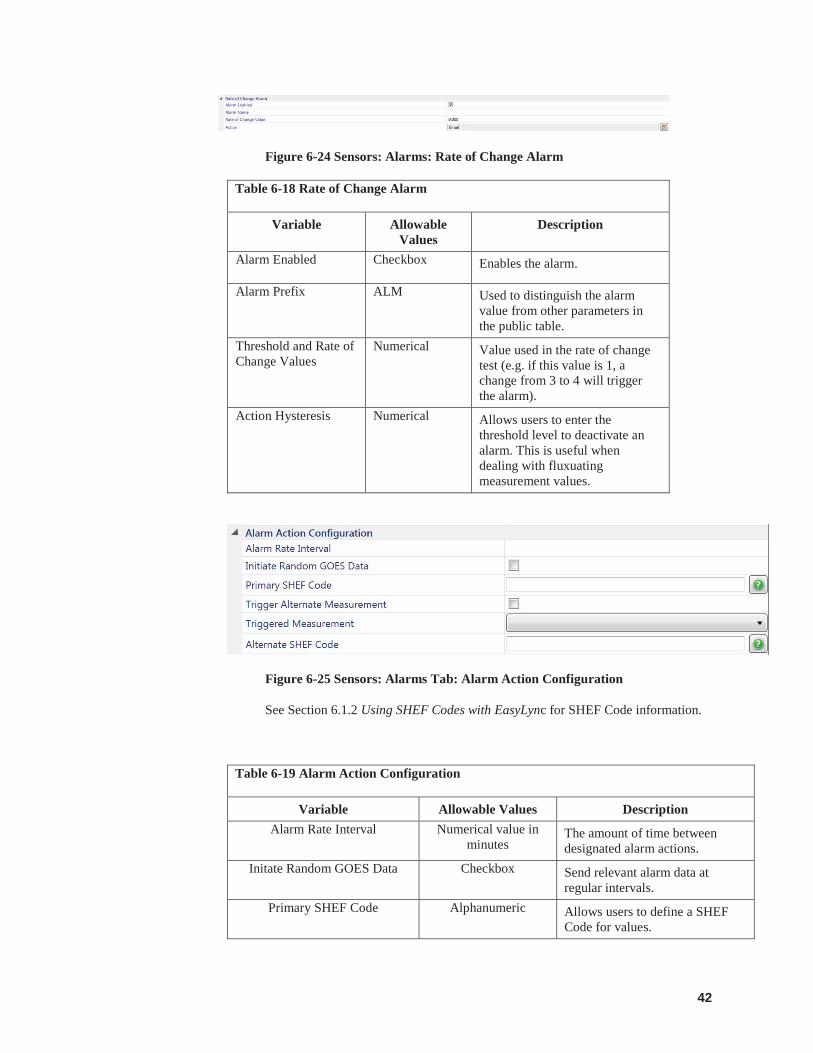
Figure 6-24 Sensors: Alarms: Rate of Change Alarm
Table 6-18 Rate of Change Alarm
Variable Allowable Values
Description
Alarm Enabled Checkbox Enables the alarm.
Alarm Prefix ALM Used to distinguish the alarm value from other parameters in the public table.
Threshold and Rate of Change Values
Numerical Value used in the rate of change test (e.g. if this value is 1, a change from 3 to 4 will trigger the alarm).
Action Hysteresis Numerical Allows users to enter the threshold level to deactivate an alarm. This is useful when dealing with fluxuating measurement values.
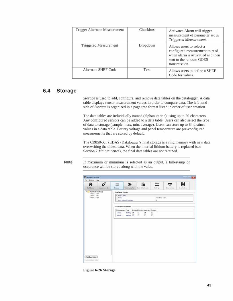
Figure 6-25 Sensors: Alarms Tab: Alarm Action Configuration
See Section 6.1.2 Using SHEF Codes with EasyLync for SHEF Code information.
Table 6-19 Alarm Action Configuration
Variable Allowable Values Description Alarm Rate Interval Numerical value in
minutes The amount of time between designated alarm actions.
Initate Random GOES Data Checkbox Send relevant alarm data at regular intervals.
Primary SHEF Code Alphanumeric Allows users to define a SHEF Code for values.
43
Trigger Alternate Measurement Checkbox Activates Alarm will trigger measurement of parameter set in Triggered Measurement.
Triggered Measurement Dropdown Allows users to select a configured measurement to read when alarm is activatied and then sent to the random GOES transmission.
Alternate SHEF Code Text Allows users to define a SHEF Code for values.
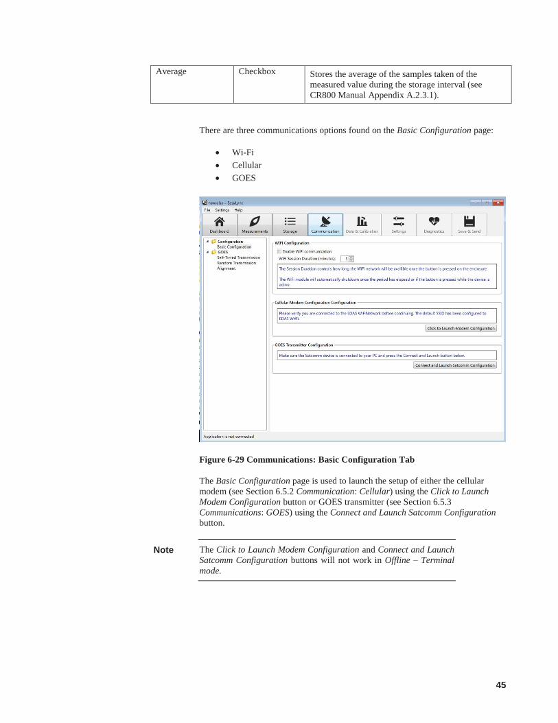
6.4 Storage Storage is used to add, configure, and remove data tables on the datalogger. A data table displays sensor measurement values in order to compare data. The left hand side of Storage is organized in a page tree format listed in order of user creation.
The data tables are individually named (alphanumeric) using up to 20 characters. Any configured sensors can be added to a data table. Users can also select the type of data to storage (sample, max, min, average). Users can store up to 64 distinct values in a data table. Battery voltage and panel temperature are pre-configured measurements that are stored by default.
The CR850-XT (EDAS) Datalogger’s final storage is a ring memory with new data overwriting the oldest data. When the internal lithium battery is replaced (see Section 7 Maintainence), the final data tables are not retained.
If maximum or minimum is selected as an output, a timestamp of occurance will be stored along with the value.
Figure 6-26 Storage
Note

44
When opening Storage, select the New Data Table button from the bottom left to begin building a new data table to store sensor measurements.
Data Table - Details allows users to name the data table for easy reference and for a data interval input.
Figure 6-27 Storage: Data Table – Details
The Name is used for reference to the data table and names data files. The Name also appears in Data Tables in the Table Monitor tab.
Data Interval (minutes) defines how often data is written to Storage.
Available Storage Options shows users the allowable storage types to add to the data table from the configured sensors in Measurements (see Section 6.3.1 Sensors: Details Tab).
Figure 6-28 Storage: Details: Available Measurements
6.5 Communications Communications is used configure the EDAS for local or remote data transfer.
Table 6-20 Available Measurements
Variable Allowable Values
Description
Measurement Read Only Displays measurement set in Measurements (see Section 6.3.1 Sensors:Details tab).
Type Read Only Displays sensor type set in Measurements (see Section 6.3.1 Sensors:Details tab).
Sample Checkbox Stores the data measurement value taken from a sensor at a single point and time.
Minimum Checkbox Stores the lowest measured value during the storage interval (see CR800 Manual Appendix A.2.3.1). This value is stored with the timestamp of occurance.
Maximum Checkbox Stores the highest measured value during the storage interval (see CR800 Manual Appendix A.2.3.1). This value is stored with the timestamp of occurance.
45
Average Checkbox Stores the average of the samples taken of the measured value during the storage interval (see CR800 Manual Appendix A.2.3.1).
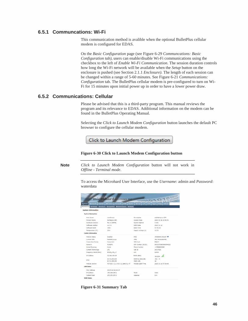
There are three communications options found on the Basic Configuration page:
Wi-Fi Cellular GOES
Figure 6-29 Communications: Basic Configuration Tab
The Basic Configuration page is used to launch the setup of either the cellular modem (see Section 6.5.2 Communication: Cellular) using the Click to Launch Modem Configuration button or GOES transmitter (see Section 6.5.3 Communications: GOES) using the Connect and Launch Satcomm Configuration button.
The Click to Launch Modem Configuration and Connect and Launch Satcomm Configuration buttons will not work in Offline – Terminal mode.
Note
46
6.5.1 Communcations: Wi-Fi This communication method is avalible when the optional BulletPlus cellular modem is configured for EDAS.
On the Basic Configuration page (see Figure 6-29 Communcations: Basic Configuration tab), users can enable/disable Wi-Fi communications using the checkbox to the left of Enable Wi-Fi Communication. The session duration controls how long the Wi-Fi network will be available when the Setup button on the enclosure is pushed (see Section 2.1.1 Enclosure). The length of each session can be changed within a range of 5-60 minutes. See Figure 6-21 Communications: Configuration tab. The BulletPlus cellular modem is pre-configured to turn on Wi-Fi for 15 minutes upon initial power up in order to have a lower power draw.
6.5.2 Communications: Cellular Please be advised that this is a third-party program. This manual reviews the program and its relevance to EDAS. Additional information on the modem can be found in the BulletPlus Operating Manual.
Selecting the Click to Launch Modem Configuration button launches the default PC browser to configure the cellular modem.
Figure 6-30 Click to Launch Modem Configuration button
Click to Launch Modem Configuration button will not work in Offline - Terminal mode.
To access the Microhard User Interface, use the Username: admin and Password: waterdata
Figure 6-31 Summary Tab
Note

47
Once the Microhard User Interface has loaded, click on the Carrier tab and go to Settings. Enter the APN, User Name, and Password (if applicable) as supplied by the phone carrier (i.e. Telus, Rogers, or Bell). Click Submit to save settings.
Once the settings are saved, reset the cellular modem. The changes will take effect and the modem will register on the Wi-Fi network and be ready for use. Check that the cellular modem is connected using the Microhard User Interface Summary tab.
For most EDAS applications, users only need to make changes under the Settings and Maintenance tabs; however, more advanced applications may need to be enabled for additional functionality of the modem. See BulletPlus Manual for full details on all the cellular modem functionalities.
It is recommended to discuss the available account types and their requirements with your intended phone carrier before configuring the cellular modem.
Modems are pre-configured for EDAS. It is not recommended to reset to default. If reset to defaut call Campbell Scientific Canada for support.
6.5.2.1 Communications: Cellular: Settings The Settings tab allows users to input the Access Point Name (APN) address, which is supplied by the phone carrier when an account is setup.
Figure 6-32 Cellular Settings Tab
Note
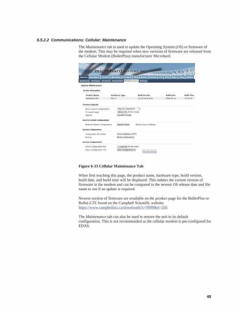
48
6.5.2.2 Communications: Cellular: Maintenance The Maintenance tab is used to update the Operating System (OS) or firmware of the modem. This may be required when new versions of firmware are released from the Cellular Modem (BulletPlus) manufacturer Microhard.
Figure 6-33 Cellular Maintenance Tab
When first reaching this page, the product name, hardware type, build version, build date, and build time will be displayed. This indates the current version of firmware in the modem and can be compared to the newest OS release date and file name to see if an update is required.
Newest version of firmware are available on the product page for the BulletPlus or Bullet-LTE found on the Campbell Scientific website: https://www.campbellsci.ca/downloads?c=9999&d=356
The Maintenance tab can also be used to restore the unit to its default configuration. This is not recommended as the cellular modem is pre-configured for EDAS.
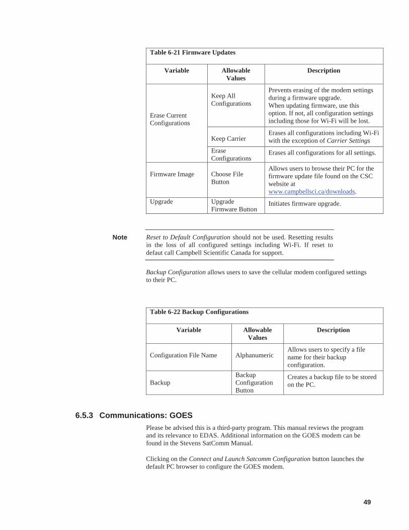
49
Table 6-21 Firmware Updates
Variable Allowable Values
Description
Erase Current Configurations
Keep All Configurations
Prevents erasing of the modem settings during a firmware upgrade. When updating firmware, use this option. If not, all configuration settings including those for Wi-Fi will be lost.
Keep Carrier
Erases all configurations including Wi-Fi with the exception of Carrier Settings
Erase Configurations
Erases all configurations for all settings.
Firmware Image
Choose File Button
Allows users to browse their PC for the firmware update file found on the CSC website at www.campbellsci.ca/downloads.
Upgrade Upgrade Firmware Button
Initiates firmware upgrade.
Reset to Default Configuration should not be used. Resetting results in the loss of all configured settings including Wi-Fi. If reset to defaut call Campbell Scientific Canada for support.
Backup Configuration allows users to save the cellular modem configured settings to their PC.
Table 6-22 Backup Configurations
Variable Allowable Values
Description
Configuration File Name
Alphanumeric
Allows users to specify a file name for their backup configuration.
Backup
Backup Configuration Button
Creates a backup file to be stored on the PC.
6.5.3 Communications: GOES Please be advised this is a third-party program. This manual reviews the program and its relevance to EDAS. Additional information on the GOES modem can be found in the Stevens SatComm Manual.
Clicking on the Connect and Launch Satcomm Configuration button launches the default PC browser to configure the GOES modem.
Note
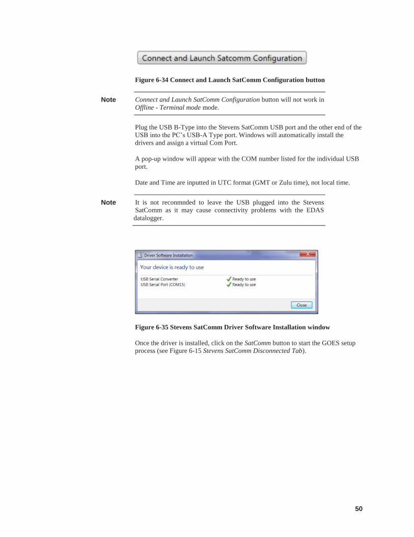
50
Figure 6-34 Connect and Launch SatComm Configuration button
Connect and Launch SatComm Configuration button will not work in Offline - Terminal mode mode.
Plug the USB B-Type into the Stevens SatComm USB port and the other end of the USB into the PC’s USB-A Type port. Windows will automatically install the drivers and assign a virtual Com Port.
A pop-up window will appear with the COM number listed for the individual USB port.
Date and Time are inputted in UTC format (GMT or Zulu time), not local time.
It is not reconmnded to leave the USB plugged into the Stevens SatComm as it may cause connectivity problems with the EDAS datalogger.
Figure 6-35 Stevens SatComm Driver Software Installation window
Once the driver is installed, click on the SatComm button to start the GOES setup process (see Figure 6-15 Stevens SatComm Disconnected Tab).
Note
Note
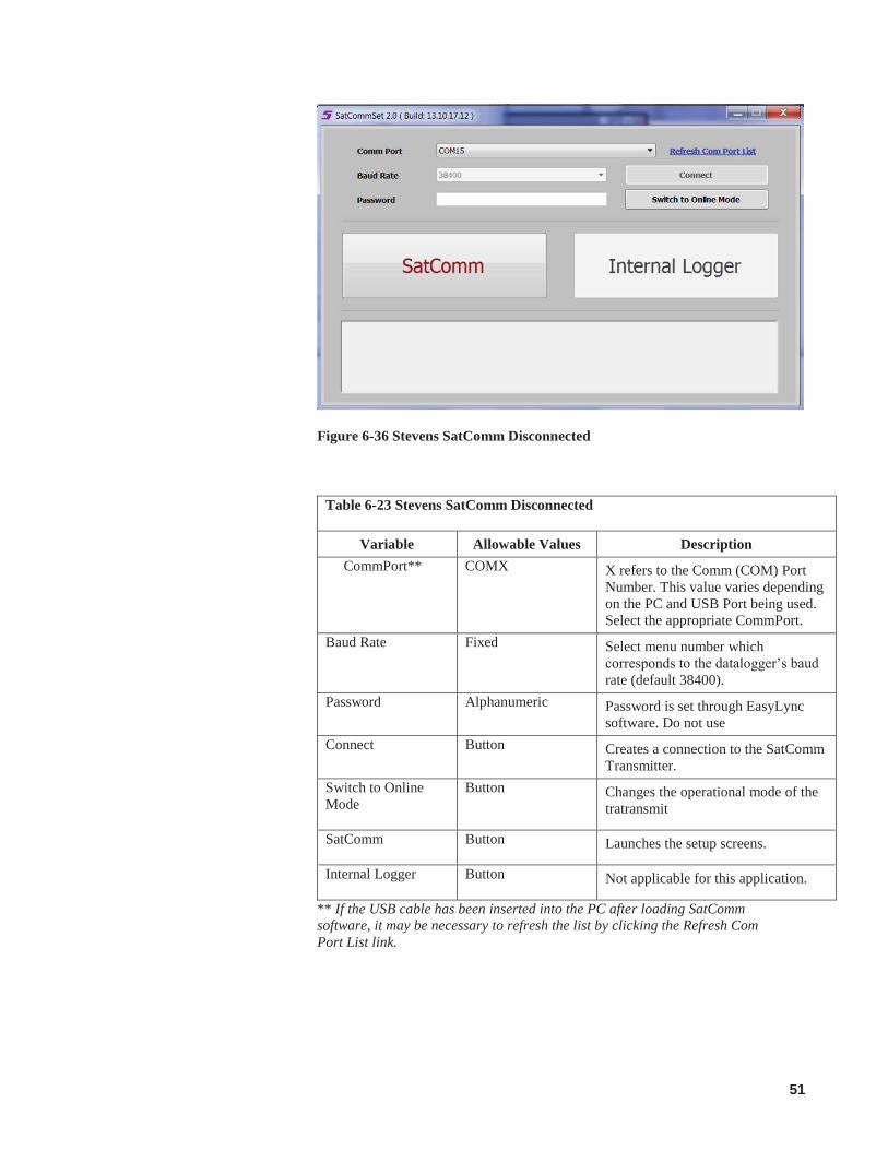
51
Figure 6-36 Stevens SatComm Disconnected
Table 6-23 Stevens SatComm Disconnected
Variable Allowable Values Description CommPort** COMX X refers to the Comm (COM) Port
Number. This value varies depending on the PC and USB Port being used. Select the appropriate CommPort.
Baud Rate Fixed Select menu number which corresponds to the datalogger’s baud rate (default 38400).
Password Alphanumeric Password is set through EasyLync software. Do not use
Connect Button Creates a connection to the SatComm Transmitter.
Switch to Online Mode
Button Changes the operational mode of the tratransmit
SatComm Button Launches the setup screens.
Internal Logger Button Not applicable for this application.
** If the USB cable has been inserted into the PC after loading SatComm software, it may be necessary to refresh the list by clicking the Refresh Com Port List link.
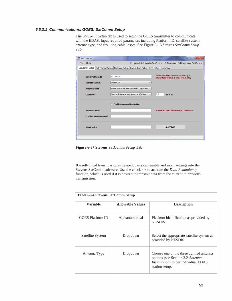
52
6.5.3.1 Communications: GOES: SatComm Setup The SatComm Setup tab is used to setup the GOES transmitter to communicate with the EDAS. Input required parameters including Platform ID, satellite system, antenna type, and resulting cable losses. See Figure 6-16 Stevens SatComm Setup Tab.
Figure 6-37 Stevens SatComm Setup Tab
If a self-timed transmission is desired, users can enable and input settings into the Stevens SatComm software. Use the checkbox to activate the Data Redundancy function, which is used if it is desired to transmit data from the current to previous transmission.
Table 6-24 Stevens SatComm Setup
Variable Allowable Values Description
GOES Platform ID
Alphanumerical
Platform identification as provided by NESDIS.
Satellite System
Dropdown
Select the appropriate satellite system as provided by NESDIS.
Antenna Type
Dropdown
Choose one of the three defined antenna options (see Section 3.2 Antenna Installation) as per individual EDAS station setup.
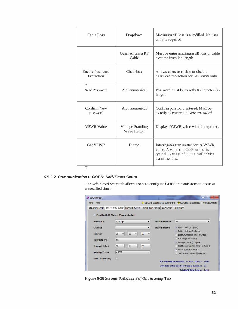
53
*
T
6.5.3.2 Communications: GOES: Self-Times Setup The Self-Timed Setup tab allows users to configure GOES transmissions to occur at a specified time.
Figure 6-38 Stevens SatComm Self-Timed Setup Tab
Cable Loss
Dropdown
Maximum dB loss is autofilled. No user entry is required.
Other Antenna RF
Cable
Must be enter maximum dB loss of cable over the installed length.
Enable Password
Protection
Checkbox
Allows users to enable or disable password protection for SatComm only.
New Password
Alphanumerical
Password must be exactly 8 characters in length.
Confirm New
Password
Alphanumerical
Confirm password entered. Must be exactly as entered in New Password.
VSWR Value
Voltage Standing
Wave Ration
Displays VSWR value when intergrated.
Get VSWR
Button
Interrogates transmitter for its VSWR value. A value of 002:00 or less is typical. A value of 005.00 will inhibit transmissions.
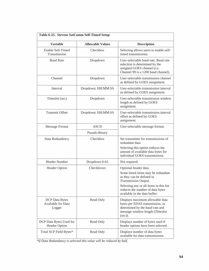
54
Table 6-25. Stevens SatComm Self-Timed Setup
Variable Allowable Values Description
Enable Self-Timed Transmission
Checkbox Selecting allows users to enable self-timed transmissions.
Baud Rate Dropdown User-selectable baud rate. Baud rate selection is determined by the assigned GOES channel (i.e. Channel 99 is a 1200 baud channel).
Channel Dropdown User-selectable transmission channel as defined by GOES assignment.
Interval Dropdown: HH:MM:SS User-selectable transmission interval as defined by GOES assignment.
Timeslot (sec) Dropdown User-selectable transmission window length as defined by GOES assignment.
Transmit Offset Dropdown: HH:MM:SS User-selectable transmission interval offset as defined by GOES assignment.
Message Format ASCII User-selectable message format.
Pseudo-Binary
Data Redundency Checkbox Set transmitter for transmissions of redundant data. Selecting this option reduces the amount of available data bytes for individual GOES transmissions.
Header Number Dropdown 0-63 Not required.
Header Option
Checkboxes Optional header data. Some listed items may be redundant as they can be defined in Transmission Output. Selecting any or all items in this list reduces the number of data bytes available in the data buffer.
DCP Data Bytes Avaliable for Data
Logger
Read Only Displays maximum allowable data bytes per EDAS transmission, as determined by the baud rate and message window length (Timeslot (sec)).
DCP Data Bytes Used for Header Option
Read Only Displays number of bytes used if header options have been selected.
Total SCP Field Bytes* Read Only Displays number of data bytes available for data transmissions.
*If Data Redundancy is selected this value will be reduced by half.
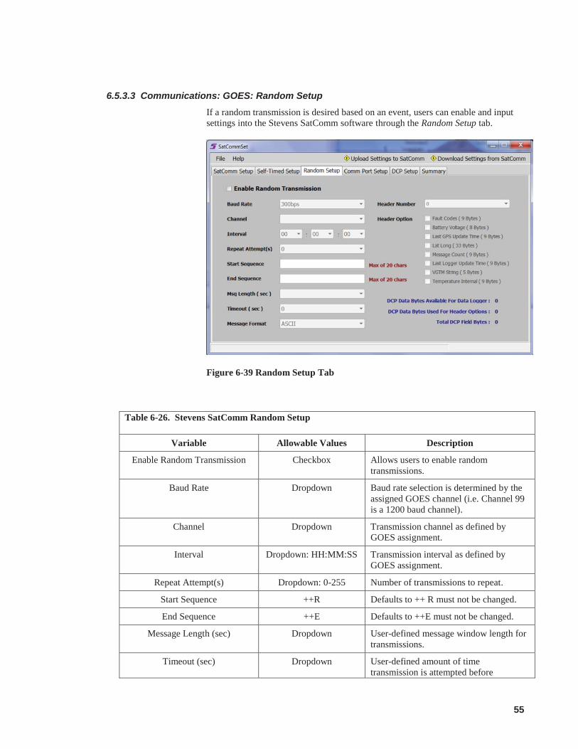
55
6.5.3.3 Communications: GOES: Random Setup If a random transmission is desired based on an event, users can enable and input settings into the Stevens SatComm software through the Random Setup tab.
Figure 6-39 Random Setup Tab
Table 6-26. Stevens SatComm Random Setup
Variable Allowable Values Description
Enable Random Transmission Checkbox Allows users to enable random transmissions.
Baud Rate Dropdown Baud rate selection is determined by the assigned GOES channel (i.e. Channel 99 is a 1200 baud channel).
Channel Dropdown Transmission channel as defined by GOES assignment.
Interval Dropdown: HH:MM:SS Transmission interval as defined by GOES assignment.
Repeat Attempt(s) Dropdown: 0-255 Number of transmissions to repeat.
Start Sequence ++R Defaults to ++ R must not be changed.
End Sequence ++E Defaults to ++E must not be changed.
Message Length (sec) Dropdown User-defined message window length for transmissions.
Timeout (sec) Dropdown User-defined amount of time transmission is attempted before
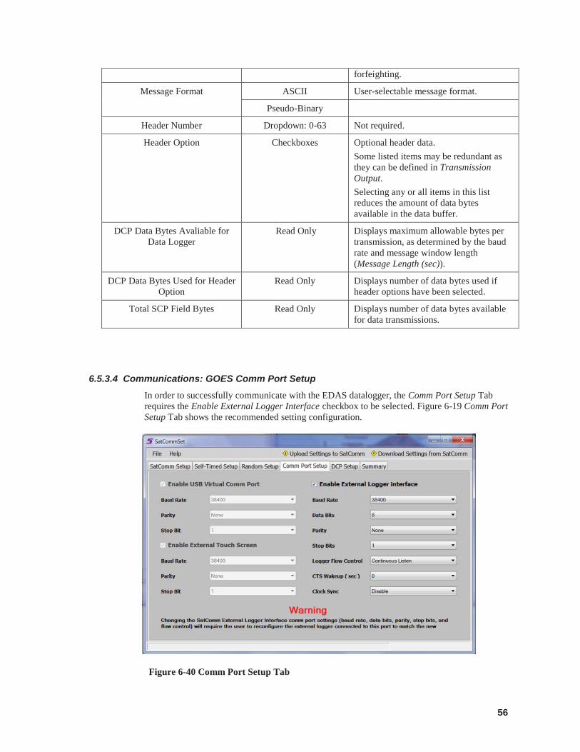
56
forfeighting.
Message Format ASCII User-selectable message format.
Pseudo-Binary
Header Number Dropdown: 0-63 Not required.
Header Option Checkboxes Optional header data. Some listed items may be redundant as they can be defined in Transmission Output. Selecting any or all items in this list reduces the amount of data bytes available in the data buffer.
DCP Data Bytes Avaliable for Data Logger
Read Only Displays maximum allowable bytes per transmission, as determined by the baud rate and message window length (Message Length (sec)).
DCP Data Bytes Used for Header Option
Read Only Displays number of data bytes used if header options have been selected.
Total SCP Field Bytes Read Only Displays number of data bytes available for data transmissions.
6.5.3.4 Communications: GOES Comm Port Setup In order to successfully communicate with the EDAS datalogger, the Comm Port Setup Tab requires the Enable External Logger Interface checkbox to be selected. Figure 6-19 Comm Port Setup Tab shows the recommended setting configuration.
Figure 6-40 Comm Port Setup Tab
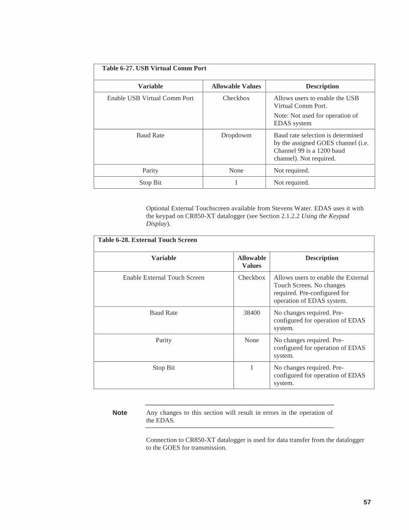
57
Table 6-27. USB Virtual Comm Port
Variable Allowable Values Description
Enable USB Virtual Comm Port Checkbox Allows users to enable the USB Virtual Comm Port. Note: Not used for operation of EDAS system
Baud Rate Dropdowm Baud rate selection is determined by the assigned GOES channel (i.e. Channel 99 is a 1200 baud channel). Not required.
Parity None Not required.
Stop Bit 1 Not required.
Optional External Touchscreen available from Stevens Water. EDAS uses it with the keypad on CR850-XT datalogger (see Section 2.1.2.2 Using the Keypad Display).
Table 6-28. External Touch Screen
Variable Allowable Values
Description
Enable External Touch Screen Checkbox Allows users to enable the External Touch Screen. No changes required. Pre-configured for operation of EDAS system.
Baud Rate 38400 No changes required. Pre-configured for operation of EDAS system.
Parity None No changes required. Pre-configured for operation of EDAS system.
Stop Bit 1 No changes required. Pre-configured for operation of EDAS system.
Any changes to this section will result in errors in the operation of the EDAS.
Connection to CR850-XT datalogger is used for data transfer from the datalogger to the GOES for transmission.
Note
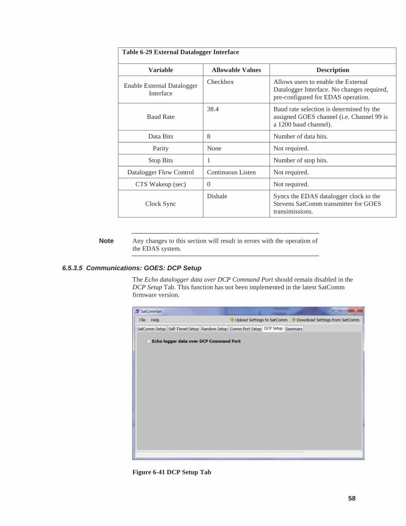
58
Table 6-29 External Datalogger Interface
Variable Allowable Values Description
Enable External Datalogger Interface
Checkbox Allows users to enable the External Datalogger Interface. No changes required, pre-configured for EDAS operation.
Baud Rate 38.4 Baud rate selection is determined by the
assigned GOES channel (i.e. Channel 99 is a 1200 baud channel).
Data Bits 8 Number of data bits.
Parity None Not required.
Stop Bits 1 Number of stop bits.
Datalogger Flow Control Continuous Listen Not required.
CTS Wakeup (sec) 0 Not required.
Clock Sync Disbale Syncs the EDAS datalogger clock to the
Stevens SatComm transmitter for GOES transimissions.
Any changes to this section will result in errors with the operation of the EDAS system.
6.5.3.5 Communications: GOES: DCP Setup The Echo datalogger data over DCP Command Port should remain disabled in the DCP Setup Tab. This function has not been implemented in the latest SatComm firmware version.
Figure 6-41 DCP Setup Tab
Note
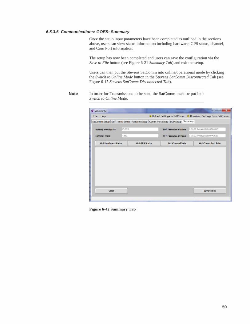
59
6.5.3.6 Communications: GOES: Summary Once the setup input parameters have been completed as outlined in the sections above, users can view status information including hardware, GPS status, channel, and Com Port information.
The setup has now been completed and users can save the configuration via the Save to File button (see Figure 6-21 Summary Tab) and exit the setup.
Users can then put the Stevens SatComm into online/operational mode by clicking the Switch to Online Mode button in the Stevens SatComm Disconnected Tab (see Figure 6-15 Stevens SatComm Disconnected Tab).
In order for Transmissions to be sent, the SatComm must be put into Switch to Online Mode.
Figure 6-42 Summary Tab
Note
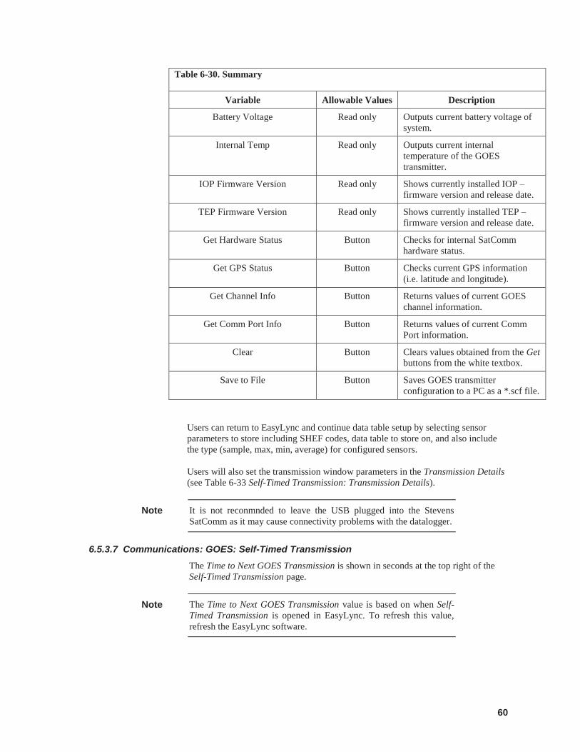
60
Table 6-30. Summary
Variable Allowable Values Description
Battery Voltage Read only Outputs current battery voltage of system.
Internal Temp Read only Outputs current internal temperature of the GOES transmitter.
IOP Firmware Version Read only Shows currently installed IOP – firmware version and release date.
TEP Firmware Version Read only Shows currently installed TEP – firmware version and release date.
Get Hardware Status Button Checks for internal SatComm hardware status.
Get GPS Status Button Checks current GPS information (i.e. latitude and longitude).
Get Channel Info Button Returns values of current GOES channel information.
Get Comm Port Info Button Returns values of current Comm Port information.
Clear Button Clears values obtained from the Get buttons from the white textbox.
Save to File Button Saves GOES transmitter configuration to a PC as a *.scf file.
Users can return to EasyLync and continue data table setup by selecting sensor parameters to store including SHEF codes, data table to store on, and also include the type (sample, max, min, average) for configured sensors.
Users will also set the transmission window parameters in the Transmission Details (see Table 6-33 Self-Timed Transmission: Transmission Details).
It is not reconmnded to leave the USB plugged into the Stevens SatComm as it may cause connectivity problems with the datalogger.
6.5.3.7 Communications: GOES: Self-Timed Transmission The Time to Next GOES Transmission is shown in seconds at the top right of the Self-Timed Transmission page.
The Time to Next GOES Transmission value is based on when Self-Timed Transmission is opened in EasyLync. To refresh this value, refresh the EasyLync software.
Note
Note
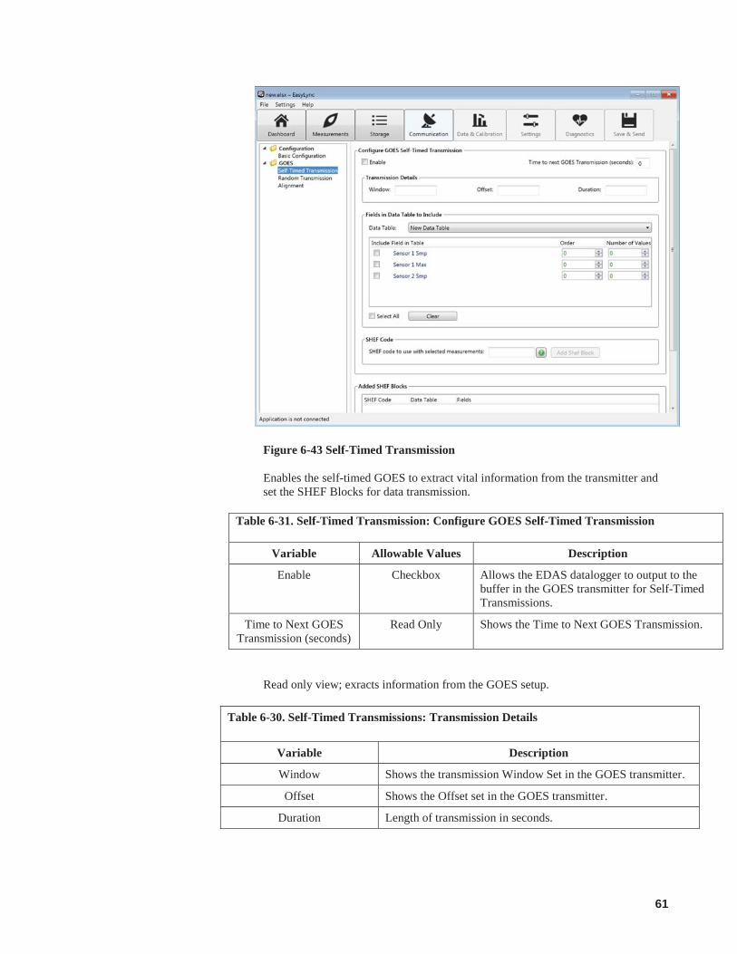
61
Figure 6-43 Self-Timed Transmission
Enables the self-timed GOES to extract vital information from the transmitter and set the SHEF Blocks for data transmission.
Table 6-31. Self-Timed Transmission: Configure GOES Self-Timed Transmission
Variable Allowable Values Description
Enable Checkbox Allows the EDAS datalogger to output to the buffer in the GOES transmitter for Self-Timed Transmissions.
Time to Next GOES Transmission (seconds)
Read Only Shows the Time to Next GOES Transmission.
Read only view; exracts information from the GOES setup.
Table 6-30. Self-Timed Transmissions: Transmission Details
Variable Description
Window Shows the transmission Window Set in the GOES transmitter.
Offset Shows the Offset set in the GOES transmitter.
Duration Length of transmission in seconds.
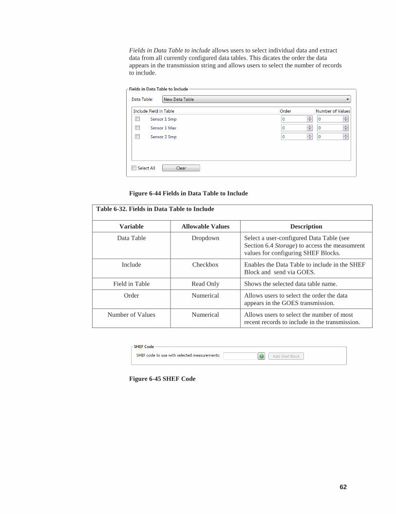
62
Fields in Data Table to include allows users to select individual data and extract data from all currently configured data tables. This dicates the order the data appears in the transmission string and allows users to select the number of records to include.
Figure 6-44 Fields in Data Table to Include
Table 6-32. Fields in Data Table to Include
Variable Allowable Values Description
Data Table Dropdown Select a user-configured Data Table (see Section 6.4 Storage) to access the measumrent values for configuring SHEF Blocks.
Include Checkbox Enables the Data Table to include in the SHEF Block and send via GOES.
Field in Table Read Only Shows the selected data table name.
Order Numerical Allows users to select the order the data appears in the GOES transmission.
Number of Values Numerical Allows users to select the number of most recent records to include in the transmission.
Figure 6-45 SHEF Code
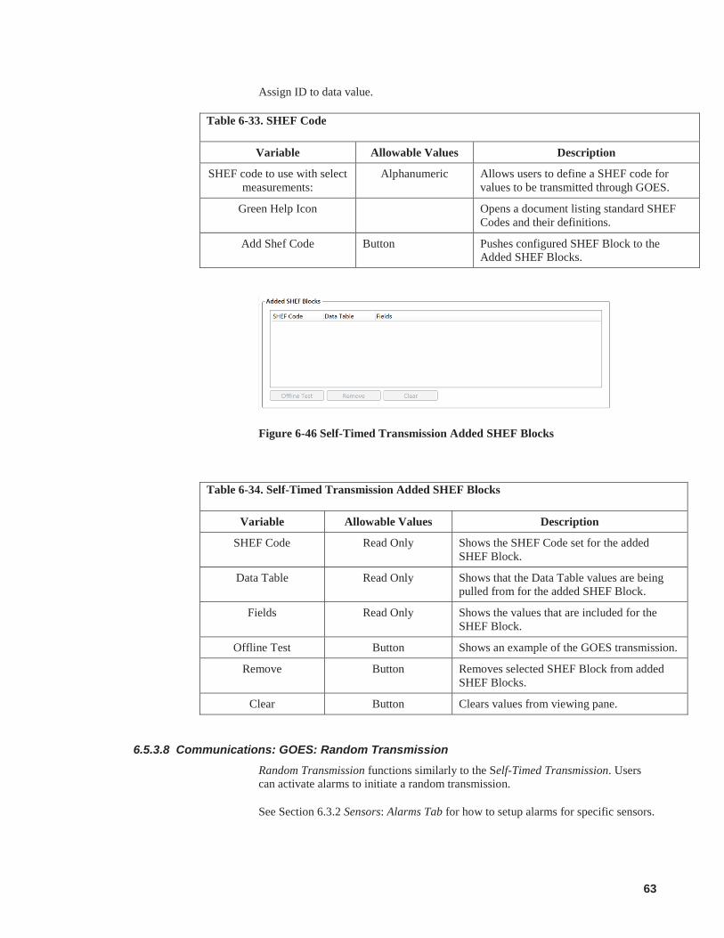
63
Assign ID to data value.
Table 6-33. SHEF Code
Variable Allowable Values Description
SHEF code to use with select measurements:
Alphanumeric Allows users to define a SHEF code for values to be transmitted through GOES.
Green Help Icon Opens a document listing standard SHEF Codes and their definitions.
Add Shef Code Button Pushes configured SHEF Block to the Added SHEF Blocks.
Figure 6-46 Self-Timed Transmission Added SHEF Blocks
Table 6-34. Self-Timed Transmission Added SHEF Blocks
Variable Allowable Values Description
SHEF Code Read Only Shows the SHEF Code set for the added SHEF Block.
Data Table Read Only Shows that the Data Table values are being pulled from for the added SHEF Block.
Fields Read Only Shows the values that are included for the SHEF Block.
Offline Test Button Shows an example of the GOES transmission.
Remove Button Removes selected SHEF Block from added SHEF Blocks.
Clear Button Clears values from viewing pane.
6.5.3.8 Communications: GOES: Random Transmission Random Transmission functions similarly to the Self-Timed Transmission. Users can activate alarms to initiate a random transmission.
See Section 6.3.2 Sensors: Alarms Tab for how to setup alarms for specific sensors.
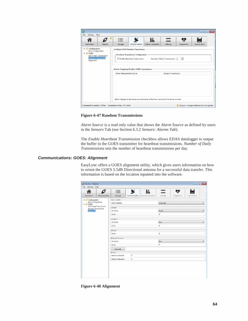
64
Figure 6-47 Random Transmissions
Alarm Source is a read only value that shows the Alarm Source as defined by users in the Sensors Tab (see Section 6.3.2 Sensors: Alarms Tab).
The Enable Heartbeat Transmission checkbox allows EDAS datalogger to output the buffer in the GOES transmitter for heartbeat transmissions. Number of Daily Transmissions sets the number of heartbeat transmissions per day.
Communications: GOES: Alignment EasyLync offers a GOES alignment utility, which gives users information on how to orient the GOES 5.5dB Directional antenna for a successful data transfer. This information is based on the location inputted into the software.
Figure 6-48 Alignment
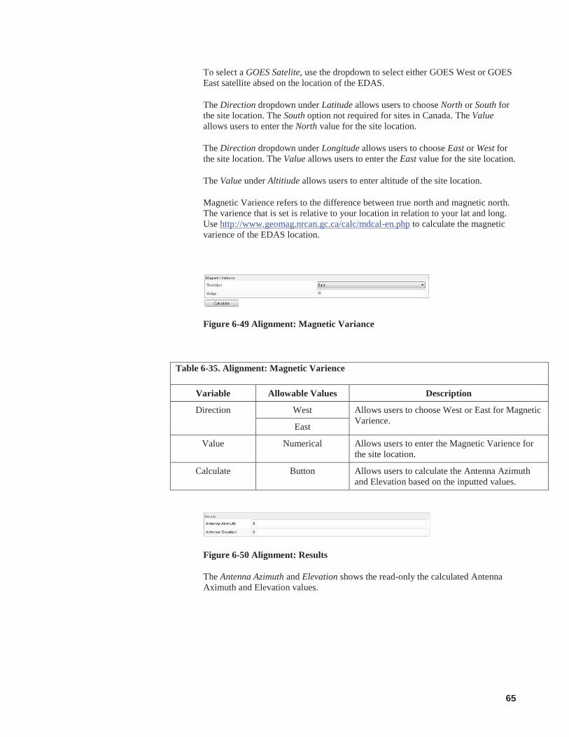
65
To select a GOES Satelite, use the dropdown to select either GOES West or GOES East satellite absed on the location of the EDAS.
The Direction dropdown under Latitude allows users to choose North or South for the site location. The South option not required for sites in Canada. The Value allows users to enter the North value for the site location.
The Direction dropdown under Longitude allows users to choose East or West for the site location. The Value allows users to enter the East value for the site location.
The Value under Altitiude allows users to enter altitude of the site location.
Magnetic Varience refers to the difference between true north and magnetic north. The varience that is set is relative to your location in relation to your lat and long. Use http://www.geomag.nrcan.gc.ca/calc/mdcal-en.php to calculate the magnetic varience of the EDAS location.
Figure 6-49 Alignment: Magnetic Variance
Table 6-35. Alignment: Magnetic Varience
Variable Allowable Values Description
Direction West Allows users to choose West or East for Magnetic Varience. East
Value Numerical Allows users to enter the Magnetic Varience for the site location.
Calculate Button Allows users to calculate the Antenna Azimuth and Elevation based on the inputted values.
Figure 6-50 Alignment: Results
The Antenna Azimuth and Elevation shows the read-only the calculated Antenna Aximuth and Elevation values.

66
6.6 Data & Calibration The Data & Calibration tabs are designed as a workflow: monitor, calibrate, collect, and visualize incoming data. The workflow tabs are:
Storage Monitor Live Reading and Calibration Data Collection Graph
Data and Calibration will not work in Offline – Terminal mode.
6.6.1 Data & Calibration: Table Monitor Tab From the Table Monitor tab, data collected from the datalogger is viewed. Data is pulled directly from the datalogger at a minimum of every 10 seconds (default).
Figure 6-51 Data & Calibration: Table Monitor
Real Time Monitoring allows users to view the latest measured or stored values from the EDAS datalogger.
Note
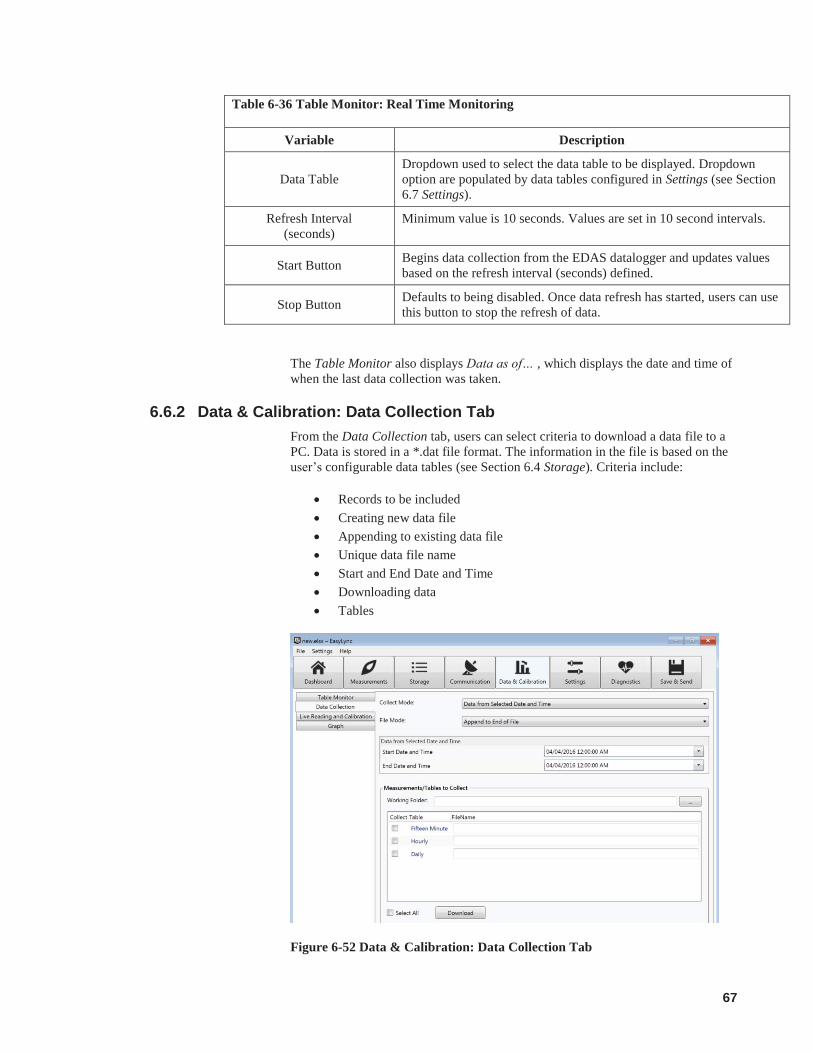
67
Table 6-36 Table Monitor: Real Time Monitoring
Variable Description
Data Table Dropdown used to select the data table to be displayed. Dropdown option are populated by data tables configured in Settings (see Section 6.7 Settings).
Refresh Interval (seconds)
Minimum value is 10 seconds. Values are set in 10 second intervals.
Start Button Begins data collection from the EDAS datalogger and updates values based on the refresh interval (seconds) defined.
Stop Button Defaults to being disabled. Once data refresh has started, users can use this button to stop the refresh of data.
The Table Monitor also displays Data as of… , which displays the date and time of when the last data collection was taken.
6.6.2 Data & Calibration: Data Collection Tab From the Data Collection tab, users can select criteria to download a data file to a PC. Data is stored in a *.dat file format. The information in the file is based on the user’s configurable data tables (see Section 6.4 Storage). Criteria include:
Records to be included Creating new data file Appending to existing data file Unique data file name Start and End Date and Time Downloading data Tables
Figure 6-52 Data & Calibration: Data Collection Tab

68
The Data Collection Tab allows users to collect stored data using various collection options set in Sensors (see Section 6.3.1 Sensors: Details Tab).
Table 6-37 Data Collection
Variable Allowable Values Description
Collect Mode
Allows users to choose how much data to collect from the EDAS.
Newest Number of Records
Retrieve the number of records specified in the Starting Record Number going back from the last record collected. Additional options appear when selected ( see Table XXX Starting Record Information).
Specific Records Retrieve a specified number of records beginning with the Starting Record Number as specified in the Starting Record Field. Additional options appear when selected (see Table XXX Starting Record Information).
All Data Retrieves all available data from selected tables in the EDAS datalogger.
Data from Selected Date and Time
Uses the user-selected start and end times and dates to obtain the data from the EDAS to be stored between the selected times. If the EDAS does not have data for the specified time range, a blank file will be created. Additional options will appear when selected (see Table XXXX Data from Selected Date and Time).
File Mode
File Mode is used to choose whether the collection data should be appended to an existing file, overwrite an existing file, or create a new file. If Create New File is selected and the named file already exists, a new file will be created with the file name and a sequence number will be added to it.
Append to End of File Adds the new data to the end of the existing data file.
Overwrite Existing File
Replaces the current file with a newly created data file.
Create a New File Renames the existing file with a .*bak extension and stores new data with the specified file name. Subsequent *.bak files will be named *.bak1, *.bak2, etc. The most recent *.bak file will have the highest number.
Starting Record Information, as it appears when Newest Number of Records is selected from Collect Mode (see Table 6-36 Data Colleciton). Number of Records is a numerical value which dictates the number of records to be collected.
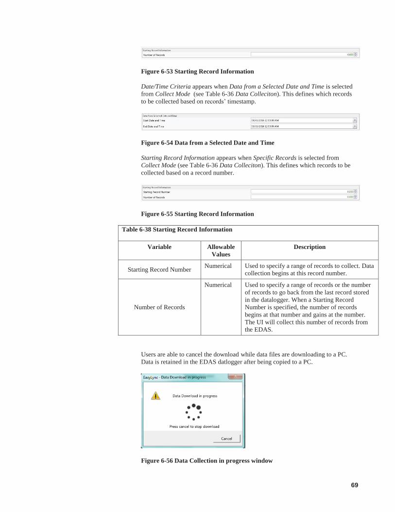
69
Figure 6-53 Starting Record Information
Date/Time Criteria appears when Data from a Selected Date and Time is selected from Collect Mode (see Table 6-36 Data Colleciton). This defines which records to be collected based on records’ timestamp.
Figure 6-54 Data from a Selected Date and Time
Starting Record Information appears when Specific Records is selected from Collect Mode (see Table 6-36 Data Colleciton). This defines which records to be collected based on a record number.
Figure 6-55 Starting Record Information
Table 6-38 Starting Record Information
Variable Allowable Values
Description
Starting Record Number Numerical Used to specify a range of records to collect. Data collection begins at this record number.
Number of Records
Numerical Used to specify a range of records or the number of records to go back from the last record stored in the datalogger. When a Starting Record Number is specified, the number of records begins at that number and gains at the number. The UI will collect this number of records from the EDAS.
Users are able to cancel the download while data files are downloading to a PC. Data is retained in the EDAS datlogger after being copied to a PC.
Figure 6-56 Data Collection in progress window
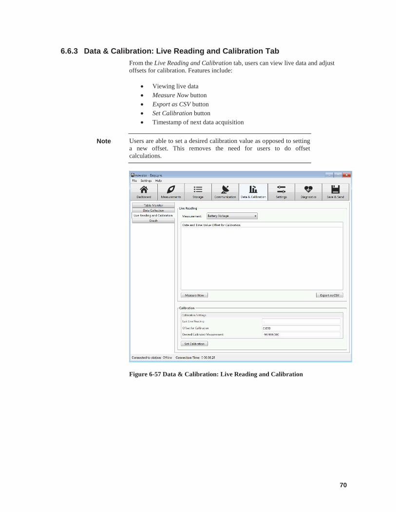
70
6.6.3 Data & Calibration: Live Reading and Calibration Tab From the Live Reading and Calibration tab, users can view live data and adjust offsets for calibration. Features include:
Viewing live data Measure Now button Export as CSV button Set Calibration button Timestamp of next data acquisition
Users are able to set a desired calibration value as opposed to setting a new offset. This removes the need for users to do offset calculations.
Figure 6-57 Data & Calibration: Live Reading and Calibration
Note
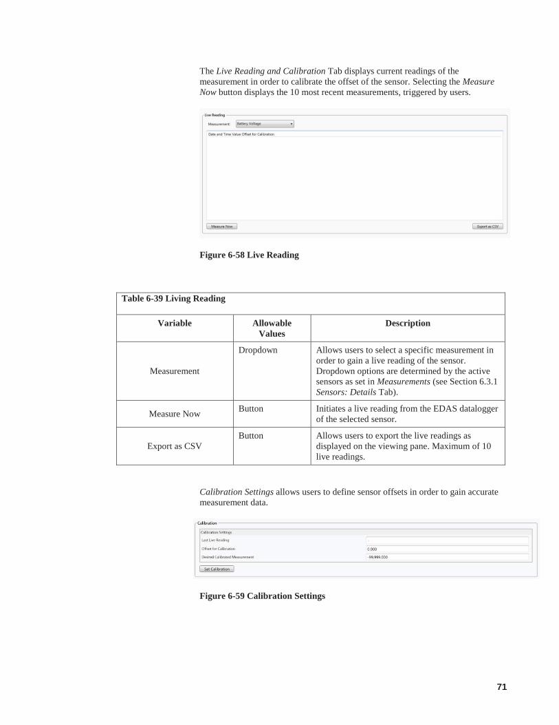
71
The Live Reading and Calibration Tab displays current readings of the measurement in order to calibrate the offset of the sensor. Selecting the Measure Now button displays the 10 most recent measurements, triggered by users.
Figure 6-58 Live Reading
Table 6-39 Living Reading
Variable Allowable Values
Description
Measurement
Dropdown Allows users to select a specific measurement in order to gain a live reading of the sensor. Dropdown options are determined by the active sensors as set in Measurements (see Section 6.3.1 Sensors: Details Tab).
Measure Now Button Initiates a live reading from the EDAS datalogger of the selected sensor.
Export as CSV Button Allows users to export the live readings as
displayed on the viewing pane. Maximum of 10 live readings.
Calibration Settings allows users to define sensor offsets in order to gain accurate measurement data.
Figure 6-59 Calibration Settings
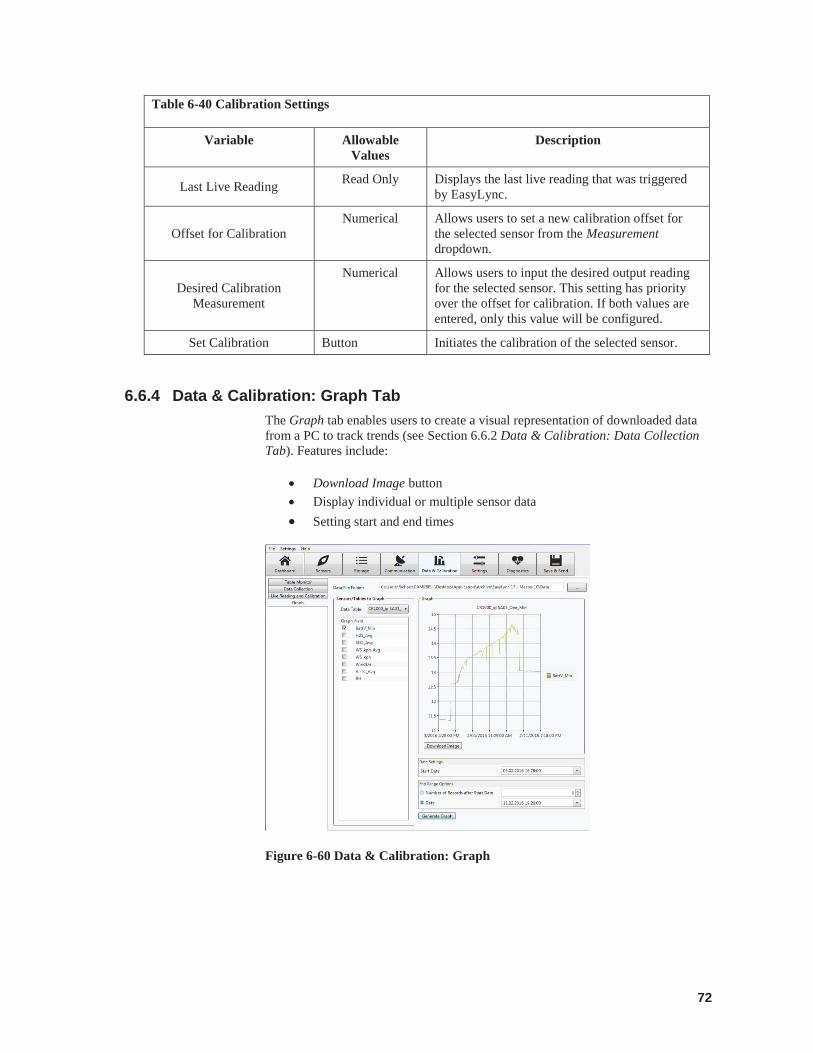
72
Table 6-40 Calibration Settings
Variable Allowable Values
Description
Last Live Reading Read Only Displays the last live reading that was triggered by EasyLync.
Offset for Calibration Numerical Allows users to set a new calibration offset for
the selected sensor from the Measurement dropdown.
Desired Calibration Measurement
Numerical Allows users to input the desired output reading for the selected sensor. This setting has priority over the offset for calibration. If both values are entered, only this value will be configured.
Set Calibration Button Initiates the calibration of the selected sensor.
6.6.4 Data & Calibration: Graph Tab The Graph tab enables users to create a visual representation of downloaded data from a PC to track trends (see Section 6.6.2 Data & Calibration: Data Collection Tab). Features include:
Download Image button Display individual or multiple sensor data Setting start and end times
Figure 6-60 Data & Calibration: Graph
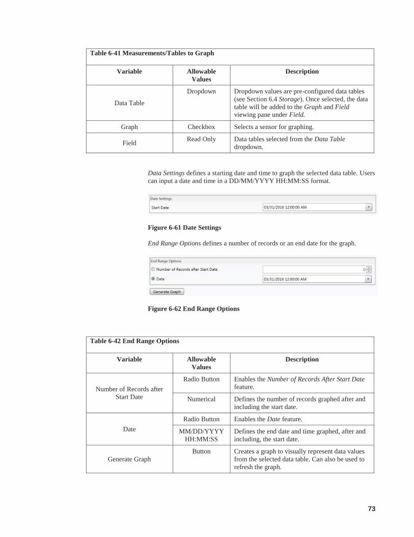
73
Table 6-41 Measurements/Tables to Graph
Variable Allowable Values
Description
Data Table
Dropdown Dropdown values are pre-configured data tables (see Section 6.4 Storage). Once selected, the data table will be added to the Graph and Field viewing pane under Field.
Graph Checkbox Selects a sensor for graphing.
Field Read Only Data tables selected from the Data Table dropdown.
Data Settings defines a starting date and time to graph the selected data table. Users can input a date and time in a DD/MM/YYYY HH:MM:SS format.
Figure 6-61 Date Settings
End Range Options defines a number of records or an end date for the graph.
Figure 6-62 End Range Options
Table 6-42 End Range Options
Variable Allowable Values
Description
Number of Records after Start Date
Radio Button Enables the Number of Records After Start Date feature.
Numerical Defines the number of records graphed after and including the start date.
Date Radio Button Enables the Date feature.
MM/DD/YYYY HH:MM:SS
Defines the end date and time graphed, after and including, the start date.
Generate Graph Button Creates a graph to visually represent data values
from the selected data table. Can also be used to refresh the graph.
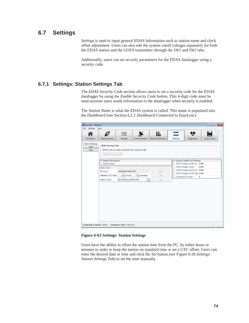
74
6.7 Settings Settings is used to input general EDAS information such as station name and clock offset adjustment. Users can also edit the system cutoff voltages separately for both the EDAS station and the GOES transmitter through the SW1 and SW2 tabs.
Additionally, users can set security parameters for the EDAS datalogger using a security code.
6.7.1 Settings: Station Settings Tab The EDAS Security Code section allows users to set a security code for the EDAS datalogger by using the Enable Security Code button. This 4-digit code must be used anytime users sends information to the datalogger when seciurty is enabled.
The Station Name is what the EDAS system is called. This name is populated into the Dashboard (see Section 6.2.2 Dashboard:Connected to EasyLync).
Figure 6-63 Settings: Station Settings
Users have the ability to offset the station time from the PC, by either hours or minutes in order to keep the station on standard time or set a UTC offset. Users can enter the desired date or time and click the Set button (see Figure 6-26 Settings: Station Settings Tab) to set the time manually.
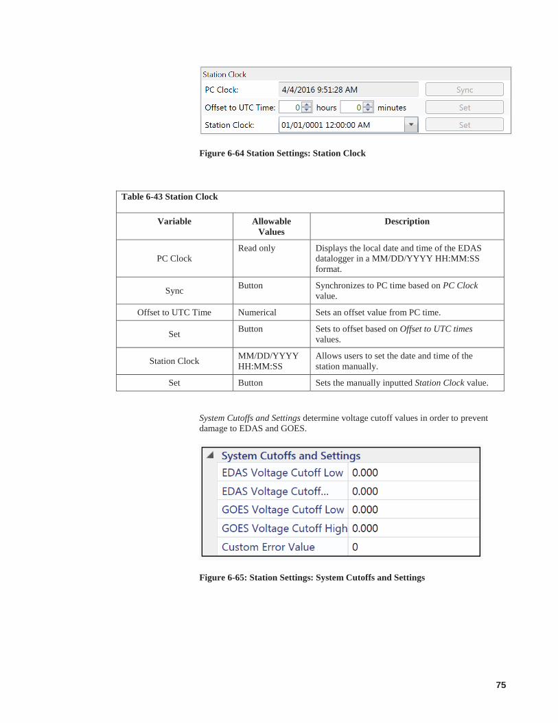
75
Figure 6-64 Station Settings: Station Clock
Table 6-43 Station Clock
Variable Allowable Values
Description
PC Clock Read only Displays the local date and time of the EDAS
datalogger in a MM/DD/YYYY HH:MM:SS format.
Sync Button Synchronizes to PC time based on PC Clock value.
Offset to UTC Time Numerical Sets an offset value from PC time.
Set Button Sets to offset based on Offset to UTC times values.
Station Clock MM/DD/YYYY HH:MM:SS
Allows users to set the date and time of the station manually.
Set Button Sets the manually inputted Station Clock value.
System Cutoffs and Settings determine voltage cutoff values in order to prevent damage to EDAS and GOES.
Figure 6-65: Station Settings: System Cutoffs and Settings
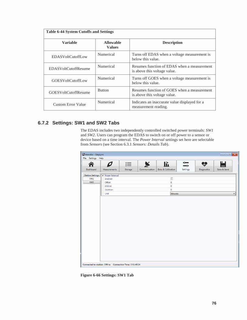
76
Table 6-44 System Cutoffs and Settings
Variable Allowable Values
Description
EDASVoltCutoffLow Numerical Turns off EDAS when a voltage measurement is below this value.
EDASVoltCutoffResume Numerical Resumes function of EDAS when a measurement is above this voltage value.
GOESVoltCutoffLow Numerical Turns off GOES when a voltage measurement is below this value.
GOESVoltCutoffResume Button Resumes function of GOES when a measurement is above this voltage value.
Custom Error Value Numerical Indicates an inaccurate value displayed for a measurement reading.
6.7.2 Settings: SW1 and SW2 Tabs The EDAS includes two independently controlled switched power terminals: SW1 and SW2. Users can program the EDAS to switch on or off power to a sensor or device based on a time interval. The Power Interval settings set here are selectable from Sensors (see Section 6.3.1 Sensors: Details Tab).
Figure 6-66 Settings: SW1 Tab
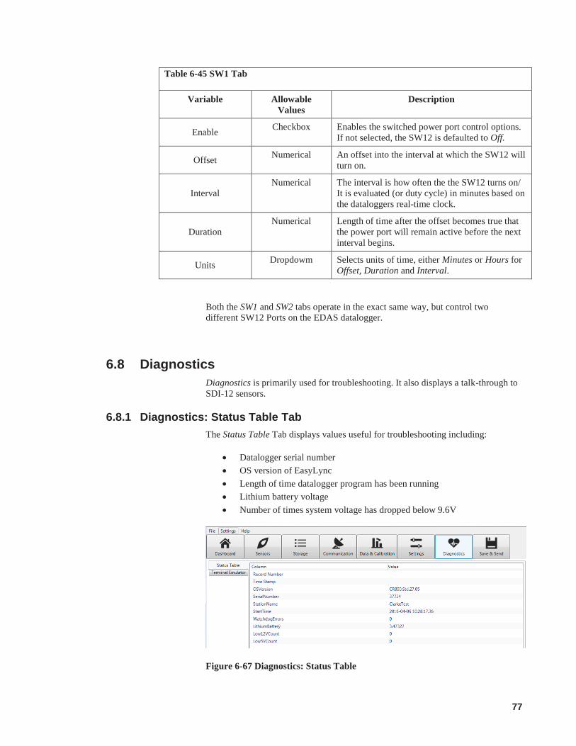
77
Table 6-45 SW1 Tab
Variable Allowable Values
Description
Enable Checkbox Enables the switched power port control options. If not selected, the SW12 is defaulted to Off.
Offset Numerical An offset into the interval at which the SW12 will turn on.
Interval Numerical The interval is how often the the SW12 turns on/
It is evaluated (or duty cycle) in minutes based on the dataloggers real-time clock.
Duration Numerical Length of time after the offset becomes true that
the power port will remain active before the next interval begins.
Units Dropdowm Selects units of time, either Minutes or Hours for Offset, Duration and Interval.
Both the SW1 and SW2 tabs operate in the exact same way, but control two different SW12 Ports on the EDAS datalogger.
6.8 Diagnostics Diagnostics is primarily used for troubleshooting. It also displays a talk-through to SDI-12 sensors.
6.8.1 Diagnostics: Status Table Tab The Status Table Tab displays values useful for troubleshooting including:
Datalogger serial number OS version of EasyLync Length of time datalogger program has been running Lithium battery voltage Number of times system voltage has dropped below 9.6V
Figure 6-67 Diagnostics: Status Table
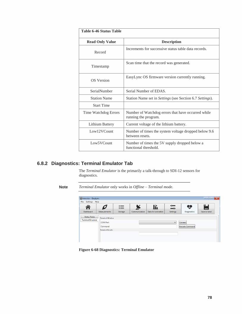
78
Table 6-46 Status Table
Read Only Value Description
Record Increments for successive status table data records.
Timestamp Scan time that the record was generated.
OS Version EasyLync OS firmware version currently running.
SerialNumber Serial Number of EDAS.
Station Name Station Name set in Settings (see Section 6.7 Settings).
Start Time
Time Watchdog Errors Number of Watchdog errors that have occurred while running the program.
Lithium Battery Current voltage of the lithium battery.
Low12VCount Number of times the system voltage dropped below 9.6 between resets.
Low5VCount Number of times the 5V supply dropped below a functional threshold.
6.8.2 Diagnostics: Terminal Emulator Tab The Terminal Emulator is the primarily a talk-through to SDI-12 sensors for diagnostics.
Terminal Emulator only works in Offline – Terminal mode.
Figure 6-68 Diagnostics: Terminal Emulator
Note

79
Table 6-47 Terminal Emulator
Variable Allowable Values
Description
Com Port
Dropdown Allows users to select Com Port available from the PC. Operates the same way as the Serial (see Table 6-4 Serial/Direct Connection Configuration).
Connect Button Establishes a connection.
Command Alphanumeric SDI-12 command (i.e. ?! for address query).
Terminal Results Read Only Output value.
6.9 Save & Send Save & Send enables users to save a settings file to the Working Folder (see Section 6.7 Settings) and simultaneously send this configuration data to an EDAS datalogger.
Save & Send includes an error log to indicate any reasons for failed transmissions (see Figure 6-33 Save & Send: Displayed Error). Progress indicators show the status of sending any configuration files to the EDAS datalogger. Should an error occur during upload, previous configuration and data will be retained.
Any changes to the datalogger configuration or sensors alert EasyLync resulting in the toolbar options causing the yellow warning icon to appear. This indicates the data inputted into EasyLync must be saved and sent.
Figure 6-69 Save & Send
Note

80
TABLE 6-56. Action
Variable Allowable Values
Description
Save to PC Button Saves a settings file on the PC. This can be obtained through EasyLync using the File dropdown and selecting Open. The file is saved as a *.elsx extension.
Save and Send to EDAS
Button Saves a setting file on the PC and sends an updateto the EDAS datalogger based on EasyLync configuration.
The EDAS provides a warning if any chages to the datalogger will result in a loss of data (see Figure 6-73 Save & Send: Confirm Send Pop-up).
Figure 6-70 Save & Send: Confirm Send Pop-up
In the Save and Send Activities area, there are green and red progress indicators, which indicates the status of the EDAS datalogger program creation or update. Red indicates there was an error. Information on any errors that have occured are displayed in the Error Messages area. Green indicates the update has been sent successfully.
TABLE 6-57. Save and Send Activities
Variable Values Description
Save Settings Red or Green Status Indicates the file has been saved to the PC.
Building Dataogger Program
Red or Green Status Indicates the settings file has been successfully created.
Sending Files Red or Green Status Indicates file transfer to the EDAS has been completed.
Program Activated Red or Green Status Indicates the settings file is now running on the EDAS.
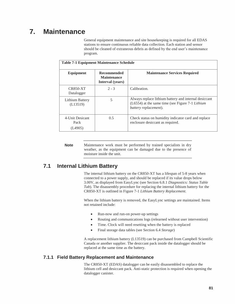
81
7. Maintenance General equipment maintenance and site housekeeping is required for all EDAS stations to ensure continuous reliable data collection. Each station and sensor should be cleaned of extraneous debris as defined by the end user’s maintenance program.
Table 7-1 Equipment Maintenance Schedule
Equipment Recommended Maintenance
Interval (years)
Maintenance Services Required
CR850-XT Datalogger
2 - 3 Calibration.
Lithium Battery (L13519)
5 Always replace lithium battery and internal desiccant (L6554) at the same time (see Figure 7-1 Lithium battery replacement).
4-Unit Desicant Pack
(L4905)
0.5 Check status on humidity indicator card and replace enclosure desiccant as required.
Maintenance work must be performed by trained specialists in dry weather, as the equipment can be damaged due to the presence of moisture inside the unit.
7.1 Internal Lithium Battery The internal lithium battery on the CR850-XT has a lifespan of 5-8 years when connected to a power supply, and should be replaced if its value drops below 3.00V, as displayed from EasyLync (see Section 6.8.1 Diagnostics: Status Table Tab). The disassembly procedure for replacing the internal lithium battery for the CR850-XT is outlined in Figure 7-1 Lithium Battery Replacement.
When the lithium battery is removed, the EasyLync settings are maintained. Items not retained include:
Run-now and run-on power-up settings Routing and communications logs (relearned without user intervention) Time. Clock will need resetting when the battery is replaced Final storage data tables (see Section 6.4 Storage)
A replacement lithium battery (L13519) can be purchased from Campbell Scientific Canada or another supplier. The desiccant pack inside the datalogger should be replaced at the same time as the battery.
7.1.1 Field Battery Replacement and Maintenance The CR850-XT (EDAS) datalogger can be easily disassembled to replace the lithium cell and desiccant pack. Anti-static protection is required when opening the datalogger canister.
Note
82
Tools required to replace battery and desiccant pack:
Replacement lithium battery (L13519) 2 replacement internal desiccant packs (L6554) 5/16 tin-walled socket driver #2 Phillips head screwdriver Small flathead screwdriver Tape Needle nose pliers (optional to hold nuts while unscrewing)
Follow Steps 1 through 6 as seen in Figure 7-1 Lithium battery replacement to replace the lithium battery.
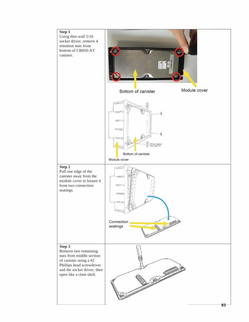
83
Step 1 Using thin-wall 5/16 socket driver, remove 4 retention nuts from bottom of CR850-XT canister.
Step 2 Pull one edge of the canister away from the module cover to loosen it from two connection seatings.
Step 3 Remove two remaining nuts from middle section of canister using a #2 Phillips head screwdriver and the socket driver, then open like a clam shell.
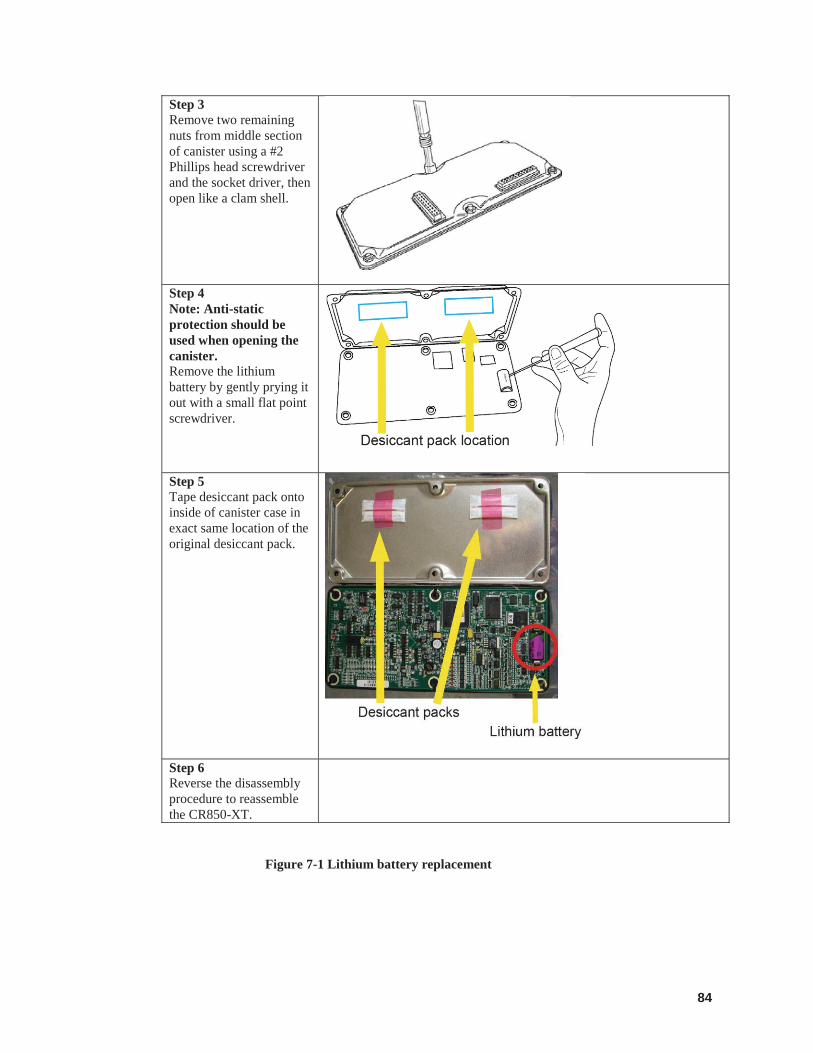
84
Step 3 Remove two remaining nuts from middle section of canister using a #2 Phillips head screwdriver and the socket driver, then open like a clam shell.
Step 4 Note: Anti-static protection should be used when opening the canister. Remove the lithium battery by gently prying it out with a small flat point screwdriver.
Step 5 Tape desiccant pack onto inside of canister case in exact same location of the original desiccant pack.
Step 6 Reverse the disassembly procedure to reassemble the CR850-XT.
Figure 7-1 Lithium battery replacement

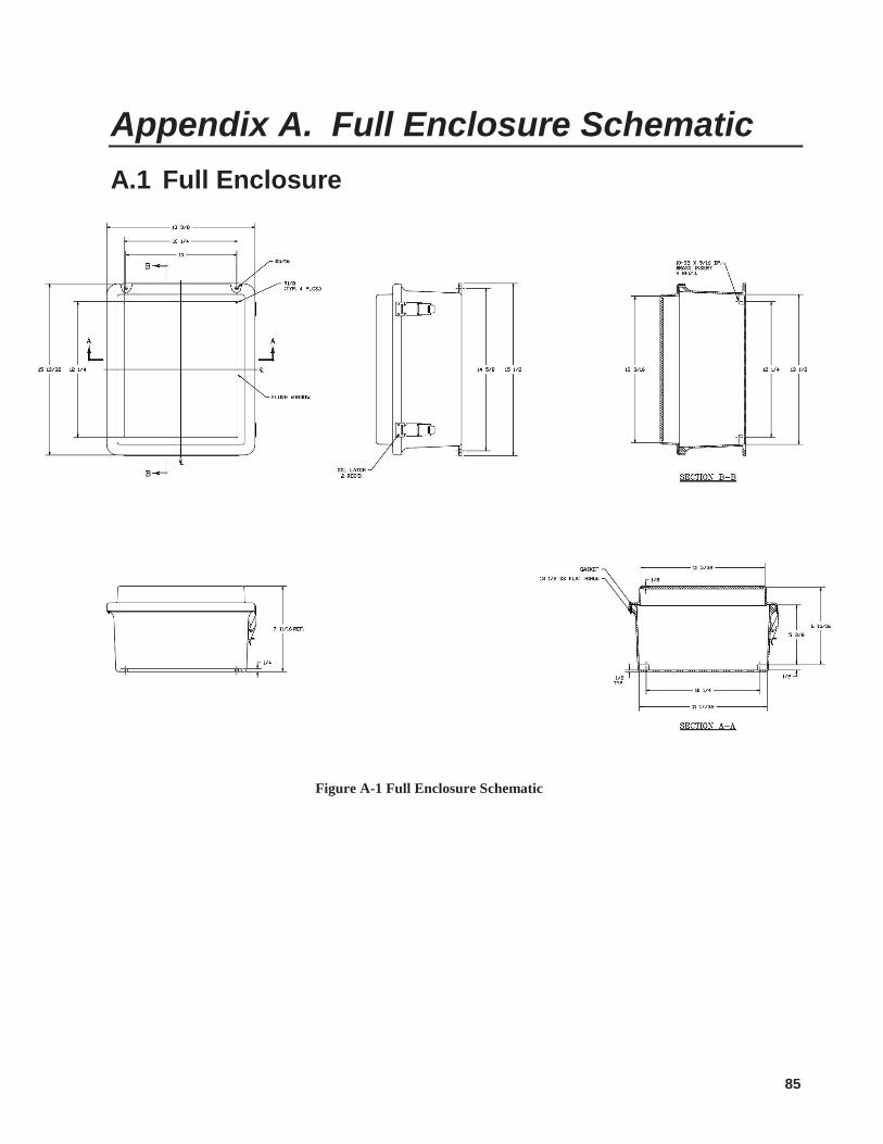
85
Appendix A. Full Enclosure Schematic A.1 Full Enclosure
Figure A-1 Full Enclosure Schematic

Campbell Scientific (Canada) Corp. | 14532 131 Avenue NW | Edmonton AB T5L 4X4 | 780.454.2505 | www.campbellsci.caAUSTRALIA | BRAZIL | CANADA | COSTA RICA | FRANCE | GERMANY | SOUTH AFRICA | SPAIN | UNITED KINGDOM | USA