Embed Size (px)
Citation preview

IEC/TS 60815-3Edition 1.0 2008-10
TECHNICAL SPECIFICATION
Selection and dimensioning of high-voltage insulators intended for use in polluted conditions – Part 3: Polymer insulators for a.c. systems
IEC
/TS
608
15-3
:200
8(E
) L
ICE
NSE
D T
O M
EC
ON
Lim
ited. - RA
NC
HI/B
AN
GA
LO
RE
FOR
INT
ER
NA
L U
SE A
T T
HIS L
OC
AT
ION
ON
LY
, SUPPL
IED
BY
BO
OK
SUPPL
Y B
UR
EA
U.

THIS PUBLICATION IS COPYRIGHT PROTECTED Copyright © 2008 IEC, Geneva, Switzerland All rights reserved. Unless otherwise specified, no part of this publication may be reproduced or utilized in any form or by any means, electronic or mechanical, including photocopying and microfilm, without permission in writing from either IEC or IEC's member National Committee in the country of the requester. If you have any questions about IEC copyright or have an enquiry about obtaining additional rights to this publication, please contact the address below or your local IEC member National Committee for further information. Droits de reproduction réservés. Sauf indication contraire, aucune partie de cette publication ne peut être reproduite ni utilisée sous quelque forme que ce soit et par aucun procédé, électronique ou mécanique, y compris la photocopie et les microfilms, sans l'accord écrit de la CEI ou du Comité national de la CEI du pays du demandeur. Si vous avez des questions sur le copyright de la CEI ou si vous désirez obtenir des droits supplémentaires sur cette publication, utilisez les coordonnées ci-après ou contactez le Comité national de la CEI de votre pays de résidence.
IEC Central Office 3, rue de Varembé CH-1211 Geneva 20 Switzerland Email: [email protected]: www.iec.ch
About IEC publications The technical content of IEC publications is kept under constant review by the IEC. Please make sure that you have the latest edition, a corrigenda or an amendment might have been published. Catalogue of IEC publications: www.iec.ch/searchpub
The IEC on-line Catalogue enables you to search by a variety of criteria (reference number, text, technical committee,…). It also gives information on projects, withdrawn and replaced publications. IEC Just Published: www.iec.ch/online_news/justpub
Stay up to date on all new IEC publications. Just Published details twice a month all new publications released. Available on-line and also by email. Electropedia: www.electropedia.org
The world's leading online dictionary of electronic and electrical terms containing more than 20 000 terms and definitions in English and French, with equivalent terms in additional languages. Also known as the International Electrotechnical Vocabulary online. Customer Service Centre: www.iec.ch/webstore/custserv
If you wish to give us your feedback on this publication or need further assistance, please visit the Customer Service Centre FAQ or contact us: Email: [email protected].: +41 22 919 02 11 Fax: +41 22 919 03 00
LIC
EN
SED
TO
ME
CO
N L
imited. - R
AN
CH
I/BA
NG
AL
OR
EFO
R IN
TE
RN
AL
USE
AT
TH
IS LO
CA
TIO
N O
NL
Y, SU
PPLIE
D B
Y B
OO
K SU
PPLY
BU
RE
AU
.

IEC/TS 60815-3Edition 1.0 2008-10
TECHNICAL SPECIFICATION
Selection and dimensioning of high-voltage insulators intended for use in polluted conditions – Part 3: Polymer insulators for a.c. systems
INTERNATIONAL ELECTROTECHNICAL COMMISSION RICS 29.080.10
PRICE CODE
ISBN 2-8318-1015-6
® Registered trademark of the International Electrotechnical Commission
LIC
EN
SED
TO
ME
CO
N L
imited. - R
AN
CH
I/BA
NG
AL
OR
EFO
R IN
TE
RN
AL
USE
AT
TH
IS LO
CA
TIO
N O
NL
Y, SU
PPLIE
D B
Y B
OO
K SU
PPLY
BU
RE
AU
.

– 2 – TS 60815-3 © IEC:2008(E)
CONTENTS
FOREWORD...........................................................................................................................3 1 Scope and object..............................................................................................................5 2 Normative references .......................................................................................................5 3 Terms, definitions and abbreviations ................................................................................6
3.1 Terms and definitions ..............................................................................................6 3.2 Abbreviations ..........................................................................................................6
4 Principles .........................................................................................................................6 5 Materials ..........................................................................................................................7
5.1 General information on common polymer housing materials ....................................7 5.2 Issues specific to polymer housing materials under pollution ...................................7
5.2.1 Reduction of creepage distance...................................................................7 5.2.2 Extreme pollution.........................................................................................8
6 Site severity determination ...............................................................................................9 7 Determination of the reference USCD...............................................................................9 8 General recommendations for polymer profiles ............................................................... 10 9 Checking of profile parameters ....................................................................................... 11
9.1 General remark ..................................................................................................... 11 9.2 Alternating sheds and shed overhang.................................................................... 12 9.3 Spacing versus shed overhang.............................................................................. 12 9.4 Minimum distance between sheds ......................................................................... 13 9.5 Creepage distance versus clearance ..................................................................... 13 9.6 Shed angle ............................................................................................................ 14 9.7 Creepage factor .................................................................................................... 14
10 Correction of RUSCD ..................................................................................................... 14 10.1 Correction for altitude Ka ....................................................................................... 14 10.2 Correction for insulator diameter Kad ..................................................................... 15
11 Determination of the final minimum creepage distance ................................................... 15 12 Confirmation by testing................................................................................................... 15 Annex A (informative) Background information on pollution induced degradation of polymers ............................................................................................................................... 17 Bibliography.......................................................................................................................... 20 Figure 1 – RUSCD as a function of SPS class ........................................................................9 Figure 2 – Typical “open” profiles.......................................................................................... 10 Figure 3 – Typical steep polymeric profile ............................................................................. 10 Figure 4 – Typical shallow under-ribs on open profile ........................................................... 10 Figure 5 – Typical deep under-rib profile ............................................................................... 11 Figure 6 – Typical “alternating” profiles ................................................................................. 11 Figure 7 – Kad versus average diameter and illustration of parameters................................. 15 Figure A.1 – Operating areas as a function of pollution severity and USCD (for a fixed insulating length) .................................................................................................................. 19
LIC
EN
SED
TO
ME
CO
N L
imited. - R
AN
CH
I/BA
NG
AL
OR
EFO
R IN
TE
RN
AL
USE
AT
TH
IS LO
CA
TIO
N O
NL
Y, SU
PPLIE
D B
Y B
OO
K SU
PPLY
BU
RE
AU
.

TS 60815-3 © IEC:2008(E) – 3 –
INTERNATIONAL ELECTROTECHNICAL COMMISSION ____________
SELECTION AND DIMENSIONING OF HIGH-VOLTAGE INSULATORS
INTENDED FOR USE IN POLLUTED CONDITIONS –
Part 3: Polymer insulators for a.c. systems
FOREWORD 1) The International Electrotechnical Commission (IEC) is a worldwide organization for standardization comprising
all national electrotechnical committees (IEC National Committees). The object of IEC is to promote international co-operation on all questions concerning standardization in the electrical and electronic fields. To this end and in addition to other activities, IEC publishes International Standards, Technical Specifications, Technical Reports, Publicly Available Specifications (PAS) and Guides (hereafter referred to as “IEC Publication(s)”). Their preparation is entrusted to technical committees; any IEC National Committee interested in the subject dealt with may participate in this preparatory work. International, governmental and non-governmental organizations liaising with the IEC also participate in this preparation. IEC collaborates closely with the International Organization for Standardization (ISO) in accordance with conditions determined by agreement between the two organizations.
2) The formal decisions or agreements of IEC on technical matters express, as nearly as possible, an international consensus of opinion on the relevant subjects since each technical committee has representation from all interested IEC National Committees.
3) IEC Publications have the form of recommendations for international use and are accepted by IEC National Committees in that sense. While all reasonable efforts are made to ensure that the technical content of IEC Publications is accurate, IEC cannot be held responsible for the way in which they are used or for any misinterpretation by any end user.
4) In order to promote international uniformity, IEC National Committees undertake to apply IEC Publications transparently to the maximum extent possible in their national and regional publications. Any divergence between any IEC Publication and the corresponding national or regional publication shall be clearly indicated in the latter.
5) IEC provides no marking procedure to indicate its approval and cannot be rendered responsible for any equipment declared to be in conformity with an IEC Publication.
6) All users should ensure that they have the latest edition of this publication.
7) No liability shall attach to IEC or its directors, employees, servants or agents including individual experts and members of its technical committees and IEC National Committees for any personal injury, property damage or other damage of any nature whatsoever, whether direct or indirect, or for costs (including legal fees) and expenses arising out of the publication, use of, or reliance upon, this IEC Publication or any other IEC Publications.
8) Attention is drawn to the Normative references cited in this publication. Use of the referenced publications is indispensable for the correct application of this publication.
9) Attention is drawn to the possibility that some of the elements of this IEC Publication may be the subject of patent rights. IEC shall not be held responsible for identifying any or all such patent rights.
The main task of IEC technical committees is to prepare International Standards. In exceptional circumstances, a technical committee may propose the publication of a technical specification when
•
•
the required support cannot be obtained for the publication of an International Standard, despite repeated efforts, or
The subject is still under technical development or where, for any other reason, there is the future but no immediate possibility of an agreement on an International Standard.
Technical specifications are subject to review within three years of publication to decide whether they can be transformed into International Standards.
IEC/TS 60815-3, which is a technical specification, has been prepared by technical committee 36: Insulators.
LIC
EN
SED
TO
ME
CO
N L
imited. - R
AN
CH
I/BA
NG
AL
OR
EFO
R IN
TE
RN
AL
USE
AT
TH
IS LO
CA
TIO
N O
NL
Y, SU
PPLIE
D B
Y B
OO
K SU
PPLY
BU
RE
AU
.

– 4 – TS 60815-3 © IEC:2008(E)
The text of this technical specification is based on the following documents:
Enquiry draft Report on voting
36/266/DTS 36/272A/RVC
Full information on the voting for the approval of this technical specification can be found in the report on voting indicated in the above table.
This publication has been drafted in accordance with the ISO/IEC Directives, Part 2.
A list of all the parts in the future IEC 60815 series, under the general title Selection and dimensioning of high-voltage insulators intended for use in polluted conditions, can be found on the IEC website.
The committee has decided that the contents of this publication will remain unchanged until the maintenance result date indicated on the IEC web site under "http://webstore.iec.ch" in the data related to the specific publication. At this date, the publication will be
• transformed into an International standard, • reconfirmed, • withdrawn, • replaced by a revised edition, or • amended.
A bilingual version of this publication may be issued at a later date.
LIC
EN
SED
TO
ME
CO
N L
imited. - R
AN
CH
I/BA
NG
AL
OR
EFO
R IN
TE
RN
AL
USE
AT
TH
IS LO
CA
TIO
N O
NL
Y, SU
PPLIE
D B
Y B
OO
K SU
PPLY
BU
RE
AU
.
TS 60815-3 © IEC:2008(E) – 5 –
SELECTION AND DIMENSIONING OF HIGH-VOLTAGE INSULATORS INTENDED FOR USE IN POLLUTED CONDITIONS –
Part 3: Polymer insulators for a.c. systems
1 Scope and object
IEC/TS 60815-3, which is a technical specification, is applicable to the selection of polymer insulators for a.c. systems, and the determination of their relevant dimensions, to be used in high voltage systems with respect to pollution.
This part of IEC/TS 60815 gives specific guidelines and principles to arrive at an informed judgement on the probable behaviour of a given insulator in certain pollution environments.
The contents of this technical specification are based on CIGRE 33.13 TF 01 documents [1], [2]1, which form a useful complement to this technical specification for those wishing to study in greater depth the performance of insulators under pollution.
This technical specification does not deal with the effects of snow or ice on polluted insulators. Although this subject is dealt with by CIGRE [3], current knowledge is very limited and practice is too diverse.
The object of this technical specification is to give the user means to
•
•
•
___________
determine the reference unified specific creepage distance (USCD) from site pollution severity (SPS) class,
choose appropriate profiles,
apply correction factors for altitude, insulator shape, size and position, etc. to the reference USCD.
2 Normative references
The following referenced documents are indispensable for the application of this document. For dated references, only the edition cited applies. For undated references, the latest edition of the referenced document (including any amendments) applies.
IEC 60050-471, International Electrotechnical Vocabulary – Part 471: Insulators
IEC/TS 60815-1, Selection and dimensioning of high-voltage insulators for polluted conditions – Part 1: Definitions, information and general principles
IEC/TR 62039, Selection guide for polymeric materials for outdoor use under HV stress
IEC/TS 62073, Guidance on the measurement of wettability of insulator surfaces
1 Figures in square brackets refer to the bibliography.
LIC
EN
SED
TO
ME
CO
N L
imited. - R
AN
CH
I/BA
NG
AL
OR
EFO
R IN
TE
RN
AL
USE
AT
TH
IS LO
CA
TIO
N O
NL
Y, SU
PPLIE
D B
Y B
OO
K SU
PPLY
BU
RE
AU
.
– 6 – TS 60815-3 © IEC:2008(E)
3 Terms, definitions and abbreviations
3.1 Terms and definitions
For the purposes of this document, the following terms, definitions and abbreviations apply. The definitions given below are those which either do not appear in IEC 60050-471 or differ from those given in IEC 60050-471.
3.1.1 unified specific creepage distance USCD creepage distance of an insulator divided by the r.m.s. value of the highest operating voltage across the insulator
NOTE 1 This definition differs from that of specific creepage distance where the line-to-line value of the highest voltage for the equipment is used (for a.c. systems usually Um/√3). For line-to-earth insulation, this definition will result in a value that is √3 times that given by the definition of specific creepage distance in IEC/TR 60815 (1986).
NOTE 2 For ‘Um’ see IEV 604-03-01 [3].
NOTE 3 It is generally expressed in mm/kV and usually expressed as a minimum.
3.1.2 reference unified specific creepage distance RUSCD initial value of unified specific creepage distance for a pollution site before correction for size, profile, mounting position, etc. according to this technical specification and generally expressed in mm/kV
3.2 Abbreviations CF creepage factor ESDD equivalent salt deposit density HTM hydrophobicity transfer material NSDD non-soluble deposit density SDD salt deposit density SES site equivalent salinity SOR safe operating regions SPS site pollution severity USCD unified specific creepage distance RUSCD reference unified specific creepage distance
4 Principles
The overall process of insulation selection and dimensioning can be summarized as follows:
Firstly, using IEC/TS 60815-1:
•
•
•
determine the appropriate approach 1, 2 or 3 as a function of available knowledge, time and resources;
collect the necessary input data, notably system voltage, insulation application type (line, post, bushing, etc.);
collect the necessary environmental data, notably site pollution severity and class.
At this stage a preliminary choice of possible candidate insulators suitable for the applications and environment may be made.
LIC
EN
SED
TO
ME
CO
N L
imited. - R
AN
CH
I/BA
NG
AL
OR
EFO
R IN
TE
RN
AL
USE
AT
TH
IS LO
CA
TIO
N O
NL
Y, SU
PPLIE
D B
Y B
OO
K SU
PPLY
BU
RE
AU
.

TS 60815-3 © IEC:2008(E) – 7 –
Then, using this technical specification:
•
•
•
•
•
•
•
refine choice of possible candidate polymer insulators suitable for the environment;
determine the reference USCD for the insulator types and materials, either using the indications in the this technical specification, or from service or test station experience in the case of approach 1 (Clause 7);
choose suitable profiles for the type of environment (Clause 8);
verify that the profile satisfies certain parameters, with correction or action according to the degree of deviation (Clause 9);
modify, where necessary (approaches 2 and 3), of the reference USCD by factors depending on the size, profile, orientation, etc. of the candidate insulator (Clauses 10 and 11);
verify that the resulting candidate insulators satisfy the other system and line requirements such as those given in Table 2 of IEC/TS 60815-1 (e.g. imposed geometry, dimensions, economics);
verify the dimensioning, if required in the case of approach 2, by laboratory tests (see Clause 12).
NOTE Without sufficient time and resources (i.e. using approach 3), the determination of the necessary USCD will have less accuracy.
5 Materials
5.1 General information on common polymer housing materials
The present practice is to use housings manufactured from several base polymers, for instance silicone rubbers based on dimethyl siloxane, cross linked polyolefins such as EPDM rubber, or semi-crystalline ethylene copolymers such as EVA, or rigid highly cross-linked epoxy resins based on cycloaliphatic components.
None of these polymers will give satisfactory performance in an outdoor environment without a sophisticated additive package to modify their behaviour. Typically, such additives include anti-tracking agents, UV screens and stabilizers, antioxidants, ionic scavengers, etc. Within each material type the base material, the additives and even their processing can have a significant influence on material performance.
Some polymer insulators can collect more pollutants compared to ceramic and glass insulators due to their surface characteristics.
Polymer materials which exhibit hydrophobicity and the capability to transfer hydrophobicity to the layer of pollution are referred to in this technical specification as hydrophobicity transfer materials (HTM); materials which do not exhibit hydrophobicity transfer are referred to as non-HTM. Hydrophobicity may be lost in certain conditions (see 5.2), either temporarily or in some cases permanently. IEC/TS 62073 gives guidance on the measurement of wettability of insulator surfaces.
5.2 Issues specific to polymer housing materials under pollution
5.2.1 Reduction of creepage distance
Polymeric insulators present certain advantages over ceramic and glass insulators due to their form and materials. These advantages include a generally improved pollution withstand behaviour when compared to similar ceramic or glass insulators of equal creepage distance; this improvement is even more enhanced by use of HTM. In principle and purely from a pollution withstand or flashover point of view, it can thus be concluded that a reduced creepage distance may be used for such insulators. However, compared to traditional insulating materials, polymer materials are more susceptible to degradation by the environment, electric fields and arc activity which may, in certain conditions, reduce insulator
LIC
EN
SED
TO
ME
CO
N L
imited. - R
AN
CH
I/BA
NG
AL
OR
EFO
R IN
TE
RN
AL
USE
AT
TH
IS LO
CA
TIO
N O
NL
Y, SU
PPLIE
D B
Y B
OO
K SU
PPLY
BU
RE
AU
.

– 8 – TS 60815-3 © IEC:2008(E)
pollution performance or lifetime. Annex A gives more information on this effect, including the following points:
– Reduced creepage distance may, in certain site conditions, result in increased discharge activity and negate any advantage in pollution performance if hydrophobicity is totally lost, and may lead in some cases to flashover or degradation.
– Conversely, risk of material changes or degradation due to localized arc activity may be increased when creepage distance per unit length is excessive.
Other points of importance are as follows:
– Use of grading rings is generally necessary at high voltages, the exact voltage level at which they become necessary depends on design and materials.
– More pollution may accumulate on some polymer surfaces, and may reduce their pollution performance advantage over comparable glass and porcelain insulators.
– Some polymers can be subject to fungal growths which affect hydrophobicity. – HTM polymeric insulators generally show less influence of diameter and air density on
their pollution performance; this influence may increase if the surface becomes hydrophilic.
Therefore, in many cases, it could be advisable to accept improved pollution performance and avoid degradation or flashover problems by using the same creepage distance as recommended for porcelain and glass insulators.
Nevertheless, the use of reduced creepage distance can be envisaged in certain circumstances or conditions. These circumstances cannot be precisely defined since they depend on a large number of factors; however, some general examples of conditions (or combinations thereof) in which the use of reduced creepage distance can be adopted are given below. It is important that, whenever possible, the decision to use reduced creepage be discussed and agreed by all interested parties.
Examples include:
– Proof by line trial, test station or historic data with the same design, materials and electric stress.
– The pollution is predominately type A, with no risk of extreme events (wetting or pollution deposition).
– There is no frequent or daily cyclic wetting or other environmental effects liable to prolong or inhibit HTM recovery.
– The HTM has a proven history of good encapsulation and recovery characteristics. – Regular inspection, maintenance, washing or cleaning is envisaged. – There is a short lifetime requirement (e.g. emergency/temporary lines). – There is no other solution possible due to dimensional constraints. – The profile has a good conformance with Clause 9 of this technical specification.
5.2.2 Extreme pollution
Under certain extreme pollution conditions it may be recommendable to increase the creepage distance of composite insulators beyond that determined by the use of this technical specification, mainly to avoid damage to the surface or housing by permanent or frequent localised arcing.
It is important to remember that increasing creepage distance by using a profile that supplies more creepage distance per unit length may be self-defeating since it can increase the risk of local arcing (see Annex A).
LIC
EN
SED
TO
ME
CO
N L
imited. - R
AN
CH
I/BA
NG
AL
OR
EFO
R IN
TE
RN
AL
USE
AT
TH
IS LO
CA
TIO
N O
NL
Y, SU
PPLIE
D B
Y B
OO
K SU
PPLY
BU
RE
AU
.

TS 60815-3 © IEC:2008(E) – 9 –
6 Site severity determination
For the purposes of standardization, five classes of pollution characterizing the site severity are qualitatively defined in IEC/TS 60815-1, from very light pollution to very heavy pollution, as follows:
a – Very light; b – Light; c – Medium; d – Heavy; e – Very heavy.
NOTE 1 These letter classes do not correspond directly to the previous number classes of IEC/TR 60815:1986.
The SPS class for the site is determined according to IEC/TS 60815-1, using the standard glass or porcelain reference insulator, and is used to determine the reference USCD for polymeric insulators.
NOTE 2 It is not recommended to use polymeric insulators for site severity determination. As mentioned in Clause 5, polymeric surfaces may have a different pollution collection and self-cleaning behaviour compared to glass or ceramic surfaces. Additionally, some polymer materials may exhibit surface tack or roughness which can further affect short- or long-term pollution collection.
7 Determination of the reference USCD
Figure 1 shows the relation between SPS class and RUSCD for polymer insulators, for normal cases (see 5.2). The bars are preferred values representative of a minimum requirement for each class and are given for use with approach 3 as described in IEC/TS 60815-1. If the estimation of SPS class tends towards the neighbouring higher class, then the curve may be followed.
If exact SPS measurements are available (approach 1 or 2), it is recommended to take an RUSCD which corresponds to the position of the SPS measurements within the class by following the curve in Figure 1.
NOTE It is assumed that the final USCD resulting from the application of the corrections given hereafter to the RUSCD will not correspond exactly to a creepage distance available for catalogue insulators. Hence it is preferred to work with exact figures and to round up to an appropriate value at the end of the correction process.
22,0
27,8
34,7
43,3
53,7
20,0
25,0
30,0
35,0
40,0
45,0
50,0
55,0
60,0
a b c d e SPS Class
Bas
ic U
SC
D (m
m/k
V)
IEC 1967/08
Figure 1 – RUSCD as a function of SPS class
LIC
EN
SED
TO
ME
CO
N L
imited. - R
AN
CH
I/BA
NG
AL
OR
EFO
R IN
TE
RN
AL
USE
AT
TH
IS LO
CA
TIO
N O
NL
Y, SU
PPLIE
D B
Y B
OO
K SU
PPLY
BU
RE
AU
.

– 10 – TS 60815-3 © IEC:2008(E)
8 General recommendations for polymer profiles
In general polymer shed profiles are simpler than those of glass or porcelain insulators and the majority can be classified as open profiles (see Figure 2). Commonly, their top slope is less than 20° and their underside angle similar or less. There are no deep under-ribs. They are generally acceptable in all types of environmental conditions, both types A and B, in both vertical and horizontal orientations. These profiles are beneficial in areas where the pollution is deposited onto the insulator by wind, such as in deserts, heavily polluted industrial areas or coastal areas. They are particularly effective in climates which are characterized by extended dry periods. Open profiles have good self-cleaning properties and are also more easily cleaned if maintenance is required.
Figure 2a – Polymeric long rod, post and hollow insulators
Figure 2b – Polymeric post and hollow insulators
IEC 1984/08
Figure 2 – Typical “open” profiles
Higher slopes lead to reduced self-cleaning, as do deep under-ribs (see Figures 3 and 4). Consequently these profiles are generally more suited to type B pollution.
Figure 3 – Typical steep polymeric profile
Figure 4 – Typical shallow under-ribs on open profile
IEC 1983/08
IEC 1986/08 IEC 1985/08
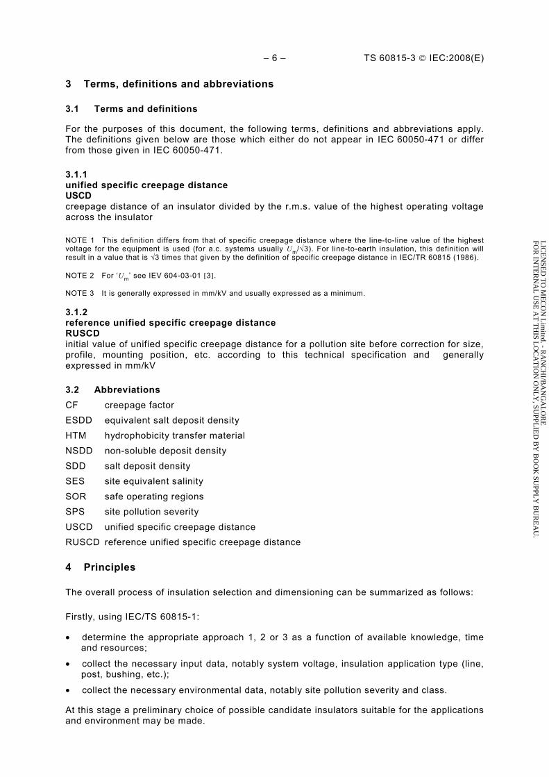
Profiles with shallow under-ribs (see Figure 5) provide additional protected creepage distance and are beneficial in areas with type B pollution, such as salt fog or spray as long as shed spacing is not reduced. Under-ribs are, in general, not suited for environments with type A pollution or in areas with long dry periods.
The alternating profile (see Figure 6) allows increased creepage per unit length while ensuring satisfactory wet performance and self-cleaning properties. For the purposes of this specification, an alternating shed arrangement is defined as having a minimum difference in shed overhang, either given as a percentage of shed overhang for smaller diameter insulators, or of at least 15 mm for larger diameter insulators, e.g. post and hollow insulators (see 9.1).
NOTE The difference in shed overhang is less critical for wet performance of polymer insulators than it is for glass or porcelain insulators, notably for smaller diameters where s/p is more pertinent. However for longer insulators, for systems at 300 kV and above, too small a shed spacing can have a significant influence on wet power frequency and switching impulse withstand behaviour.
LIC
EN
SED
TO
ME
CO
N L
imited. - R
AN
CH
I/BA
NG
AL
OR
EFO
R IN
TE
RN
AL
USE
AT
TH
IS LO
CA
TIO
N O
NL
Y, SU
PPLIE
D B
Y B
OO
K SU
PPLY
BU
RE
AU
.
TS 60815-3 © IEC:2008(E) – 11 –
Figure 5 – Typical deep under-rib profile
Figure 6 – Typical “alternating” profiles
IEC 1987/08
9 Checking of profile parameters
9.1 General remark
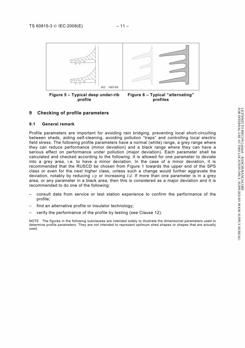
Profile parameters are important for avoiding rain bridging, preventing local short-circuiting between sheds, aiding self-cleaning, avoiding pollution “traps” and controlling local electric field stress. The following profile parameters have a normal (white) range, a grey range where they can reduce performance (minor deviation) and a black range where they can have a serious effect on performance under pollution (major deviation). Each parameter shall be calculated and checked according to the following. It is allowed for one parameter to deviate into a grey area, i.e. to have a minor deviation. In the case of a minor deviation, it is recommended that the RUSCD be chosen from Figure 1 towards the upper end of the SPS class or even for the next higher class, unless such a change would further aggravate the deviation, notably by reducing s/p or increasing l/d. If more than one parameter is in a grey area, or any parameter in a black area, then this is considered as a major deviation and it is recommended to do one of the following:
– consult data from service or test station experience to confirm the performance of the profile;
– find an alternative profile or insulator technology; – verify the performance of the profile by testing (see Clause 12).
NOTE The figures in the following subclauses are intended solely to illustrate the dimensional parameters used to determine profile parameters. They are not intended to represent optimum shed shapes or shapes that are actually used.
LIC
EN
SED
TO
ME
CO
N L
imited. - R
AN
CH
I/BA
NG
AL
OR
EFO
R IN
TE
RN
AL
USE
AT
TH
IS LO
CA
TIO
N O
NL
Y, SU
PPLIE
D B
Y B
OO
K SU
PPLY
BU
RE
AU
.
– 12 – TS 60815-3 © IEC:2008(E)
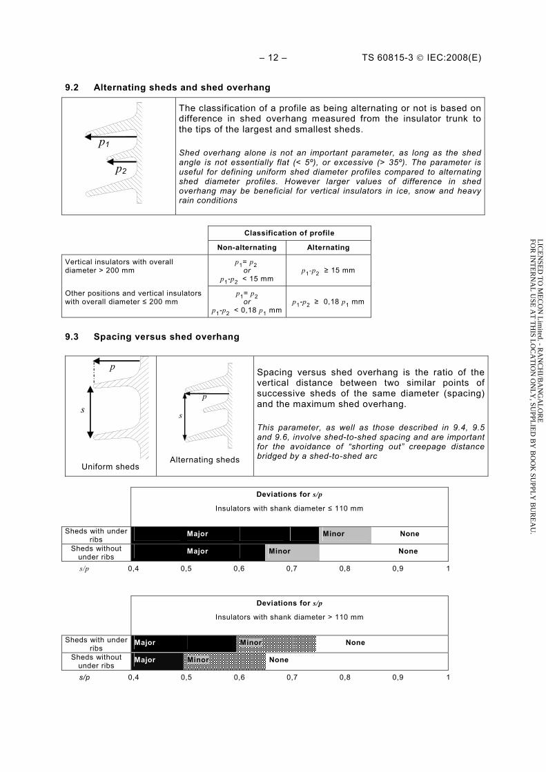
9.2 Alternating sheds and shed overhang
p2
p1
The classification of a profile as being alternating or not is based on difference in shed overhang measured from the insulator trunk to the tips of the largest and smallest sheds.
Shed overhang alone is not an important parameter, as long as the shed angle is not essentially flat (< 5º), or excessive (> 35º). The parameter is useful for defining uniform shed diameter profiles compared to alternating shed diameter profiles. However larger values of difference in shed overhang may be beneficial for vertical insulators in ice, snow and heavy rain conditions
Classification of profile
Non-alternating Alternating
Vertical insulators with overall diameter > 200 mm
p1= p2 or
p1-p2 < 15 mm p1-p2 ≥ 15 mm
Other positions and vertical insulators with overall diameter ≤ 200 mm
p1= p2 or
p1-p2 < 0,18 p1 mmp1-p2 ≥ 0,18 p1 mm
9.3 Spacing versus shed overhang
s
p
Uniform sheds
s
p
Alternating sheds
Spacing versus shed overhang is the ratio of the vertical distance between two similar points of successive sheds of the same diameter (spacing) and the maximum shed overhang.
This parameter, as well as those described in 9.4, 9.5 and 9.6, involve shed-to-shed spacing and are important for the avoidance of “shorting out” creepage distance bridged by a shed-to-shed arc
Deviations for s/p
Insulators with shank diameter ≤ 110 mm
Sheds with under ribs
Major Minor None
Sheds without under ribs
Major Minor None
s/p 0,4 0,5 0,6 0,7 0,8 0,9 1
Deviations for s/p
Insulators with shank diameter > 110 mm
Sheds with under ribs
Major Minor None
Sheds without under ribs
Major Minor None
s/p 0,4 0,5 0,6 0,7 0,8 0,9 1
LIC
EN
SED
TO
ME
CO
N L
imited. - R
AN
CH
I/BA
NG
AL
OR
EFO
R IN
TE
RN
AL
USE
AT
TH
IS LO
CA
TIO
N O
NL
Y, SU
PPLIE
D B
Y B
OO
K SU
PPLY
BU
RE
AU
.

TS 60815-3 © IEC:2008(E) – 13 –
9.4 Minimum distance between sheds
c
Uniform sheds
c
c
Alternating sheds
Not applicable to cap and pin insulators or pin insulators.
c is the minimum distance between adjacent sheds of the same diameter, measured by drawing a perpendicular from the lowest point of rim of the upper shed to the next shed below of the same diameter.
Minimum distance between sheds is one of the more important characteristics for insulator profile evaluation. Shed-to-shed arcing for small shed spacing can negate any effort to improve performance by adding creepage distance
Deviations for c
Uniform sheds Major Minor None Alternating
sheds Major Minor None
c (mm) 20 25 30 35 40 45 50
9.5 Creepage distance versus clearance
l1 d1
l2 d2
Alternating sheds
d is the straight air distance between two points on the insulating part or between a point on the insulating part and another on a metal part.
l is the part of the creepage distance measured between the above two points.
l/d is the highest ratio found on any section.
d l
Creepage distance versus clearance is a more localized check of the risk of bridging by arcs when dry bands or uneven hydrophobicity occur. It is also important in avoiding localized pollution build-up in deep and narrow sections of the profile Plain sheds
Deviations for l/d
All profiles None Minor Major
l1d1l2d2
l3d3
l/d 0 2 3 4 5 6 7
LIC
EN
SED
TO
ME
CO
N L
imited. - R
AN
CH
I/BA
NG
AL
OR
EFO
R IN
TE
RN
AL
USE
AT
TH
IS LO
CA
TIO
N O
NL
Y, SU
PPLIE
D B
Y B
OO
K SU
PPLY
BU
RE
AU
.
– 14 – TS 60815-3 © IEC:2008(E)
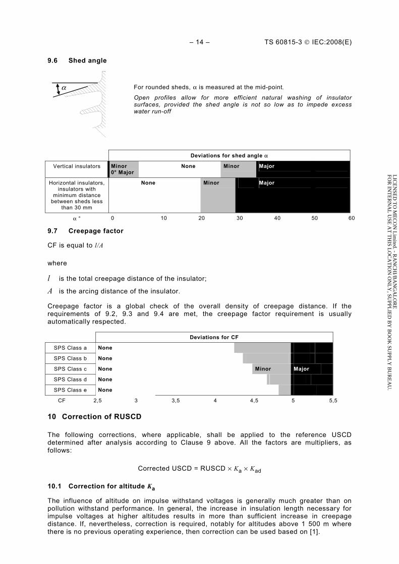
9.6 Shed angle
α
For rounded sheds, α is measured at the mid-point.
Open profiles allow for more efficient natural washing of insulator surfaces, provided the shed angle is not so low as to impede excess water run-off
Deviations for shed angle α
Vertical insulators Minor 0° Major
None Minor Major
Horizontal insulators, insulators with
minimum distance between sheds less
than 30 mm
None Minor Major
α ° 0 10 20 30 40 50 60
9.7 Creepage factor
CF is equal to l/A
where
l is the total creepage distance of the insulator;
A is the arcing distance of the insulator.
Creepage factor is a global check of the overall density of creepage distance. If the requirements of 9.2, 9.3 and 9.4 are met, the creepage factor requirement is usually automatically respected.
Deviations for CF
SPS Class a None
SPS Class b None
SPS Class c None Minor Major
SPS Class d None
SPS Class e None
CF 2,5 3 3,5 4 4,5 5 5,5
10 Correction of RUSCD
The following corrections, where applicable, shall be applied to the reference USCD determined after analysis according to Clause 9 above. All the factors are multipliers, as follows:
Corrected USCD = RUSCD × Ka × Kad
10.1 Correction for altitude Ka
The influence of altitude on impulse withstand voltages is generally much greater than on pollution withstand performance. In general, the increase in insulation length necessary for impulse voltages at higher altitudes results in more than sufficient increase in creepage distance. If, nevertheless, correction is required, notably for altitudes above 1 500 m where there is no previous operating experience, then correction can be used based on [1].
LIC
EN
SED
TO
ME
CO
N L
imited. - R
AN
CH
I/BA
NG
AL
OR
EFO
R IN
TE
RN
AL
USE
AT
TH
IS LO
CA
TIO
N O
NL
Y, SU
PPLIE
D B
Y B
OO
K SU
PPLY
BU
RE
AU
.
TS 60815-3 © IEC:2008(E) – 15 –
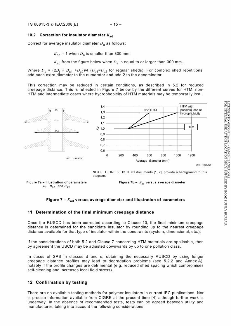
10.2 Correction for insulator diameter Kad
Correct for average insulator diameter Da as follows:
Kad = 1 when Da is smaller than 300 mm;
Kad from the figure below when Da is equal to or larger than 300 mm.
Where Da = (2Dt + Ds1 +Ds2)/4 (Ds1=Ds2 for regular sheds). For complex shed repetitions, add each extra diameter to the numerator and add 2 to the denominator.
This correction may be reduced in certain conditions, as described in 5.2 for reduced creepage distance. This is reflected in Figure 7 below by the different curves for HTM, non-HTM and intermediate cases where hydrophobicity of HTM materials may be temporarily lost.
0,6
0,7
0,8
0,9
1,0
1,1
1,2
1,3
1,4
0 200 400 600 800 1000 1200
Average diameter (mm)
Kad
HTM
HTM with possible loss of hydrophobicity
Non HTM
IEC 1990/08
Dt
Ds1
Ds2
IEC 1989/08
NOTE CIGRE 33.13 TF 01 documents [1, 2], provide a background to this diagram.
Figure 7b – Kad versus average diameter Figure 7a – Illustration of parameters Dt, Ds1, and Ds2
Figure 7 – Kad versus average diameter and illustration of parameters
11 Determination of the final minimum creepage distance
Once the RUSCD has been corrected according to Clause 10, the final minimum creepage distance is determined for the candidate insulator by rounding up to the nearest creepage distance available for that type of insulator within the constraints (system, dimensional, etc.).
If the considerations of both 5.2 and Clause 7 concerning HTM materials are applicable, then by agreement the USCD may be adjusted downwards by up to one pollution class.
In cases of SPS in classes d and e, obtaining the necessary RUSCD by using longer creepage distance profiles may lead to degradation problems (see 5.2.2 and Annex A), notably if the profile changes are detrimental (e.g. reduced shed spacing which compromises self-cleaning and increases local field stress).
12 Confirmation by testing
There are no available testing methods for polymer insulators in current IEC publications. Nor is precise information available from CIGRE at the present time [4] although further work is underway. In the absence of recommended tests, tests can be agreed between utility and manufacturer, taking into account the following considerations:
LIC
EN
SED
TO
ME
CO
N L
imited. - R
AN
CH
I/BA
NG
AL
OR
EFO
R IN
TE
RN
AL
USE
AT
TH
IS LO
CA
TIO
N O
NL
Y, SU
PPLIE
D B
Y B
OO
K SU
PPLY
BU
RE
AU
.
– 16 – TS 60815-3 © IEC:2008(E)
– for solid layer tests (generally representative of type A pollution), the testing of HTM insulators may require investigation of the performance in both hydrophilic and hydrophobic states;
– the measurement of SDD can be problematic for HTM insulators; – treatments enabling the application of solid layer may affect hydrophobicity; – for salt fog tests (generally representative of type B pollution), standard pre-conditioning
techniques may temporarily destroy hydrophobicity; – withstand determination tests where flashovers occur may also destroy hydrophobicity,
e.g. the “up and down” method.
LIC
EN
SED
TO
ME
CO
N L
imited. - R
AN
CH
I/BA
NG
AL
OR
EFO
R IN
TE
RN
AL
USE
AT
TH
IS LO
CA
TIO
N O
NL
Y, SU
PPLIE
D B
Y B
OO
K SU
PPLY
BU
RE
AU
.

TS 60815-3 © IEC:2008(E) – 17 –
Annex A (informative)
Background information on pollution induced degradation of polymers
As mentioned in 5.1, the kind of housing material itself and the design of the insulator can be decisive factors for the successful use of composite insulator in polluted conditions, notably concerning their long-term pollution withstand characteristics, stability of hydrophobicity and ageing behaviour. The generally higher pollution performance of a composite insulator, in comparison to conventional insulators is, for a given environment, due to several influences:
– smaller average diameter, notably in the case of suspension insulators; – finer, more open profiles due to reduced material thickness; – different material physical characteristics giving reduced thermal lag (less wetting due to
dew/mist) and altering pollution accumulation and arc propagation; – hydrophobic surfaces which reduce surface conductance and leakage current activity.
Because of the lack of experience with hydrophobic housing materials and the uncertainty of the long-term hydrophobicity behaviour, the linear creepage principle given by IEC/TR 60815:1986 was in most cases applied to all types of composite insulators. This design rule has been successfully applied to more than 95 % of all currently installed composite insulators. The service records of composite insulators gained over more than 25 years shows applicability of this method in most applications. Life-time is not limited either by insulation failures due to pollution, nor by damage caused by tracking and erosion.
In general, the long-term behaviour of a composite insulator depends on the overall and local electrical stress whose value, duration and position depends on pollution level, wetting, hydrophobicity loss/recovery and insulator profile. If the stress reaches a critical level it can either cause flashover (if creepage distance is too short) or local erosion or tracking. For a given environment and applied voltage, the following states can arise as creepage distance is increased:
– overall creepage too short: high mobility arcs leading to flashover; – longer overall creepage: high mobility arcs during extreme events, but no flashover,
localized stable arcs at other time leading to degradation; – overall creepage “just right”: Little or no arcing, no flashover, no degradation; – too much creepage distance in too short a length: localized stable arcs leading to
degradation; – very high creepage distance (with respect to the conditions): infrequent localized arcing,
no degradation.
Figure A.1 illustrates this by showing the general performance state of a composite insulator of fixed insulating length with varying USCD and depending on the degree of pollution (a combination of pollution and climatic conditions, expressed either by surface conductivity κS, ESDD plus wetting or other variables). The regions where risk of flashover or degradation are shown as safe operating regions (SOR). A typical linear principle of IEC/TR 60815:1986 is also shown in Figure A.1 (crossing SOR1/area 2, around the straight linear line).
Within area 1, the creepage distance is too low which will result in an increased flashover probability.
Within area 2/SOR1 the design and creepage distance are correct, which will result in minimal flashover and damage probability.
Within area 3 the creepage distance appears correct but is obtained by incorrect design which will result in increased damage probability.
LIC
EN
SED
TO
ME
CO
N L
imited. - R
AN
CH
I/BA
NG
AL
OR
EFO
R IN
TE
RN
AL
USE
AT
TH
IS LO
CA
TIO
N O
NL
Y, SU
PPLIE
D B
Y B
OO
K SU
PPLY
BU
RE
AU
.

– 18 – TS 60815-3 © IEC:2008(E)
Designs that fall in SOR1 are “best practice” according to flashover and tracking and erosion performance.
In some specific cases, such as pollution environments as per E6 or E7 in Table 5 of IEC/TS 60815-1, that are characterized generally by high conductivity κS of pollutants and a permanent loss of hydrophobicity (permanent wetting) of the insulator housing, tracking and erosion phenomena have to be considered as life-limiting effects even though the insulation withstand performance is normally not negatively affected. It is estimated that around 5 % of in-situ conditions present this special risk. The critical area regarding insulator ageing effects is described by area 3 in Figure A.1.
The hazards of tracking and erosion come into play if a critical conductivity κS or an equivalent pollution degree is exceeded. Area 3 is a critical design area regarding creepage distance design with respect to the pollution degree (surface conductivity). Within area 3, local arc stability and overall arc energy lead to maximum effect of discharge energy on the insulator housing, therefore leading to maximum local damage to housing materials and interfaces. Area 3 has to be avoided either by selecting lower creepage distances or by overdesigning quantity of creepage while avoiding increasing local stress (area 4).
The relation between the size and position of the areas and SOR and the values of the diagram axes depends on pollution, climate, the properties of the housing material and housing design, hence a general recommendation cannot be given here.
In general, field experience has shown that less creepage distance for composite insulators (e. g. one pollution class below the linear principle) can be an appropriate solution for this phenomenon. The slightly increased likelihood of pollution flashovers can be technically compensated with correspondingly designed arc protection devices.
It is highly recommended to execute outdoor testing for a certain time (e.g. one year), monitoring both electrical behaviour (leakage currents, flashovers) and housing and interface degradation. A guide for the installation of outdoor test stations will be published soon by CIGRE WG B2.03.
LIC
EN
SED
TO
ME
CO
N L
imited. - R
AN
CH
I/BA
NG
AL
OR
EFO
R IN
TE
RN
AL
USE
AT
TH
IS LO
CA
TIO
N O
NL
Y, SU
PPLIE
D B
Y B
OO
K SU
PPLY
BU
RE
AU
.

TS 60815-3 © IEC:2008(E) – 19 –
Insulation failure “pollution flashover”
(area 1)
κS (degree of pollution e.g. surface conductivity)
SOR1 (area 2)
Tracking and erosion “damage to housing”
(area 3)
Linear creepage principle
κS, critical
USCD (constant
insulator length)
IEC 1991/08
Figure A.1 – Operating areas as a function of pollution severity and USCD (for a fixed insulating length)
LIC
EN
SED
TO
ME
CO
N L
imited. - R
AN
CH
I/BA
NG
AL
OR
EFO
R IN
TE
RN
AL
USE
AT
TH
IS LO
CA
TIO
N O
NL
Y, SU
PPLIE
D B
Y B
OO
K SU
PPLY
BU
RE
AU
.
– 20 – TS 60815-3 © IEC:2008(E)
Bibliography
[1] CIGRE Taskforce 33.04.01 – Polluted insulators: A review of current knowledge, CIGRE brochure N° 158-2000
[2] CIGRE WG C4.303 – Outdoor insulation in polluted conditions: Guidelines for selection and dimensioning Part 1: General principles and the a.c. case, CIGRE Technical Brochure N° 361-2008
[3] IEC 60050-604, International Electrotechnical Vocabulary – Part 604: Generation, transmission and distribution of electricity – Operation
[4] CIGRE Taskforce 33.13.07 – Influence of ice and snow on the flashover performance of outdoor insulators – Part 1: Effects of ice, ELECTRA No. 187 December 1999, and Part 2: Effects of Snow, ELECTRA No. 188 February 2000
[5] CIGRE Report 142, Natural and artificial ageing and pollution testing of polymeric insulators, WG33-04-07 June 1999
[6] IEC 60507, Artificial pollution tests on high-voltage insulators to be used on a.c. systems
[7] IEC/TR 62039, Selection guide for polymeric materials for outdoor use under HV stress
___________
LIC
EN
SED
TO
ME
CO
N L
imited. - R
AN
CH
I/BA
NG
AL
OR
EFO
R IN
TE
RN
AL
USE
AT
TH
IS LO
CA
TIO
N O
NL
Y, SU
PPLIE
D B
Y B
OO
K SU
PPLY
BU
RE
AU
.

LIC
EN
SED
TO
ME
CO
N L
imited. - R
AN
CH
I/BA
NG
AL
OR
EFO
R IN
TE
RN
AL
USE
AT
TH
IS LO
CA
TIO
N O
NL
Y, SU
PPLIE
D B
Y B
OO
K SU
PPLY
BU
RE
AU
.

INTERNATIONAL ELECTROTECHNICAL COMMISSION 3, rue de Varembé PO Box 131 CH-1211 Geneva 20 Switzerland Tel: + 41 22 919 02 11 Fax: + 41 22 919 03 00 [email protected] www.iec.ch
LIC
EN
SED
TO
ME
CO
N L
imited. - R
AN
CH
I/BA
NG
AL
OR
EFO
R IN
TE
RN
AL
USE
AT
TH
IS LO
CA
TIO
N O
NL
Y, SU
PPLIE
D B
Y B
OO
K SU
PPLY
BU
RE
AU
.