Embed Size (px)
Citation preview
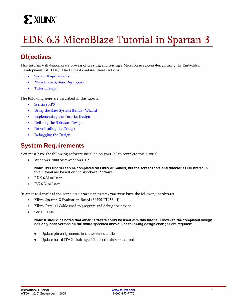
EDK 6.3 MicroBlaze Tutorial in Spartan 3ObjectivesThis tutorial will demonstrate process of creating and testing a MicroBlaze system design using the EmbeddedDevelopment Kit (EDK). The tutorial contains these sections:
System Requirements MicroBlaze System Description Tutorial Steps
The following steps are described in this tutorial: Starting XPS Using the Base System Builder Wizard Implementing the Tutorial Design Defining the Software Design Downloading the Design Debugging the Design
System RequirementsYou must have the following software installed on your PC to complete this tutorial:
Windows 2000 SP2/Windows XP
Note: This tutorial can be completed on Linux or Solaris, but the screenshots and directories illustrated inthis tutorial are based on the Windows Platform.
EDK 6.3i or later ISE 6.3i or later
In order to download the completed processor system, you must have the following hardware: Xilinx Spartan-3 Evaluation Board (3S200 FT256 -4) Xilinx Parallel Cable used to program and debug the device Serial Cable
Note: It should be noted that other hardware could be used with this tutorial. However, the completed designhas only been verified on the board specified above. The following design changes are required:
Update pin assignments in the system.ucf file Update board JTAG chain specified in the download.cmd
MicroBlaze Tutorial www.xilinx.com 1WT001 (v2.0) September 1, 2004 1-800-255-7778
EDK 6.3 MicroBlaze Tutorial in Spartan 3
MicroBlaze System DescriptionIn general, to design an embedded processor system, you need the following:
Hardware components Memory map Software application
Tutorial Design HardwareThe MicroBlaze (MB) tutorial design includes the following hardware components:
MicroBlaze Local Memory Bus (LMB) Bus
LMB_BRAM_IF_CNTLR BRAM_BLOCK
On-chip Peripheral Bus (OPB) BUS OPB_MDM OPB_UARTLITE 3 - OPB_GPIOs OPB_EMC
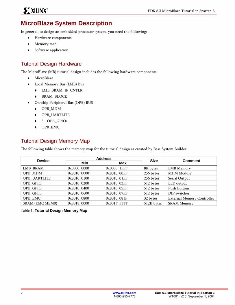
Tutorial Design Memory MapThe following table shows the memory map for the tutorial design as created by Base System Builder.
Device AddressMin Max Size Comment
LMB_BRAM 0x0000_0000 0x0000_1FFF 8K bytes LMB MemoryOPB_MDM 0x8010_0000 0x8010_00FF 256 bytes MDM ModuleOPB_UARTLITE 0x8010_0100 0x8010_01FF 256 bytes Serial OutputOPB_GPIO 0x8010_0200 0x8010_03FF 512 bytes LED outputOPB_GPIO 0x8010_0400 0x8010_05FF 512 bytes Push ButtonsOPB_GPIO 0x8010_0600 0x8010_07FF 512 bytes DIP switchesOPB_EMC 0x8010_0800 0x8010_081F 32 bytes External Memory ControllerSRAM (EMC MEM0) 0x8018_0000 0x801F_FFFF 512K bytes SRAM Memory
Table 1: Tutorial Design Memory Map
2 www.xilinx.com EDK 6.3 MicroBlaze Tutorial in Spartan 31-800-255-7778 WT001 (v2.0) September 1, 2004
EDK 6.3 MicroBlaze Tutorial in Spartan 3
Tutorial Steps
SetUp
Spartan-3 board with a RS-232 terminal connected to the serial port and configured for 57600 baud, with 8data bits, no parity and no handshakes.
Creating the Project File in XPSThe first step in this tutorial is using the Xilinx Platform Studio (XPS) to create a project file. XPS allows you tocontrol the hardware and software development of the MicroBlaze system, and includes the following:
An editor and a project management interface for creating and editing source code Software tool flow configuration options
You can use XPS to create the following files: Project Navigator project file that allows you to control the hardware implementation flow Microprocessor Software Specification (MHS) file
Note: For more information on the MHS file, refer to the “Microprocessor Hardware Specification (MHS)”chapter in the Embedded System Tools Guide.
Microprocessor Software Specification (MSS) file
Note: For more information on the MSS file, refer to the “Microprocessor Software Specification (MSS)”chapter in the Embedded System Tools Guide.
XPS supports the software tool flows associated with these software specifications. Additionally, you can use XPS tocustomize software libraries, drivers, and interrupt handlers, and to compile your programs.
I. Starting XPSTo open XPS, select the following:
Start → Programs → Xilinx Platform Studio 6.3 → Xilinx Platform Studio
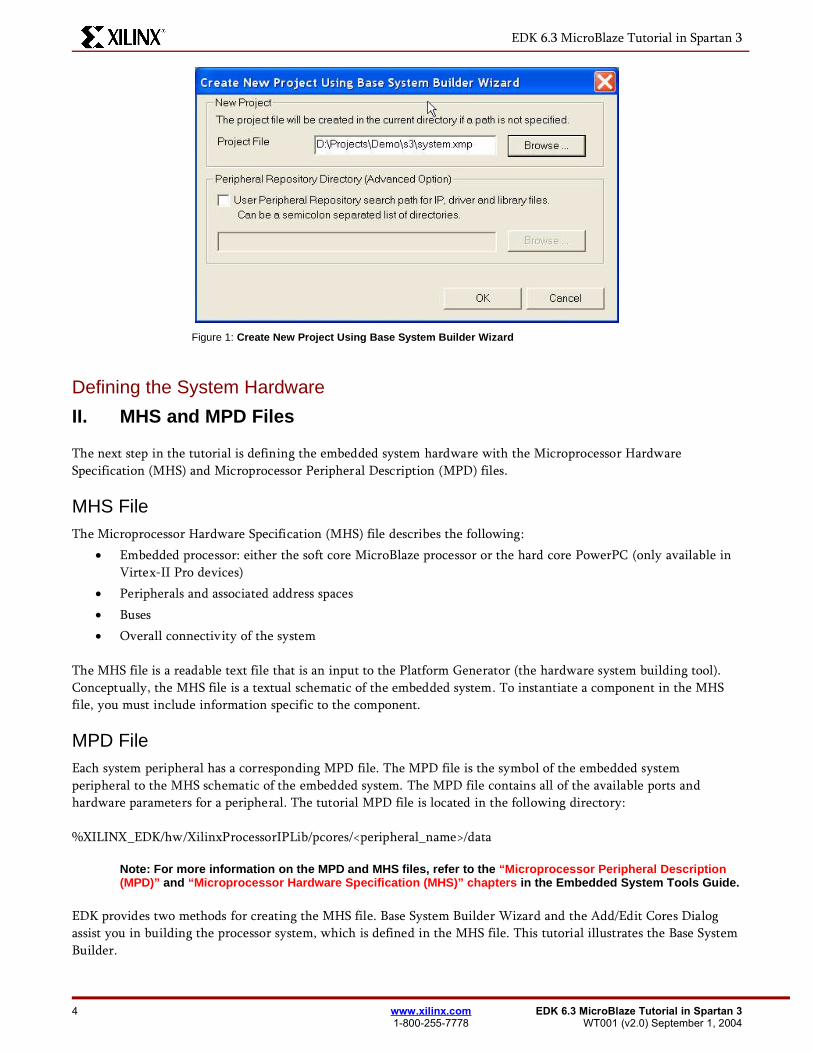
Select Base System Builder Wizard (BSB) to open the Create New Project Using BSB Wizard dialogbox shown in Figure 1.
Use the Project File Browse button to browse to the folder you want as your project directory.Click Open to create the system.xmp file.
Click Ok to start the BSB wizard.
Note: XPS does not support directory or project names which include spaces.
MicroBlaze Tutorial www.xilinx.com 3WT001 (v2.0) September 1, 2004 1-800-255-7778
EDK 6.3 MicroBlaze Tutorial in Spartan 3
Figure 1: Create New Project Using Base System Builder Wizard
Defining the System Hardware
II. MHS and MPD Files
The next step in the tutorial is defining the embedded system hardware with the Microprocessor HardwareSpecification (MHS) and Microprocessor Peripheral Description (MPD) files.
MHS FileThe Microprocessor Hardware Specification (MHS) file describes the following:
Embedded processor: either the soft core MicroBlaze processor or the hard core PowerPC (only available inVirtex-II Pro devices)
Peripherals and associated address spaces Buses Overall connectivity of the system
The MHS file is a readable text file that is an input to the Platform Generator (the hardware system building tool).Conceptually, the MHS file is a textual schematic of the embedded system. To instantiate a component in the MHSfile, you must include information specific to the component.
MPD FileEach system peripheral has a corresponding MPD file. The MPD file is the symbol of the embedded systemperipheral to the MHS schematic of the embedded system. The MPD file contains all of the available ports andhardware parameters for a peripheral. The tutorial MPD file is located in the following directory:
%XILINX_EDK/hw/XilinxProcessorIPLib/pcores/<peripheral_name>/data
Note: For more information on the MPD and MHS files, refer to the “Microprocessor Peripheral Description(MPD)” and “Microprocessor Hardware Specification (MHS)” chapters in the Embedded System Tools Guide.
EDK provides two methods for creating the MHS file. Base System Builder Wizard and the Add/Edit Cores Dialogassist you in building the processor system, which is defined in the MHS file. This tutorial illustrates the Base SystemBuilder.
4 www.xilinx.com EDK 6.3 MicroBlaze Tutorial in Spartan 31-800-255-7778 WT001 (v2.0) September 1, 2004
EDK 6.3 MicroBlaze Tutorial in Spartan 3
III. Using the Base System Builder Wizard
Use the following steps to create the processor system:
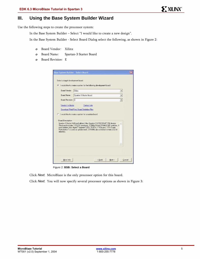
In the Base System Builder – Select “I would like to create a new design”.
In the Base System Builder - Select Board Dialog select the following, as shown in Figure 2:
o Board Vendor: Xilinxo Board Name: Spartan-3 Starter Boardo Board Revision: E
Figure 2: BSB: Select a Board
Click Next. MicroBlaze is the only processor option for this board.
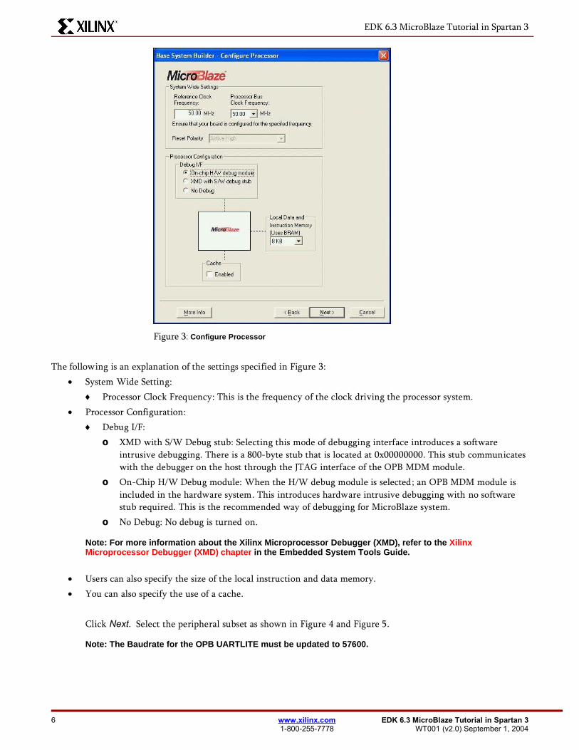
Click Next. You will now specify several processor options as shown in Figure 3:
MicroBlaze Tutorial www.xilinx.com 5WT001 (v2.0) September 1, 2004 1-800-255-7778
EDK 6.3 MicroBlaze Tutorial in Spartan 3
Figure 3: Configure Processor
The following is an explanation of the settings specified in Figure 3: System Wide Setting:
Processor Clock Frequency: This is the frequency of the clock driving the processor system. Processor Configuration:
Debug I/F:o XMD with S/W Debug stub: Selecting this mode of debugging interface introduces a software
intrusive debugging. There is a 800-byte stub that is located at 0x00000000. This stub communicateswith the debugger on the host through the JTAG interface of the OPB MDM module.
o On-Chip H/W Debug module: When the H/W debug module is selected; an OPB MDM module isincluded in the hardware system. This introduces hardware intrusive debugging with no softwarestub required. This is the recommended way of debugging for MicroBlaze system.
o No Debug: No debug is turned on.
Note: For more information about the Xilinx Microprocessor Debugger (XMD), refer to the XilinxMicroprocessor Debugger (XMD) chapter in the Embedded System Tools Guide.
Users can also specify the size of the local instruction and data memory. You can also specify the use of a cache.
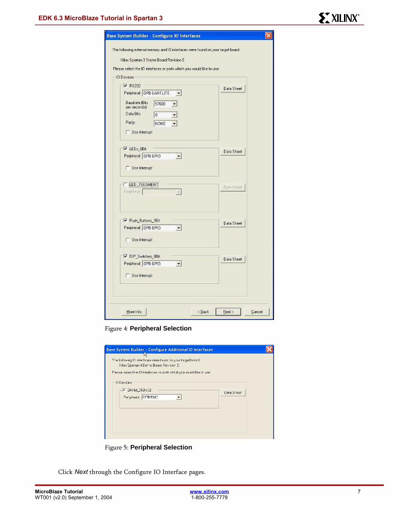
Click Next. Select the peripheral subset as shown in Figure 4 and Figure 5.
Note: The Baudrate for the OPB UARTLITE must be updated to 57600.
6 www.xilinx.com EDK 6.3 MicroBlaze Tutorial in Spartan 31-800-255-7778 WT001 (v2.0) September 1, 2004
EDK 6.3 MicroBlaze Tutorial in Spartan 3
Figure 4: Peripheral Selection
Figure 5: Peripheral Selection
Click Next through the Configure IO Interface pages.
MicroBlaze Tutorial www.xilinx.com 7WT001 (v2.0) September 1, 2004 1-800-255-7778
EDK 6.3 MicroBlaze Tutorial in Spartan 3
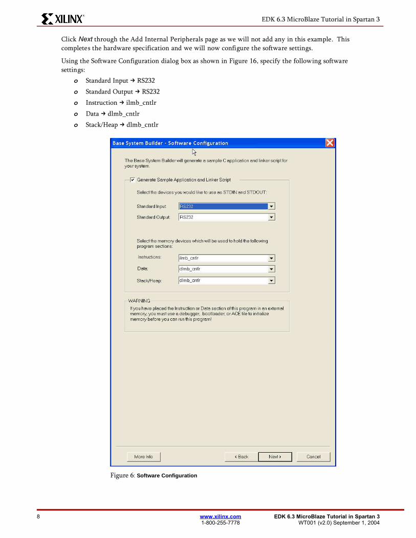
Click Next through the Add Internal Peripherals page as we will not add any in this example. Thiscompletes the hardware specification and we will now configure the software settings.
Using the Software Configuration dialog box as shown in Figure 16, specify the following softwaresettings:
o Standard Input → RS232
o Standard Output → RS232o Instruction → ilmb_cntlr
o Data → dlmb_cntlro Stack/Heap → dlmb_cntlr
Figure 6: Software Configuration
8 www.xilinx.com EDK 6.3 MicroBlaze Tutorial in Spartan 31-800-255-7778 WT001 (v2.0) September 1, 2004
EDK 6.3 MicroBlaze Tutorial in Spartan 3
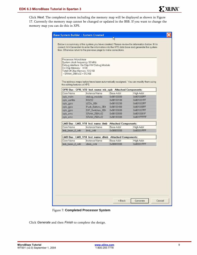
Click Next. The completed system including the memory map will be displayed as shown in Figure17. Currently the memory map cannot be changed or updated in the BSB. If you want to change thememory map you can do this in XPS.
Figure 7: Completed Processor System
Click Generate and then Finish to complete the design.
MicroBlaze Tutorial www.xilinx.com 9WT001 (v2.0) September 1, 2004 1-800-255-7778
EDK 6.3 MicroBlaze Tutorial in Spartan 3
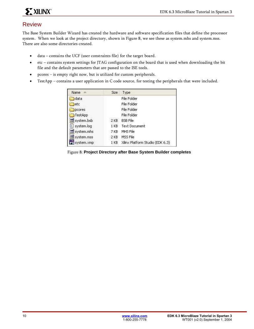
ReviewThe Base System Builder Wizard has created the hardware and software specification files that define the processorsystem. When we look at the project directory, shown in Figure 8, we see these as system.mhs and system.mss.There are also some directories created.
data – contains the UCF (user constraints file) for the target board. etc – contains system settings for JTAG configuration on the board that is used when downloading the bit
file and the default parameters that are passed to the ISE tools. pcores – is empty right now, but is utilized for custom peripherals. TestApp – contains a user application in C code source, for testing the peripherals that were included.
Figure 8: Project Directory after Base System Builder completes
10 www.xilinx.com EDK 6.3 MicroBlaze Tutorial in Spartan 31-800-255-7778 WT001 (v2.0) September 1, 2004
EDK 6.3 MicroBlaze Tutorial in Spartan 3
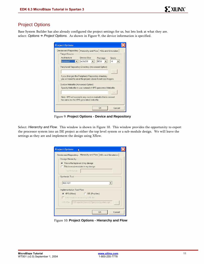
Project OptionsBase System Builder has also already configured the project settings for us, but lets look at what they are.select: Options → Project Options. As shown in Figure 9, the device information is specified.
Figure 9: Project Options - Device and Repository
Select: Hierarchy and Flow. This window is shown in Figure 10. This window provides the opportunity to exportthe processor system into an ISE project as either the top level system or a sub-module design. We will leave thesettings as they are and implement the design using Xflow.
Figure 10: Project Options - Hierarchy and Flow
MicroBlaze Tutorial www.xilinx.com 11WT001 (v2.0) September 1, 2004 1-800-255-7778
EDK 6.3 MicroBlaze Tutorial in Spartan 3
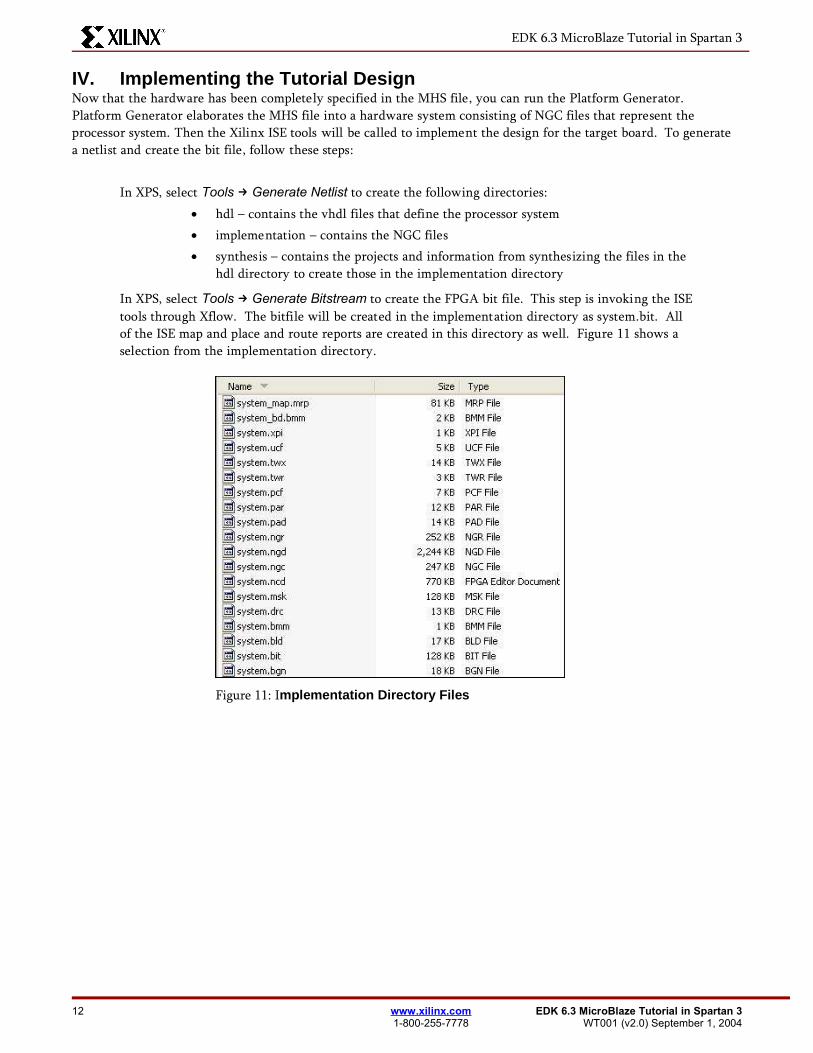
IV. Implementing the Tutorial DesignNow that the hardware has been completely specified in the MHS file, you can run the Platform Generator.Platform Generator elaborates the MHS file into a hardware system consisting of NGC files that represent theprocessor system. Then the Xilinx ISE tools will be called to implement the design for the target board. To generatea netlist and create the bit file, follow these steps:
In XPS, select Tools → Generate Netlist to create the following directories: hdl – contains the vhdl files that define the processor system implementation – contains the NGC files synthesis – contains the projects and information from synthesizing the files in the
hdl directory to create those in the implementation directory
In XPS, select Tools → Generate Bitstream to create the FPGA bit file. This step is invoking the ISEtools through Xflow. The bitfile will be created in the implementation directory as system.bit. Allof the ISE map and place and route reports are created in this directory as well. Figure 11 shows aselection from the implementation directory.
Figure 11: Implementation Directory Files
12 www.xilinx.com EDK 6.3 MicroBlaze Tutorial in Spartan 31-800-255-7778 WT001 (v2.0) September 1, 2004
EDK 6.3 MicroBlaze Tutorial in Spartan 3
V. Defining the Software Design
Now that the hardware design is completed, the next step is defining the software design. There are two major partsto software design, configuring the Board Support Package (BSP) and writing the software applications. Theconfiguration of the BSP includes the selection of device drivers and libraries.
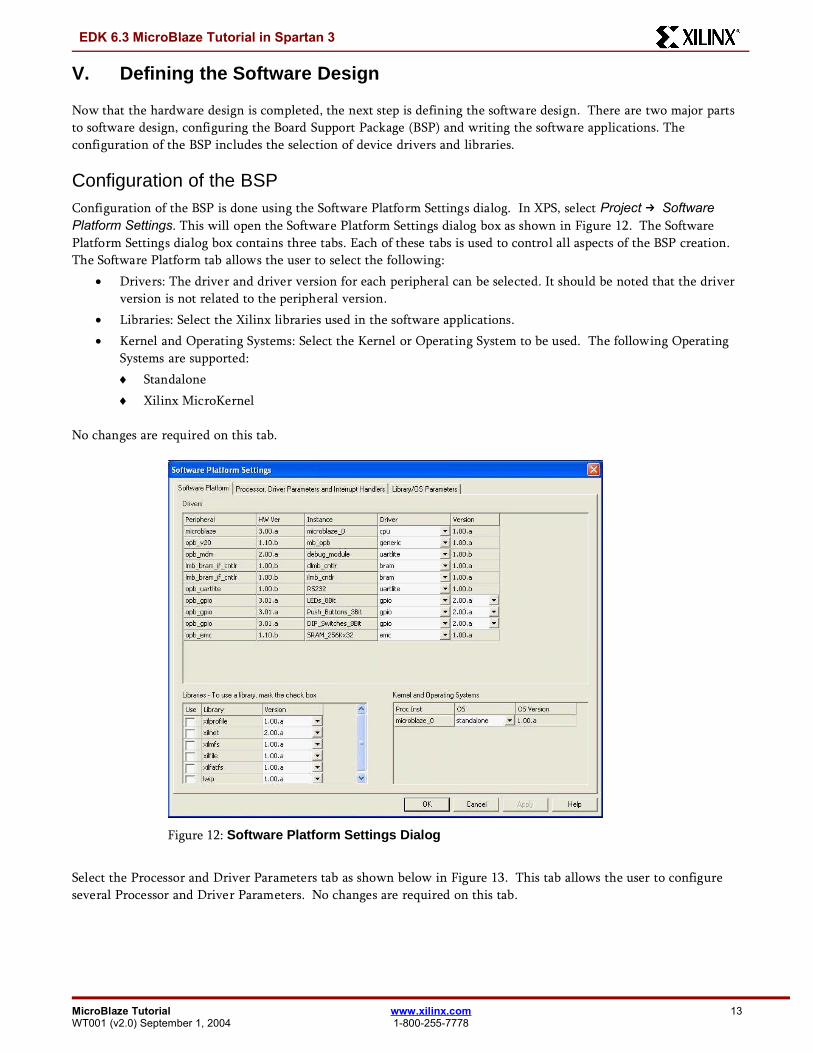
Configuration of the BSPConfiguration of the BSP is done using the Software Platform Settings dialog. In XPS, select Project → SoftwarePlatform Settings. This will open the Software Platform Settings dialog box as shown in Figure 12. The SoftwarePlatform Settings dialog box contains three tabs. Each of these tabs is used to control all aspects of the BSP creation.The Software Platform tab allows the user to select the following:
Drivers: The driver and driver version for each peripheral can be selected. It should be noted that the driverversion is not related to the peripheral version.
Libraries: Select the Xilinx libraries used in the software applications. Kernel and Operating Systems: Select the Kernel or Operating System to be used. The following Operating
Systems are supported: Standalone Xilinx MicroKernel
No changes are required on this tab.
Figure 12: Software Platform Settings Dialog
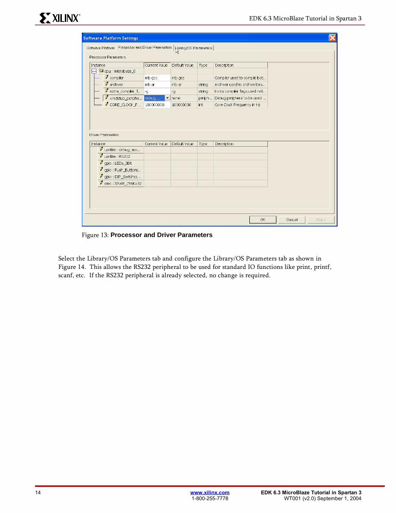
Select the Processor and Driver Parameters tab as shown below in Figure 13. This tab allows the user to configureseveral Processor and Driver Parameters. No changes are required on this tab.
MicroBlaze Tutorial www.xilinx.com 13WT001 (v2.0) September 1, 2004 1-800-255-7778
EDK 6.3 MicroBlaze Tutorial in Spartan 3
Figure 13: Processor and Driver Parameters
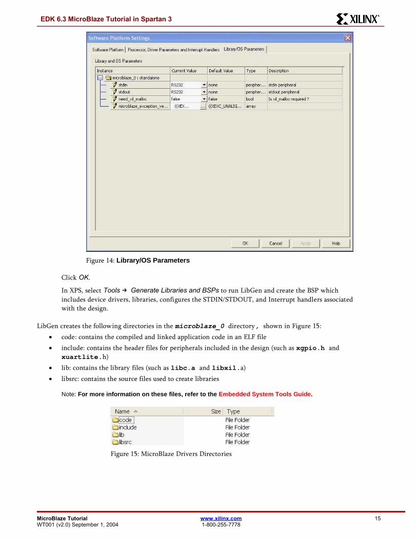
Select the Library/OS Parameters tab and configure the Library/OS Parameters tab as shown inFigure 14. This allows the RS232 peripheral to be used for standard IO functions like print, printf,scanf, etc. If the RS232 peripheral is already selected, no change is required.
14 www.xilinx.com EDK 6.3 MicroBlaze Tutorial in Spartan 31-800-255-7778 WT001 (v2.0) September 1, 2004
EDK 6.3 MicroBlaze Tutorial in Spartan 3
Figure 14: Library/OS Parameters
Click OK.
In XPS, select Tools → Generate Libraries and BSPs to run LibGen and create the BSP whichincludes device drivers, libraries, configures the STDIN/STDOUT, and Interrupt handlers associatedwith the design.
LibGen creates the following directories in the microblaze_0 directory, shown in Figure 15: code: contains the compiled and linked application code in an ELF file include: contains the header files for peripherals included in the design (such as xgpio.h and
xuartlite.h) lib: contains the library files (such as libc.a and libxil.a) libsrc: contains the source files used to create libraries
Note: For more information on these files, refer to the Embedded System Tools Guide.
Figure 15: MicroBlaze Drivers Directories
MicroBlaze Tutorial www.xilinx.com 15WT001 (v2.0) September 1, 2004 1-800-255-7778
EDK 6.3 MicroBlaze Tutorial in Spartan 3
Building the User ApplicationIn EDK 6.3, XPS provides the ability for the user to create multiple software projects. These projects can include source files,header files, and linker scripts. Unique software projects allows the designer to specify the following options for eachsoftware project:
Specify compiler options Specify which projects to compile Specify which projects to downloaded Build entire projects
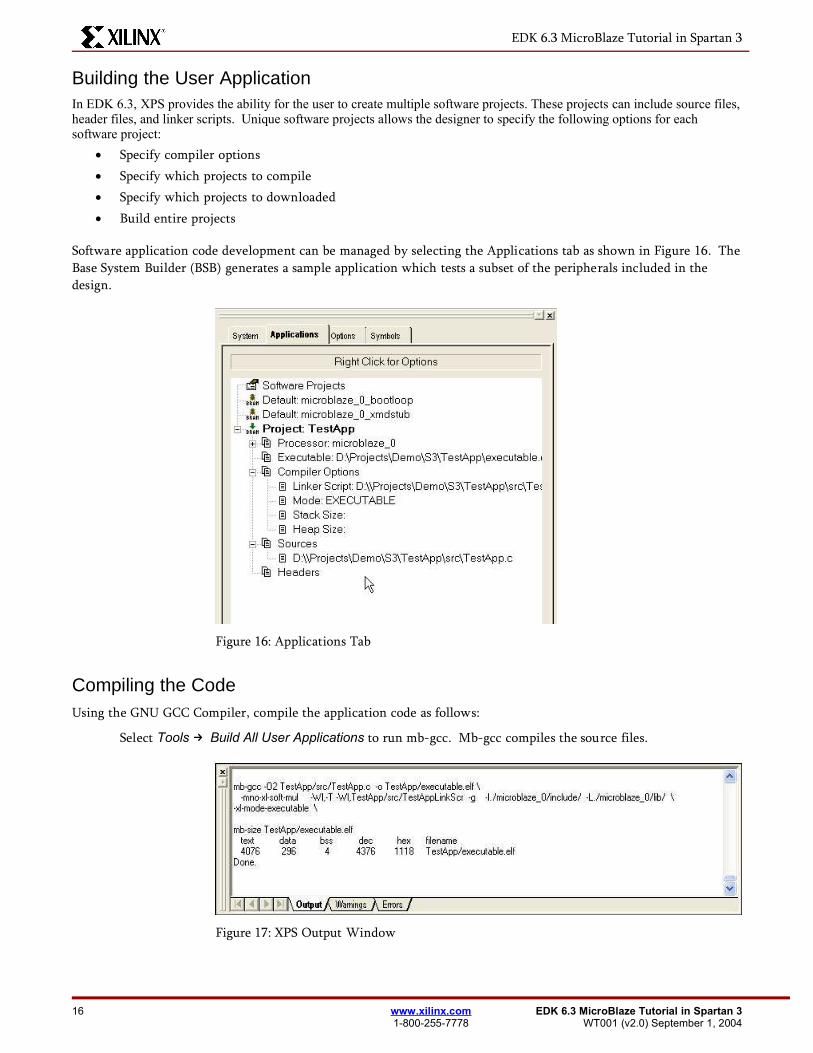
Software application code development can be managed by selecting the Applications tab as shown in Figure 16. TheBase System Builder (BSB) generates a sample application which tests a subset of the peripherals included in thedesign.
Figure 16: Applications Tab
Compiling the CodeUsing the GNU GCC Compiler, compile the application code as follows:
Select Tools → Build All User Applications to run mb-gcc. Mb-gcc compiles the source files.
Figure 17: XPS Output Window
16 www.xilinx.com EDK 6.3 MicroBlaze Tutorial in Spartan 31-800-255-7778 WT001 (v2.0) September 1, 2004
EDK 6.3 MicroBlaze Tutorial in Spartan 3
VI. Downloading the Design
Now that the hardware and software designs are completed, the device can be configured. Follow these steps todownload and configure the FGPA:
Connect the host computer to the target board, including connecting the Parallel-JTAG cable andthe serial cable.
Start a hyperterminal session with the following settings: com1 – This is dependant on the com port your serial cable is connected to. Bits per second: 57600 Data bits: 8 Parity: none Stop bits: 1 Flow control: none
Connect the board power.
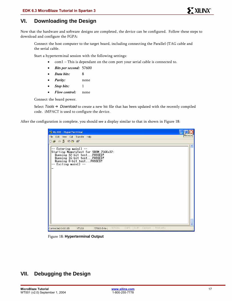
Select Tools → Download to create a new bit file that has been updated with the recently compiledcode. iMPACT is used to configure the device.
After the configuration is complete, you should see a display similar to that in shown in Figure 18:
Figure 18: Hyperterminal Output
VII. Debugging the Design
MicroBlaze Tutorial www.xilinx.com 17WT001 (v2.0) September 1, 2004 1-800-255-7778
EDK 6.3 MicroBlaze Tutorial in Spartan 3
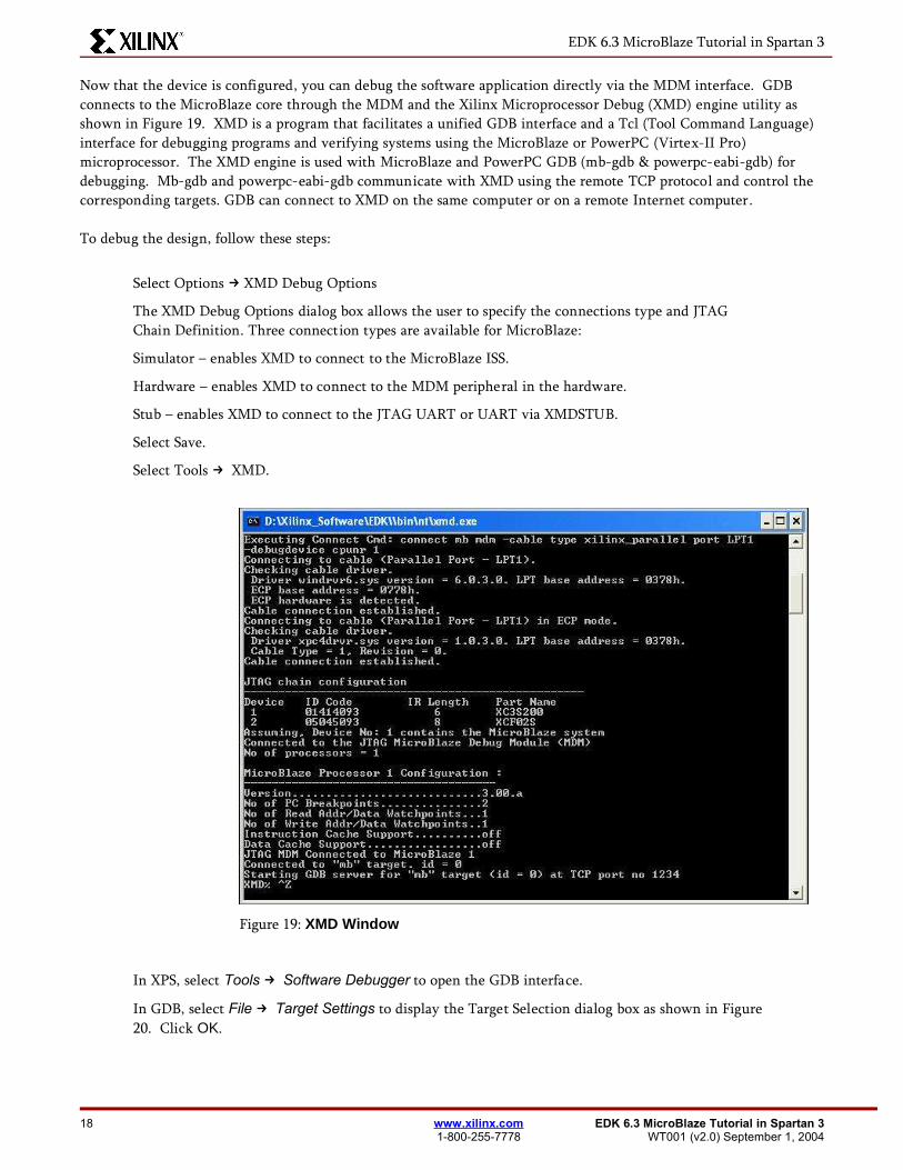
Now that the device is configured, you can debug the software application directly via the MDM interface. GDBconnects to the MicroBlaze core through the MDM and the Xilinx Microprocessor Debug (XMD) engine utility asshown in Figure 19. XMD is a program that facilitates a unified GDB interface and a Tcl (Tool Command Language)interface for debugging programs and verifying systems using the MicroBlaze or PowerPC (Virtex-II Pro)microprocessor. The XMD engine is used with MicroBlaze and PowerPC GDB (mb-gdb & powerpc-eabi-gdb) fordebugging. Mb-gdb and powerpc-eabi-gdb communicate with XMD using the remote TCP protocol and control thecorresponding targets. GDB can connect to XMD on the same computer or on a remote Internet computer.
To debug the design, follow these steps:
Select Options XMD Debug Options→
The XMD Debug Options dialog box allows the user to specify the connections type and JTAGChain Definition. Three connection types are available for MicroBlaze:
Simulator – enables XMD to connect to the MicroBlaze ISS.
Hardware – enables XMD to connect to the MDM peripheral in the hardware.
Stub – enables XMD to connect to the JTAG UART or UART via XMDSTUB.
Select Save.
Select Tools → XMD.
Figure 19: XMD Window
In XPS, select Tools → Software Debugger to open the GDB interface.
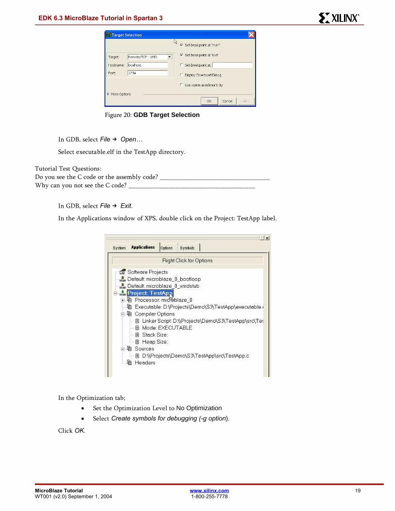
In GDB, select File → Target Settings to display the Target Selection dialog box as shown in Figure20. Click OK.
18 www.xilinx.com EDK 6.3 MicroBlaze Tutorial in Spartan 31-800-255-7778 WT001 (v2.0) September 1, 2004
EDK 6.3 MicroBlaze Tutorial in Spartan 3
Figure 20: GDB Target Selection
In GDB, select File → Open…
Select executable.elf in the TestApp directory.
Tutorial Test Questions:Do you see the C code or the assembly code? _________________________________Why can you not see the C code? ______________________________________
In GDB, select File → Exit.
In the Applications window of XPS, double click on the Project: TestApp label.
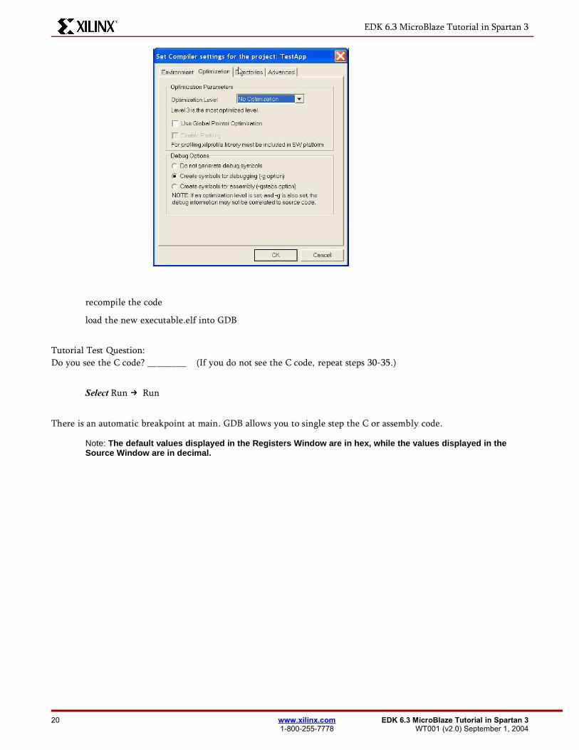
In the Optimization tab; Set the Optimization Level to No Optimization
Select Create symbols for debugging (-g option).
Click OK.
MicroBlaze Tutorial www.xilinx.com 19WT001 (v2.0) September 1, 2004 1-800-255-7778
EDK 6.3 MicroBlaze Tutorial in Spartan 3
recompile the code
load the new executable.elf into GDB
Tutorial Test Question:Do you see the C code? ________ (If you do not see the C code, repeat steps 30-35.)
Select Run → Run
There is an automatic breakpoint at main. GDB allows you to single step the C or assembly code.
Note: The default values displayed in the Registers Window are in hex, while the values displayed in theSource Window are in decimal.
20 www.xilinx.com EDK 6.3 MicroBlaze Tutorial in Spartan 31-800-255-7778 WT001 (v2.0) September 1, 2004