Embed Size (px)
Citation preview
Spartan-6 LX9 MicroBoard Tutorial
Spartan-6 LX9 MicroBoard Embedded Tutorial
Lab 6
Creating a MicroBlaze SPI Flash Bootloader
Version 13.1.01
Spartan-6 LX9 MicroBoard Tutorial
Page 2 of 18 2
Revision History
Version Description Date
13.1.01 Initial release for EDK 13.1 5/17/11
Table of Contents
Revision History .............................................................................................................................. 2 Table of Contents ........................................................................................................................... 2 Table of Figures .............................................................................................................................. 2 Overview......................................................................................................................................... 3 Objectives ....................................................................................................................................... 4 Requirements ................................................................................................................................. 5
Software ...................................................................................................................................... 5 Hardware .................................................................................................................................... 5 Recommended Reading ............................................................................................................. 5
Tutorial Steps ................................................................................................................................. 6 Create the MicroBlaze System .................................................................................................... 6 Create a New Software Application Running from LPDDR ......................................................... 9 Create the Boot Loader Application .......................................................................................... 10 Programming the SPI Flash Using iMPACT.............................................................................. 12
Getting Help and Support ............................................................................................................. 18
Table of Figures
Figure 1 - Hardware Platform ......................................................................................................... 3 Figure 2 - XPS Clock Wizard .......................................................................................................... 7 Figure 3 - Application Build Settings ............................................................................................. 10 Figure 4 - ISF Library .................................................................................................................... 11 Figure 5 - ISF Library Setting........................................................................................................ 11 Figure 6 - Program FPGA Window ............................................................................................... 12 Figure 7 - Virtual COM Port Assigned to MicroBoard ................................................................... 13 Figure 8 - Storage Target ............................................................................................................. 13 Figure 9 - Storage Device Size ..................................................................................................... 14 Figure 10 - Enter Data Step .......................................................................................................... 14 Figure 11 - Data File Assignment ................................................................................................. 15 Figure 12 - Data File Assignment ................................................................................................. 16 Figure 13 - SPI Flash Selection .................................................................................................... 16 Figure 14 - Terminal Window showing FPGA Running ................................................................ 17
Spartan-6 LX9 MicroBoard Tutorial
Page 3 of 18
Overview
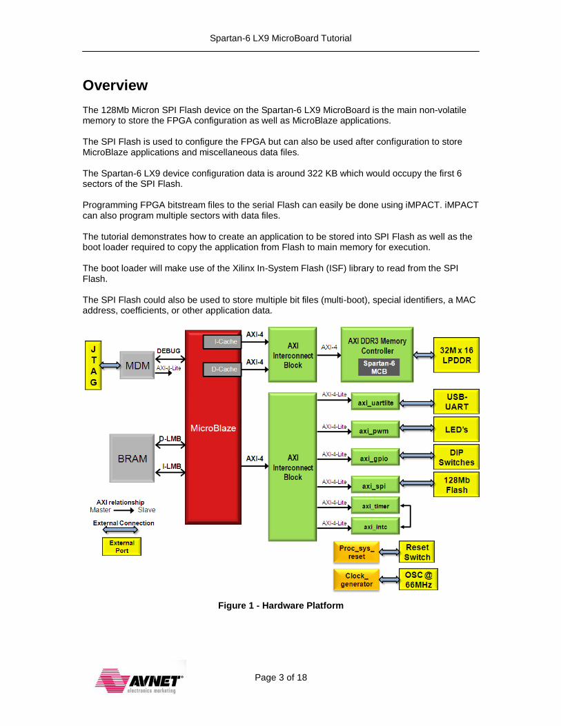
The 128Mb Micron SPI Flash device on the Spartan-6 LX9 MicroBoard is the main non-volatile memory to store the FPGA configuration as well as MicroBlaze applications. The SPI Flash is used to configure the FPGA but can also be used after configuration to store MicroBlaze applications and miscellaneous data files. The Spartan-6 LX9 device configuration data is around 322 KB which would occupy the first 6 sectors of the SPI Flash. Programming FPGA bitstream files to the serial Flash can easily be done using iMPACT. iMPACT can also program multiple sectors with data files. The tutorial demonstrates how to create an application to be stored into SPI Flash as well as the boot loader required to copy the application from Flash to main memory for execution. The boot loader will make use of the Xilinx In-System Flash (ISF) library to read from the SPI Flash. The SPI Flash could also be used to store multiple bit files (multi-boot), special identifiers, a MAC address, coefficients, or other application data.
Figure 1 - Hardware Platform

Spartan-6 LX9 MicroBoard Tutorial
Page 4 of 18
Objectives
This tutorial will demonstrate how to do the following:
Create a MicroBlaze design with SPI Flash
Create an application running in LPDDR using SDK
Create an SPI boot loader running from internal BRAMs
Program the FPGA bitstream and MicroBlaze application into the SPI using iMPACT
Spartan-6 LX9 MicroBoard Tutorial
Page 5 of 18
Requirements
The following items are required for proper completion of this tutorial.
Software The following software setup is required to test this reference design:
WindowsXP 32-bit Service Pack 2
Xilinx ISE WebPack with the EDK add-on or ISE Embedded Edition version 13.1
Installed Digilent Adept and Xilinx 3rd
-party USB Cable driver (see Spartan-6 LX9 MicroBoard Configuration Guide, listed in Recommended Reading, below)
Installed Silicon Labs CP210x USB-to-UART Bridge Driver (see Silicon Labs CP210x USB-to-UART Setup Guide, listed in Recommended Reading, below)
Installation of the Spartan-6 LX9 MicroBoard IPXACT files (Available from Avnet: http://em.avnet.com/s6microboard)
Hardware The hardware setup used by this reference design includes:
Computer with a minimum of 300-900 MB (depending on O/S) to complete an XC6SLX9 design
1
Avnet Spartan-6 LX9 MicroBoard Kit o Avnet Spartan-6 LX9 MicroBoard o USB Extension cable (if necessary) o USB A-to-MicroB cable
Recommended Reading Available from Avnet: http://em.avnet.com/s6microboard
The hardware used on the Spartan-6 LX9 MicroBoard is described in detail in Avnet document, Spartan-6 LX9 MicroBoard User Guide.
An overview of the configuration options available on the Spartan-6 LX9 MicroBoard, as well as Digilent driver installation instructions can be found in the Avnet document, Spartan-6 LX9 MicroBoard Configuration Guide.
Instructions on installing the Silicon Labs CP210x USB-to-UART drivers can be found in the Avnet document, Silicon Labs CP210x USB-to-UART Setup Guide.
Available from Xilinx: http://www.xilinx.com/support/documentation/spartan-6.htm
Details on the Spartan-6 FPGA family are included in the following Xilinx documents: o Spartan-6 Family Overview (DS160) o Spartan-6 FPGA Data Sheet (DS162) o Spartan-6 FPGA Configuration User Guide (UG380) o Platform Studio Help (available in tool menu) o Platform Studio SDK Help (available in tool menu) o MicroBlaze Reference Guide v.13.1 (UG081) o Embedded System Tools Reference Manual v.13.1 (UG111) o Xilinx ISF library documentation
1 Refer to www.xilinx.com/ise/products/memory.htm

Spartan-6 LX9 MicroBoard Tutorial
Page 6 of 18
Tutorial Steps
Create the MicroBlaze System We will use Base System Builder to create a standard MicroBlaze embedded system with external memory and some basic peripherals. 1. Start Xilinx ISE Project Navigator, Start Programs Xilinx ISE Design Suite 13.1
ISE Design Tools Project Navigator and create a new project: File > New Project… 2. Set the Project Location to C:\Xilinx\Embedded\ and the Project Name to EDK_Bootloader.
Click Next. 3. Select Spartan6, XC6SLX9, CSG324, -2. For this tutorial, pick VHDL as the Preferred
Language. Click Next. NOTE: The default speed grade is -3, don’t forget to change this. 4. Click Finish. 5. Go to Project > New Source… then select Embedded Processor. Type mb_system for
the File name. Click Next. Click Finish.
6. Click YES to start Base System Builder Wizard.
7. Browse to a working directory. For example C:\Xilinx\Embedded\S6LX9_MB_SPI. Click Save then OK.
8. Select a AXI system then click OK.
9. Click Next to create a new design.
10. Select the Avnet Spartan-6 LX9 MicroBoard, Board Revision B, and click Next.
11. Click Next for a single processor system.
12. Select 16 KB of Local Memory then click Next.
13. Remove the CDCE913_I2C, LED_4Bits and Ethernet controllers and click Next.
14. Select 2 KB of Instruction and Data cache then click Next.
15. Click Next then Finish.
The Micron SPI Flash can run up to 54 MHz for read instructions. The SPI core is running at 50 MHz, however the maximum SCK frequency runs at half that rate, thus 25MHz. We will use the XPS Clocking Wizard to change peripheral clock rate to 100MHz and the default SCK clock ratio to provide a 50 MHz SPI clock.
16. Double-click on the SPI_FLASH instance in the System Assembly View.
17. Change the Ratio of AXI Clock Frequency To SCK Frequency parameter to 2 then click OK.
Spartan-6 LX9 MicroBoard Tutorial
Page 7 of 18
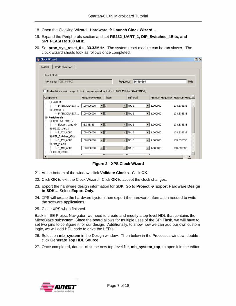
18. Open the Clocking Wizard, Hardware Launch Clock Wizard…
19. Expand the Peripherals section and set RS232_UART_1, DIP_Switches_4Bits, and SPI_FLASH to 100 MHz.
20. Set proc_sys_reset_0 to 33.33MHz. The system reset module can be run slower. The
clock wizard should look as follows once completed.
Figure 2 - XPS Clock Wizard
21. At the bottom of the window, click Validate Clocks. Click OK.
22. Click OK to exit the Clock Wizard. Click OK to accept the clock changes.
23. Export the hardware design information for SDK. Go to Project Export Hardware Design to SDK… Select Export Only.
24. XPS will create the hardware system then export the hardware information needed to write the software applications.
25. Close XPS when finished.
Back in ISE Project Navigator, we need to create and modify a top-level HDL that contains the MicroBlaze subsystem. Since the board allows for multiple uses of the SPI Flash, we will have to set two pins to configure it for our design. Additionally, to show how we can add our own custom logic, we will add HDL code to drive the LED’s.
26. Select on mb_system in the Design window. Then below in the Processes window, double-click Generate Top HDL Source.
27. Once completed, double-click the new top-level file, mb_system_top, to open it in the editor.
Spartan-6 LX9 MicroBoard Tutorial
Page 8 of 18
28. Add the two SPI Flash Control pins and LED outputs:
Add these two VHDL libraries at the top of the file, under library IEEE;
use IEEE.STD_LOGIC_ARITH.ALL; use IEEE.STD_LOGIC_UNSIGNED.ALL;
Add these three lines in the mb_system entity declaration. Copy them immediately below the other SPI_FLASH entries.
SPI_FLASH_SPI_HOLDn : out std_logic; SPI_FLASH_SPI_Wn : out std_logic; LEDs : out std_logic_vector(3 downto 0);
Immediately below, “architecture STRUCTURE of mb_system_top is” add this line:
signal led_count : std_logic_vector(26 downto 0);
Immediately above the “end architecture STRUCTURE;” Add this code:
SPI_FLASH_SPI_HOLDn <= '1'; SPI_FLASH_SPI_Wn <= '1';
process (CLK_66MHZ)
begin
if CLK_66MHZ='1' and CLK_66MHZ'event then
led_count <= led_count + 1;
end if;
end process;
LEDs <= led_count(26 downto 23); -- connects led outputs to counter value
29. Next we need to add and modify the user constraint file (UCF) that is provided from XPS. Go to Project Add source and select mb_system.ucf from the mb_system/data directory.
30. The UCF file needs be modified to constrain the two SPI Flash pins, four LEDs and set the VCCAUX voltage to 3.3V. Double-click mb_system.ucf and copy these lines into it. Save
the UCF file and close it. These
NET LEDs[0] LOC = "P4" | IOSTANDARD = "LVCMOS18";
NET LEDs[1] LOC = "L6" | IOSTANDARD = "LVCMOS18";
NET LEDs[2] LOC = "F5" | IOSTANDARD = "LVCMOS18";
NET LEDs[3] LOC = "C2" | IOSTANDARD = "LVCMOS18";
NET SPI_FLASH_SPI_HOLDn LOC="V14" | IOSTANDARD = "LVCMOS33";
NET SPI_FLASH_SPI_Wn LOC="T14" | IOSTANDARD = "LVCMOS33";
CONFIG VCCAUX = "3.3" ;
31. In the Design window, select the newly-created, mb_system_top, and in the Processes double-click Generate Programming File. This takes between 5 and 8 minutes to complete.

Spartan-6 LX9 MicroBoard Tutorial
Page 9 of 18
Create a New Software Application Running from LPDDR We will use SDK to create a simple hello world application which will run from DDR memory. The application will be stored in SPI Flash later in the tutorial. A boot loader will then copy the application from SPI Flash to DDR where it will execute. 1. Launch Xilinx SDK by selecting Start All Programs Xilinx ISE Design Suite 13.1
EDK Xilinx Software Development Kit.
2. Create a Workspace named WorkSpace in the EDK_Bootloader directory. Click OK.
3. Go to File > New > Xilinx C Project to create a new C project.
4. Click on Specify to indicate the hardware design we will be using. A Xilinx C application needs to be associated with a valid MicroBlaze hardware design.
5. Click on Browse in the Target Hardware Specification section. Browse to the EDK_Tutorial\mb_system\SDK\SDK_Export\hw\ directory and select the mb_system.xml file. Click Finish.
6. Select the Hello World application from the project templates then click Next.
7. Change the Board Support Package project name to Standalone_BSP.
8. Click Finish.
SDK will compile the Board Support Package and the C application.
In the previous tutorials, we’ve been loading a bootloop into the MicroBlaze’s local block RAM memory. At bootup, the bootloop application basically keep the MicroBlaze idling. We’ve then downloaded our application to the MicroBlaze’s block RAM though the JTAG interface.
In the next section, we will create a bootloader that at startup will copy our application from Flash memory to the LPDDR, then execute it. The first step is to assign our application into the LPDDR’s memory space. We will do this by updating the linker script.
9. Right-click on the hello_world_0 project and select Generate Linker Script.
10. Use the drop-down list to select the DDR memory, MCB3_LPDDR_S0_AXI_BASEADDR, for all the code sections. Click Generate then Yes to overwrite the existing linker script.
The next step is to create an image of our application that we can store in Flash memory. We could load the application as a binary file, HEX file, or SREC file into the Flash memory. The S-record (SREC) format is the most flexible since it only contains address and data information that are valid for the application. It will also allow us to use the boot loader application template provided in SDK.
11. Open a Xilinx Bash Shell. Go to Xilinx Tools > Launch Shell.
12. Navigate to the hello world application. Type: cd hello_world_0/Debug
13. Create an SREC version of the executable. Type:
mb-objcopy –O srec hello_world_0.elf hello_world_0.srec
14. This will complete quickly, type DIR to validate the new SREC file is in the directory.
15. Exit the Bash Shell, Type exit.
Spartan-6 LX9 MicroBoard Tutorial
Page 10 of 18
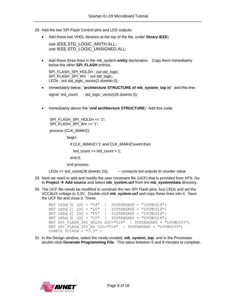
To create the SREC file, we had to open a shell and hand-type an instruction to convert the ELF file to SREC format. This could be cumbersome every time you change your software application. The mb-objcopy command can be added as a post-build step in SDK to automate this process. If you chose to do this, right-click on Tutorial_Test and select C/C++ Build Settings, then select the Build Steps tab. Paste the command into the Post-Build Steps command text box.This will create the SREC file every time the application is built.
Figure 3 - Application Build Settings
The SREC formatted application is now ready to be stored into SPI Flash.
We are using a very simple application for this tutorial but the steps also apply to more complex applications, including interrupt driven applications or OS-based applications.
Create the Boot Loader Application Our main application will be stored in SPI Flash as S-records. We now need a boot loader application to copy the S-records into their correct memory locations. SDK provides a boot loader template which is used for parallel NOR Flash memory. We will use a modified version of the boot loader template to read from SPI Flash using the Xilinx In-System Flash (ISF) library. The library allows the application to use simple commands to communicate with the SPI Flash. The SPI drivers will be used in polled mode. 1. Go to File > New > Xilinx C Project to create a new C project.
2. Select the SREC Bootloader template and change the Project name to SPI_Boot. Click Next.
3. Change the Board Support Package Project name to BSP_with_ISF. Click Finish.
We need to add and configure the ISF library for the BSP.
4. Right-click on the BSP_with_ISF project and select Board Support Package Settings.
Spartan-6 LX9 MicroBoard Tutorial
Page 11 of 18
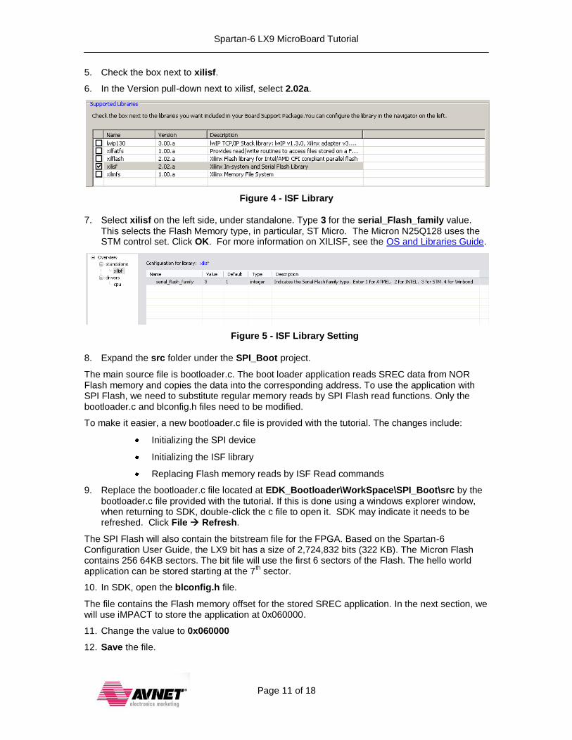
5. Check the box next to xilisf.
6. In the Version pull-down next to xilisf, select 2.02a.
Figure 4 - ISF Library
7. Select xilisf on the left side, under standalone. Type 3 for the serial_Flash_family value.
This selects the Flash Memory type, in particular, ST Micro. The Micron N25Q128 uses the STM control set. Click OK. For more information on XILISF, see the OS and Libraries Guide.
Figure 5 - ISF Library Setting
8. Expand the src folder under the SPI_Boot project.
The main source file is bootloader.c. The boot loader application reads SREC data from NOR Flash memory and copies the data into the corresponding address. To use the application with SPI Flash, we need to substitute regular memory reads by SPI Flash read functions. Only the bootloader.c and blconfig.h files need to be modified.
To make it easier, a new bootloader.c file is provided with the tutorial. The changes include:
Initializing the SPI device
Initializing the ISF library
Replacing Flash memory reads by ISF Read commands
9. Replace the bootloader.c file located at EDK_Bootloader\WorkSpace\SPI_Boot\src by the
bootloader.c file provided with the tutorial. If this is done using a windows explorer window, when returning to SDK, double-click the c file to open it. SDK may indicate it needs to be refreshed. Click File Refresh.
The SPI Flash will also contain the bitstream file for the FPGA. Based on the Spartan-6 Configuration User Guide, the LX9 bit has a size of 2,724,832 bits (322 KB). The Micron Flash contains 256 64KB sectors. The bit file will use the first 6 sectors of the Flash. The hello world application can be stored starting at the 7
th sector.
10. In SDK, open the blconfig.h file.
The file contains the Flash memory offset for the stored SREC application. In the next section, we will use iMPACT to store the application at 0x060000.
11. Change the value to 0x060000
12. Save the file.
Spartan-6 LX9 MicroBoard Tutorial
Page 12 of 18
The boot loader will be located in the MicroBlaze local memory so that it can be embedded in the FPGA BRAMs. After configuration, MicroBlaze will execute the boot loader from its local memory.
13. Right-click on the SPI_Boot project and select Generate Linker Script.
14. Use the drop-down list to select the local memory, microblaze_0_i_bram_ctrl_microblaze_0_d_bram_ctrl, for all the code sections. Click Generate then Yes.
To merge the boot loader code with the internal BRAMs we can run the download step in SDK. The program operation will fail since the board is not connected but a download.bit file will be generated. Another possibility is to run the data2mem application in command line mode.
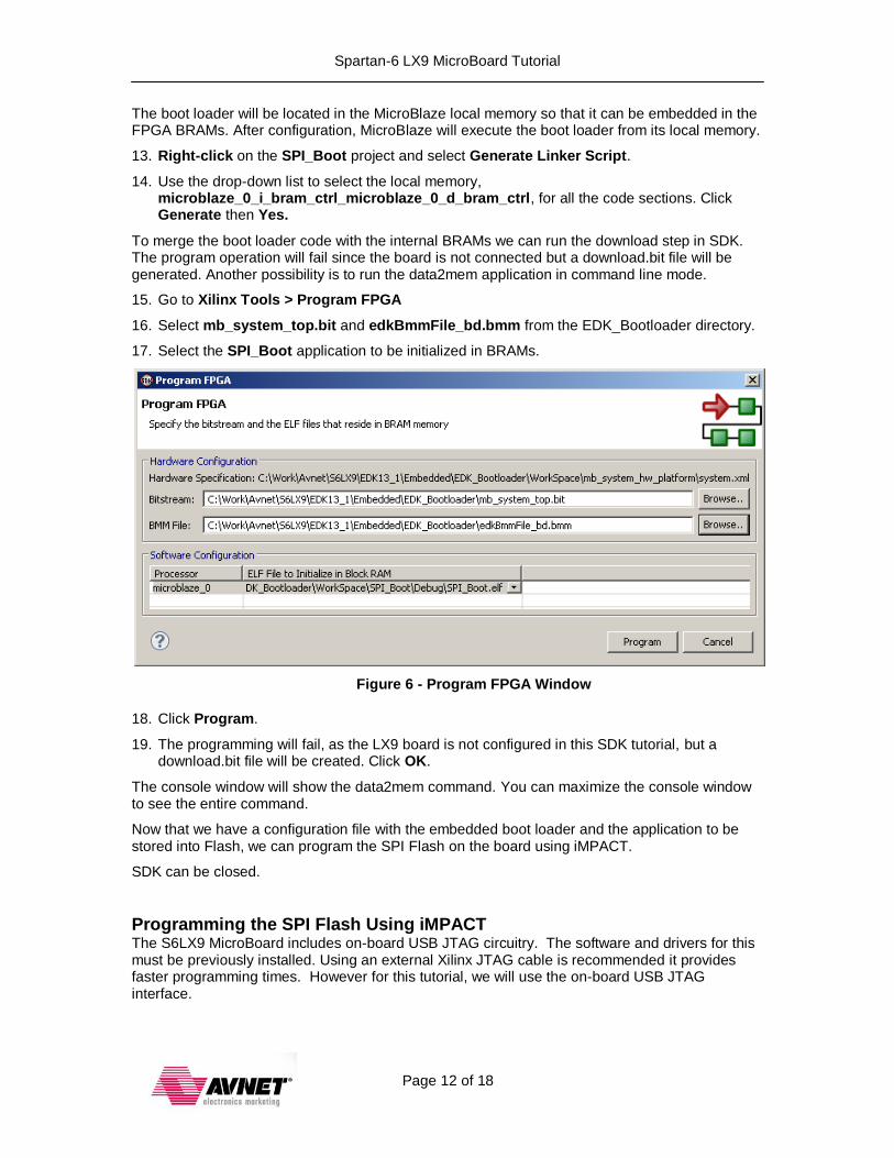
15. Go to Xilinx Tools > Program FPGA
16. Select mb_system_top.bit and edkBmmFile_bd.bmm from the EDK_Bootloader directory.
17. Select the SPI_Boot application to be initialized in BRAMs.
Figure 6 - Program FPGA Window
18. Click Program.
19. The programming will fail, as the LX9 board is not configured in this SDK tutorial, but a download.bit file will be created. Click OK.
The console window will show the data2mem command. You can maximize the console window to see the entire command.
Now that we have a configuration file with the embedded boot loader and the application to be stored into Flash, we can program the SPI Flash on the board using iMPACT.
SDK can be closed.
Programming the SPI Flash Using iMPACT The S6LX9 MicroBoard includes on-board USB JTAG circuitry. The software and drivers for this must be previously installed. Using an external Xilinx JTAG cable is recommended it provides faster programming times. However for this tutorial, we will use the on-board USB JTAG interface.
Spartan-6 LX9 MicroBoard Tutorial
Page 13 of 18
1. Plug the MicroBoard Type A USB into the PC or use the USB Extension to connect between the PC and the board. Once plugged in, the green LED D7 should light to indicate that the power is good.
This tutorial assumes that the Silicon Labs CP2102 USB-to-UART Bridge driver was previously installed. If not, see the Avnet DRC for the LX9 MicroBoard for instructions on installing this driver.
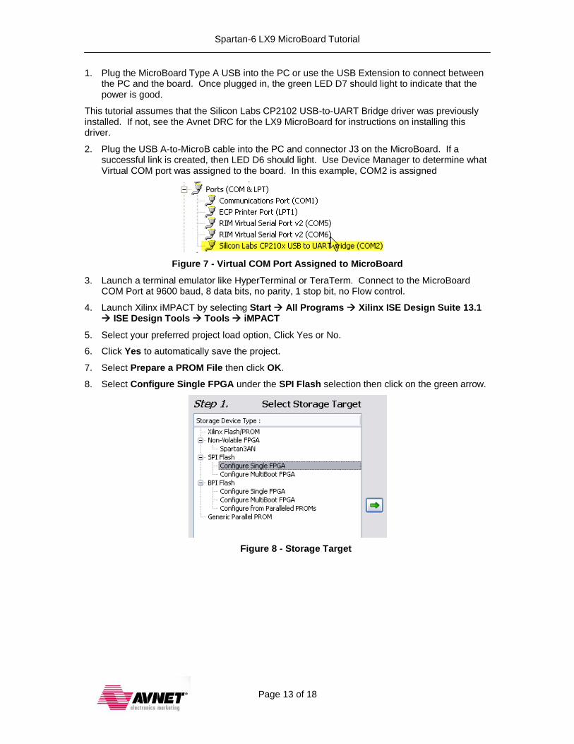
2. Plug the USB A-to-MicroB cable into the PC and connector J3 on the MicroBoard. If a successful link is created, then LED D6 should light. Use Device Manager to determine what Virtual COM port was assigned to the board. In this example, COM2 is assigned
Figure 7 - Virtual COM Port Assigned to MicroBoard
3. Launch a terminal emulator like HyperTerminal or TeraTerm. Connect to the MicroBoard COM Port at 9600 baud, 8 data bits, no parity, 1 stop bit, no Flow control.
4. Launch Xilinx iMPACT by selecting Start All Programs Xilinx ISE Design Suite 13.1 ISE Design Tools Tools iMPACT
5. Select your preferred project load option, Click Yes or No.
6. Click Yes to automatically save the project.
7. Select Prepare a PROM File then click OK.
8. Select Configure Single FPGA under the SPI Flash selection then click on the green arrow.
Figure 8 - Storage Target
Spartan-6 LX9 MicroBoard Tutorial
Page 14 of 18
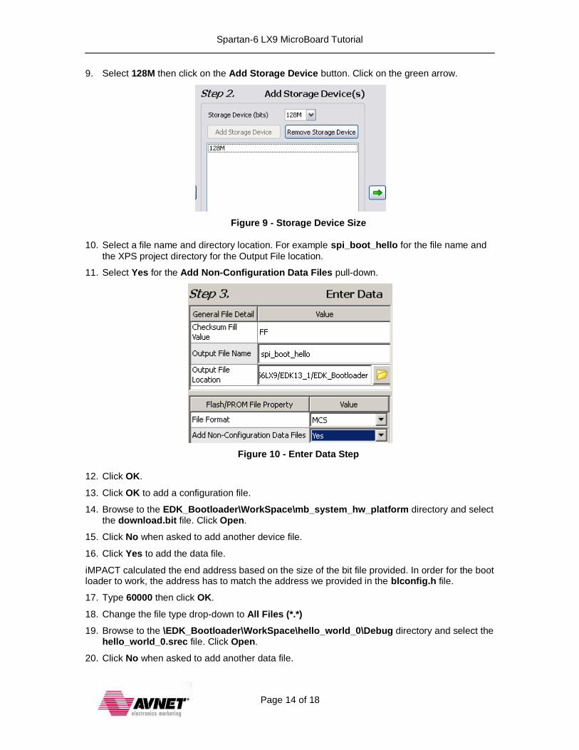
9. Select 128M then click on the Add Storage Device button. Click on the green arrow.
Figure 9 - Storage Device Size
10. Select a file name and directory location. For example spi_boot_hello for the file name and
the XPS project directory for the Output File location.
11. Select Yes for the Add Non-Configuration Data Files pull-down.
Figure 10 - Enter Data Step
12. Click OK.
13. Click OK to add a configuration file.
14. Browse to the EDK_Bootloader\WorkSpace\mb_system_hw_platform directory and select the download.bit file. Click Open.
15. Click No when asked to add another device file.
16. Click Yes to add the data file.
iMPACT calculated the end address based on the size of the bit file provided. In order for the boot loader to work, the address has to match the address we provided in the blconfig.h file.
17. Type 60000 then click OK.
18. Change the file type drop-down to All Files (*.*)
19. Browse to the \EDK_Bootloader\WorkSpace\hello_world_0\Debug directory and select the hello_world_0.srec file. Click Open.
20. Click No when asked to add another data file.
Spartan-6 LX9 MicroBoard Tutorial
Page 15 of 18
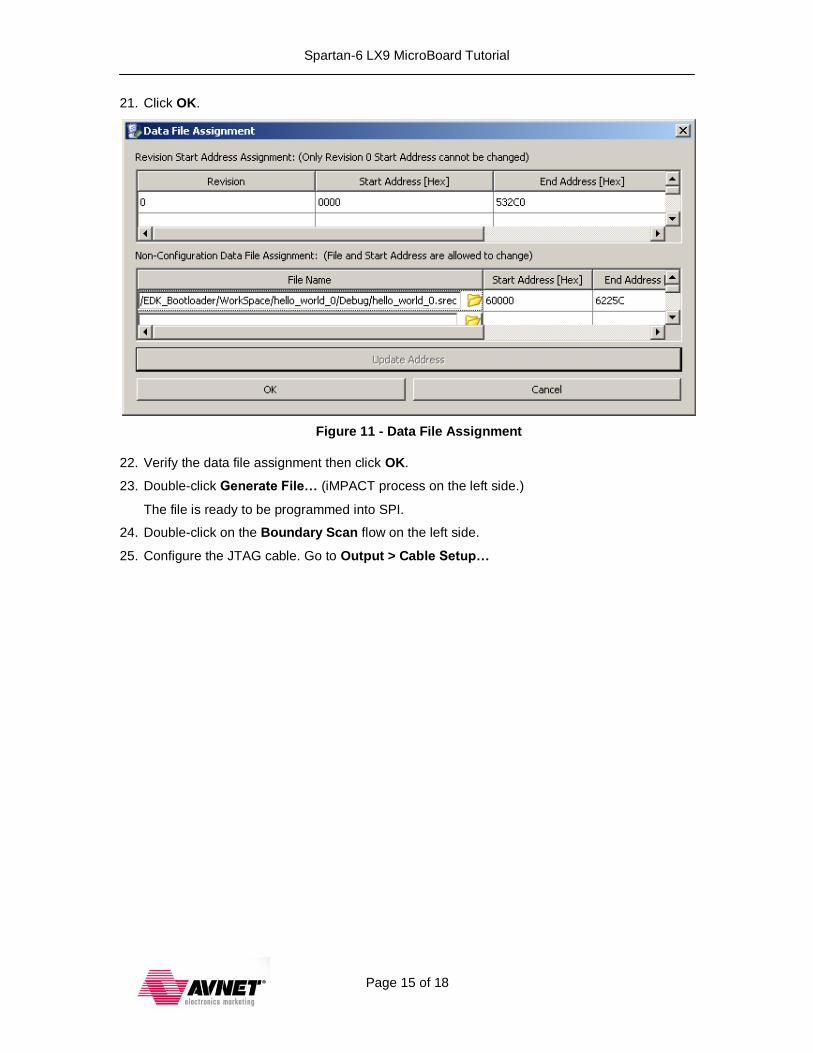
21. Click OK.
Figure 11 - Data File Assignment
22. Verify the data file assignment then click OK.
23. Double-click Generate File… (iMPACT process on the left side.)
The file is ready to be programmed into SPI.
24. Double-click on the Boundary Scan flow on the left side.
25. Configure the JTAG cable. Go to Output > Cable Setup…
Spartan-6 LX9 MicroBoard Tutorial
Page 16 of 18
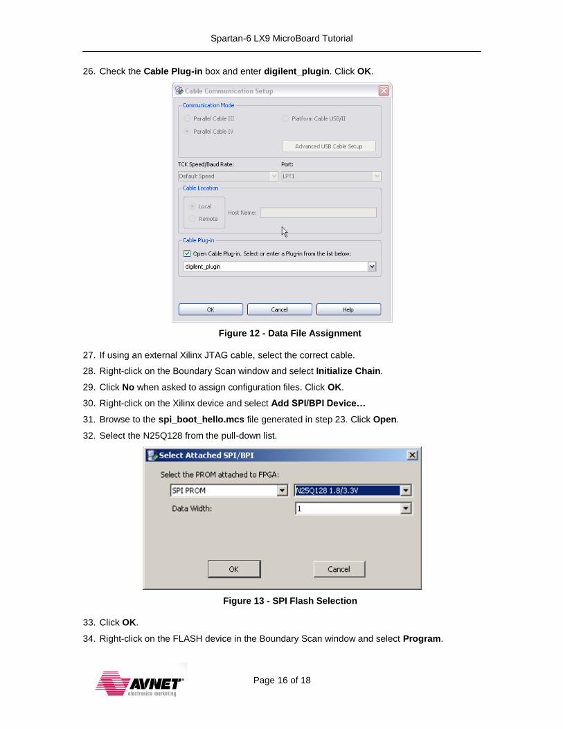
26. Check the Cable Plug-in box and enter digilent_plugin. Click OK.
Figure 12 - Data File Assignment
27. If using an external Xilinx JTAG cable, select the correct cable.
28. Right-click on the Boundary Scan window and select Initialize Chain.
29. Click No when asked to assign configuration files. Click OK.
30. Right-click on the Xilinx device and select Add SPI/BPI Device…
31. Browse to the spi_boot_hello.mcs file generated in step 23. Click Open.
32. Select the N25Q128 from the pull-down list.
Figure 13 - SPI Flash Selection
33. Click OK.
34. Right-click on the FLASH device in the Boundary Scan window and select Program.
Spartan-6 LX9 MicroBoard Tutorial
Page 17 of 18
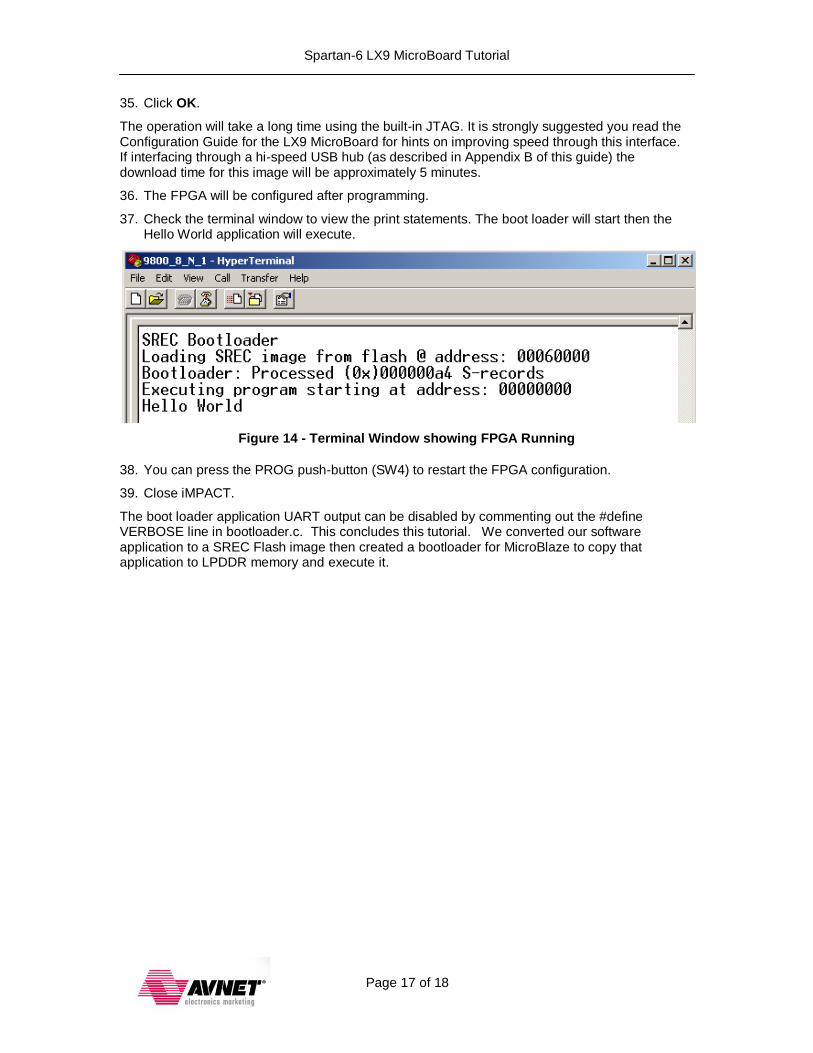
35. Click OK.
The operation will take a long time using the built-in JTAG. It is strongly suggested you read the Configuration Guide for the LX9 MicroBoard for hints on improving speed through this interface. If interfacing through a hi-speed USB hub (as described in Appendix B of this guide) the download time for this image will be approximately 5 minutes.
36. The FPGA will be configured after programming.
37. Check the terminal window to view the print statements. The boot loader will start then the Hello World application will execute.
Figure 14 - Terminal Window showing FPGA Running
38. You can press the PROG push-button (SW4) to restart the FPGA configuration.
39. Close iMPACT.
The boot loader application UART output can be disabled by commenting out the #define VERBOSE line in bootloader.c. This concludes this tutorial. We converted our software application to a SREC Flash image then created a bootloader for MicroBlaze to copy that application to LPDDR memory and execute it.
Spartan-6 LX9 MicroBoard Tutorial
Page 18 of 18
Getting Help and Support
Evaluation Kit home page with Documentation and Reference Designs http://em.avnet.com/s6microboard Avnet Spartan-6 LX9 MicroBoard forum: http://community.em.avnet.com/t5/Spartan-6-LX9-MicroBoard/bd-p/Spartan-6LX9MicroBoard
For Xilinx technical support, you may contact your local Avnet/Silica FAE or Xilinx Online Technical Support at www.support.xilinx.com. On this site you will also find the following resources for assistance:
Software, IP, and Documentation Updates
Access to Technical Support Web Tools
Searchable Answer Database with Over 4,000 Solutions
User Forums
Training - Select instructor-led classes and recorded e-learning options Contact Avnet Support for any questions regarding the Spartan-6 LX9 MicroBoard reference designs, kit hardware, or if you are interested in designing any of the kit devices into your next design.
http://www.em.avnet.com/techsupport You can also contact your local Avnet/Silica FAE.