Embed Size (px)
Citation preview
Educational Product
Teachers Grades K-12
EG-2000-10-64-MSFC
NASA Spacelink
Optics: Light, Color, and Their Uses–An EducatorsGuide With Activities In Science and Mathematics isavailable in electronic format through NASA Spacelink–one of the Agency’s electronic resources specificallydeveloped for use by the educational community.
The system may be accessed at the following address:http://spacelink.nasa.gov
iOptics: An Educator’s Guide With Activities in Science and Mathematics EG-2000-10-64-MSFC
Optics:Light, Color, and Their Uses
National Aeronautics and Space Administration
Space Optics Manufacturing Technology CenterMarshall Space Flight Center
Customer Employee Relations Directorate /Education Programs Department
Marshall Space Flight Center
This publication is in the Public Domain and is not protected by copyright.Permission is not required for duplication.
EG-2000-10-64-MSFC
An Educator’s Guide With Activities in Science and Mathematics
Lig
ht, C
olor, and
Th
eir Uses

Optics: An Educator’s Guide With Activities in Science and Mathematics EG-2000-10-64-MSFCii
Lig
ht,
Col
or, a
nd
Th
eir
Use
s
iiiOptics: An Educator’s Guide With Activities in Science and Mathematics EG-2000-10-64-MSFC
Optics: Light, Color, and Their Uses
An Educator’s GuideWith Activities in Science and Mathematics
Lig
ht, C
olor, and
Th
eir Uses
Acknowledgments
Pat ArmstrongCurriculum Development CoordinatorHuntsville City SchoolsHuntsville, AL
P. Derryl EvansOptical PhysicistRetired from NASA Marshall SpaceFlight CenterHuntsville, AL
Vinson B. HuegeleOptical PhysicistSpace Optics ManufacturingTechnology CenterNASA Marshall Space Flight Center
Era Jean MannComputer SpecialistRetired from NASA Marshall SpaceFlight CenterHuntsville, AL
Vicki SmithIPA/Huntsville City SchoolsEducation Program SpecialistNASA Marshall Space Flight CenterHuntsville, AL
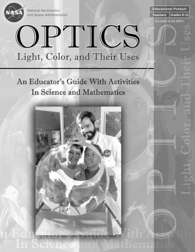
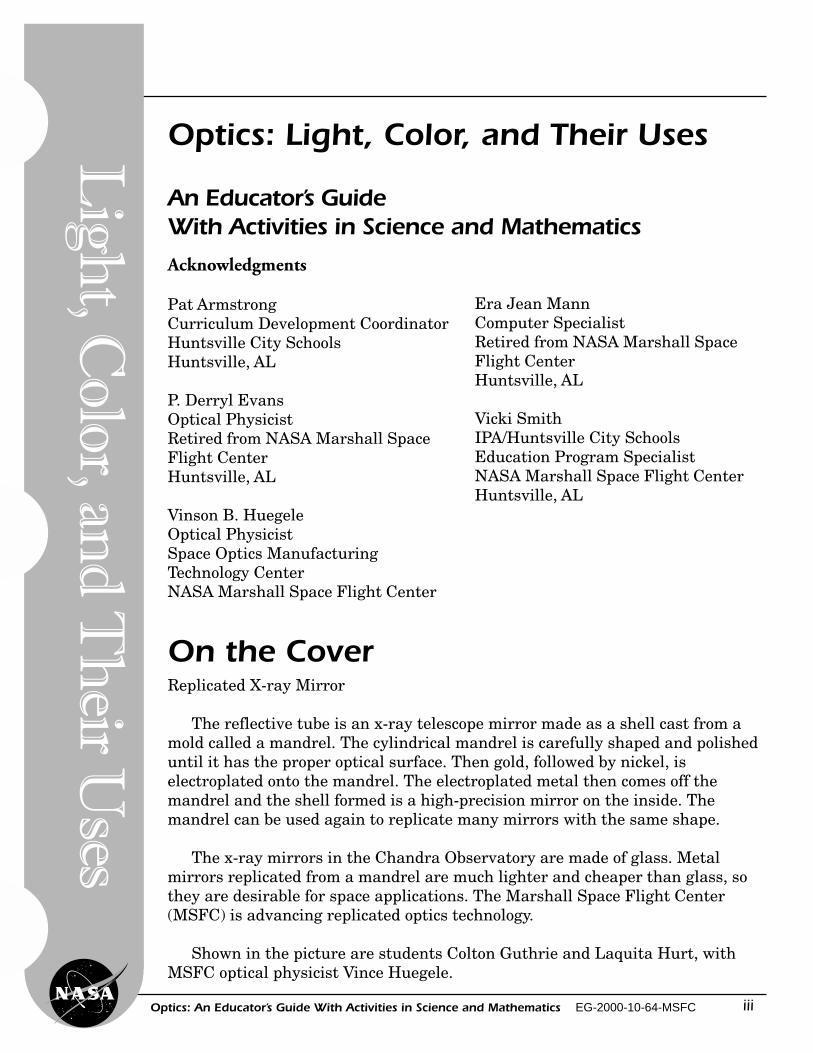
Replicated X-ray Mirror
The reflective tube is an x-ray telescope mirror made as a shell cast from amold called a mandrel. The cylindrical mandrel is carefully shaped and polisheduntil it has the proper optical surface. Then gold, followed by nickel, iselectroplated onto the mandrel. The electroplated metal then comes off themandrel and the shell formed is a high-precision mirror on the inside. Themandrel can be used again to replicate many mirrors with the same shape.
The x-ray mirrors in the Chandra Observatory are made of glass. Metalmirrors replicated from a mandrel are much lighter and cheaper than glass, sothey are desirable for space applications. The Marshall Space Flight Center(MSFC) is advancing replicated optics technology.
Shown in the picture are students Colton Guthrie and Laquita Hurt, withMSFC optical physicist Vince Huegele.
On the Cover
Optics: An Educator’s Guide With Activities in Science and Mathematics EG-2000-10-64-MSFCiv
Lig
ht,
Col
or, a
nd
Th
eir
Use
s
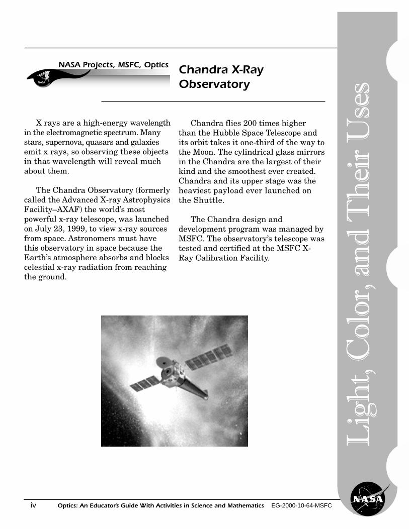
X rays are a high-energy wavelengthin the electromagnetic spectrum. Manystars, supernova, quasars and galaxiesemit x rays, so observing these objectsin that wavelength will reveal muchabout them.
The Chandra Observatory (formerlycalled the Advanced X-ray AstrophysicsFacility–AXAF) the world’s mostpowerful x-ray telescope, was launchedon July 23, 1999, to view x-ray sourcesfrom space. Astronomers must havethis observatory in space because theEarth’s atmosphere absorbs and blockscelestial x-ray radiation from reachingthe ground.
NASA
NASA Projects, MSFC, Optics Chandra X-RayObservatory
Chandra flies 200 times higherthan the Hubble Space Telescope andits orbit takes it one-third of the way tothe Moon. The cylindrical glass mirrorsin the Chandra are the largest of theirkind and the smoothest ever created.Chandra and its upper stage was theheaviest payload ever launched onthe Shuttle.
The Chandra design anddevelopment program was managed byMSFC. The observatory’s telescope wastested and certified at the MSFC X-Ray Calibration Facility.
vOptics: An Educator’s Guide With Activities in Science and Mathematics EG-2000-10-64-MSFC
Lig
ht, C
olor, and
Th
eir Uses
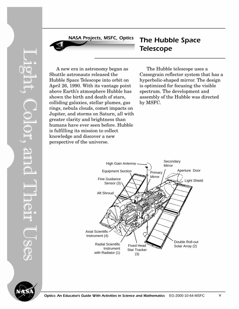
A new era in astronomy began asShuttle astronauts released theHubble Space Telescope into orbit onApril 26, 1990. With its vantage pointabove Earth’s atmosphere Hubble hasshown the birth and death of stars,colliding galaxies, stellar plumes, gasrings, nebula clouds, comet impacts onJupiter, and storms on Saturn, all withgreater clarity and brightness thanhumans have ever seen before. Hubbleis fulfilling its mission to collectknowledge and discover a newperspective of the universe.
Aft Shroud
Double Roll-outSolar Array (2)
PrimaryMirror
SecondaryMirror
Aperture Door
Light Shield
Axial ScientificInstrument (4)
Radial ScientificInstrument
with Radiator (1)
Fixed HeadStar Tracker
(3)
High Gain Antenna
Equipment Section
Fine GuidanceSensor (3)
The Hubble telescope uses aCassegrain reflector system that has ahyperbolic-shaped mirror. The designis optimized for focusing the visiblespectrum. The development andassembly of the Hubble was directedby MSFC.
NASA
NASA Projects, MSFC, Optics The Hubble SpaceTelescope
Optics: An Educator’s Guide With Activities in Science and Mathematics EG-2000-10-64-MSFCvi
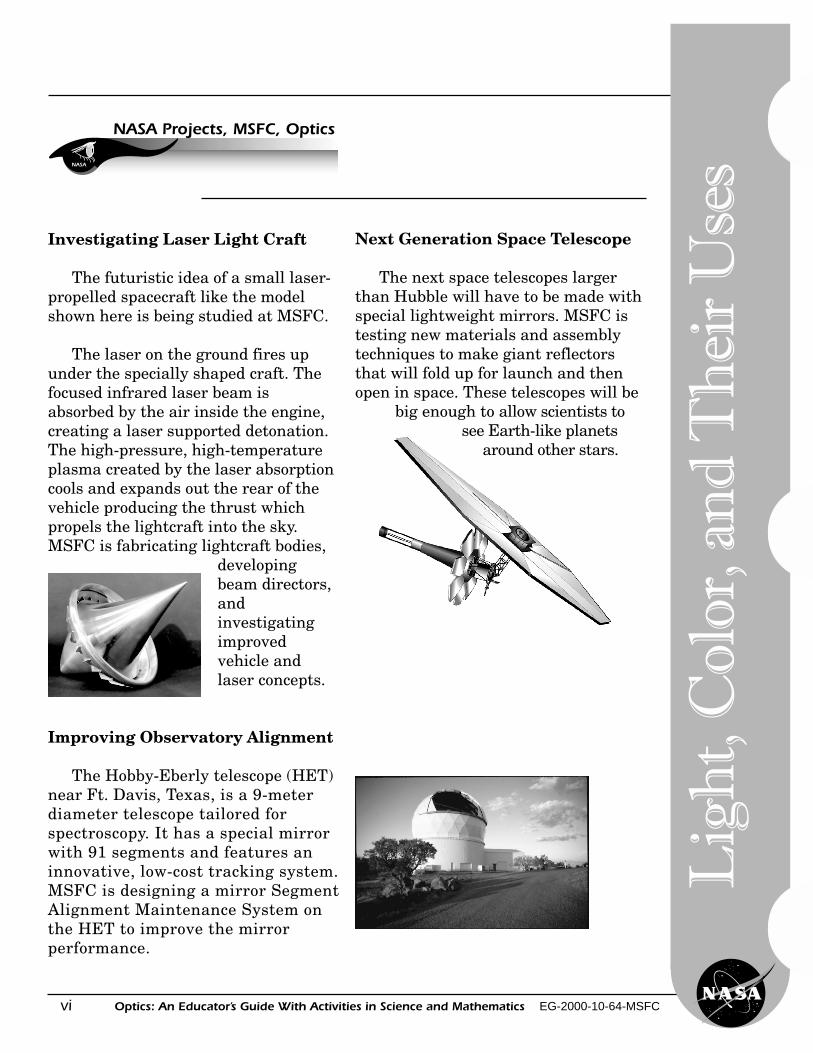
Investigating Laser Light Craft
The futuristic idea of a small laser-propelled spacecraft like the modelshown here is being studied at MSFC.
The laser on the ground fires upunder the specially shaped craft. Thefocused infrared laser beam isabsorbed by the air inside the engine,creating a laser supported detonation.The high-pressure, high-temperatureplasma created by the laser absorptioncools and expands out the rear of thevehicle producing the thrust whichpropels the lightcraft into the sky.MSFC is fabricating lightcraft bodies,
developingbeam directors,andinvestigatingimprovedvehicle andlaser concepts.
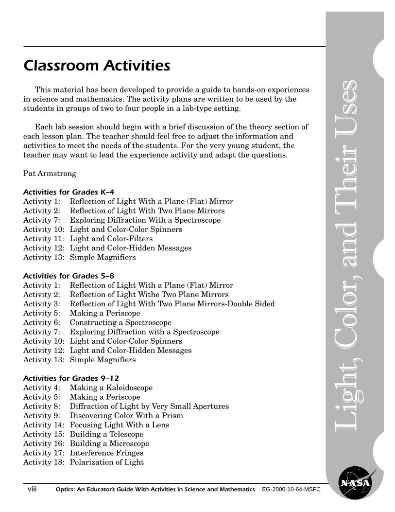
Improving Observatory Alignment
The Hobby-Eberly telescope (HET)near Ft. Davis, Texas, is a 9-meterdiameter telescope tailored forspectroscopy. It has a special mirrorwith 91 segments and features aninnovative, low-cost tracking system.MSFC is designing a mirror SegmentAlignment Maintenance System onthe HET to improve the mirrorperformance.
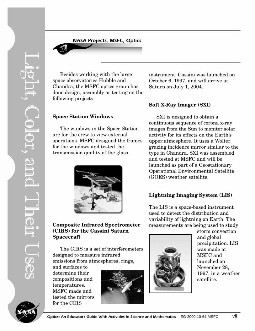
Next Generation Space Telescope
The next space telescopes largerthan Hubble will have to be made withspecial lightweight mirrors. MSFC istesting new materials and assemblytechniques to make giant reflectorsthat will fold up for launch and thenopen in space. These telescopes will be
big enough to allow scientists tosee Earth-like planets
around other stars.
NASA
NASA Projects, MSFC, Optics
Lig
ht,
Col
or, a
nd
Th
eir
Use
s
viiOptics: An Educator’s Guide With Activities in Science and Mathematics EG-2000-10-64-MSFC
Lig
ht, C
olor, and
Th
eir Uses
Besides working with the largespace observatories Hubble andChandra, the MSFC optics group hasdone design, assembly or testing on thefollowing projects.
Space Station Windows
The windows in the Space Stationare for the crew to view externaloperations. MSFC designed the framesfor the windows and tested thetransmission quality of the glass.
Composite Infrared Spectrometer(CIRS) for the Cassini SaturnSpacecraft
The CIRS is a set of interferometersdesigned to measure infraredemissions from atmospheres, rings,and surfaces todetermine theircompositions andtemperatures.MSFC made andtested the mirrorsfor the CIRS
NASA
NASA Projects, MSFC, Optics
instrument. Cassini was launched onOctober 6, 1997, and will arrive atSaturn on July 1, 2004.
Soft X-Ray Imager (SXI)
SXI is designed to obtain acontinuous sequence of corona x-rayimages from the Sun to monitor solaractivity for its effects on the Earth’supper atmosphere. It uses a Woltergrazing incidence mirror similar to thetype in Chandra. SXI was assembledand tested at MSFC and will belaunched as part of a GeostationaryOperational Environmental Satellite(GOES) weather satellite.
Lightning Imaging System (LIS)
The LIS is a space-based instrumentused to detect the distribution andvariability of lightning on Earth. Themeasurements are being used to study
storm convectionand globalprecipitation. LISwas made atMSFC andlaunched onNovember 28,1997, in a weathersatellite.
Optics: An Educator’s Guide With Activities in Science and Mathematics EG-2000-10-64-MSFCviii
Lig
ht,
Col
or, a
nd
Th
eir
Use
s
Classroom ActivitiesThis material has been developed to provide a guide to hands-on experiences
in science and mathematics. The activity plans are written to be used by thestudents in groups of two to four people in a lab-type setting.
Each lab session should begin with a brief discussion of the theory section ofeach lesson plan. The teacher should feel free to adjust the information andactivities to meet the needs of the students. For the very young student, theteacher may want to lead the experience activity and adapt the questions.
Pat Armstrong
Activities for Grades K–4Activity 1: Reflection of Light With a Plane (Flat) MirrorActivity 2: Reflection of Light With Two Plane MirrorsActivity 7: Exploring Diffraction With a SpectroscopeActivity 10: Light and Color-Color SpinnersActivity 11: Light and Color-FiltersActivity 12: Light and Color-Hidden MessagesActivity 13: Simple Magnifiers
Activities for Grades 5–8Activity 1: Reflection of Light With a Plane (Flat) MirrorActivity 2: Reflection of Light Withe Two Plane MirrorsActivity 3: Reflection of Light With Two Plane Mirrors-Double SidedActivity 5: Making a PeriscopeActivity 6: Constructing a SpectroscopeActivity 7: Exploring Diffraction with a SpectroscopeActivity 10: Light and Color-Color SpinnersActivity 12: Light and Color-Hidden MessagesActivity 13: Simple Magnifiers
Activities for Grades 9–12Activity 4: Making a KaleidoscopeActivity 5: Making a PeriscopeActivity 8: Diffraction of Light by Very Small AperturesActivity 9: Discovering Color With a PrismActivity 14: Focusing Light With a LensActivity 15: Building a TelescopeActivity 16: Building a MicroscopeActivity 17: Interference FringesActivity 18: Polarization of Light
ixOptics: An Educator’s Guide With Activities in Science and Mathematics EG-2000-10-64-MSFC
Table of ContentsLight, Color, and Their Uses
Activity / Lesson
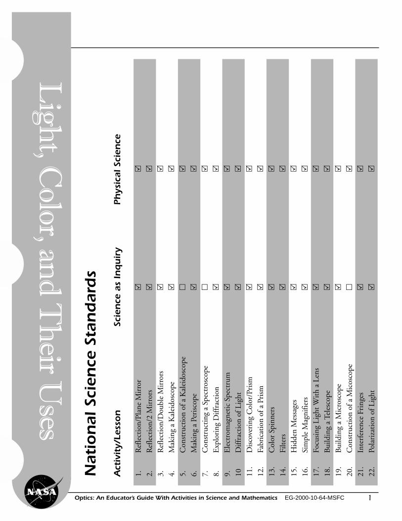
National Science Standards .................................................................. 1
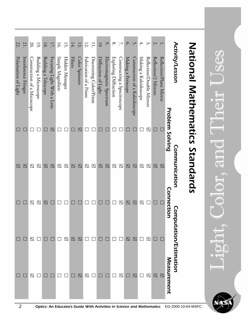
National Mathematics Standards ........................................................ 2
Introduction to Light and Color ............................................................ 3
Introduction to Mirors and Lenses ....................................................... 5
1 Reflection of Light With a Plane (Flat) Mirror—Trace a Star ........... 13
2 Reflection of Light With Two Plane Mirrors — Double Mirrors
Placed at a 90-Degree Angle ............................................................ 17
3 Reflection of Light With Two Plane Mirrors—Double Mirrors
Placed at a Number of Angles ......................................................... 19
4 Making a Kaleidoscope.......................................................................... 23
Construction of a Large Kaleidoscope Using PVC Pipe ...................... 25
5 Making a Periscope ............................................................................... 27
6 Constructing a Spectroscope ................................................................. 29
7 Exploring Diffraction With a Spectroscope .......................................... 31
The Electromagnetic Spectrum ............................................................ 34
8 Diffraction of Light by Very Small Apertures...................................... 35
9 Discovering Color With a Prism ........................................................... 37
Fabrication of a Prism From Acrylic Plastic ........................................ 40
10 Light and Color — Color Spinners ........................................................ 41
11 Light and Color — Filters ...................................................................... 43
12 Light and Color—Hidden Messages .................................................... 45
13 Simple Magnifiers ................................................................................. 47
14 Focusing Light With a Lens .................................................................. 49
15 Building a Telescope.............................................................................. 53
Diagrams of Reflector and Refractor Telescopes ................................. 56
16 Building a Microscope ............................................................................ 57
Construction of a Microscope — A File Folder Microscope ................... 59
17 Interference Fringes ............................................................................... 61
18 Polarization of Light ............................................................................... 63
Lig
ht, C
olor, and
Th
eir Uses
Optics: An Educator’s Guide With Activities in Science and Mathematics EG-2000-10-64-MSFCx
Lig
ht,
Col
or, a
nd
Th
eir
Use
sTeachers’ Resource Materials ................................................................ 65
Answer Booklet ................................................................................. 65
Glossary ............................................................................................. 73
General Information for Educators and Students........................... 77
NASA Online Educational Resources .............................................. 79
Education Home Page ................................................................. 79
NASA Spacelink .......................................................................... 79
Educator Resource Center and CORE........................................ 80
NASA Television (NTV) .............................................................. 81
List Of Catalogs ................................................................................ 82
Educator Reply Card......................................................................... 83
1Optics: An Educator’s Guide With Activities in Science and Mathematics EG-2000-10-64-MSFC
Lig
ht, C
olor, and
Th
eir Uses
Nat
ion
al S
cien
ce S
tan
dar
ds
Act
ivit
y/Le
sson
Scie
nce
as
Inquir
yPh
ysic
al S
cien
ce
1.R
efle
ctio
n/Pl
ane
Mir
ror
��
2.R
efle
ctio
n/2
Mir
rors
��
3.R
efle
ctio
n/D
oubl
e M
irro
rs�
�
4.M
akin
g a
Kal
eido
scop
e�
�
5.C
onst
ruct
ion
of a
Kal
eido
scop
e�
�
6.M
akin
g a
Peri
scop
e�
�
7.C
onst
ruct
ing
a Sp
ectr
osco
pe�
�
8.E
xplo
ring
Diff
ract
ion
��
9.E
lect
rom
agne
tic
Spec
trum
��
10D
iffra
ctio
n of
Lig
ht�
�
11.
Dis
cove
ring
Col
or/P
rism
��
12.
Fabr
icat
ion
of a
Pri
sm�
�
13.
Col
or S
pinn
ers
��
14.
Filte
rs�
�
15.
Hid
den
Mes
sage
s�
�
16.
Sim
ple
Mag
nifie
rs�
�
17.
Focu
sing
Lig
ht W
ith
a Le
ns�
�
18.
Bui
ldin
g a
Tele
scop
e�
�
19.
Bui
ldin
g a
Mic
rosc
ope
��
20.
Con
stru
ctio
n of
a M
icos
cope
��
21.
Inte
rfer
ence
Fri
nges
��
22.
Pola
riza
tion
of L
ight
��
2
Lig
ht,
Col
or, a
nd
Th
eir
Use
s
Optics: An Educator’s Guide With Activities in Science and Mathematics EG-2000-10-64-MSFC
Natio
nal M
athem
atics Stand
ar ds
Activity/Lesso
nC
om
mun
ication
Com
putatio
n/E
stimatio
nPro
blem
Solvin
gC
on
nectio
nM
easurem
ent
1.R
eflection/Plane Mirror
��
��
�
2.R
eflection/2 Mirrors
��
��
�
3.R
eflection/Double M
irrors�
��
��
4.M
aking a Kaleidoscope
��
��
�
5.C
onstruction of a Kaleidoscope
��
��
�
6.M
aking a Periscope�
��
��
7.C
onstructing a Spectroscope�
��
��
8.E
xploring Diffraction
��
��
�
9.E
lectromagnetic Spectrum
��
��
�
10D
iffraction of Light�
��
��
11.D
iscovering Color/Prism
��
��
�
12.Fabrication of a Prism
��
��
�
13.C
olor Spinners�
��
��
14.Filters
��
��
�
15.H
idden Messages
��
��
�
16.Sim
ple Magnifiers
��
��
�
17.Focusing Light W
ith a Lens�
��
��
18.B
uilding a Telescope�
��
��
19.B
uilding a Microscope
��
��
�
20.C
onstruction of a Micoscope
��
��
�
21.Interference Fringes
��
��
�
22.Polarization of Light
��
��
�
3Optics: An Educator’s Guide With Activities in Science and Mathematics EG-2000-10-64-MSFC
Introduction to Light and Color
Introduction to Light
Light is a form of radiant energyor energy that travels in waves. SinceGreek times, scientists have debatedthe nature of light. Physicists nowrecognize that light sometimesbehaves like waves and, at other times,like particles. When moving from placeto place, light acts like a system ofwaves. In empty space, light has afixed speed and the wavelength can bemeasured. In the past 300 years,scientists have improved the way theymeasure the speed of light, and theyhave determined that it travels atnearly 299,792 kilometers, or 186,281miles, per second.
When we talk about light, we usuallymean any radiation that we can see.These wavelengths range from about16/1,000,000 of an inchto 32/1,000,000 of an inch. There areother kinds of radiation such asultraviolet light and infrared light, buttheir wavelengths are shorteror longer than the visible lightwavelengths.
When light hits some form ofmatter, it behaves in different ways.When it strikes an opaque object, itmakes a shadow, but light does bendaround obstacles. The bending of lightaround edges or around small slits iscalled diffraction and makes patternsof bands or fringes.
All light can be traced to certainenergy sources, like the Sun, anelectric bulb, or a match, but mostof what hits the eye is reflected light.When light strikes some materials,it is bounced off or reflected. If thematerial is not opaque, the light goesthrough it at a slower speed, and itis bent or refracted. Some light isabsorbed into the material andchanged into other forms of energy,usually heat energy. The light wavesmake the electrons in the materialsvibrate and this kinetic energy ormovement energy makes heat. Frictionof the moving electrons makes heat.
Lig
ht, C
olor, and
Th
eir Uses
4
Lig
ht,
Col
or, a
nd
Th
eir
Use
s
Optics: An Educator’s Guide With Activities in Science and Mathematics EG-2000-10-64-MSFC
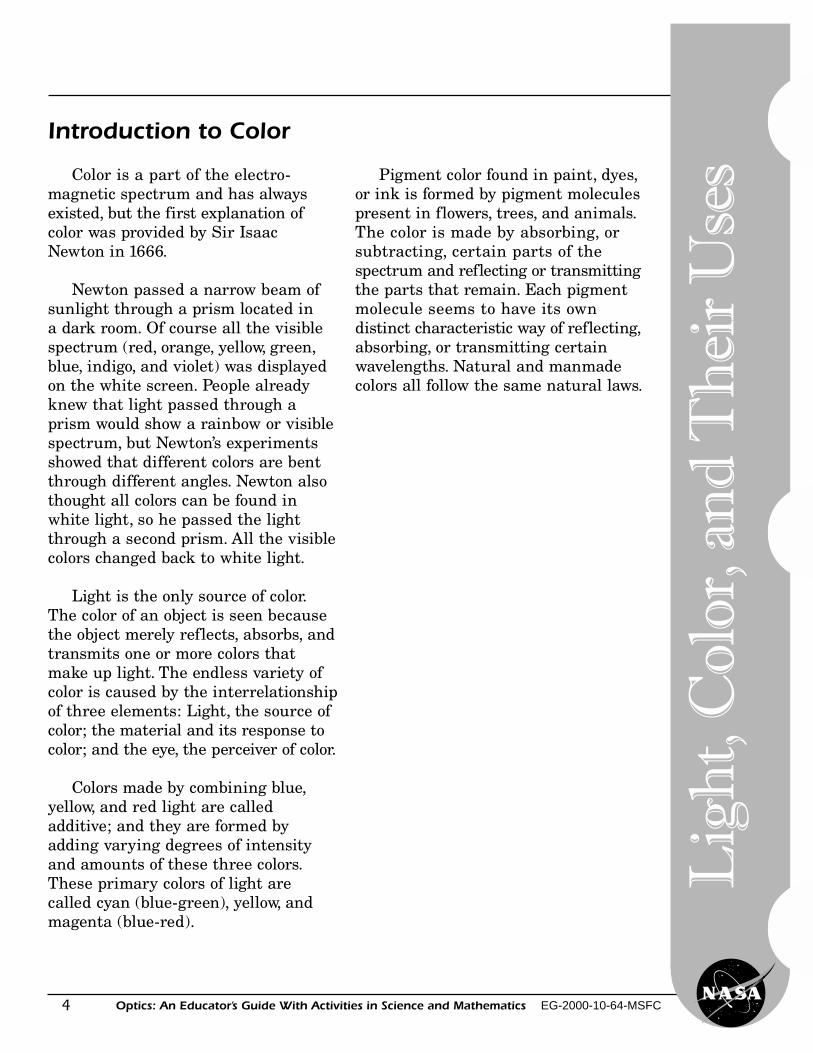
Introduction to Color
Color is a part of the electro-magnetic spectrum and has alwaysexisted, but the first explanation ofcolor was provided by Sir IsaacNewton in 1666.
Newton passed a narrow beam ofsunlight through a prism located ina dark room. Of course all the visiblespectrum (red, orange, yellow, green,blue, indigo, and violet) was displayedon the white screen. People alreadyknew that light passed through aprism would show a rainbow or visiblespectrum, but Newton’s experimentsshowed that different colors are bentthrough different angles. Newton alsothought all colors can be found inwhite light, so he passed the lightthrough a second prism. All the visiblecolors changed back to white light.
Light is the only source of color.The color of an object is seen becausethe object merely reflects, absorbs, andtransmits one or more colors thatmake up light. The endless variety ofcolor is caused by the interrelationshipof three elements: Light, the source ofcolor; the material and its response tocolor; and the eye, the perceiver of color.
Colors made by combining blue,yellow, and red light are calledadditive; and they are formed byadding varying degrees of intensityand amounts of these three colors.These primary colors of light arecalled cyan (blue-green), yellow, andmagenta (blue-red).
Pigment color found in paint, dyes,or ink is formed by pigment moleculespresent in flowers, trees, and animals.The color is made by absorbing, orsubtracting, certain parts of thespectrum and reflecting or transmittingthe parts that remain. Each pigmentmolecule seems to have its owndistinct characteristic way of reflecting,absorbing, or transmitting certainwavelengths. Natural and manmadecolors all follow the same natural laws.
5Optics: An Educator’s Guide With Activities in Science and Mathematics EG-2000-10-64-MSFC
Introduction to Mirrors
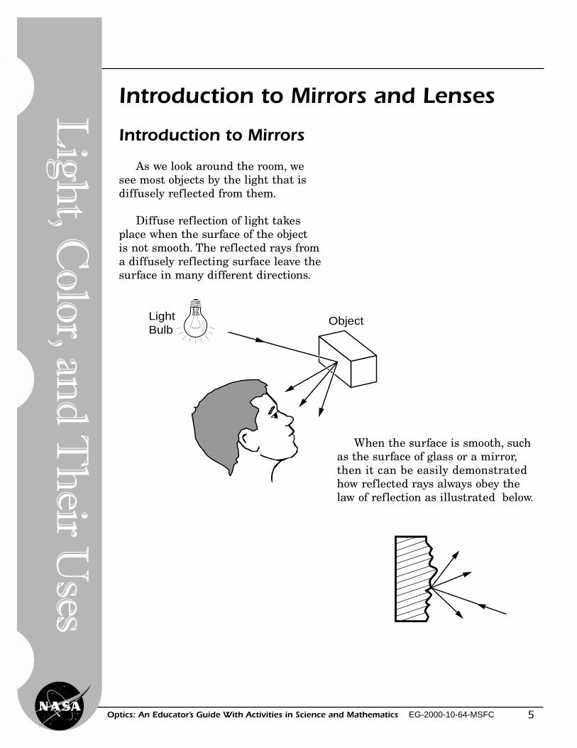
As we look around the room, wesee most objects by the light that isdiffusely reflected from them.
Diffuse reflection of light takesplace when the surface of the objectis not smooth. The reflected rays froma diffusely reflecting surface leave thesurface in many different directions.
LightBulb
Object
Introduction to Mirrors and Lenses
When the surface is smooth, suchas the surface of glass or a mirror,then it can be easily demonstratedhow reflected rays always obey thelaw of reflection as illustrated below.
Lig
ht, C
olor, and
Th
eir Uses
6
Lig
ht,
Col
or, a
nd
Th
eir
Use
s
Optics: An Educator’s Guide With Activities in Science and Mathematics EG-2000-10-64-MSFC
Mirror
Image of Object(Virtual Image)
Object
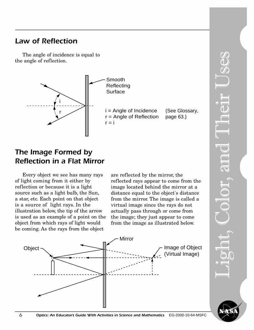
Law of Reflection
The angle of incidence is equal tothe angle of reflection.
The Image Formed byReflection in a Flat Mirror
Every object we see has many raysof light coming from it either byreflection or because it is a lightsource such as a light bulb, the Sun,a star, etc. Each point on that objectis a source of light rays. In theillustration below, the tip of the arrowis used as an example of a point on theobject from which rays of light wouldbe coming. As the rays from the object
SmoothReflectingSurface
i = Angle of Incidencer = Angle of Reflectionr = i
i
r (See Glossary,page 63.)
are reflected by the mirror, thereflected rays appear to come from theimage located behind the mirror at adistance equal to the object's distancefrom the mirror. The image is called avirtual image since the rays do notactually pass through or come fromthe image; they just appear to comefrom the image as illustrated below.
7Optics: An Educator’s Guide With Activities in Science and Mathematics EG-2000-10-64-MSFC
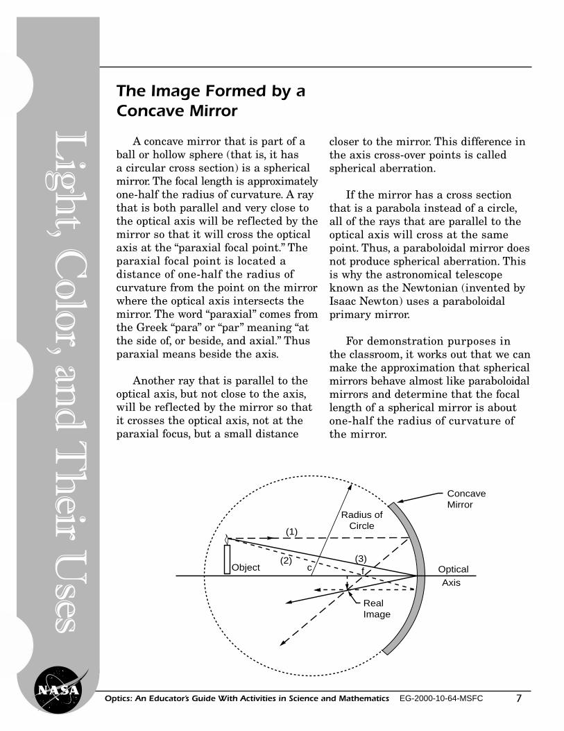
The Image Formed by aConcave Mirror
A concave mirror that is part of aball or hollow sphere (that is, it hasa circular cross section) is a sphericalmirror. The focal length is approximatelyone-half the radius of curvature. A raythat is both parallel and very close tothe optical axis will be reflected by themirror so that it will cross the opticalaxis at the “paraxial focal point.” Theparaxial focal point is located adistance of one-half the radius ofcurvature from the point on the mirrorwhere the optical axis intersects themirror. The word “paraxial” comes fromthe Greek “para” or “par” meaning “atthe side of, or beside, and axial.” Thusparaxial means beside the axis.
Another ray that is parallel to theoptical axis, but not close to the axis,will be reflected by the mirror so thatit crosses the optical axis, not at theparaxial focus, but a small distance
ConcaveMirror
RealImage
Object(2)
(1)
c
Radius ofCircle
(3)f Optical
Axis
closer to the mirror. This difference inthe axis cross-over points is calledspherical aberration.
If the mirror has a cross sectionthat is a parabola instead of a circle,all of the rays that are parallel to theoptical axis will cross at the samepoint. Thus, a paraboloidal mirror doesnot produce spherical aberration. Thisis why the astronomical telescopeknown as the Newtonian (invented byIsaac Newton) uses a paraboloidalprimary mirror.
For demonstration purposes inthe classroom, it works out that we canmake the approximation that sphericalmirrors behave almost like paraboloidalmirrors and determine that the focallength of a spherical mirror is aboutone-half the radius of curvature ofthe mirror.
Lig
ht, C
olor, and
Th
eir Uses
8
Lig
ht,
Col
or, a
nd
Th
eir
Use
s
Optics: An Educator’s Guide With Activities in Science and Mathematics EG-2000-10-64-MSFC
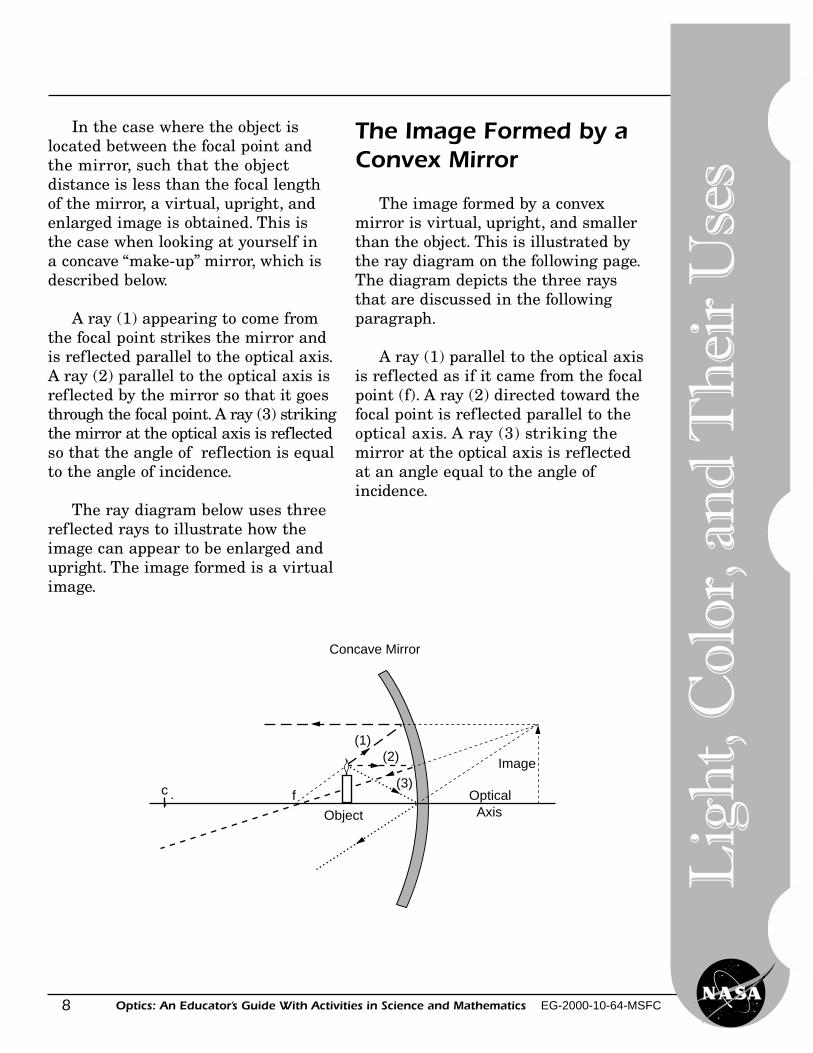
In the case where the object islocated between the focal point andthe mirror, such that the objectdistance is less than the focal lengthof the mirror, a virtual, upright, andenlarged image is obtained. This isthe case when looking at yourself ina concave “make-up” mirror, which isdescribed below.
A ray (1) appearing to come fromthe focal point strikes the mirror andis reflected parallel to the optical axis.A ray (2) parallel to the optical axis isreflected by the mirror so that it goesthrough the focal point. A ray (3) strikingthe mirror at the optical axis is reflectedso that the angle of reflection is equalto the angle of incidence.
The ray diagram below uses threereflected rays to illustrate how theimage can appear to be enlarged andupright. The image formed is a virtualimage.
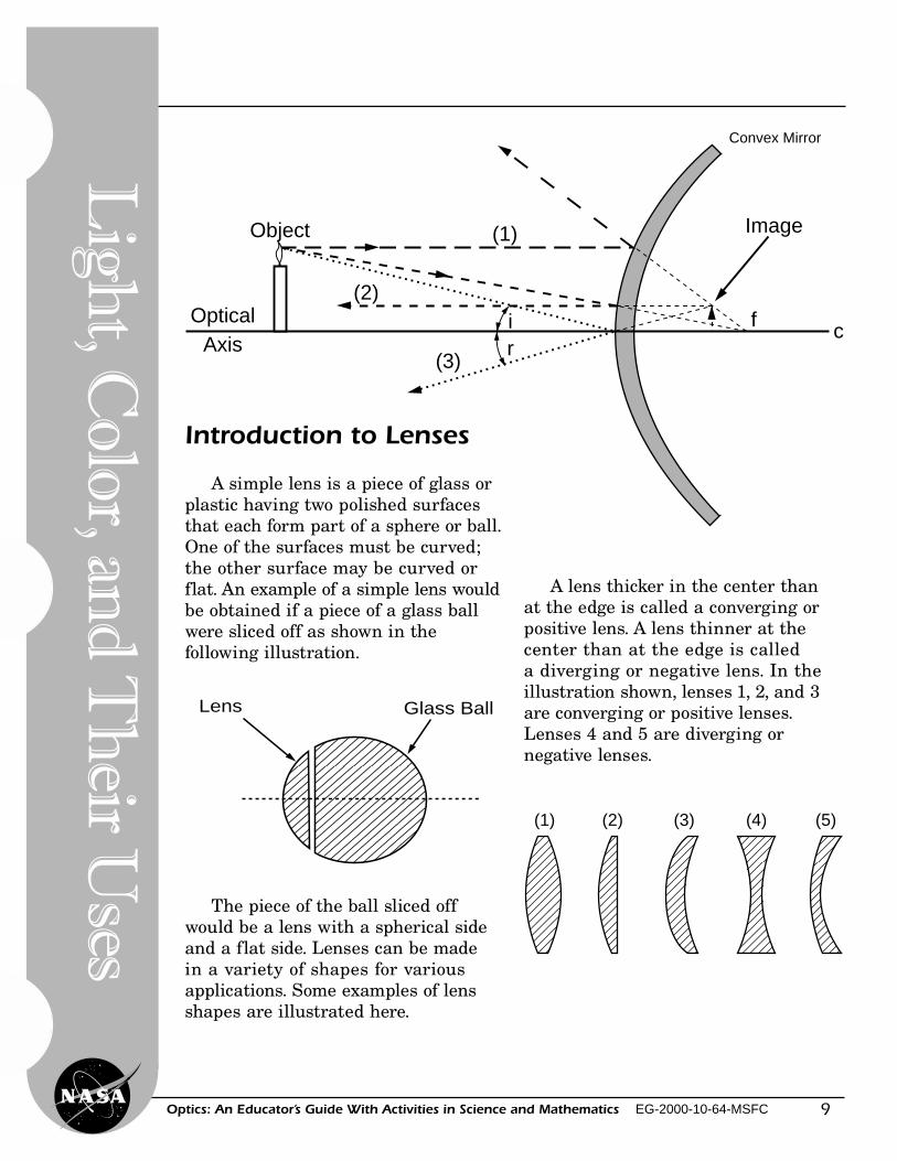
The Image Formed by aConvex Mirror
The image formed by a convexmirror is virtual, upright, and smallerthan the object. This is illustrated bythe ray diagram on the following page.The diagram depicts the three raysthat are discussed in the followingparagraph.
A ray (1) parallel to the optical axisis reflected as if it came from the focalpoint (f). A ray (2) directed toward thefocal point is reflected parallel to theoptical axis. A ray (3) striking themirror at the optical axis is reflectedat an angle equal to the angle ofincidence.
c f
(1)
(3)
(2)
Object
Image
OpticalAxis
Concave Mirror
9Optics: An Educator’s Guide With Activities in Science and Mathematics EG-2000-10-64-MSFC
Convex Mirror
Object
(3)
(1)
c
(2)f
Image
ir
OpticalAxis
Introduction to Lenses
A simple lens is a piece of glass orplastic having two polished surfacesthat each form part of a sphere or ball.One of the surfaces must be curved;the other surface may be curved orflat. An example of a simple lens wouldbe obtained if a piece of a glass ballwere sliced off as shown in thefollowing illustration.
The piece of the ball sliced offwould be a lens with a spherical sideand a flat side. Lenses can be madein a variety of shapes for variousapplications. Some examples of lensshapes are illustrated here.
Glass BallLens
(1) (2) (3) (4) (5)
A lens thicker in the center thanat the edge is called a converging orpositive lens. A lens thinner at thecenter than at the edge is calleda diverging or negative lens. In theillustration shown, lenses 1, 2, and 3are converging or positive lenses.Lenses 4 and 5 are diverging ornegative lenses.
Lig
ht, C
olor, and
Th
eir Uses
10
Lig
ht,
Col
or, a
nd
Th
eir
Use
s
Optics: An Educator’s Guide With Activities in Science and Mathematics EG-2000-10-64-MSFC
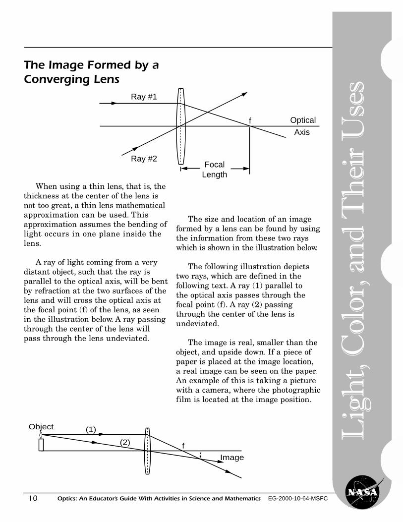
The Image Formed by aConverging Lens
When using a thin lens, that is, thethickness at the center of the lens isnot too great, a thin lens mathematicalapproximation can be used. Thisapproximation assumes the bending oflight occurs in one plane inside thelens.
A ray of light coming from a verydistant object, such that the ray isparallel to the optical axis, will be bentby refraction at the two surfaces of thelens and will cross the optical axis atthe focal point (f) of the lens, as seenin the illustration below. A ray passingthrough the center of the lens willpass through the lens undeviated.
Object
Image
f
(1)
(2)
The size and location of an imageformed by a lens can be found by usingthe information from these two rayswhich is shown in the illustration below.
The following illustration depictstwo rays, which are defined in thefollowing text. A ray (1) parallel tothe optical axis passes through thefocal point (f). A ray (2) passingthrough the center of the lens isundeviated.
The image is real, smaller than theobject, and upside down. If a piece ofpaper is placed at the image location,a real image can be seen on the paper.An example of this is taking a picturewith a camera, where the photographicfilm is located at the image position.
Optical
Axis
FocalLength
f
Ray #1
Ray #2
11Optics: An Educator’s Guide With Activities in Science and Mathematics EG-2000-10-64-MSFC
A Simple Magnifier
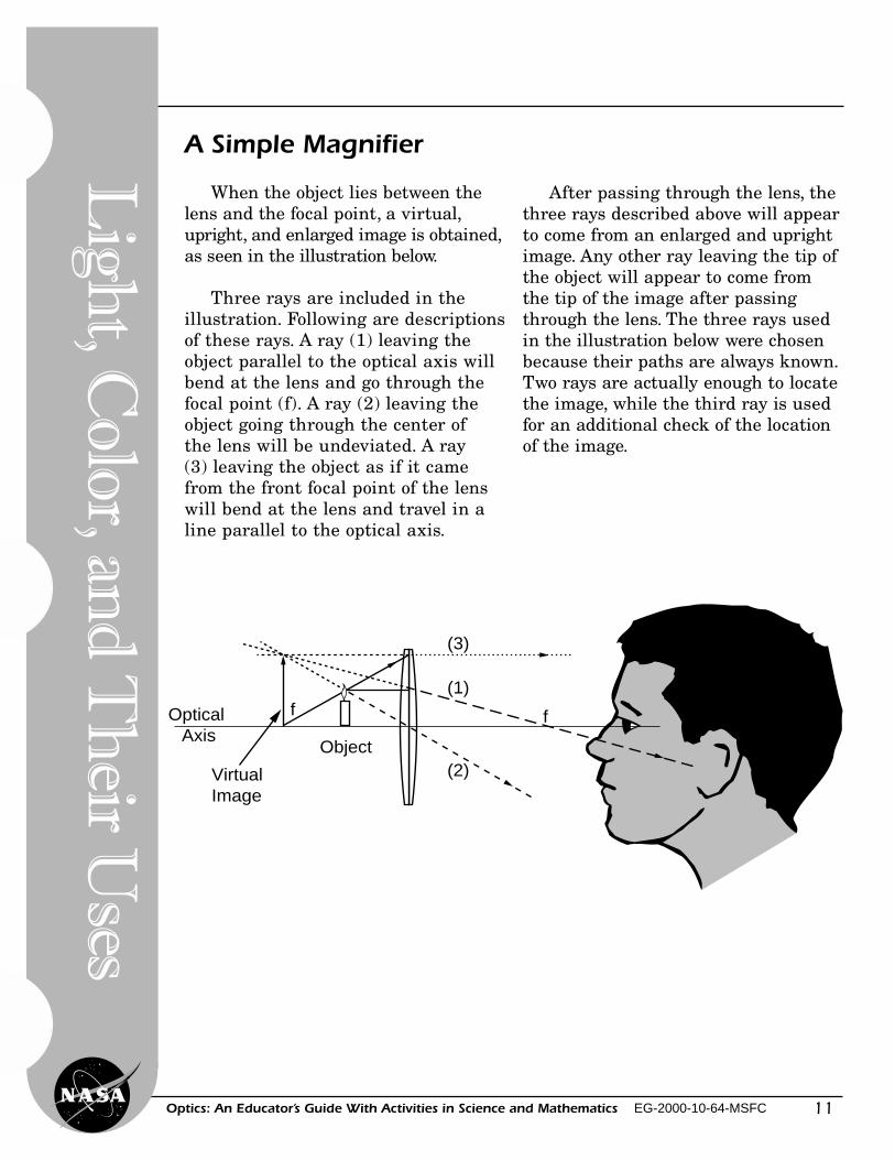
When the object lies between thelens and the focal point, a virtual,upright, and enlarged image is obtained,as seen in the illustration below.
Three rays are included in theillustration. Following are descriptionsof these rays. A ray (1) leaving theobject parallel to the optical axis willbend at the lens and go through thefocal point (f). A ray (2) leaving theobject going through the center ofthe lens will be undeviated. A ray(3) leaving the object as if it camefrom the front focal point of the lenswill bend at the lens and travel in aline parallel to the optical axis.
Object
VirtualImage
Optical Axis
f
(3)
(1)
(2)
f
After passing through the lens, thethree rays described above will appearto come from an enlarged and uprightimage. Any other ray leaving the tip ofthe object will appear to come fromthe tip of the image after passingthrough the lens. The three rays usedin the illustration below were chosenbecause their paths are always known.Two rays are actually enough to locatethe image, while the third ray is usedfor an additional check of the locationof the image.
Lig
ht, C
olor, and
Th
eir Uses
12
Lig
ht,
Col
or, a
nd
Th
eir
Use
s
Optics: An Educator’s Guide With Activities in Science and Mathematics EG-2000-10-64-MSFC
13Optics: An Educator’s Guide With Activities in Science and Mathematics EG-2000-10-64-MSFC
Reflectio
n
Level: Grades (K-4), (5-8)Activity: 1
Reflection of Light With aPlane (Flat) Mirror—Trace a Star
A
B
Objective
The student will experiment withreflection by using a plane mirror.
Science Standards� Science as Inquiry� Physical Science
Mathematics Standards� Problem Solving� Communication� Connection� Computation/Estimation� Measurement
Science and Mathematics Standards
Materials
Theory
Flat mirrors are also called planemirrors. Light rays that fall upon asurface are called incident rays. Theangle at which light strikes a planemirror from an object is called theangle of incidence. The angle at whichlight is reflected from the mirror iscalled the angle of reflection.
• 2 blocks of wood 8 inches long• 1 piece of cardboard 8 inches × 5
inches• 1 mirror tile (1 foot square backed
with heavy cardboard sealed on theedges with thick tape)
• thick tape (duct tape)• heavy cardboard• tracing patterns (on page 15)• pencil• paper, white
14
Lig
ht,
Col
or, a
nd
Th
eir
Use
s
Optics: An Educator’s Guide With Activities in Science and Mathematics EG-2000-10-64-MSFC
A B
C D
Procedures
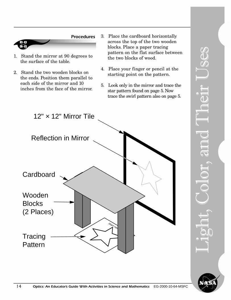
1. Stand the mirror at 90 degrees tothe surface of the table.
2. Stand the two wooden blocks onthe ends. Position them parallel toeach side of the mirror and 10inches from the face of the mirror.
Start Here
Reflection in Mirror
12" × 12" Mirror Tile
Cardboard
Wooden Blocks (2 Places)
Tracing Pattern
3. Place the cardboard horizontallyacross the top of the two woodenblocks. Place a paper tracingpattern on the flat surface betweenthe two blocks of wood.
4. Place your finger or pencil at thestarting point on the pattern.
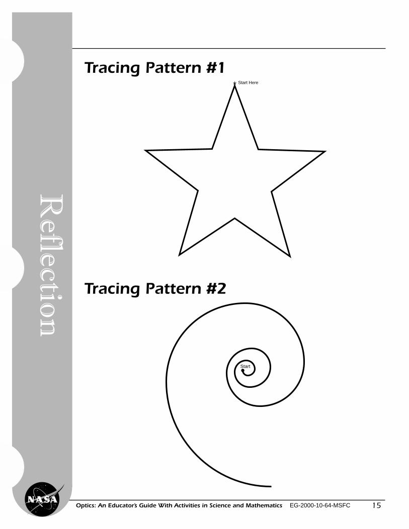
5. Look only in the mirror and trace thestar pattern found on page 5. Nowtrace the swirl pattern also on page 5.
15Optics: An Educator’s Guide With Activities in Science and Mathematics EG-2000-10-64-MSFC
Tracing Pattern #1Start Here*
Reflectio
n
Tracing Pattern #2
Start
16
Lig
ht,
Col
or, a
nd
Th
eir
Use
s
Optics: An Educator’s Guide With Activities in Science and Mathematics EG-2000-10-64-MSFC
Observations, Data, and Conclusions
1. What did you learn after tracingthe two patterns?
2. What information did your eyesgive you?
3. What information did your brain orbody give you?
4. Where did the hand in the mirrorseem to be located when you lookedin the mirror?
5. Is it harder to trace a pattern withyour finger or with a pencil? Why?
6. What characteristic of light did youlearn about when you did this activity?
7. After completing these questions, drawsome designs of your own. Exchangeyour designs with another studentand trace their designs.
Design Page
17Optics: An Educator’s Guide With Activities in Science and Mathematics EG-2000-10-64-MSFC
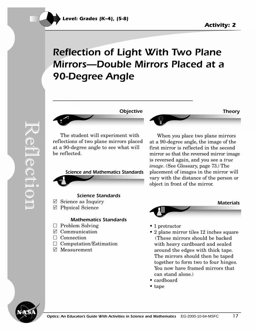
Reflection of Light With Two PlaneMirrors—Double Mirrors Placed at a90-Degree Angle
A
B
Objective
Science and Mathematics Standards
Materials
Theory
When you place two plane mirrorsat a 90-degree angle, the image of thefirst mirror is reflected in the secondmirror so that the reversed mirror imageis reversed again, and you see a trueimage. (See Glossary, page 73.) Theplacement of images in the mirror willvary with the distance of the person orobject in front of the mirror.
• 1 protractor• 2 plane mirror tiles 12 inches square
(These mirrors should be backedwith heavy cardboard and sealedaround the edges with thick tape.The mirrors should then be tapedtogether to form two to four hinges.You now have framed mirrors thatcan stand alone.)
• cardboard• tape
Level: Grades (K–4), (5-8)Activity: 2
The student will experiment withreflections of two plane mirrors placedat a 90-degree angle to see what willbe reflected.
Science Standards� Science as Inquiry� Physical Science
Mathematics Standards� Problem Solving� Communication� Connection� Computation/Estimation� Measurement
Reflectio
n
18
Lig
ht,
Col
or, a
nd
Th
eir
Use
s
Optics: An Educator’s Guide With Activities in Science and Mathematics EG-2000-10-64-MSFC
A B
C D
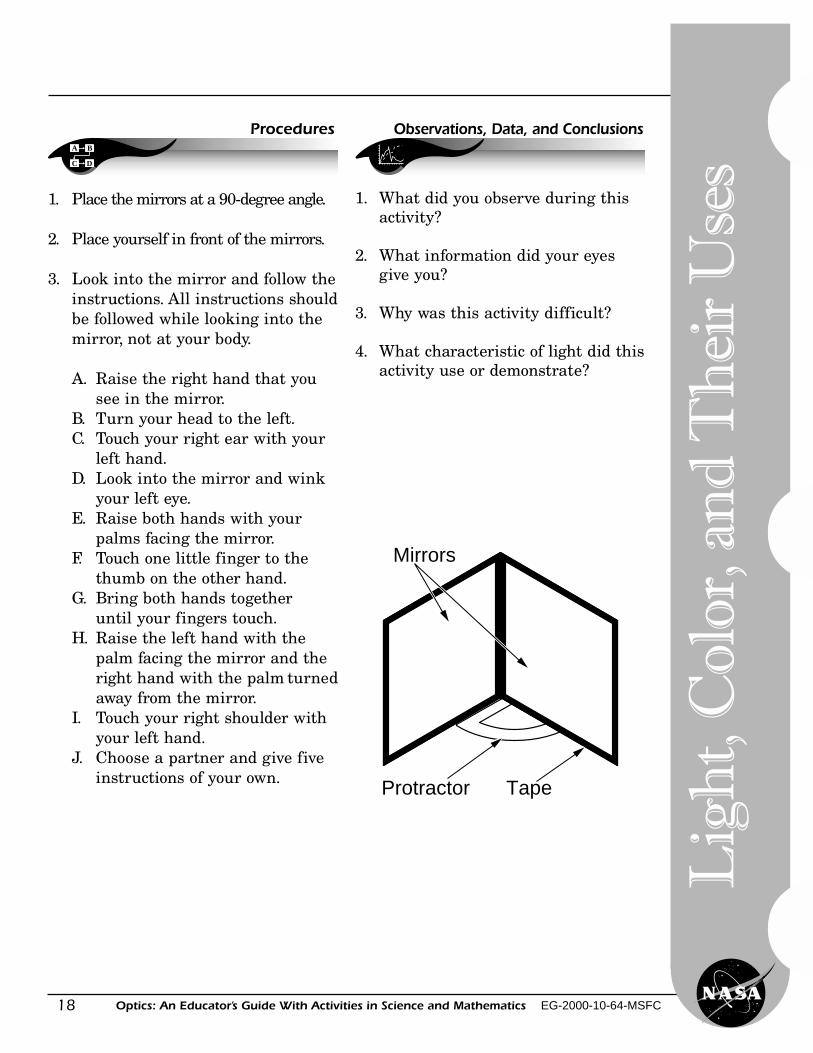
Procedures
Protractor Tape
Mirrors
1. Place the mirrors at a 90-degree angle.
2. Place yourself in front of the mirrors.
3. Look into the mirror and follow theinstructions. All instructions shouldbe followed while looking into themirror, not at your body.
A. Raise the right hand that yousee in the mirror.
B. Turn your head to the left.C. Touch your right ear with your
left hand.D. Look into the mirror and wink
your left eye.E. Raise both hands with your
palms facing the mirror.F. Touch one little finger to the
thumb on the other hand.G. Bring both hands together
until your fingers touch.H. Raise the left hand with the
palm facing the mirror and theright hand with the palm turnedaway from the mirror.
I. Touch your right shoulder withyour left hand.
J. Choose a partner and give fiveinstructions of your own.
Observations, Data, and Conclusions
1. What did you observe during thisactivity?
2. What information did your eyesgive you?
3. Why was this activity difficult?
4. What characteristic of light did thisactivity use or demonstrate?
19Optics: An Educator’s Guide With Activities in Science and Mathematics EG-2000-10-64-MSFC
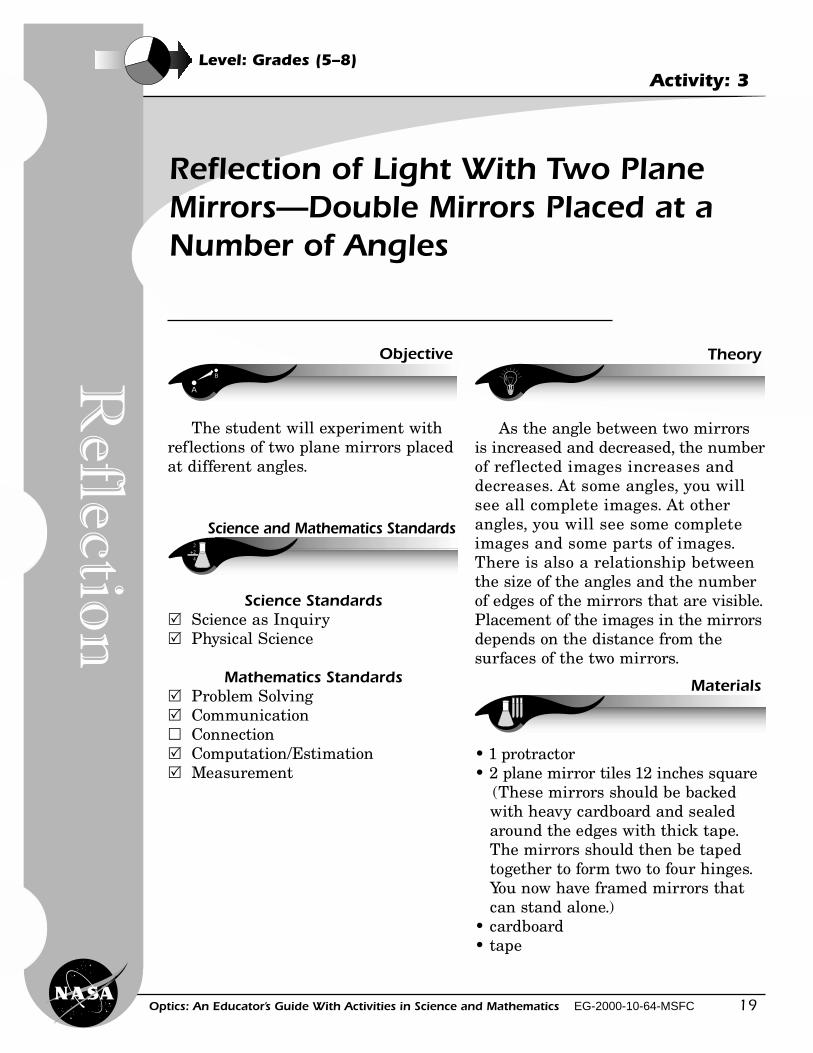
Reflection of Light With Two PlaneMirrors—Double Mirrors Placed at aNumber of Angles
Level: Grades (5–8)Activity: 3
Reflectio
n
A
B
Objective
Science and Mathematics Standards
Materials
Theory
The student will experiment withreflections of two plane mirrors placedat different angles.
Science Standards� Science as Inquiry� Physical Science
Mathematics Standards� Problem Solving� Communication� Connection� Computation/Estimation� Measurement
As the angle between two mirrorsis increased and decreased, the numberof reflected images increases anddecreases. At some angles, you willsee all complete images. At otherangles, you will see some completeimages and some parts of images.There is also a relationship betweenthe size of the angles and the numberof edges of the mirrors that are visible.Placement of the images in the mirrorsdepends on the distance from thesurfaces of the two mirrors.
• 1 protractor• 2 plane mirror tiles 12 inches square
(These mirrors should be backedwith heavy cardboard and sealedaround the edges with thick tape.The mirrors should then be tapedtogether to form two to four hinges.You now have framed mirrors thatcan stand alone.)
• cardboard• tape
20
Lig
ht,
Col
or, a
nd
Th
eir
Use
s
Optics: An Educator’s Guide With Activities in Science and Mathematics EG-2000-10-64-MSFC
A B
C D
Procedures
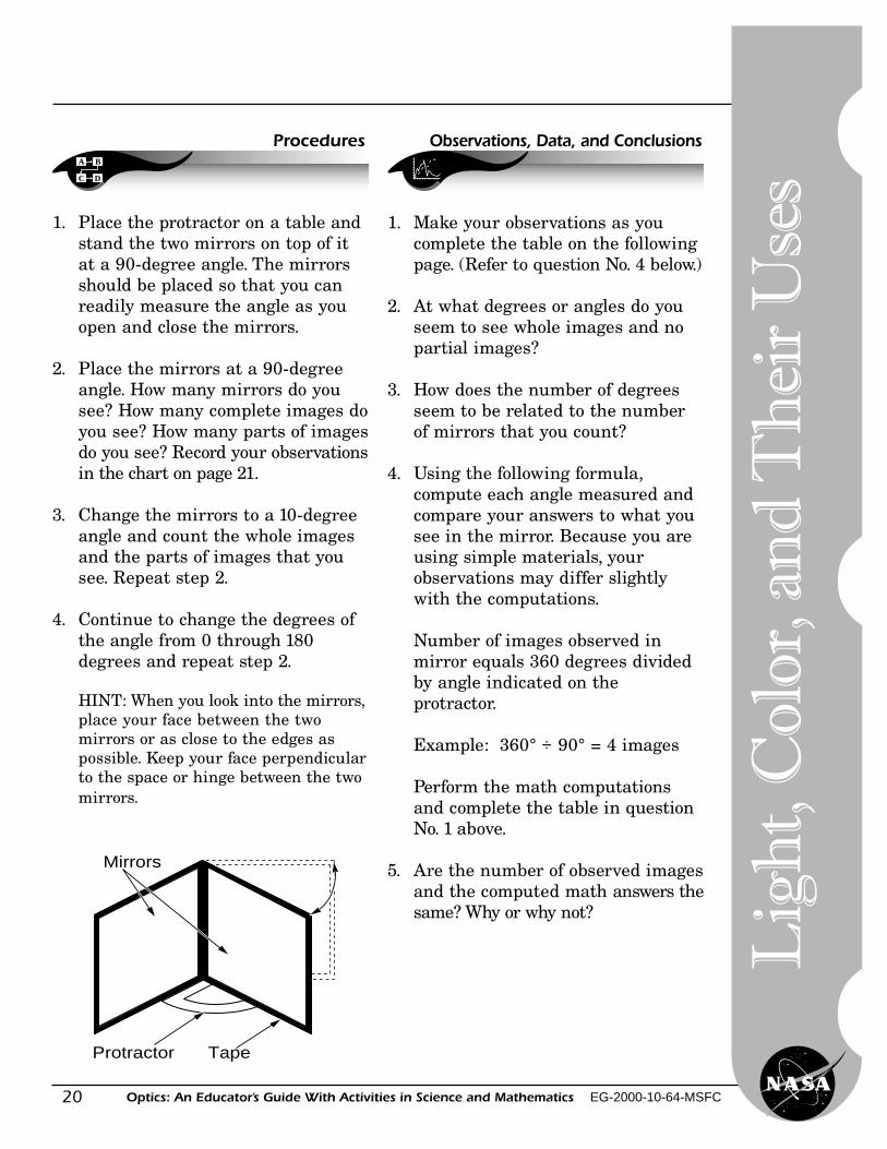
1. Place the protractor on a table andstand the two mirrors on top of itat a 90-degree angle. The mirrorsshould be placed so that you canreadily measure the angle as youopen and close the mirrors.
2. Place the mirrors at a 90-degreeangle. How many mirrors do yousee? How many complete images doyou see? How many parts of imagesdo you see? Record your observationsin the chart on page 21.
3. Change the mirrors to a 10-degreeangle and count the whole imagesand the parts of images that yousee. Repeat step 2.
4. Continue to change the degrees ofthe angle from 0 through 180degrees and repeat step 2.
HINT: When you look into the mirrors,place your face between the twomirrors or as close to the edges aspossible. Keep your face perpendicularto the space or hinge between the twomirrors.
Protractor Tape
Mirrors
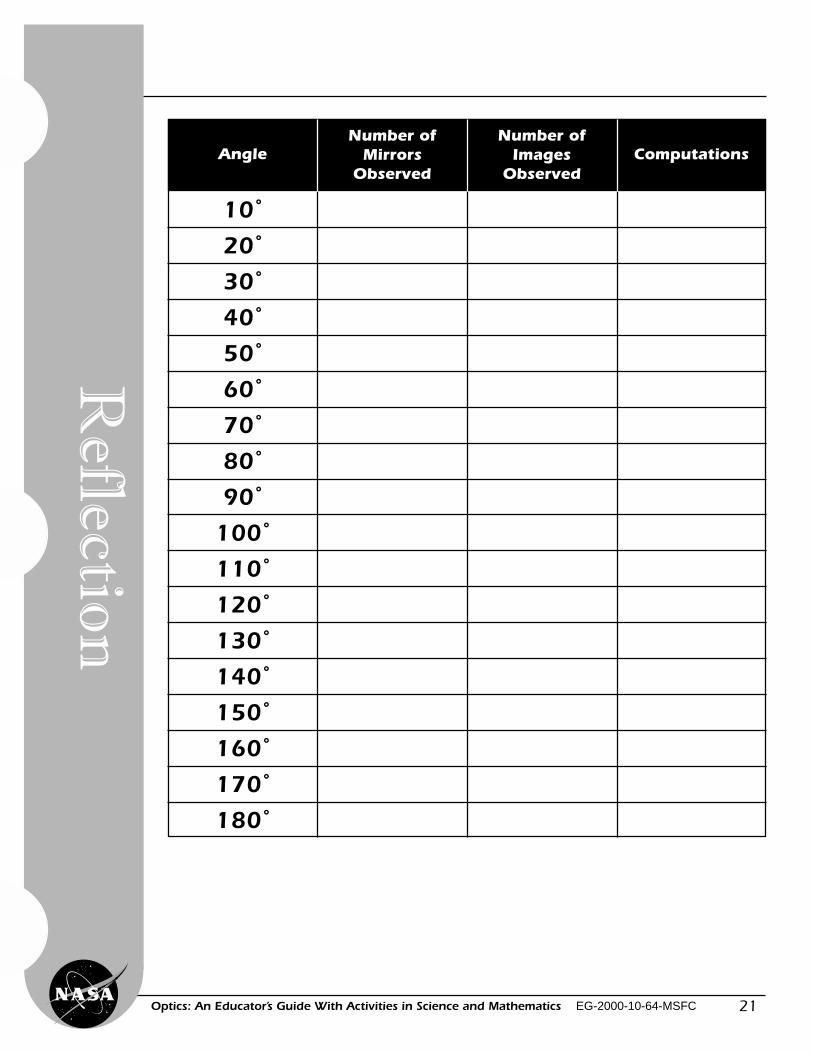
1. Make your observations as youcomplete the table on the followingpage. (Refer to question No. 4 below.)
2. At what degrees or angles do youseem to see whole images and nopartial images?
3. How does the number of degreesseem to be related to the numberof mirrors that you count?
4. Using the following formula,compute each angle measured andcompare your answers to what yousee in the mirror. Because you areusing simple materials, yourobservations may differ slightlywith the computations.
Number of images observed inmirror equals 360 degrees dividedby angle indicated on theprotractor.
Example: 360° ÷ 90° = 4 images
Perform the math computationsand complete the table in questionNo. 1 above.
5. Are the number of observed imagesand the computed math answers thesame? Why or why not?
Observations, Data, and Conclusions
21Optics: An Educator’s Guide With Activities in Science and Mathematics EG-2000-10-64-MSFC
AngleNumber of
MirrorsObserved
Number ofImages
ObservedComputations
10˚
20˚
30˚
40˚
50˚
60˚
70˚
80˚
90˚
100˚
110˚
120˚
130˚
140˚
150˚
160˚
170˚
180˚
Reflectio
n
22
Lig
ht,
Col
or, a
nd
Th
eir
Use
s
Optics: An Educator’s Guide With Activities in Science and Mathematics EG-2000-10-64-MSFC
Math Computations:
23Optics: An Educator’s Guide With Activities in Science and Mathematics EG-2000-10-64-MSFC
Making a Kaleidoscope
Level: Grades (9–12)Activity: 4
A
B
Objective
Science and Mathematics Standards
Theory
Materials
The student will experiment withmultiple reflections in mirrors.
Science Standards� Science as Inquiry� Physical Science
Mathematics Standards� Problem Solving� Communication� Connection� Computation/Estimation� Measurement
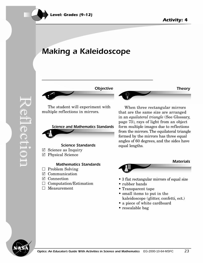
When three rectangular mirrorsthat are the same size are arrangedin an equilateral triangle (See Glossary,page 73), rays of light from an objectform multiple images due to reflectionsfrom the mirrors. The equilateral triangleformed by the mirrors has three equalangles of 60 degrees, and the sides haveequal lengths.
• 3 flat rectangular mirrors of equal size• rubber bands• Transparent tape• small items to put in the
kaleidoscope (glitter, confetti, ect.)• a piece of white cardboard• resealable bag
Reflectio
n
24
Lig
ht,
Col
or, a
nd
Th
eir
Use
s
Optics: An Educator’s Guide With Activities in Science and Mathematics EG-2000-10-64-MSFC
A B
C D
Procedures
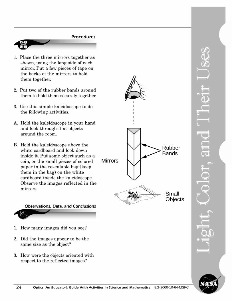
1. Place the three mirrors together asshown, using the long side of eachmirror. Put a few pieces of tape onthe backs of the mirrors to holdthem together.
2. Put two of the rubber bands aroundthem to hold them securely together.
3. Use this simple kaleidoscope to dothe following activities.
A. Hold the kaleidoscope in your handand look through it at objectsaround the room.
B. Hold the kaleidoscope above thewhite cardboard and look downinside it. Put some object such as acoin, or the small pieces of coloredpaper in the resealable bag (keepthem in the bag) on the whitecardboard inside the kaleidoscope.Observe the images reflected in themirrors.
Mirrors
Small Objects
RubberBands
Observations, Data, and Conclusions
1. How many images did you see?
2. Did the images appear to be thesame size as the object?
3. How were the objects oriented withrespect to the reflected images?
25Optics: An Educator’s Guide With Activities in Science and Mathematics EG-2000-10-64-MSFC
Construction of a LargeKaleidoscope Using PVC Pipe(Adult Supervision Is Requiredat All Times)
Junior Home Scientist Project
Materials
• 1 piece of PVC pipe 10 centimeters(about 4 inches) in diameter andabout 16 inches long
• 12-inch mirror tile• hack saw with fine blade• 1 glass cutter• sandpaper• flat black spray paint• white glue• epoxy glue• cardboard• foam rubber used for packing and
shipping• scissors or utility knife• thick leather gloves• red, blue, or yellow paint (optional)• contact paper (optional)
A B
C D
Procedures
1. Buy or cut to size the 16-inchlength of PVC pipe. Sand the edgesand corners of the pipe until theyare smooth.
2. Use the flat black paint and spraythe inside of the pipe. Leave thepaint to dry overnight. Later, paintthe outside of the pipe any color ordesign that you desire. Contactpaper could also be used.
3. While wearing leather gloves, cutthe 12-inch square mirror tile into3-inch strips. Sand the edges of themirrors.
4. Position the three strips of glassclose to one end of the PVC pipe.Place the mirrors to form three60-degree angles.
5. Use the epoxy to glue the mirrorsinside the pipe. Pack foam behindeach mirror to provide stability.
6. Cut a circular piece of cardboard tofit the inside diameter of the pipe.Cut a 1-inch hole in the middle ofthe cardboard.
Reflectio
n
26
Lig
ht,
Col
or, a
nd
Th
eir
Use
s
Optics: An Educator’s Guide With Activities in Science and Mathematics EG-2000-10-64-MSFC
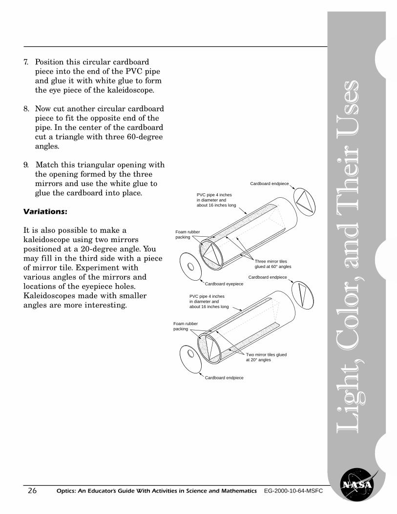
PVC pipe 4 inches in diameter and about 16 inches long
Cardboard endpiece
Foam rubberpacking
Three mirror tilesglued at 60° angles
Cardboard eyepiece
PVC pipe 4 inches in diameter and about 16 inches long
Cardboard endpiece
Foam rubberpacking
Two mirror tiles gluedat 20° angles
Cardboard endpiece
7. Position this circular cardboardpiece into the end of the PVC pipeand glue it with white glue to formthe eye piece of the kaleidoscope.
8. Now cut another circular cardboardpiece to fit the opposite end of thepipe. In the center of the cardboardcut a triangle with three 60-degreeangles.
9. Match this triangular opening withthe opening formed by the threemirrors and use the white glue toglue the cardboard into place.
Variations:
It is also possible to make akaleidoscope using two mirrorspositioned at a 20-degree angle. Youmay fill in the third side with a pieceof mirror tile. Experiment withvarious angles of the mirrors andlocations of the eyepiece holes.Kaleidoscopes made with smallerangles are more interesting.
27Optics: An Educator’s Guide With Activities in Science and Mathematics EG-2000-10-64-MSFC
Making a Periscope
A
B
Objective
Science and Mathematics Standards
Theory
Materials
The student will experiment with asimple periscope to see how it reflects light.
Science Standards� Science as Inquiry� Physical Science
Mathematics Standards� Problem Solving� Communication� Connection� Computation/Estimation� Measurement
A periscope is an optical instrumentthat uses a system of prisms, lenses, ormirrors to reflect images through atube. Light from a distant object strikesthe top mirror and is then reflected atan angle of 90 degrees down theperiscope tube. At the bottom of theperiscope, the light strikes anothermirror and is then reflected into theviewer’s eye. This simple periscope usesonly flat mirrors as compared to theperiscopes used on submarines, whichare usually a complex optical systemusing both lenses and mirrors.
• 2 flat mirrors• a cardboard tube with openings on
each end• wooden supports• tape
Level: Grades (5–8), (9-12)Activity: 5
Reflectio
n
28
Lig
ht,
Col
or, a
nd
Th
eir
Use
s
Optics: An Educator’s Guide With Activities in Science and Mathematics EG-2000-10-64-MSFC
A B
C D
Procedures
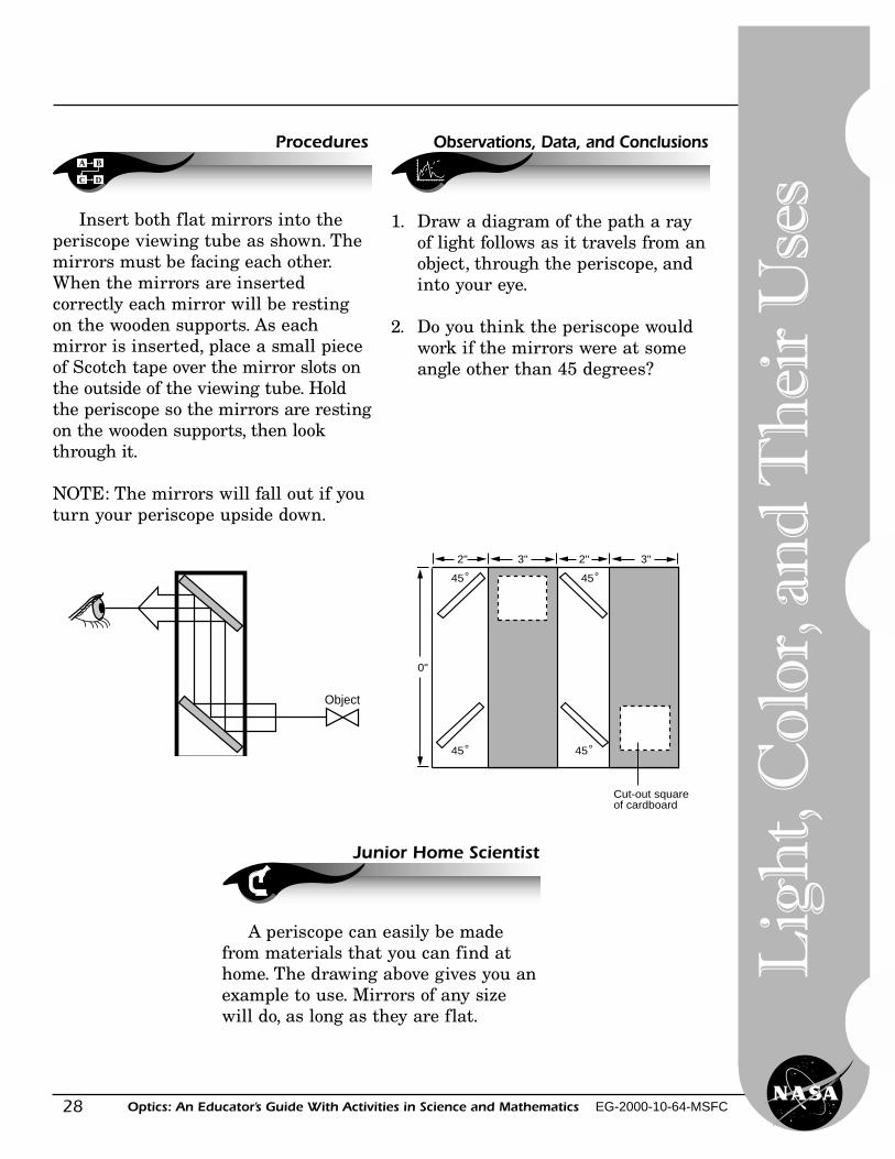
Insert both flat mirrors into theperiscope viewing tube as shown. Themirrors must be facing each other.When the mirrors are insertedcorrectly each mirror will be restingon the wooden supports. As eachmirror is inserted, place a small pieceof Scotch tape over the mirror slots onthe outside of the viewing tube. Holdthe periscope so the mirrors are restingon the wooden supports, then lookthrough it.
NOTE: The mirrors will fall out if youturn your periscope upside down.
Object
0"
2" 3" 2" 3"
45°45°
45° 45°
Cut-out squareof cardboard
Observations, Data, and Conclusions
Junior Home Scientist
1. Draw a diagram of the path a rayof light follows as it travels from anobject, through the periscope, andinto your eye.
2. Do you think the periscope wouldwork if the mirrors were at someangle other than 45 degrees?
A periscope can easily be madefrom materials that you can find athome. The drawing above gives you anexample to use. Mirrors of any sizewill do, as long as they are flat.
29Optics: An Educator’s Guide With Activities in Science and Mathematics EG-2000-10-64-MSFC
Constructing a Spectroscope
Level: Grades (5–8)Activity: 6
A
B
Objective
Science and Mathematics Standards
Theory
Materials
With adult supervision the studentwill construct a simple spectroscope.
Science Standards� Science as Inquiry� Physical Science
Mathematics Standards� Problem Solving� Communication� Connection� Computation/Estimation� Measurement
All elements or pure substances, suchas gold, silver, neon, or hydrogen, give offa set of wavelengths of light when theyare heated. Scientists can study the lightgiven off by stars and other objects inspace or heated substances here onEarth and identify the kinds of elementsthat are present. In fact, the elementhelium, which is a very light gas, wasdiscovered by studying the spectral linesof the Sun. Later, helium was found hereon Earth. Scientists who study light usevery complicated spectroscopes toobserve and measure wavelengths givenoff by light sources.
• 1 cardboard box with lid• sharp knife or blade• 1 double-edged razor blade• scissors• black marker• tape• 1 manila file folder• commercially purchased diffraction
grating (plastic material with 13,440grooves per square inch). (See List ofCatalogs, page 83.)
Diffractio
n
30
Lig
ht,
Col
or, a
nd
Th
eir
Use
s
Optics: An Educator’s Guide With Activities in Science and Mathematics EG-2000-10-64-MSFC
A B
C D
Procedures
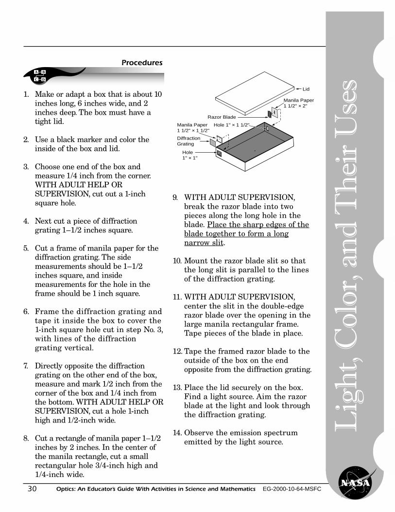
1. Make or adapt a box that is about 10inches long, 6 inches wide, and 2inches deep. The box must have atight lid.
2. Use a black marker and color theinside of the box and lid.
3. Choose one end of the box andmeasure 1/4 inch from the corner.WITH ADULT HELP ORSUPERVISION, cut out a 1-inchsquare hole.
4. Next cut a piece of diffractiongrating 1–1/2 inches square.
5. Cut a frame of manila paper for thediffraction grating. The sidemeasurements should be 1–1/2inches square, and insidemeasurements for the hole in theframe should be 1 inch square.
6. Frame the diffraction grating andtape it inside the box to cover the1-inch square hole cut in step No. 3,with lines of the diffractiongrating vertical.
7. Directly opposite the diffractiongrating on the other end of the box,measure and mark 1/2 inch from thecorner of the box and 1/4 inch fromthe bottom. WITH ADULT HELP ORSUPERVISION, cut a hole 1-inchhigh and 1/2-inch wide.
8. Cut a rectangle of manila paper 1–1/2inches by 2 inches. In the center ofthe manila rectangle, cut a smallrectangular hole 3/4-inch high and1/4-inch wide.
9. WITH ADULT SUPERVISION,break the razor blade into twopieces along the long hole in theblade. Place the sharp edges of theblade together to form a longnarrow slit.
10. Mount the razor blade slit so thatthe long slit is parallel to the linesof the diffraction grating.
11. WITH ADULT SUPERVISION,center the slit in the double-edgerazor blade over the opening in thelarge manila rectangular frame.Tape pieces of the blade in place.
12. Tape the framed razor blade to theoutside of the box on the endopposite from the diffraction grating.
13. Place the lid securely on the box.Find a light source. Aim the razorblade at the light and look throughthe diffraction grating.
14. Observe the emission spectrumemitted by the light source.
Diffraction Grating
Manila Paper1 1/2" × 1 1/2"
Hole1" × 1"
Lid
Razor Blade
Manila Paper1 1/2" × 2"
Hole 1" × 1 1/2"
31Optics: An Educator’s Guide With Activities in Science and Mathematics EG-2000-10-64-MSFC
Exploring DiffractionWith a Spectroscope
Level: Grades (K–4), (5-8)Activity: 7
A
B
Objective
Science and Mathematics Standards
Theory
Materials
The student will be able to seewhat happens to light when it passesthrough a spectroscope.
Science Standards� Science as Inquiry� Physical Science
Mathematics Standards� Problem Solving� Communication� Connection� Computation/Estimation� Measurement
• spectroscope (one spectroscope forfour students)
• light sources (sunlight,incandescent, fluorescent, cadmium,sodium, neon, mercury, helium, etc.)(See List of Catalogs, page 83.)
• diffraction grating• compact disc
A spectroscope is a device that can beused to look at the group of wavelengthsof light given off by an element. Allelements give off a limited number ofwavelengths when they are heated andchanged into gas. Each element always
gives off the same group of wavelengths.This group is called the emissionspectrum of the element.
In the visible wavelengths of theelectromagnetic spectrum, red, with thelongest wavelength, is diffracted most; andviolet, with the shortest wavelength, isdiffracted least. Because each color isdiffracted a different amount, each colorbends at a different angle. The result isa separation of white light into the sevenmajor colors of the spectrum or rainbow.A good way to remember these colors inorder is the name Roy G. Biv. Each letterbegins the name of a color: red, orange,yellow, green, blue, indigo, and violet.(Reference Electromagnetic Spectrumpage 34.)
Diffractio
n
32
Lig
ht,
Col
or, a
nd
Th
eir
Use
s
Optics: An Educator’s Guide With Activities in Science and Mathematics EG-2000-10-64-MSFC
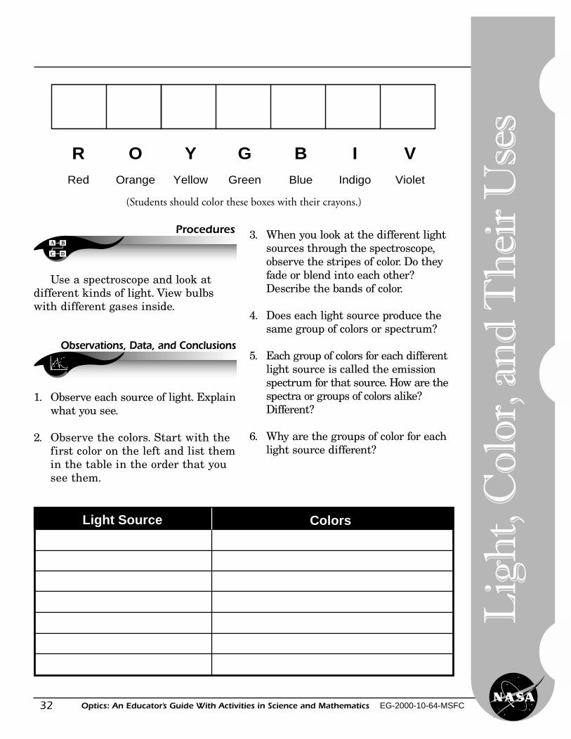
(Students should color these boxes with their crayons.)
R O G B I VRed Orange Green Blue Indigo Violet
YYellow
A B
C D
Procedures
Use a spectroscope and look atdifferent kinds of light. View bulbswith different gases inside.
Observations, Data, and Conclusions
1. Observe each source of light. Explainwhat you see.
2. Observe the colors. Start with thefirst color on the left and list themin the table in the order that yousee them.
3. When you look at the different lightsources through the spectroscope,observe the stripes of color. Do theyfade or blend into each other?Describe the bands of color.
4. Does each light source produce thesame group of colors or spectrum?
5. Each group of colors for each differentlight source is called the emissionspectrum for that source. How are thespectra or groups of colors alike?Different?
6. Why are the groups of color for eachlight source different?
ColorsLight Source
33Optics: An Educator’s Guide With Activities in Science and Mathematics EG-2000-10-64-MSFC
Activities∑∑∑∑
Additional Activities
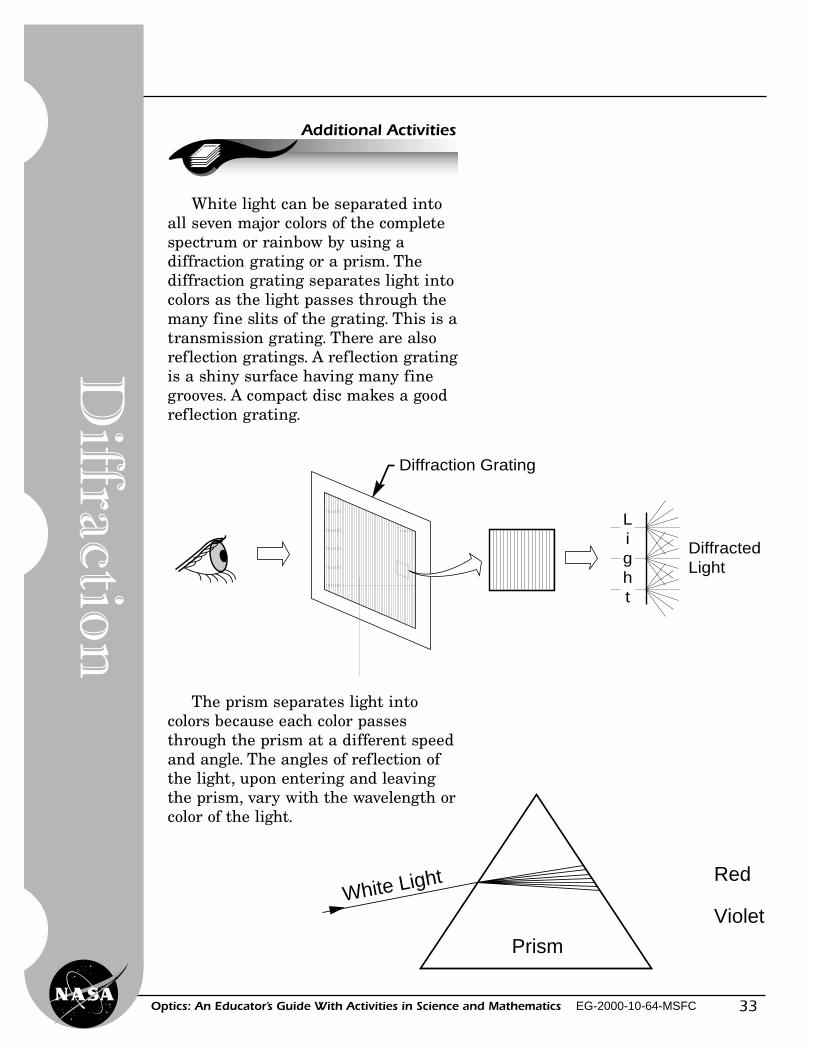
White light can be separated intoall seven major colors of the completespectrum or rainbow by using adiffraction grating or a prism. Thediffraction grating separates light intocolors as the light passes through themany fine slits of the grating. This is atransmission grating. There are alsoreflection gratings. A reflection gratingis a shiny surface having many finegrooves. A compact disc makes a goodreflection grating.
The prism separates light intocolors because each color passesthrough the prism at a different speedand angle. The angles of reflection ofthe light, upon entering and leavingthe prism, vary with the wavelength orcolor of the light.
Light
Diffracted Light
Diffraction Grating
Red
VioletWhite Light
Prism
Diffractio
n
34
Lig
ht,
Col
or, a
nd
Th
eir
Use
s
Optics: An Educator’s Guide With Activities in Science and Mathematics EG-2000-10-64-MSFC
The ElectromagneticSpectrum
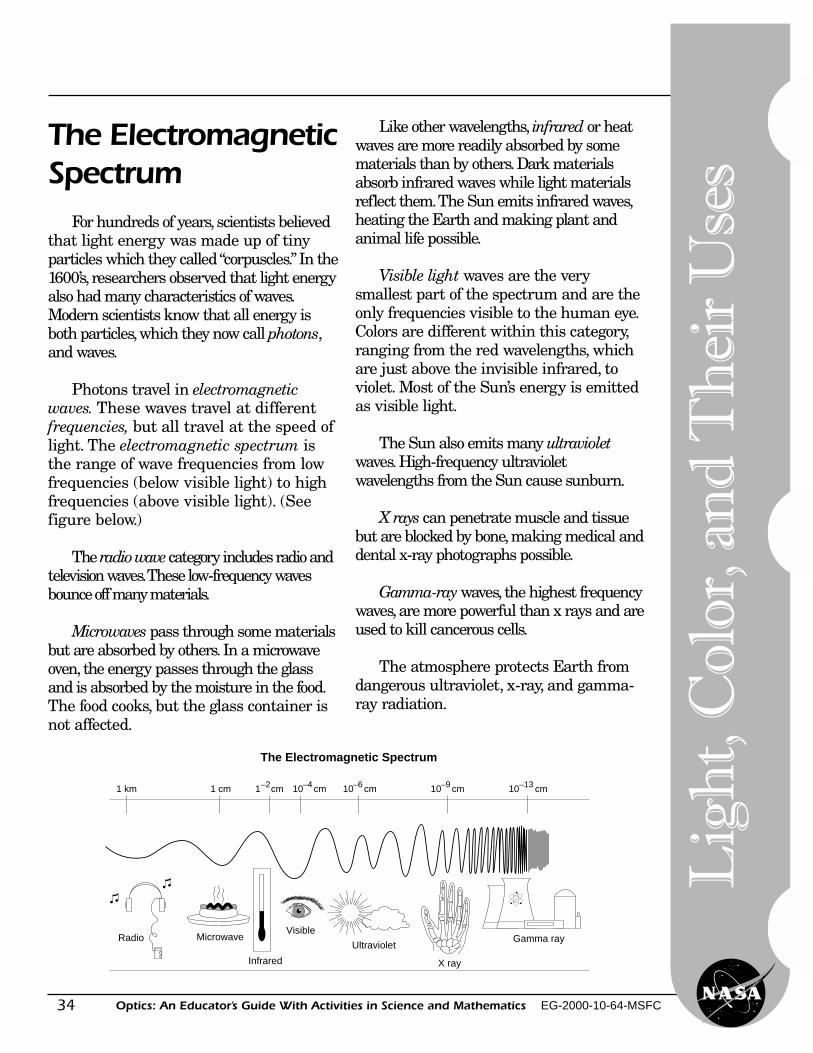
For hundreds of years, scientists believedthat light energy was made up of tinyparticles which they called “corpuscles.” In the1600’s, researchers observed that light energyalso had many characteristics of waves.Modern scientists know that all energy isboth particles, which they now call photons,and waves.
Photons travel in electromagneticwaves. These waves travel at differentfrequencies, but all travel at the speed oflight. The electromagnetic spectrum isthe range of wave frequencies from lowfrequencies (below visible light) to highfrequencies (above visible light). (Seefigure below.)
The radio wave category includes radio andtelevision waves. These low-frequency wavesbounce off many materials.
Microwaves pass through some materialsbut are absorbed by others. In a microwaveoven, the energy passes through the glassand is absorbed by the moisture in the food.The food cooks, but the glass container isnot affected.
Like other wavelengths, infrared or heatwaves are more readily absorbed by somematerials than by others. Dark materialsabsorb infrared waves while light materialsreflect them. The Sun emits infrared waves,heating the Earth and making plant andanimal life possible.
Visible light waves are the verysmallest part of the spectrum and are theonly frequencies visible to the human eye.Colors are different within this category,ranging from the red wavelengths, whichare just above the invisible infrared, toviolet. Most of the Sun’s energy is emittedas visible light.
The Sun also emits many ultravioletwaves. High-frequency ultravioletwavelengths from the Sun cause sunburn.
X rays can penetrate muscle and tissuebut are blocked by bone, making medical anddental x-ray photographs possible.
Gamma-ray waves, the highest frequencywaves, are more powerful than x rays and areused to kill cancerous cells.
The atmosphere protects Earth fromdangerous ultraviolet, x-ray, and gamma-ray radiation.
1 km 1 cm 1 cm–2 10 cm–4 10 cm–6 10 cm–9 10 cm–13
Gamma ray
X ray
Ultraviolet
Visible
Infrared
MicrowaveRadio
The Electromagnetic Spectrum
35Optics: An Educator’s Guide With Activities in Science and Mathematics EG-2000-10-64-MSFC
Diffraction of Light byVery Small Apertures
Level: Grades (9–12)Activity: 8
A
B
Objective
Science and Mathematics Standards
Theory
Materials
The student will observe that whenlight passes through a small hole, it nolonger travels in a straight line. Theobserved light pattern illustrates thewave behavior of light. The student willdetermine what light pattern is createdby light passing through eachdiffraction screen.
Science Standards� Science as Inquiry� Physical Science
Mathematics Standards� Problem Solving� Communication� Connection� Computation/Estimation� Measurement
When light passes through a smallhole or a narrow slit, the light wavesspread out. The hole or slit must beextremely small for the effect of thisspreading to be seen. Each point of thehole or slit acts like a source of aspherical wave. At certain angles, thespherical waves from all the pointswill be in phase and will add to forma bright spot. At other angles thewaves will be out of phase and willcancel to form a dark spot. The patternof light and dark is called the diffractionpattern. The diffraction patterndepends on the shape of the aperture(square or slits). (See Glossary, page 73).
• 2 diffraction screens, one of narrowparallel slits and one of squareapertures (See List of Catalogs, page 83.)
• a distant or point light source
Diffractio
n
36
Lig
ht,
Col
or, a
nd
Th
eir
Use
s
Optics: An Educator’s Guide With Activities in Science and Mathematics EG-2000-10-64-MSFC
A B
C D
Procedures
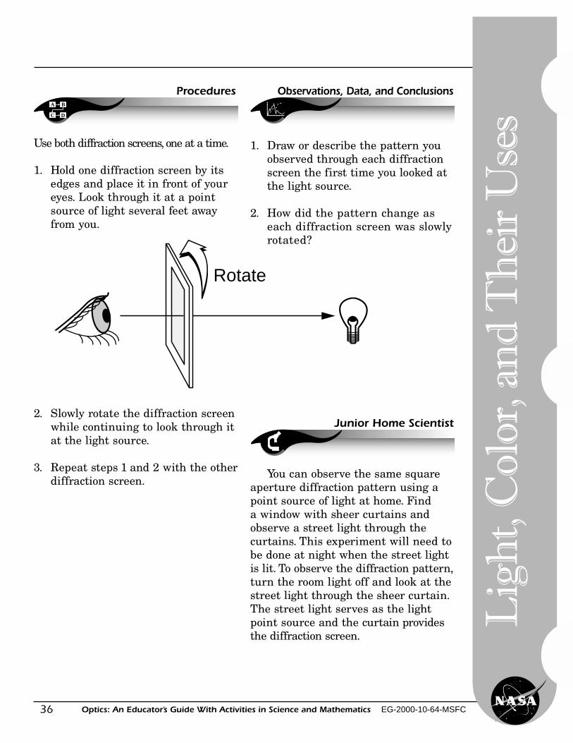
Use both diffraction screens, one at a time.
1. Hold one diffraction screen by itsedges and place it in front of youreyes. Look through it at a pointsource of light several feet awayfrom you.
2. Slowly rotate the diffraction screenwhile continuing to look through itat the light source.
3. Repeat steps 1 and 2 with the otherdiffraction screen.
Rotate
Observations, Data, and Conclusions
1. Draw or describe the pattern youobserved through each diffractionscreen the first time you looked atthe light source.
2. How did the pattern change aseach diffraction screen was slowlyrotated?
Junior Home Scientist
You can observe the same squareaperture diffraction pattern using apoint source of light at home. Finda window with sheer curtains andobserve a street light through thecurtains. This experiment will need tobe done at night when the street lightis lit. To observe the diffraction pattern,turn the room light off and look at thestreet light through the sheer curtain.The street light serves as the lightpoint source and the curtain providesthe diffraction screen.
37Optics: An Educator’s Guide With Activities in Science and Mathematics EG-2000-10-64-MSFC
A
B
Objective
Science and Mathematics Standards
Theory
Materials
Discovering Color With a Prism
Level: Grades (9–12)Activity: 9
The student will observe whathappens to light as it passes througha prism. The student will experimentwith white light that is composed of acontinuous band of colors. The band ofcolors appears in the same pattern asthe colors of a rainbow.
Science Standards� Science as Inquiry� Physical Science
Mathematics Standards� Problem Solving� Communication� Connection� Computation/Estimation� Measurement
This experiment was first done bySir Isaac Newton (1642–1727). Newtonlet a beam of sunlight pass through aglass prism and observed the white lightspectrum. In a vacuum, light of all colorstravels at the same speed. When lightpasses through a material, such as glassor water, the red light at one end of thespectrum travels faster than the violetlight at the other end of the spectrum.This difference in speed causes a changein the direction of light when going fromair to glass and from glass to air. Thischange of direction is called refraction,and is greater for violet light than forred light. The speed of light in the glassdepends on the color; thus we get acontinuous band as in the rainbow.
• glass or plastic prism• light sources, including an
incandescent lamp, fluorescent lamp,cadmium lamp
• a prism made out of acrylic plastic(see page 40) (optional)
Co
lor, R
efraction
38
Lig
ht,
Col
or, a
nd
Th
eir
Use
s
Optics: An Educator’s Guide With Activities in Science and Mathematics EG-2000-10-64-MSFC
A B
C D
Procedures
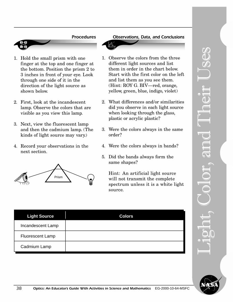
1. Hold the small prism with onefinger at the top and one finger atthe bottom. Position the prism 2 to3 inches in front of your eye. Lookthrough one side of it in thedirection of the light source asshown below.
2. First, look at the incandescentlamp. Observe the colors that arevisible as you view this lamp.
3. Next, view the fluorescent lampand then the cadmium lamp. (Thekinds of light source may vary.)
4. Record your observations in thenext section.
Prism
Incandescent Lamp
Fluorescent Lamp
Cadmium Lamp
Light Source Colors
Observations, Data, and Conclusions
1. Observe the colors from the threedifferent light sources and listthem in order in the chart below.Start with the first color on the leftand list them as you see them.(Hint: ROY G. BIV—red, orange,yellow, green, blue, indigo, violet)
2. What differences and/or similaritiesdid you observe in each light sourcewhen looking through the glass,plastic or acrylic plastic?
3. Were the colors always in the sameorder?
4. Were the colors always in bands?
5. Did the bands always form thesame shapes?
Hint: An artificial light sourcewill not transmit the completespectrum unless it is a white lightsource.
39Optics: An Educator’s Guide With Activities in Science and Mathematics EG-2000-10-64-MSFC
Activities∑∑∑∑
Additional Activities Junior Home Scientist
Repeat the previous activities witha high quality prism (highly dispersive).What differences do you observebetween the acrylic plastic or plasticprism and the prism made out ofoptical quality glass?
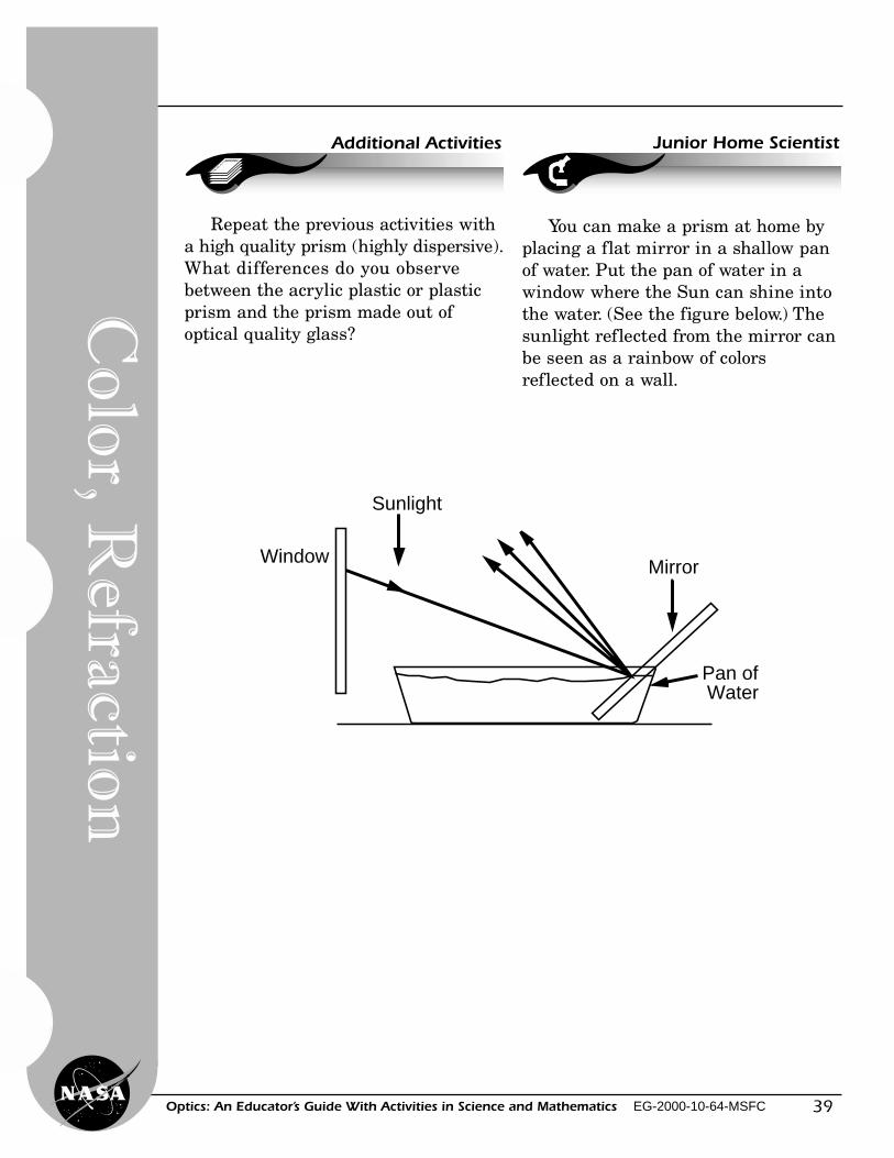
You can make a prism at home byplacing a flat mirror in a shallow panof water. Put the pan of water in awindow where the Sun can shine intothe water. (See the figure below.) Thesunlight reflected from the mirror canbe seen as a rainbow of colorsreflected on a wall.
Sunlight
Window Mirror
Pan of Water
Co
lor, R
efraction
40
Lig
ht,
Col
or, a
nd
Th
eir
Use
s
Optics: An Educator’s Guide With Activities in Science and Mathematics EG-2000-10-64-MSFC
• acrylic plastic about one-half inch thick.
• Hacksaw with fine blade or band saw,very fine sandpaper (400 or 600 grit,possibly available at auto paint stores orauto body repair shops), very fine file,craft felt, silver polish, one small boardwith two tacks (optional).
Junior Home Scientist Project
Materials
A B
C D
Procedures
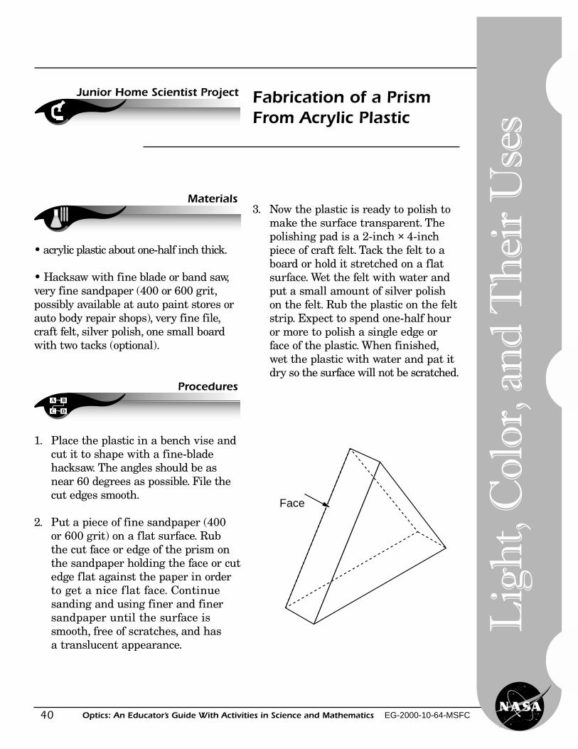
Fabrication of a PrismFrom Acrylic Plastic
Face
1. Place the plastic in a bench vise andcut it to shape with a fine-bladehacksaw. The angles should be asnear 60 degrees as possible. File thecut edges smooth.
2. Put a piece of fine sandpaper (400or 600 grit) on a flat surface. Rubthe cut face or edge of the prism onthe sandpaper holding the face or cutedge flat against the paper in orderto get a nice flat face. Continuesanding and using finer and finersandpaper until the surface issmooth, free of scratches, and hasa translucent appearance.
3. Now the plastic is ready to polish tomake the surface transparent. Thepolishing pad is a 2-inch × 4-inchpiece of craft felt. Tack the felt to aboard or hold it stretched on a flatsurface. Wet the felt with water andput a small amount of silver polishon the felt. Rub the plastic on the feltstrip. Expect to spend one-half houror more to polish a single edge orface of the plastic. When finished,wet the plastic with water and pat itdry so the surface will not be scratched.
Face
41Optics: An Educator’s Guide With Activities in Science and Mathematics EG-2000-10-64-MSFC
Light and Color—Color Spinners
Level: Grades (K–4), (5-8)Activity: 10
A
B
Objective
Science and Mathematics Standards
Theory
Materials
The student will observe the effectsof rapid movement using colors. Thestudent will observe how colors changeand how different colors can be made.
Science Standards� Science as Inquiry� Physical Science
Mathematics Standards� Problem Solving� Communication� Connection� Computation/Estimation� Measurement
Some colors are made by adding orsubtracting parts of the colors in thespectrum. When designs of more thanone color are moved rapidly, thehuman eye sees these colors blendedor mixed.
• strong string such as kite string• white cardboard circles 2 to 4 inches
in diameter• magic markers or washable paint• scissors
Co
lor
42
Lig
ht,
Col
or, a
nd
Th
eir
Use
s
Optics: An Educator’s Guide With Activities in Science and Mathematics EG-2000-10-64-MSFC
A B
C D
Procedures Observations, Data, and Conclusions
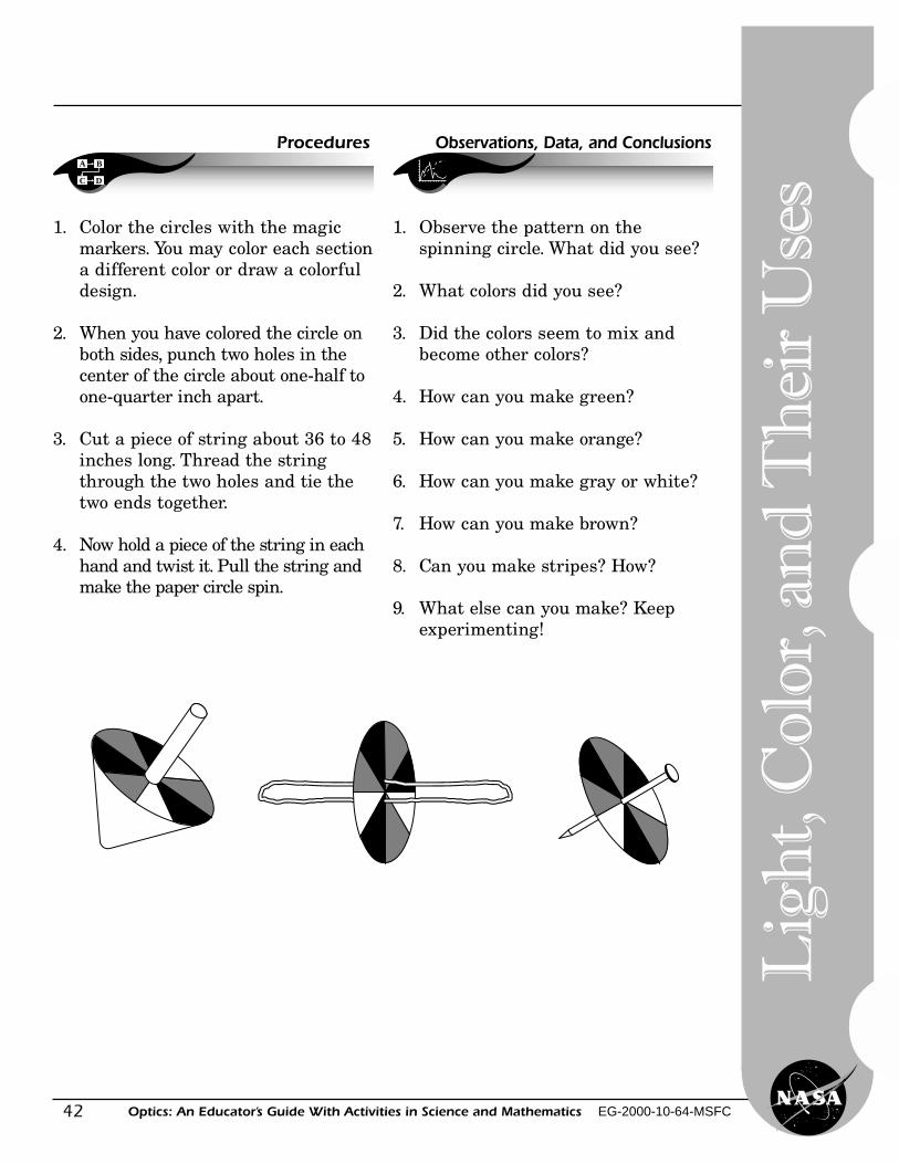
1. Color the circles with the magicmarkers. You may color each sectiona different color or draw a colorfuldesign.
2. When you have colored the circle onboth sides, punch two holes in thecenter of the circle about one-half toone-quarter inch apart.
3. Cut a piece of string about 36 to 48inches long. Thread the stringthrough the two holes and tie thetwo ends together.
4. Now hold a piece of the string in eachhand and twist it. Pull the string andmake the paper circle spin.
1. Observe the pattern on thespinning circle. What did you see?
2. What colors did you see?
3. Did the colors seem to mix andbecome other colors?
4. How can you make green?
5. How can you make orange?
6. How can you make gray or white?
7. How can you make brown?
8. Can you make stripes? How?
9. What else can you make? Keepexperimenting!
43Optics: An Educator’s Guide With Activities in Science and Mathematics EG-2000-10-64-MSFC
Light and Color—Filters
Level: Grades (K–4)Activity: 11
Light is the only source of color.Color pigments (paints, dyes, or inks)show color by absorbing or subtractingcertain parts of the spectrum, andreflecting or transmitting the partsthat remain. The visual sensation ofall the colors can be created by addingdifferent intensities or amounts of thethree primary colors—red, green, andblue. Filters subtract or absorb a bandof wavelengths of color and transmitthe other wavelengths. A yellow filtertransmits yellow and a red filtertransmits red.
• a variety of transparent filters orcellophane of different colors (SeeList of Catalogs, page 83.)
• light source such as a window• slide projector or overhead projector
A
B
Objective
Science and Mathematics Standards
Theory
Materials
The student will experiment withcolor by using a variety of filters.
Science Standards� Science as Inquiry� Physical Science
Mathematics Standards� Problem Solving� Communication� Connection� Computation/Estimation� Measurement
Co
lor
44
Lig
ht,
Col
or, a
nd
Th
eir
Use
s
Optics: An Educator’s Guide With Activities in Science and Mathematics EG-2000-10-64-MSFC
A B
C D
Procedures Observations, Data, and Conclusions
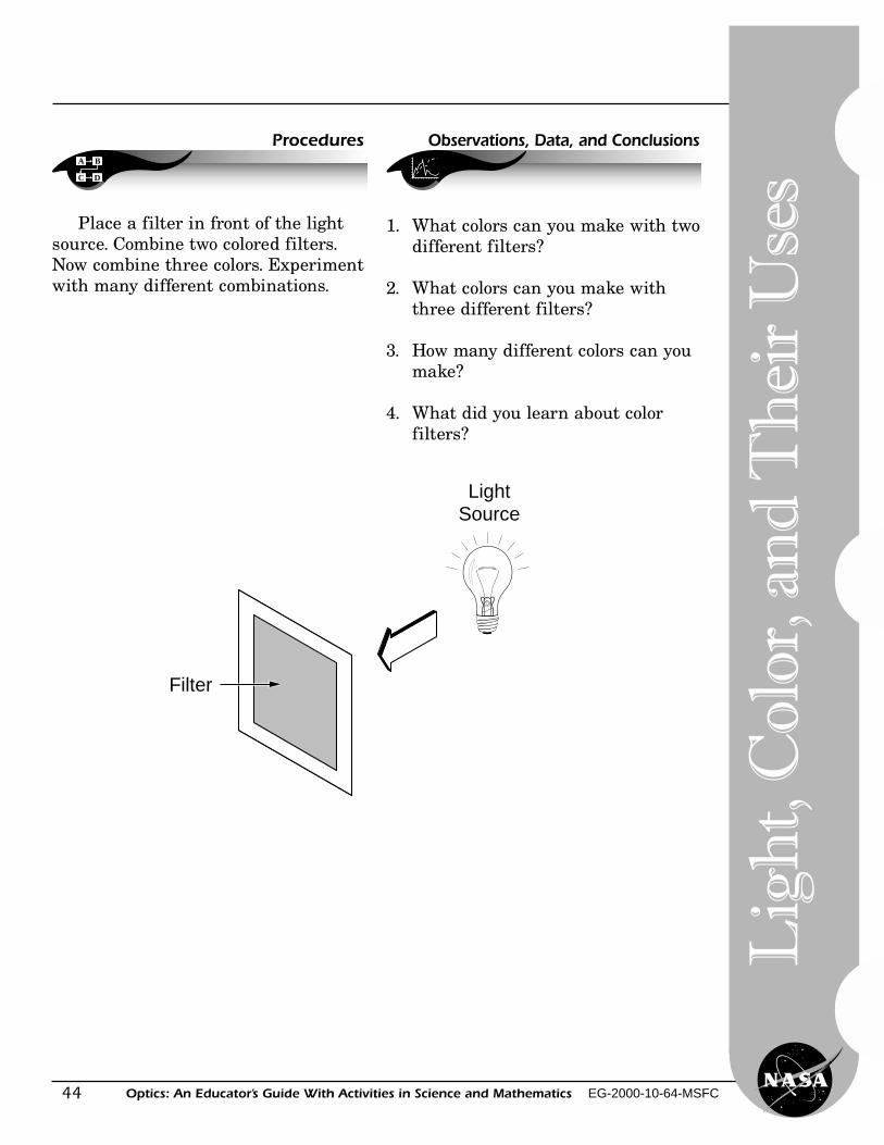
Place a filter in front of the lightsource. Combine two colored filters.Now combine three colors. Experimentwith many different combinations.
1. What colors can you make with twodifferent filters?
2. What colors can you make withthree different filters?
3. How many different colors can youmake?
4. What did you learn about colorfilters?
LightSource
Filter
45Optics: An Educator’s Guide With Activities in Science and Mathematics EG-2000-10-64-MSFC
Light and Color—Hidden Messages
Level: Grades (K–4), (5-8)Activity: 12
A totally transparent piece of glasstransmits all wavelengths of light. Anopaque object will transmit no light atall. A red filter transmits red, a bluefilter transmits blue, and a yellowfilter transmits yellow; so that allother colors are absorbed or subtracted.Some manmade sources of light, suchas fluorescent bulbs, cause objects toappear to be different colors becausethey do not generate all thewavelengths of white light.
• white paper• highlight or pastel magic markers
(three or more colors)• transparent color filter or cellophane
in a variety of colors• a card with several hidden messages
of different colors (handmade)
A
B
Objective
Science and Mathematics Standards
Theory
Materials
The student will construct,experiment, and observe with designsviewed through color filters.
Science Standards� Science as Inquiry� Physical Science
Mathematics Standards� Problem Solving� Communication� Connection� Computation/Estimation� Measurement
Co
lor
46
Lig
ht,
Col
or, a
nd
Th
eir
Use
s
Optics: An Educator’s Guide With Activities in Science and Mathematics EG-2000-10-64-MSFC
1. Using at least 3 different magicmarker colors, draw a design. Thinkin terms of space and astronomydesigns.
2. Use magic markers to draw moredesigns, be sure to include at leastone hidden message in yourdesigns. Can you hide three or moremessages in one design?
(Students should use a space orastronomy word as their hiddenmessage and then draw designsover it.)
3. View the design through severalfilters.
A B
C D
Procedures Observations, Data, and Conclusions
1. When you viewed the designswithout a filter, what did you see?
2. What did you see when you looked atyour design with each colored filter?
3. What did you see when you usedtwo different filters together?
4. Why did you see different thingswith each different filter?
5. If possible, exchange designs withanother person and read theirsecret message.
47Optics: An Educator’s Guide With Activities in Science and Mathematics EG-2000-10-64-MSFC
Simple Magnifiers
Level: Grades (K–4), (5-8)Activity: 13
Simple double-convex lenses can makegood magnifiers. Some transparent bottlesand jars bend light and magnify print.They may also reverse the print. Water ina jar or a drop of water can also serve asa magnifier.
• photographic slide frame or thinpiece of cardboard with a 1-inchsquare hole
• transparent tape• small transparent sauce or
condiment bottles• jars of different shapes• water• old magazine or newspaper
A
B
Objective Science and Mathematics Standards
Science and Mathematics Standards
Materials
The student will experiment withmagnifiers.
Science Standards� Science as Inquiry� Physical Science
Mathematics Standards� Problem Solving� Communication� Connection� Computation/Estimation� Measurement
Len
ses
48
Lig
ht,
Col
or, a
nd
Th
eir
Use
s
Optics: An Educator’s Guide With Activities in Science and Mathematics EG-2000-10-64-MSFC
A B
C D
Procedures Observations, Data, and Conclusions
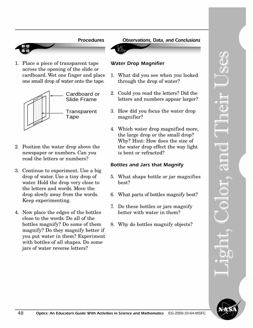
1. Place a piece of transparent tapeacross the opening of the slide orcardboard. Wet one finger and placeone small drop of water onto the tape.
2. Position the water drop above thenewspaper or numbers. Can youread the letters or numbers?
3. Continue to experiment. Use a bigdrop of water. Use a tiny drop ofwater. Hold the drop very close tothe letters and words. Move thedrop slowly away from the words.Keep experimenting.
4. Now place the edges of the bottlesclose to the words. Do all of thebottles magnify? Do some of themmagnify? Do they magnify better ifyou put water in them? Experimentwith bottles of all shapes. Do somejars of water reverse letters?
Water Drop Magnifier
1. What did you see when you lookedthrough the drop of water?
2. Could you read the letters? Did theletters and numbers appear larger?
3. How did you focus the water dropmagnifier?
4. Which water drop magnified more,the large drop or the small drop?Why? Hint: How does the size ofthe water drop effect the way lightis bent or refracted?
Bottles and Jars that Magnify
5. What shape bottle or jar magnifiesbest?
6. What parts of bottles magnify best?
7. Do these bottles or jars magnifybetter with water in them?
8. Why do bottles magnify objects?
Cardboard orSlide Frame
TransparentTape
49Optics: An Educator’s Guide With Activities in Science and Mathematics EG-2000-10-64-MSFC
Level: Grades (9–12)Activity: 14
Focusing Light With a Lens
When light from a source that is aninfinite distance away passes through aconverging lens, the light will come to a
A
B
Objective
Science and Mathematics Standards
Theory
Materials
The student will experiment witha converging lens that has a focal pointwhich can be easily measured. Using alens, the student will observe the imageof an object through a lens and willdetermine the magnification of that lens.
Science Standards� Science as Inquiry� Physical Science
Mathematics Standards� Problem Solving� Communication� Connection� Computation/Estimation� Measurement
focus at the focal point of the lens. Sinceit is inconvenient to get infinite distancesin the classroom, the following lensequation is used to compute the focallength of a lens:
1 1 1— = — + — f Do Di
The measured distance of the object,Do, from the lens, and the measureddistance of the image, Di, are usedto compute the focal length, f, of aconverging lens. A more convenientform of this equation is
Di Dof =
Di + Do
• 2 converging lenses• a white cardboard imaging screen• a meter stick or metric ruler• a 12-inch ruler• a light source (flashlight)• an object such as an arrow made of
tape on the flashlight lens cover
Len
ses, Refractio
n
50
Lig
ht,
Col
or, a
nd
Th
eir
Use
s
Optics: An Educator’s Guide With Activities in Science and Mathematics EG-2000-10-64-MSFC
A B
C D
Procedures
A B
C D
Procedures
Using both lenses, one at a time,complete all the activities in Part 1;then complete Part 2.
Part 1
1. Experiment with the lenses. Holdeach lens above a surface such asyour hand, the writing on this page,the fabric of your clothes, etc. Adjustthe lens until the surface is in focusand you can see the object clearly. Atthis point, we are using the lens asa magnifier. Details of the objectshould be sharp.
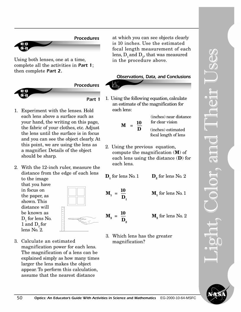
2. With the 12-inch ruler, measure thedistance from the edge of each lensto the imagethat you havein focus onthe paper, asshown. Thisdistance willbe known asD1 for lens No.1 and D2 forlens No. 2.
3. Calculate an estimatedmagnification power for each lens.The magnification of a lens can beexplained simply as how many timeslarger the lens makes the objectappear. To perform this calculation,assume that the nearest distance
12
11
10
9
8
7
6
5
4
3
2
1
at which you can see objects clearlyis 10 inches. Use the estimatedfocal length measurement of eachlens, D1 and D2, that was measuredin the procedure above.
Observations, Data, and Conclusions
1. Using the following equation, calculatean estimate of the magnification foreach lens:
10 M = —
D
(inches) near distancefor clear vision
(inches) estimatedfocal length of lens
2. Using the previous equation,compute the magnification (M) ofeach lens using the distance (D) foreach lens.
D1 for lens No. 1 D2 for lens No. 2
10M1 = — M1 for lens No. 1 D1
10M2 = — M2 for lens No. 2 D2
3. Which lens has the greatermagnification?
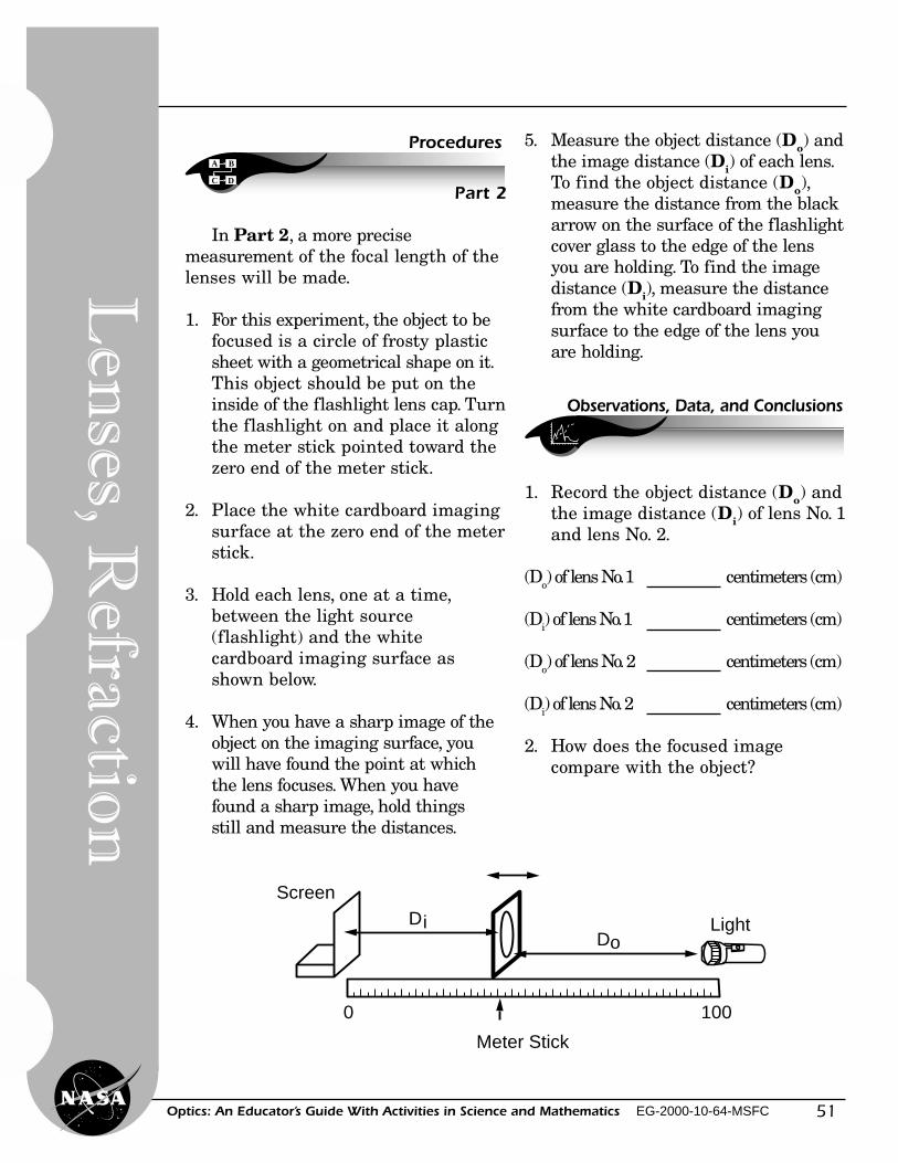
51Optics: An Educator’s Guide With Activities in Science and Mathematics EG-2000-10-64-MSFC
A B
C D
Procedures
Part 2
In Part 2, a more precisemeasurement of the focal length of thelenses will be made.
1. For this experiment, the object to befocused is a circle of frosty plasticsheet with a geometrical shape on it.This object should be put on theinside of the flashlight lens cap. Turnthe flashlight on and place it alongthe meter stick pointed toward thezero end of the meter stick.
2. Place the white cardboard imagingsurface at the zero end of the meterstick.
3. Hold each lens, one at a time,between the light source(flashlight) and the whitecardboard imaging surface asshown below.
4. When you have a sharp image of theobject on the imaging surface, youwill have found the point at whichthe lens focuses. When you havefound a sharp image, hold thingsstill and measure the distances.
Screen
Meter Stick
0 100
DiDo
Light
5. Measure the object distance (Do) andthe image distance (Di) of each lens.To find the object distance (Do),measure the distance from the blackarrow on the surface of the flashlightcover glass to the edge of the lensyou are holding. To find the imagedistance (Di), measure the distancefrom the white cardboard imagingsurface to the edge of the lens youare holding.
Observations, Data, and Conclusions
1. Record the object distance (Do) andthe image distance (Di) of lens No. 1and lens No. 2.
(Do) of lens No. 1 centimeters (cm)
(Di) of lens No. 1 centimeters (cm)
(Do) of lens No. 2 centimeters (cm)
(Di) of lens No. 2 centimeters (cm)
2. How does the focused imagecompare with the object?
Len
ses, Refractio
n
52
Lig
ht,
Col
or, a
nd
Th
eir
Use
s
Optics: An Educator’s Guide With Activities in Science and Mathematics EG-2000-10-64-MSFC
3. If you found two clear images, whatwas different about them? Why werethere two images? (optional)
4. Using the following equation,calculate the focal length of each lensusing the measurements that youhave just made.
The following equation describes how theobject distance, the image distance, and thefocal length are related for a lens.
f = focal length Do = object distance Di = image distance
1 1 1— = — + — f D
o D
i
Which may be written as:
Di Do f = Di
+ Do
Use this equation twice, once for each lens.
Di ××××× Do f1 = Di
+ Do
Focal length lens No. 1 centimeters (cm)
Di ××××× Do f2 = Di
+ Do
Focal length lens No. 2 centimeters (cm)
Math Computation:
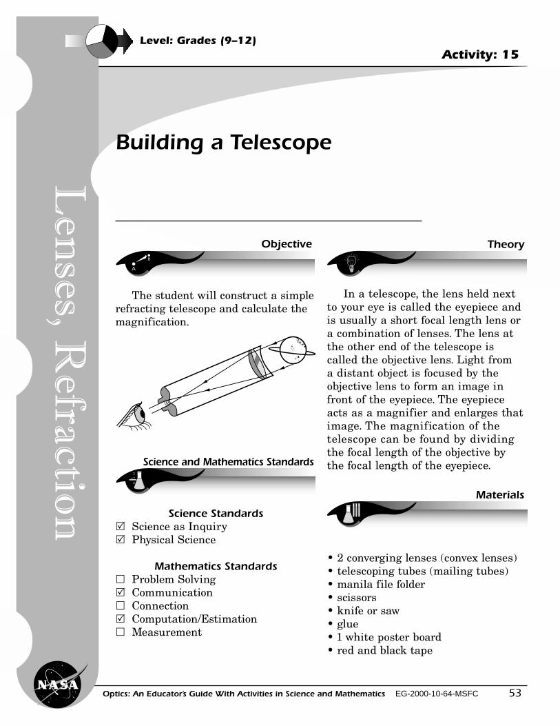
53Optics: An Educator’s Guide With Activities in Science and Mathematics EG-2000-10-64-MSFC
Level: Grades (9–12)Activity: 15
Building a Telescope
Theory
A
B
Objective
Science and Mathematics Standards
Materials
In a telescope, the lens held nextto your eye is called the eyepiece andis usually a short focal length lens ora combination of lenses. The lens atthe other end of the telescope iscalled the objective lens. Light froma distant object is focused by theobjective lens to form an image infront of the eyepiece. The eyepieceacts as a magnifier and enlarges thatimage. The magnification of thetelescope can be found by dividingthe focal length of the objective bythe focal length of the eyepiece.
• 2 converging lenses (convex lenses)• telescoping tubes (mailing tubes)• manila file folder• scissors• knife or saw• glue• 1 white poster board• red and black tape
The student will construct a simplerefracting telescope and calculate themagnification.
Science Standards� Science as Inquiry� Physical Science
Mathematics Standards� Problem Solving� Communication� Connection� Computation/Estimation� Measurement
Len
ses, Refractio
n
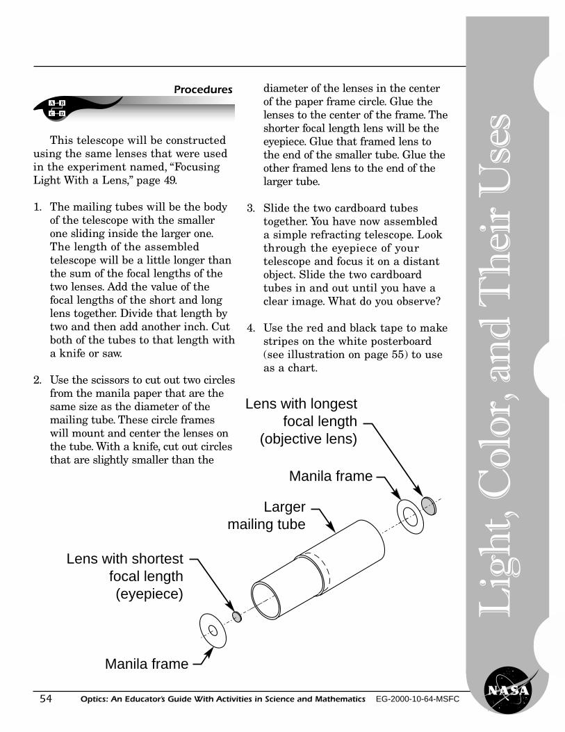
54
Lig
ht,
Col
or, a
nd
Th
eir
Use
s
Optics: An Educator’s Guide With Activities in Science and Mathematics EG-2000-10-64-MSFC
A B
C D
Procedures
This telescope will be constructedusing the same lenses that were usedin the experiment named, “FocusingLight With a Lens,” page 49.
1. The mailing tubes will be the bodyof the telescope with the smallerone sliding inside the larger one.The length of the assembledtelescope will be a little longer thanthe sum of the focal lengths of thetwo lenses. Add the value of thefocal lengths of the short and longlens together. Divide that length bytwo and then add another inch. Cutboth of the tubes to that length witha knife or saw.
2. Use the scissors to cut out two circlesfrom the manila paper that are thesame size as the diameter of themailing tube. These circle frameswill mount and center the lenses onthe tube. With a knife, cut out circlesthat are slightly smaller than the
diameter of the lenses in the centerof the paper frame circle. Glue thelenses to the center of the frame. Theshorter focal length lens will be theeyepiece. Glue that framed lens tothe end of the smaller tube. Glue theother framed lens to the end of thelarger tube.
3. Slide the two cardboard tubestogether. You have now assembleda simple refracting telescope. Lookthrough the eyepiece of yourtelescope and focus it on a distantobject. Slide the two cardboardtubes in and out until you have aclear image. What do you observe?
4. Use the red and black tape to makestripes on the white posterboard(see illustration on page 55) to useas a chart.
Largermailing tube
Lens with shortestfocal length(eyepiece)
Manila frame
Lens with longest focal length
(objective lens)
Manila frame
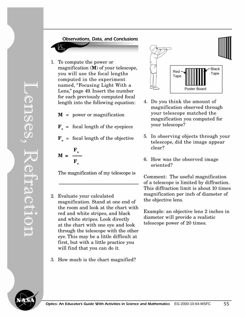
55Optics: An Educator’s Guide With Activities in Science and Mathematics EG-2000-10-64-MSFC
BlackTapeRed
Tape
Poster Board
2. Evaluate your calculatedmagnification. Stand at one end ofthe room and look at the chart withred and white stripes, and blackand white stripes. Look directlyat the chart with one eye and lookthrough the telescope with the othereye. This may be a little difficult atfirst, but with a little practice youwill find that you can do it.
3. How much is the chart magnified?
Observations, Data, and Conclusions
1. To compute the power ormagnification (M) of your telescope,you will use the focal lengthscomputed in the experimentnamed, “Focusing Light With aLens,” page 49. Insert the numberfor each previously computed focallength into the following equation:
M = power or magnification
Fe = focal length of the eyepiece
Fo = focal length of the objective
FoM = ——
Fe
The magnification of my telescope is
4. Do you think the amount ofmagnification observed throughyour telescope matched themagnification you computed foryour telescope?
5. In observing objects through yourtelescope, did the image appearclear?
6. How was the observed imageoriented?
Comment: The useful magnificationof a telescope is limited by diffraction.This diffraction limit is about 10 timesmagnification per inch of diameter ofthe objective lens.
Example: an objective lens 2 inches indiameter will provide a realistictelescope power of 20 times.
Len
ses, Refractio
n
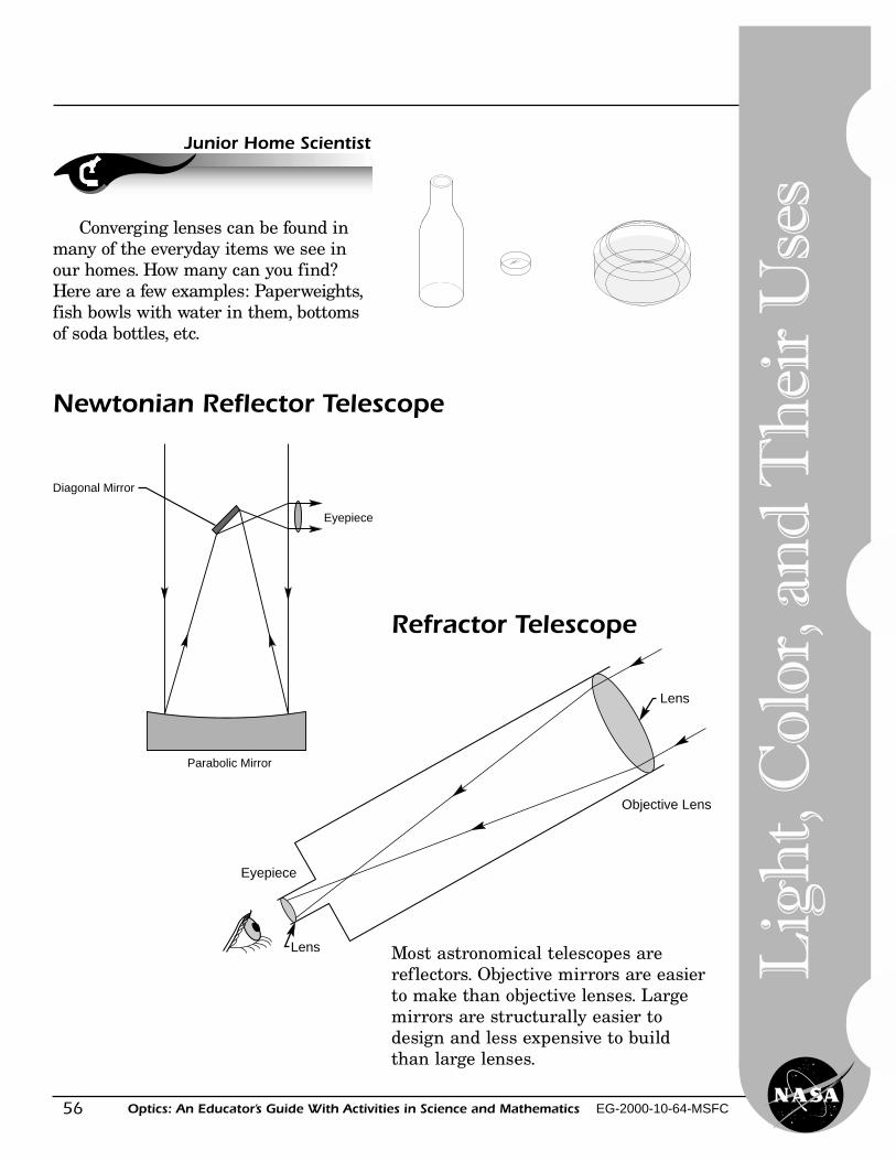
56
Lig
ht,
Col
or, a
nd
Th
eir
Use
s
Optics: An Educator’s Guide With Activities in Science and Mathematics EG-2000-10-64-MSFC
Converging lenses can be found inmany of the everyday items we see inour homes. How many can you find?Here are a few examples: Paperweights,fish bowls with water in them, bottomsof soda bottles, etc.
Junior Home Scientist
Diagonal Mirror
Eyepiece
Parabolic Mirror
Newtonian Reflector Telescope
Lens
Lens
Eyepiece
Objective Lens
Refractor Telescope
Most astronomical telescopes arereflectors. Objective mirrors are easierto make than objective lenses. Largemirrors are structurally easier todesign and less expensive to buildthan large lenses.
57Optics: An Educator’s Guide With Activities in Science and Mathematics EG-2000-10-64-MSFC
Building a Microscope
Level: Grades (9–12)Activity: 16
A
B
Objective
Science and Mathematics Standards
Theory
Materials
The student will construct a simplelow-power microscope from twoconverging lenses. See pages 59–62.The student will be able to see howa microscope works.
Science Standards� Science as Inquiry� Physical Science
Mathematics Standards� Problem Solving� Communication� Connection� Computation/Estimation� Measurement
In a microscope, the lens, placednext to the object to be magnified, iscalled the objective lens, while thelens held next to the eye is called theeyepiece. The eyepiece should have afocal length of about 25 millimeters,while the objective should have a focallength of 25 millimeters or less to besuitable for building a microscope.The distance to the enlarged imageformed by the objective lens is 160millimeters. The enlarged imageformed by the objective lens ismagnified by the eyepiece.
• 2 converging lenses (convex lenses)• telescoping tubes (mailing tubes)• a selection of materials to view with
the microscope• a laboratory microscope
Len
ses
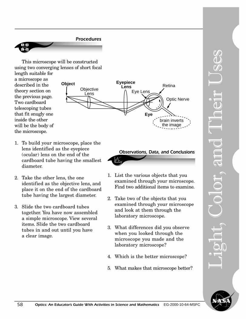
58
Lig
ht,
Col
or, a
nd
Th
eir
Use
s
Optics: An Educator’s Guide With Activities in Science and Mathematics EG-2000-10-64-MSFC
A B
C D
Procedures
This microscope will be constructedusing two converging lenses of short focallength suitable fora microscope asdescribed in thetheory section onthe previous page.Two cardboardtelescoping tubesthat fit snugly oneinside the otherwill be the body ofthe microscope.
1. To build your microscope, place thelens identified as the eyepiece(ocular) lens on the end of thecardboard tube having the smallestdiameter.
2. Take the other lens, the oneidentified as the objective lens, andplace it on the end of the cardboardtube having the largest diameter.
3. Slide the two cardboard tubestogether. You have now assembleda simple microscope. View severalitems. Slide the two cardboardtubes in and out until you havea clear image.
Observations, Data, and Conclusions
1. List the various objects that youexamined through your microscope.Find two additional items to examine.
2. Take two of the objects that youexamined through your microscopeand look at them through thelaboratory microscope.
3. What differences did you observewhen you looked through themicroscope you made and thelaboratory microscope?
4. Which is the better microscope?
5. What makes that microscope better?
ObjectObjective
Lens
Eyepiece Lens
Eye LensRetina
Optic Nerve
Eyebrain invertsthe image
59Optics: An Educator’s Guide With Activities in Science and Mathematics EG-2000-10-64-MSFC
Junior Home Scientist Construction of aMicroscope—A File Folder Microscope
Materials
• 2 lenses (one 46 mm and one 28 mm)• 2 manila file folders• carpenter’s wood glue• dowel• small wooden block• screw with wing nut• scissors• black liquid shoe polish or dye• rubber bands• small piece of pipe• clear varnish (optional)
1. From the manila file folder, cut thebiggest piece of uncreased paperpossible. Pull the piece of folderback and forth over the sharp edgeof a desk so that the paper willcurve or curl. After the entire pieceof folder has begun to curl, take thesmall piece of pipe and roll the paperaround it. As the paper is rolledonto the pipe apply the glue to theentire inside surface of the paper.When the first roll is complete, secureit with rubber bands until it is dry.
2. After the paper roll is dry, removethe pipe, and then drip blackliquid shoe polish inside the papertube to coat the entire insidesurface of the tube.
3. Next, cut a smaller piece of paperand roll and glue it around the firsttube of paper. (For all otherinstructions, see the illustration onthe following page.)
A B
C D
Procedures
Len
ses
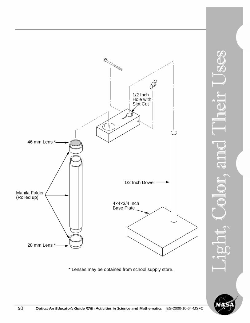
60
Lig
ht,
Col
or, a
nd
Th
eir
Use
s
Optics: An Educator’s Guide With Activities in Science and Mathematics EG-2000-10-64-MSFC
46 mm Lens *
28 mm Lens *
Manila Folder(Rolled up)
1/2 Inch Hole with Slot Cut
1/2 Inch Dowel
4×4×3/4 Inch Base Plate
* Lenses may be obtained from school supply store.
61Optics: An Educator’s Guide With Activities in Science and Mathematics EG-2000-10-64-MSFC
Interference Fringes
Level: Grades (9–12)Activity: 17
A
B
Objective
Science and Mathematics Standards
Theory
Materials
The student will observeinterference fringes formed by a layerof air between two pieces of glass.
Science Standards� Science as Inquiry� Physical Science
Mathematics Standards� Problem Solving� Communication� Connection� Computation/Estimation� Measurement
When light of a single color (orwavelength) passes through the layerof air between two flat pieces of glass,part of the light is reflected by the
glass-to-air boundary and part isreflected from the air-to-glass boundary.If the difference in the paths of thetwo rays is equal to a multiple ofwhole wavelengths, the light amplitudewill add to form a bright band. Thedark bands are formed by rays thatcancel each other. A good source oflight that has some single colors is afluorescent light. The light looks whiteto your eyes even though it contains abright green component caused by themercury vapor in the tube. This iscalled the mercury green line and hasa wavelength of 5,461 angstroms, whichis 0.5461 millimeters (0.5461 E–6 meters).See the illustration on page 62.
• 2 glass flats (glass microscope slides)(see List of Catalogs, page 83.)
• sheet of black construction paper• a light source such as an overhead
fluorescent light• 1 set high-quality flats (optional)
(see List of Catalogs, page 83.)
Interferen
ce Frin
ges
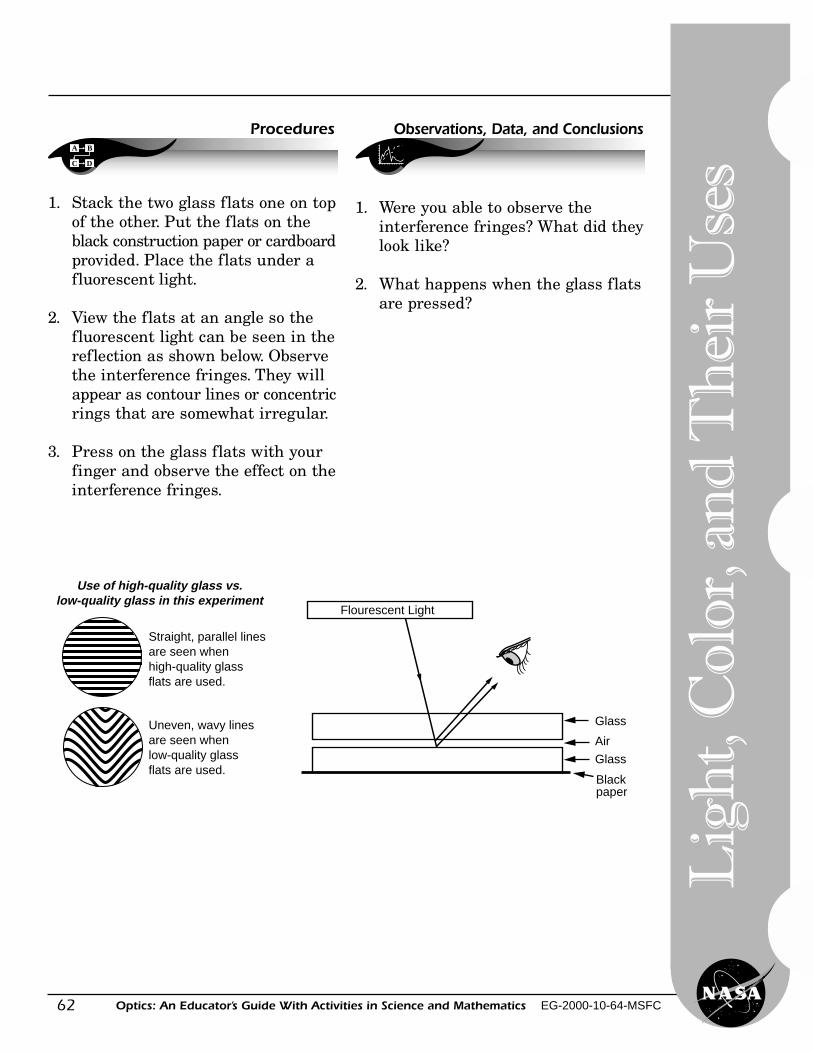
62
Lig
ht,
Col
or, a
nd
Th
eir
Use
s
Optics: An Educator’s Guide With Activities in Science and Mathematics EG-2000-10-64-MSFC
A B
C D
Procedures
1. Stack the two glass flats one on topof the other. Put the flats on theblack construction paper or cardboardprovided. Place the flats under afluorescent light.
2. View the flats at an angle so thefluorescent light can be seen in thereflection as shown below. Observethe interference fringes. They willappear as contour lines or concentricrings that are somewhat irregular.
3. Press on the glass flats with yourfinger and observe the effect on theinterference fringes.
Flourescent Light
Glass
Air
Glass
Blackpaper
Straight, parallel linesare seen when high-quality glass flats are used.
Uneven, wavy linesare seen when low-quality glass flats are used.
Use of high-quality glass vs.low-quality glass in this experiment
Observations, Data, and Conclusions
1. Were you able to observe theinterference fringes? What did theylook like?
2. What happens when the glass flatsare pressed?
63Optics: An Educator’s Guide With Activities in Science and Mathematics EG-2000-10-64-MSFC
Polarization of Light
Level: Grades (9–12)Activity: 18
A
B
Objective
Science and Mathematics Standards
Theory
Materials
If the electric field of light (atransverse wave) moves in a fixedplane, then the light is said to bepolarized in that plane. A polarizer
The student will observe polarizedlight and how it is affected when itpasses through stressed transparentplastic materials.
Science Standards� Science as Inquiry� Physical Science
Mathematics Standards� Problem Solving� Communication� Connection� Computation/Estimation� Measurement
made of film material will pass lightin only one plane. If we have twoPolarizing filters whose planes ofpolarization are rotated 90 degrees withrespect to each other, then no lightgets through. Some materials can rotatethe plane of polarization as light passesthrough them. If we place this materialbetween crossed polarizers, then somelight can get through. An example of amaterial that rotates the plane ofpolarization is clear plastic under stress.(Stress patterns can be produced byapplying a force to the plastic. They canalso be generated during themanufacturing process and frozeninto the plastic.)
• 2 sheets of Polarizing material for filters• small metal or cardboard frames• a light source such as a flourscent light• samples of flat molded plastic objects
such as a protractor• transparent tape
Po
larization
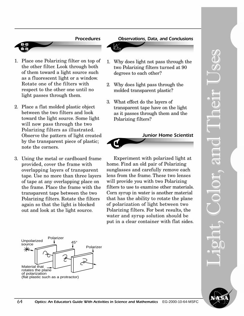
64
Lig
ht,
Col
or, a
nd
Th
eir
Use
s
Optics: An Educator’s Guide With Activities in Science and Mathematics EG-2000-10-64-MSFC
A B
C D
Procedures
1. Place one Polarizing filter on top ofthe other filter. Look through bothof them toward a light source suchas a fluorescent light or a window.Rotate one of the filters withrespect to the other one until nolight passes through them.
2. Place a flat molded plastic objectbetween the two filters and looktoward the light source. Some lightwill now pass through the twoPolarizing filters as illustrated.Observe the pattern of light createdby the transparent piece of plastic;note the corners.
3. Using the metal or cardboard frameprovided, cover the frame withoverlapping layers of transparenttape. Use no more than three layersof tape at any overlapping place onthe frame. Place the frame with thetransparent tape between the twoPolarizing filters. Rotate the filtersagain so that the light is blockedout and look at the light source.
Polarizer45°
Polarizer
Material that rotates the plane of polarization(flat plastic such as a protractor)
Unpolarizedsource
Observations, Data, and Conclusions
1. Why does light not pass through thetwo Polarizing filters turned at 90degrees to each other?
2. Why does light pass through themolded transparent plastic?
3. What effect do the layers oftransparent tape have on the lightas it passes through them and thePolarizing filters?
Junior Home Scientist
Experiment with polarized light athome. Find an old pair of Polarizingsunglasses and carefully remove eachlens from the frame. These two lenseswill provide you with two Polarizingfilters to use to examine other materials.Corn syrup in water is another materialthat has the ability to rotate the planeof polarization of light between twoPolarizing filters. For best results, thewater and syrup solution should beput in a clear container with flat sides.
65Optics: An Educator’s Guide With Activities in Science and Mathematics EG-2000-10-64-MSFC
Answer Booklet
Reflection of Light With a Plane (Flat) Mirror—Trace a StarObservations, Data, and Conclusions
Page 16
1. The individual students will complete the activity with varying degrees of difficulty.
2. The student will see the images reversed left to right.
3. The brain and the senses, especially touch, tend to get confused and the brainwill try to correct for the reversal of the images.
4. The hand will appear to be located behind the mirror at a distance equal to thedistance of the object from the front of the mirror.
5. It tends to be easier to trace with a finger because the body gets additionalfeedback through the sense of touch.
6. This activity deals with reflection.
7. At the end of the lesson, the students might share their designs with the class.If a computer is available the students could design and compile a booklet ofclass designs on the computer.
Reflection of Light With Two Plane Mirrors—Double Mirrors Placed at a 90-Degree Angle
Observations, Data, and ConclusionsPage 18
1. When the mirrors are placed at 90 degrees, the image is not reversed and thisis called a true image.
2. The eyes see a true image or they see the student as other people see the student.
3. Over the years, the student has adjusted to a reversed image in the mirror. Also,the activities ask the student to use the hand to cross midline of the body. Theright brain controls the left side and the left brain controls the left side and thisadds another variable which the student must consider.
4. Reflection
Teach
er’s Reso
urce
66
Lig
ht,
Col
or, a
nd
Th
eir
Use
s
Optics: An Educator’s Guide With Activities in Science and Mathematics EG-2000-10-64-MSFC
Reflection of Light With Two Plane Mirrors—Double Mirrors Placed at a Number of Angles
Observations, Data, and ConclusionsPage 20
1. Computation.
2. You will see whole images at 60, 90, and 180 degrees.
3. The number of images and the number of mirror frames that are reflected willbe equal.
4. The number of images equals 360 degrees divided by the angle indicated on theprotractor.
5. The number of observed images and the computed images should be equal, butthe observed images may be one or two less because of the crude equipmentused.
Making a KaleidoscopeObservations, Data, and Conclusions
Page 24
1. There is no exact number of images because the equipment being used is verycrude. The activity is included to encourage the student to observe more carefully.
2. The objects appear to be the same size, but they are reflected in parts or pieces.
3. In some segments of the kaleidoscope, the images are reversed left to right oreven upside down.
Making a PeriscopeObservations, Data, and Conclusions
Page 28
1. The lines are the same as those shown in the illustration at the top of page 17.
2. No, the periscope will not function if the mirrors are positioned at different angles.
67Optics: An Educator’s Guide With Activities in Science and Mathematics EG-2000-10-64-MSFC
Exploring Diffraction With a SpectroscopeObservations, Data, and Conclusions
Page 32
1. The student will see a spectrum or bands of color like a rainbow. Each bulb willalso have a set of distinct vertical lines. Each different element has its owndistinct set of vertical lines, or signature.
2. If the light observed is a white light source, the student will observe the sevenmajor colors in a continuous spectrum. The name Roy G. Biv will help thestudent to remember the names of the colors in order—red, orange, yellow,green, blue, indigo, and violet. If the light observed is not a white light source,some of the colors of the spectrum will not be seen.
3. The bands of color fade or blend into each other. Depending on the spectroscope,the student may observe very distinct vertical lines of color. You might also seesome black lines which are absorption lines.
4. No, each light source has its own unique pattern of colored vertical lines.
5. There are bands of color, but they also tend to fade together. With somespectroscopes, the students will see very distinct and precisely spaced verticallines. These lines are the signature of that particular element. The black lines(Fraunhofer lines) are the absorption lines of certain elements. For moreinformation, see an encyclopedia.
6. Though light bulbs may look the same, they are filled with differentelements or gases. Each gas or element has its own emission spectrum orbands of colors.
Diffraction of Light by Very Small AperturesObservations, Data, and Conclusions
Page 36
1. This activity is intended to encourage the student to observe more carefully.
2. The shape, direction, or number of pattern may change as the screen is slowlyrotated. A varying combination of patterns and colors will appear.
Teach
er’s Reso
urce
68
Lig
ht,
Col
or, a
nd
Th
eir
Use
s
Optics: An Educator’s Guide With Activities in Science and Mathematics EG-2000-10-64-MSFC
Discovering Color With a PrismObservations, Data, and Conclusions
Pages 38
1. By refraction, a prism can break white light up into its seven major colors.Some of the suggested light sources will appear to be white light to the eye,but a prism will show that some wavelengths are not present.
2. The acrylic plastic or plastic prism will refract and break the light into color, butthe quality of the plastic or glass will determine the sharpness of the colors.
3. Colors always come out of a prism in the same order. Some colors will be omittedif the light source is not white light.
4. The colors blend or shade into each other.
5. The bands of color do not always have the same shape or width. The shape orwidth of the color band depends on the type of light source.
Light and Color—Color SpinnersObservations, Data, and Conclusions
Page 42
1. The colors seem to blend and form other colors. The perception of color isdetermined by light, the source of color; material and its response to color;and the eye of the perceiver of color.
2. The colors seen by the student will depend on the design, the kind of pigmentused, and the speed of the movement.
3. While spinning, the colors seem to mix and become other colors. The mixingof the colors is a function of the eyes and brain.
4. Combine blue and yellow pigments to make green.
5. Combine red and yellow pigment to make orange.
6. If all colors are equally combined in design, they should make white or gray.The kind of pigment used will affect the colors.
7. Most of the time, brown can be made by adding red, yellow, and blue.
8. Color one side of the circle and add a few lines or dots on the other halfof the circle. Experiment.
69Optics: An Educator’s Guide With Activities in Science and Mathematics EG-2000-10-64-MSFC
9. Color varies a great deal with the type of pigment used. The colors in light alsocombine differently than pigment.
Light and Color—FiltersObservations, Data, and Conclusions
Page 44
1. The students will record what they observe. Answers will vary depending onthe filters used.
2. Answers will vary.
3. Answers will vary.
4. Filters subtract or absorb some colors. Two filters may be used to transmita third color.
Light and Color—Hidden MessagesObservations, Data, and Conclusions
Page 46
1. The student should see a confusion of lines, letters, and shapes of varying colors.
2. If a red filter is used, red will not be seen and yellow may appear to be orange.Green will appear to be dark blue. If a yellow filter is used, all the yellow designswill not be seen. The colors will vary with the pigments and filters used.
3. Answers will vary depending on the pigment and filters used.
4. Each filter absorbs and transmits different wavelengths of light.
5. A booklet of secret messages might be a nice class project.
Simple MagnifiersObservations, Data and Conclusions
Page 48
1. The letters are magnified.
2. The magnification is better with smaller drops of water.
3. The water drop magnifier is focused by moving it back and forth fromthe surface of the print or picture.
Teach
er’s Reso
urce
70
Lig
ht,
Col
or, a
nd
Th
eir
Use
s
Optics: An Educator’s Guide With Activities in Science and Mathematics EG-2000-10-64-MSFC
4. The smaller water drop magnifies more because of the way it bends or refractslight. The focal length of the small drop is shorter because the curvature of thesurface of the water drop is greater. The shorter the focal length of a lens, thegreater the magnification.
5. Bottles with curved edges magnify better.
6. The bottom or curved side of a bottle magnifies best.
7. The water acts as a lens and refracts or bends light to a focal point.
8. Some bottles serve as converging or convex lenses, and they bend or refractthe light to focus it.
Focusing Light With a LensObservations, Data, and Conclusions
Pages 50 (Part 1)
1. Answers will vary depending on the lenses provided.
2. Answers will vary depending on the lenses provided.
3. The lens of the eyepiece of a telescope will have the shorter focal length and thegreater magnification. The object lens will have the longer focal length and lessmagnification.
Pages 51–52 (Part 2)
1. Answers will vary depending on the lenses provided.
2. With a single lens, the focal image will generally be smaller than the object.The focal image may be the same size as the object, but it will never be larger.
3. If you found two distinct images, one will be large and one will be small. Onemay also be reversed. There are two distinct images because the object distanceis different. The object distance is the distance between the object and the lens.The student must consistently use the same object distance whenmeasurements are made.
4. Answers will vary depending on the lenses provided.
71Optics: An Educator’s Guide With Activities in Science and Mathematics EG-2000-10-64-MSFC
Building a TelescopeObservations, Data, and Conclusions
Pages 55
1. Answers will vary with the lenses used.
2. The student will observe with and without the telescope. After observing thestriped chart, or some other object provided, the student will make a judgmentabout the amount the telescope magnifies. Generally, simple telescopesconstructed by students will have a magnification of less than five.
3. Answers will vary with the lenses used.
4–5. These questions were included to encourage the student to observe carefully.
6. This is a refracting telescope and the image will appear upside down. For moreinformation, see telescopes in an encyclopedia.
Building a MicroscopeObservations, Data, and Conclusions
Page 58
1–2. Answers will vary.
3. The microscope with the better set of lenses will have a clearer, sharper image.
4. The purchased microscope will be better.
5. The purchased microscope is better because the glass in the lenses is a betterquality and has been ground and polished more carefully. It is also mounted andaligned more precisely.
Interference FringesObservations, Data, and Conclusions
Page 62
1. See the top left figure on page 62.
2. See the bottom left figure on page 62.
Teach
er’s Reso
urce
72
Lig
ht,
Col
or, a
nd
Th
eir
Use
s
Optics: An Educator’s Guide With Activities in Science and Mathematics EG-2000-10-64-MSFC
Polarization of LightObservations, Data, and Conclusions
Page 64
1. Polarized material allows light to pass through it only in one direction or plane.See the figure on page 64.
2. The plastic is transparent and it will allow the light to pass through it, butthe student should notice the bands of color around areas of stress. As theobject was molded into shape, there were areas that were pulled and pushed,and these stress marks were molded into the plastic. The stressed areasinterrupt the light rays entering the plastic and change the plane ordirection of that light.
3. The transparent tape changes the plane or direction of polarization. The tapemay also act as a filter and absorb some wavelengths. Layering the tape mayalso reinforce the light waves that are in or out of phase. Two or more lightwaves that exactly match or overlap at the crests and troughs of the waves aresaid to be in phase. When the crests and troughs of two or more waves do notmatch or overlap, the waves are said to be “out of phase.”
73Optics: An Educator’s Guide With Activities in Science and Mathematics EG-2000-10-64-MSFC
Glossaryadditive color
A primary light color—red, blue, or green; these three colors produce white light whenadded together.
angle of incidenceThe angle between a wave striking a barrier and the line perpendicular to the surface.
angle of reflectionThe angle between a reflected wave and the normal to the barrier from which it is reflected.
angstromAn angstrom is 1/100,000,000 of a centimeter.
concave lensA lens that is thinner in the middle than at the edges; used to correct nearsightedness.
convex lensA lens that is thicker in the middle than at the edges; used to correct farsightedness.
diffraction gratingA piece of transparent or reflecting material, which contains many thousands of parallellines per centimeter; used to produce a light spectrum by diffraction.
electromagnetic waveA wave that does not have to travel through matter in order to transfer energy.
electromagnetic spectrumTransverse radiant energy waves, ranging from low frequency to very high frequency,which can travel at the speed of light.
elementA substance that cannot be broken down into simpler substances by ordinary means.
equalateral triangleA triangle with three equal angles of 60 degrees and sides of equal length.
filterA screen that allows only certain colors to pass through it; a transparent material thatseparates colors of light.
focal lengthThe distance between the principal focus of a lens or mirror and its optical center.
Teach
er’s Reso
urce
74
Lig
ht,
Col
or, a
nd
Th
eir
Use
s
Optics: An Educator’s Guide With Activities in Science and Mathematics EG-2000-10-64-MSFC
focal point/focusThe point that all light rays from a mirror or lens pass through.
frequencyThe number of waves that pass a point in a given unit of time.
gamma rayHigh-energy wave of high frequency and with a wavelength shorter than an x ray; releasedin a nuclear reaction.
imageThe reproduction of an object formed with lenses or mirrors.
in phaseWhen two or more light rays overlap exactly at the crest and the trough, they are said to be“in phase.”
index of refractionThe amount that light is refracted when it enters a substance; given as the ratio of speedof light in a vacuum to its speed in a given substance.
infrared radiationInvisible radiation with a longer wavelength than red light and next to red light in theelectromagnetic spectrum; used in heat lamps, to detect heat loss from buildings, and todetect certain tumors.
interferenceThe addition by crossing wave patterns of a loss of energy in certain areas and reinforcementof energy in other areas.
kaleidoscopeA toy in which reflections from mirrors make patterns. It was invented in 1819by David Brewster.
laser (light amplification by stimulated emission of radiation)A device that produces a highly concentrated, powerful beam of light which is all onefrequency or color and travels only in one direction.
law of reflectionAngle of incidence equals the angle of reflection.
lensA curved, transparent object; usually made of glass or clear plastic and used to direct light.
75Optics: An Educator’s Guide With Activities in Science and Mathematics EG-2000-10-64-MSFC
lightLight is a form of energy, traveling through the universe in waves. The wavelengths of visiblelight range from less than 4,000 angstroms to more than 7,000 angstroms.
normalA line perpendicular to a surface.
opaqueNot transparent; no light passes through the material.
optical axisThe line straight out from the center of a parabolic mirror; straight line through the center ofa lens.
optical fiberA thin strand of glass that transmits light down its length.
optical telescopeA tube with magnifying lenses or mirrors that collect, transmit, and focus light.
out of phaseWhen the crest of one wave overlaps the trough of another they are said to be “out of phase.”
parabolaA curved line representing the path of a projectile; the shape of the surface of aparabolic mirror.
parabolic mirrorA curved mirror.
pigmentA material that absorbs certain colors of light and reflects other colors.
plane mirrorA mirror with a flat surface.
polarized lightLight in which all waves are vibrating in a single plane.
prismA transparent material with two or more straight faces at an angle to each other.
real imageAn image that can be projected onto a screen; formed by a parabolic mirror or convex lens.
Teach
er’s Reso
urce
76
Lig
ht,
Col
or, a
nd
Th
eir
Use
s
Optics: An Educator’s Guide With Activities in Science and Mathematics EG-2000-10-64-MSFC
reflectionThe light or image you see when light bounces off a surface; bouncing a wave or ray off a surface.
reflecting telescopeA telescope in which magnification is produced by a parabolic mirror.
refractionBending of a wave or light ray caused by a change in speed as it passes at an angle from onesubstance into another.
scatteringThe spreading out of light by intersecting objects, whose size is near the wavelength.
sphericalSurface of a lens or mirror that is part of a sphere.
subtractive colorOne of the three pure pigment colors—magenta, yellow, cyan; these pigment colors produceblack when mixed.
translucentSemitransparent; a material that admits some light.
transparentSee-through; light can go through.
true imageA true image is the way other people see us. It is the opposite of the image that is seen in amirror.
ultraviolet radiationRadiation that has a shorter wavelength than visible light; next to violet light in theelectromagnetic spectrum.
virtual imageAn image formed by a mirror or lens that cannot be projected onto a surface.
visible light spectrumBand of visible colors produced by a prism when white light is passed through it.
wavelengthThe total linear length of one wave crest and trough.
x rayInvisible electromagnetic radiation of great penetrating power.
77Optics: An Educator’s Guide With Activities in Science and Mathematics EG-2000-10-64-MSFC
NASA Resources for Educators
NASA Educational Materials
NASA publishes a variety of education resources suitable for classroom use. Educational materialsare available from the NASA Educators’ Resource Center Network (ERCN). Posters, lithographs,and some other printed materials are in limited supplies; the publication of new materials isongoing. Contact the Educator Resource Center in your area, or NASA Central Operation ofResources for Educators (CORE), for the current list of available resources. (See next page forCORE and ERCN addresses.)
NASA Television
NASA Television (NTV) features Space Shuttle mission coverage, live special events, liveinteractive educational shows, electronic field trips, aviation and space news, and historicalNASA footage. Programming has a 3-hour block-Video (News) File, NASA Gallery, andEducation File beginning at noon Eastern and repeated three more times throughout the day.
The NASA Education File features programming for educators and students highlightingscience, mathematics, geography, and technology-related topics. Viewers are encouraged totape the programs.
The NTV Education File can be accessed athttp://spacelink.nasa.gov/education.file
Via satellite—GE2, Satellite, Transponder 9C at 85 degrees West longitude, verticalpolarization, with a frequency of 3880.0 megahertz (MHz) and audio of 6.8 MHz—orthrough collaborating distance learning networks and local cable providers.
Please visithttp://www.nasa.gov/ntv/ntvweb.htmlto learn about NTV on the web.
Live feeds preempt regularly scheduled programming. Check the internet for program listings at:
NTV Home Page:http://www.nasa.gov/ntv
Select “Today at NASA” and “What’s New on NASA TV”:http://www.nasa.gov
Select “TV Schedules”:http://spacelink.nasa.gov/NASA.News/
Teach
er’s Reso
urce
78
Lig
ht,
Col
or, a
nd
Th
eir
Use
s
Optics: An Educator’s Guide With Activities in Science and Mathematics EG-2000-10-64-MSFC
NASA Educator Resource Center Network
To make additional information available to the education community, the NASA EducationDivision has created the NASA Educator Resource Center (ERC) network. ERC’s contain awealth of information for educators: Publications, reference books, slide sets, audio cassettes,videotapes, telelecture programs, computer programs, lesson plans, and teacher guides withactivities. Because each NASA Field Center has its own areas of expertise, no two ERC’s areexactly alike. Phone calls are welcome if you are unable to visit the ERC that serves yourgeographic area. A list of the centers and the geographic regions they serve starts on the next page.
Regional Educator Resource Centers (RERC’s) offer more educators access to NASA educationalmaterials. NASA has formed partnerships with universities, museums, and other educationalinstitutions to serve as RERC’s in many states.
Teachers may preview, copy, or receive NASA materials at these sites. A complete list of RERC’sis available through CORE.
ERC and regional ERC locations:http://spacelink.nasa.gov/ercn
NASA CORE was established for the national and international distribution of NASA-producededucational materials in audiovisual format. Educators can obtain a catalog and an order form byone of the following methods:
• NASA CORE Lorain County Joint Vocational School 15181 Route 58 South Oberlin, OH 44074• Phone (440) 774–1051, Ext. 249 or 293• Fax (440) 774–2144• E-mail: [email protected]• Home Page: http://core.nasa.gov
79Optics: An Educator’s Guide With Activities in Science and Mathematics EG-2000-10-64-MSFC
If you live in: Precollege Officer: Educator Resource Center:
Alaska Mr. Garth A. Hull NASA Research Center:Arizona Special Assistant, Educational Programs NASA Ames Educator Resource CenterCalifornia NASA Ames Research Center NASA Ames Research CenterHawaii Mail Stop 204–12 Mail Stop 253–2Idaho Moffett Field, CA 94035–1000 Moffett Field, CA 94035–100Montana Phone: (650) 604–5543 Phone: (650) 604–3574NevadaOregonUtahWashingtonWyoming
California Dr. Marianne McCarthy NASA Dryden Flight Research Center:(Regions near Education Specialist NASA Dryden EducatorNASA Dryden NASA Dryden Flight Research Center Resource CenterFlight Research Mail Stop D4839A 45108 N. 3rd Street EastCenter) P.O. Box 273 Lancaster, CA 93535
Edwards, CA 93523–0273 Phone: (661) 948–7347Phone: (661) 258–2281
Connecticut Dr. Robert Gabrys NASA Goddard Space Flight Center:Delaware Chief, Education Office NASA Goddard EducatorDistrict of Columbia NASA Goddard Space Flight Center Resource CenterMaine Mail Code 130.3 Mail Code 130.3Maryland Greenbelt, MD 20771–0001 NASA Goddard Space Flight CenterMassachusetts Phone: (301) 286–7207 Greenbelt, MD 20771–0001New Hampshire Phone: (301) 286–8570New JerseyNew YorkPennsylvaniaRhode IslandVermont
Colorado Ms. Billie A. Deason NASA Johnson Space Center:Kansas Education Team Lead NASA JSC Educator Resource CenterNebraska Education & Community 1601 NASA Road OneNew Mexico Support Branch Houston, TX 77058–3696North Dakota NASA Johnson Space Center Phone: (281) 244–2129Oklahoma Mail Code AP2South Dakota 2101 NASA Road OneTexas Houston, TX 77058–3696
Phone: (281) 483–8646
Teach
er’s Reso
urce
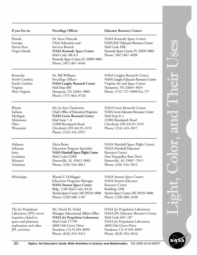
80
Lig
ht,
Col
or, a
nd
Th
eir
Use
s
Optics: An Educator’s Guide With Activities in Science and Mathematics EG-2000-10-64-MSFC
If you live in: Precollege Officer: Educator Resource Center:
Florida Dr. Steve Dutczak NASA Kennedy Space Center:Georgia Chief, Education and NASA KSC Educator Resource CenterPuerto Rico Services Branch Mail Code ERCVirgin Islands NASA Kennedy Space Center Kennedy Space Center, FL 32899–0001
Mail Code AB–G1 Phone: (407) 867–4090Kennedy Space Center, FL 32899–0001Phone: (407) 867–4444
Kentucky Dr. Bill Williams NASA Langley Research Center:North Carolina Precollege Officer NASA Langley Educator Resource CenterSouth Carolina NASA Langley Research Center Virginia Air and Space CenterVirginia Mail Stop 400 Hampton, VA 23669–4033West Virginia Hampton, VA 23681–0001 Phone: (757) 727–0900 Ext.757
Phone: (757) 864–9728
Illinois Ms. Jo Ann Charleston NASA Lewis Research Center:Indiana Chief, Office of Education Programs NASA Lewis Educator Resource CenterMichigan NASA Lewis Research Center Mail Stop 8–1Minnesota Mail Stop 7–4 21000 Brookpark RoadOhio 21000 Brookpark Road Cleveland, OH 44135–3191Wisconsin Cleveland, OH 44135–3191 Phone: (216) 433–2017
Phone: (216) 433–2957
Alabama Alicia Beam NASA Marshall Space Flight Center:Arkansas Education Program Specialist NASA Marshall EducatorIowa NASA Marshall Space Flight Center Resource CenterLouisiana Mail Code CD60 One Tranquility Base DriveMissouri Huntsville, AL 35812–0001 Huntsville, AL 35807–7015Tennessee Phone: (256) 544–8811 Phone: (256) 544–5812
Mississippi Wanda F. DeMaggio NASA Stennis Space Center:Education Programs Manager NASA Stennis EducatorNASA Stennis Space Center Resource CenterBldg. 1100 Mail Code AA10 Building 1200Stennis Space Center, MS 39529–6000 Stennis Space Center, MS 39529–6000Phone: (228) 688–1107 Phone: (228) 688–3338
The Jet Propulsion Mr. David M. Seidel NASA Jet Propulsion Laboratory:Laboratory (JPL) serves Manager, Educational Affairs Office NASA JPL Educator Resource Centerinquiries related to NASA Jet Propulsion Laboratory Mail Code 601–107space and planetary Mail Code T1709 NASA Jet Propulsion Laboratoryexploration and other 4800 Oak Grove Drive 4800 Oak Grove DriveJPL activities. Pasadena, CA 91109–8099 Pasadena, CA 91109–8099
Phone: (818) 354–9313 Phone: (818) 354–6916
81Optics: An Educator’s Guide With Activities in Science and Mathematics EG-2000-10-64-MSFC
On-Line Resources for Educators
NASA Education Home Page
NASA’s Education Home Page serves as a cyber-gateway to information regarding educationalprograms and services offered by NASA for educators and students across the United States. Thishigh-level directory of information provides specific details and points of contact for all of NASA’seducational efforts and Fields Center offices.
Educators and students utilizing this site will have access to a comprehensive overview of NASA’seducational programs and services, along with a searchable program inventory that has catalogedNASA’s educational programs.
NASA Education Home Page:http://education.nasa.gov
NASA Spacelink
NASA Spacelink is one of NASA’s electronic resources specifically developed for the educationalcommunity. Spacelink is a “virtual library” in which local files and hundreds of NASA WorldWide Web links are arranged in a manner familiar to educators. Using the Spacelink searchengine, educators can search this virtual library to find information regardless of its locationwithin NASA. Special events, missions, and intriguing NASA web sites are featured in Spacelink’s“Hot Topics” and “Cool Picks” areas.
Spacelink may be accessed at: http://spacelink.nasa.gov
NASA Spacelink is the official home to electronic versions of NASA’s Educational Products. NASAeducator guides, educational briefs, lithographs, and other materials are cross-referenced throughoutSpacelink with related topics and events. A complete listing of NASA Educational Products can befound at the following address:
http://spacelink.nasa.gov/products
“Educator Focus” is comprised of a series of Spacelink articles, which offers helpful informationrelated to better understanding and using NASA educational products and services. Visit “EducatorFocus” at the following address:
http://spacelink.nasa.gov/focus
Join the NASA Spacelink EXPRESS mailing list to receive announcements of new NASAmaterials and opportunities for educators. Our goal is to inform you as quickly as possible whennew NASA educational publications become available on Spacelink:
http://spacelink.nasa.gov/express
Teach
er’s Reso
urce
82
Lig
ht,
Col
or, a
nd
Th
eir
Use
s
Optics: An Educator’s Guide With Activities in Science and Mathematics EG-2000-10-64-MSFC
NASA Aeronautics Centers’ Education Home Pages
NASA Marshall Space Flight Centerhttp://www.msfc.nasa.gov/education
NASA Ames Research Centerhttp://www.arc.nasa.gov/kids.html
NASA Dryden Flight Research Centerhttp://trc.dfrc.nasa.gov/trc/
NASA Langley Research Centerhttp://edu.larc.nasa.gov
NASA Lewis Research Centerhttp://www.grc.nasa.gov/www/oep
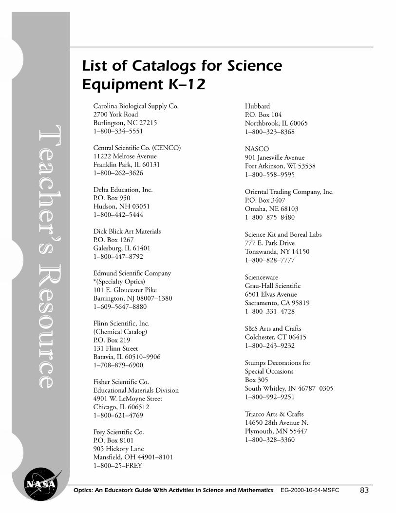
83Optics: An Educator’s Guide With Activities in Science and Mathematics EG-2000-10-64-MSFC
List of Catalogs for ScienceEquipment K–12
Carolina Biological Supply Co.2700 York RoadBurlington, NC 272151–800–334–5551
Central Scientific Co. (CENCO)11222 Melrose AvenueFranklin Park, IL 601311–800–262–3626
Delta Education, Inc.P.O. Box 950Hudson, NH 030511–800–442–5444
Dick Blick Art MaterialsP.O. Box 1267Galesburg, IL 614011–800–447–8792
Edmund Scientific Company*(Specialty Optics)101 E. Gloucester PikeBarrington, NJ 08007–13801–609–5647–8880
Flinn Scientific, Inc.(Chemical Catalog)P.O. Box 219131 Flinn StreetBatavia, IL 60510–99061–708–879–6900
Fisher Scientific Co.Educational Materials Division4901 W. LeMoyne StreetChicago, IL 6065121–800–621–4769
Frey Scientific Co.P.O. Box 8101905 Hickory LaneMansfield, OH 44901–81011–800–25–FREY
HubbardP.O. Box 104Northbrook, IL 600651–800–323–8368
NASCO901 Janesville AvenueFort Atkinson, WI 535381–800–558–9595
Oriental Trading Company, Inc.P.O. Box 3407Omaha, NE 681031–800–875–8480
Science Kit and Boreal Labs777 E. Park DriveTonawanda, NY 141501–800–828–7777
SciencewareGrau-Hall Scientific6501 Elvas AvenueSacramento, CA 958191–800–331–4728
S&S Arts and CraftsColchester, CT 064151–800–243–9232
Stumps Decorations forSpecial OccasionsBox 305South Whitley, IN 46787–03051–800–992–9251
Triarco Arts & Crafts14650 28th Avenue N.Plymouth, MN 554471–800–328–3360
Teach
er’s Reso
urce

84
Lig
ht,
Col
or, a
nd
Th
eir
Use
s
Optics: An Educator’s Guide With Activities in Science and Mathematics EG-2000-10-64-MSFC
Opt
ics–
An
Edu
cato
r’s G
uide
wit
h A
ctiv
itie
s in
Scie
nce,
Mat
hem
atic
s, a
nd T
echn
olog
y E
duca
tion
To a
chie
ve A
mer
ica’s
goa
ls in
Edu
cati
onal
Exc
elle
nce,
it is
NA
SA’s
mis
sion
tode
velo
p su
pple
men
tary
inst
ruct
iona
l mat
eria
ls a
nd c
urri
cula
in s
cien
ce, m
athe
mat
-ic
s, g
eogr
aphy
, and
tech
nolo
gy. N
ASA
see
ks to
invo
lve
the
educ
atio
nal c
omm
unit
yin
the
deve
lopm
ent a
nd im
prov
emen
t of t
hese
mat
eria
ls. Y
our
eval
uati
on a
ndsu
gges
tion
s ar
e vi
tal t
o co
ntin
ually
impr
ovin
g N
ASA
edu
cati
onal
mat
eria
ls.
Plea
se t
ake
a m
omen
t to
res
pond
to
the
stat
emen
ts a
nd q
uest
ions
bel
ow.
You
can
subm
it y
our
resp
onse
thr
ough
the
inte
rnet
or
by m
ail.
Send
you
rre
ply
to t
he fo
llow
ing
inte
rnet
add
ress
:
http
://e
hb2g
sfc.
nasa
.gov
/edc
ats/
educ
ator
_gui
de
You
will
then
be
aske
d to
ent
er y
our
data
at t
he a
ppro
pria
te p
rom
pt.
Oth
erw
ise,
ple
ase
retu
rn th
e re
ply
card
by
mai
l. T
hank
you
.
Ed
uca
tor
Rep
ly C
ard
1. W
ith
wha
t gra
des
did
you
use
the
educ
ator
’s gu
ide?
Num
ber
of T
each
ers/
Facu
lty:
____
__K
–4__
____
5–8
____
__9–
12__
____
Com
mun
ity C
olle
geC
olle
ge/U
nive
rsit
y:__
____
Gra
duat
e__
____
Und
ergr
adua
te
Num
ber
of S
tude
nts:
____
__K
–4__
____
5–8
____
__9–
12__
____
Com
mun
ity C
olle
geC
olle
ge/U
nive
rsit
y:__
____
Gra
duat
e__
____
Und
ergr
adua
te
Num
ber
of O
ther
s:__
____
Adm
inis
trat
ors/
Staf
f__
____
Pare
nts
____
__Pr
ofes
sion
al G
roup
s__
____
Gen
eral
Pub
lic__
____
Civ
ic G
roup
s__
____
Oth
er
2. W
hat i
s yo
ur h
ome
5- o
r 9-
digi
t zip
cod
e? _
_ __
__
__ _
_ -
__ _
_ __
__
3. T
his
is a
val
uabl
e ed
ucat
ors
guid
e.�
Str
ongl
y A
gree
� A
gree
� N
eutr
al�
Dis
agre
e�
Str
ongl
y D
isag
ree
4. I
exp
ect t
o ap
ply
wha
t I le
arne
d in
this
edu
cato
r’s g
uide
.�
Str
ongl
y A
gree
� A
gree
� N
eutr
al�
Dis
agre
e�
Str
ongl
y D
isag
ree
5. W
hat k
ind
of r
ecom
men
dati
on w
ould
you
mak
e to
som
eone
who
ask
s ab
out
this
edu
cato
r’s g
uide
?�
Exc
elle
nt�
Goo
d�
Ave
rage
� P
oor
� V
ery
Poor
6. H
ow d
id y
ou u
se th
is e
duca
tor’s
gui
de?
� B
ackg
roun
d In
form
atio
n�
Cri
tica
l Thi
nkin
g Ta
sks
� D
emon
stra
te N
ASA
Mat
eria
ls�
Dem
onst
rati
on�
Gro
up D
iscu
ssio
ns�
Han
ds-O
n A
ctiv
itie
s�
Int
egra
tion
Int
o E
xist
ing
Cur
ricu
la�
Int
erdi
scip
linar
y A
ctiv
ity
� L
ectu
re�
Sci
ence
and
Mat
hem
atic
s�
Tea
m A
ctiv
itie
s
Sta
ndar
ds I
nteg
rati
on�
Oth
er: P
leas
e sp
ecify
:
7. W
here
did
you
lear
n ab
out t
his
educ
ator
’s gu
ide?
� N
ASA
Edu
cato
r R
esou
rce
Cem
ter
� N
ASA
Cen
tral
Ope
rati
on o
f Res
ourc
es fo
r E
duca
tors
(C
OR
E)
� I
nsti
tuti
on/S
choo
l Sys
tem
� F
ello
w E
duca
tor
� W
orks
hop/
Con
fere
nce
� O
ther
: Ple
ase
spec
ify:
8. W
hat f
eatu
res
of th
is e
duca
tor’s
gui
de d
id y
ou fi
nd p
arti
cula
rly
help
ful?
9. H
ow c
an w
e m
ake
this
edu
cato
r’s g
uide
mor
e ef
fect
ive
for
you?
10. A
ddit
iona
l com
men
ts:
Toda
y’s
Dat
e:
Fold along the line and tape closed
EG
-200
0-10
-64-
MS
FC
Fold along the line and tape closed
National Aeronautics and Space AdministrationEducation DivisionMail Code FEWashington DC 20546-0001
Please PlaceStamp HerePost Office
Will Not DeliverWithout Proper
Postage