Embed Size (px)
Citation preview
EE 451
Power System Stability
Power system operates in synchronous mode
Power system is subjected to a wide range of disturbances
(small and large)
- Loads and generation changes
- Network changes
- Faults and outages of equipment
Hence, the stability of the power system will be affected.
Power system stability involves the study of the dynamics of
the power system under disturbances.
From the classical point of view, power system instability can
be seen as loss of synchronism (i.e., some synchronous
machines going out of step)when the system is subjected to a
particular disturbance.
CIGRE-IEEE Def. of Power System Stability:
Power system stability is the ability of an electric power
system, for a given initial operating condition, to regain a state
of operating equilibrium after being subjected to a physical
disturbance, with most system variables bounded so that
practically the entire system remains intact.
Stability involves study of dynamics of the system about an
equilibrium-initial operating condition.
Power system is highly non-linear system Stability study
study of non-linear dynamics of large system.
Stability (can be defined only in terms of)
Initial operating condition
Nature and magnitude of disturbance
Def. applies to an interconnected power system as a whole.
Most of the time we are interested in stability of a particular
generator or a group of generators
In our study we will focus on:
1- Steady-State Stability
2- Transient Stability
Steady state stability of power systems results from gradual
system changes.
Example: Gradual load increase as in the addition of MW at load
terminals or in gradual load decrease, as in steam change at the prime
mover power.
Power systems in general and alternators in particular have steady state
stability limit beyond which if subjected to gradual load changes will
loss steady state stability.
The power system is capable to resist the changes that occurs after the
disturbance and hence remain in stable form that is capable of
maintain equilibrium.
Example of sudden system changes (Transient Stability) are:
Fault occurrences, autoreclosure schemes, energization process of a
T.L. and de-energization of a T.L.
Recalling some definitions:
- Steady state stability is the ability of the power system network to
remain or to stay in equilibrium following a gradual system
change.
- Steady state stability limit is the maximum power transfer of that
system without loss of equilibrium.
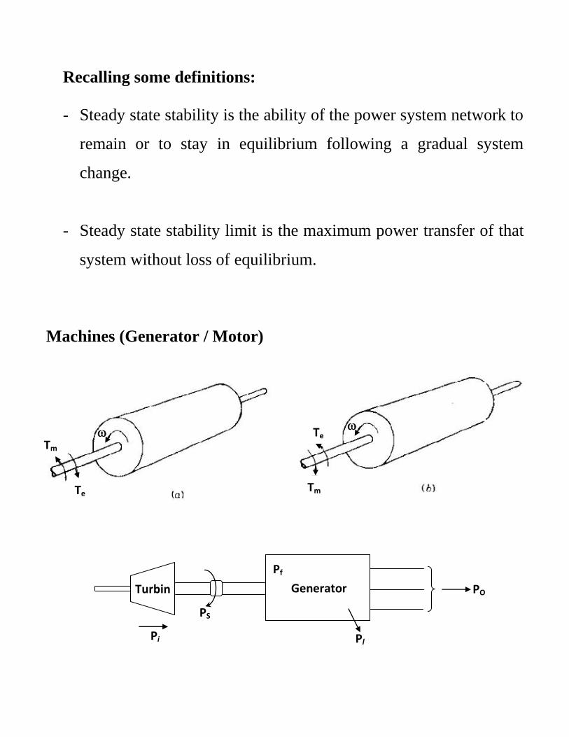
Machines (Generator / Motor)
PS
Pi
Pf
Pl
PO Turbin
e
Generator
Tm
Tm
Te
Te
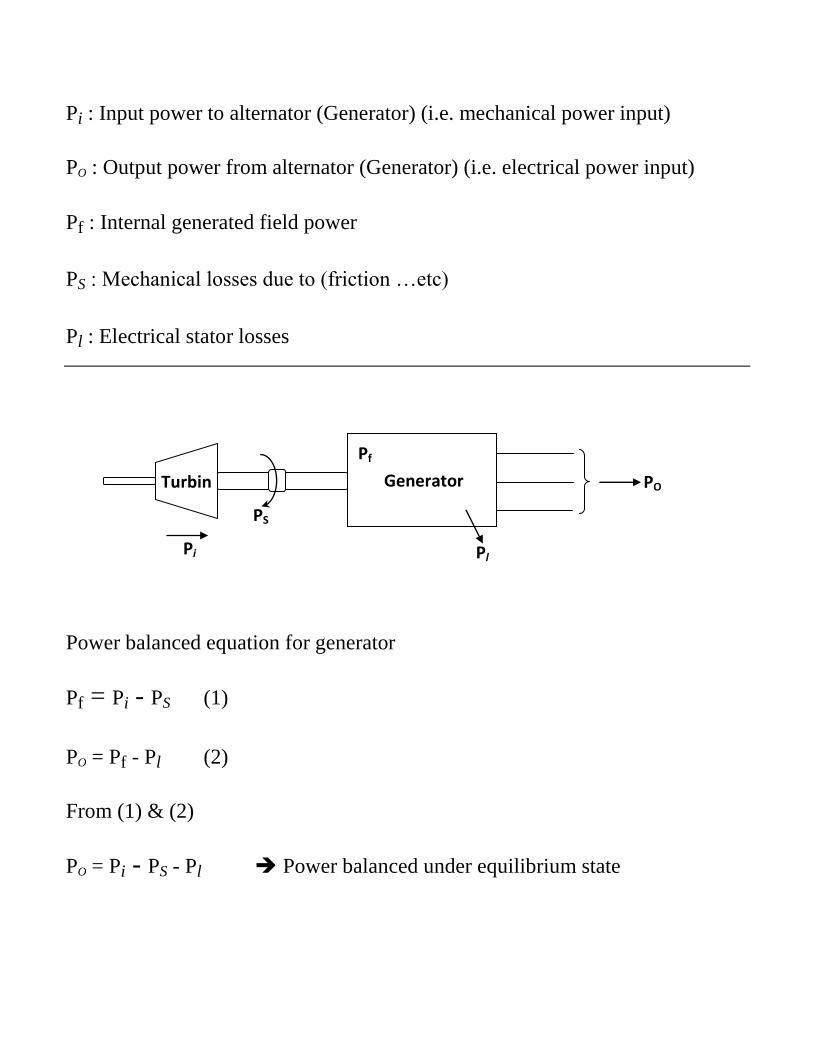
Pi : Input power to alternator (Generator) (i.e. mechanical power input)
PO : Output power from alternator (Generator) (i.e. electrical power input)
Pf : Internal generated field power
PS : Mechanical losses due to (friction …etc)
Pl : Electrical stator losses
Power balanced equation for generator
Pf = Pi - PS (1)
PO = Pf - Pl (2)
From (1) & (2)
PO = Pi - PS - Pl Power balanced under equilibrium state
PS
Pi
Pf
Pl
PO Turbin
e
Generator
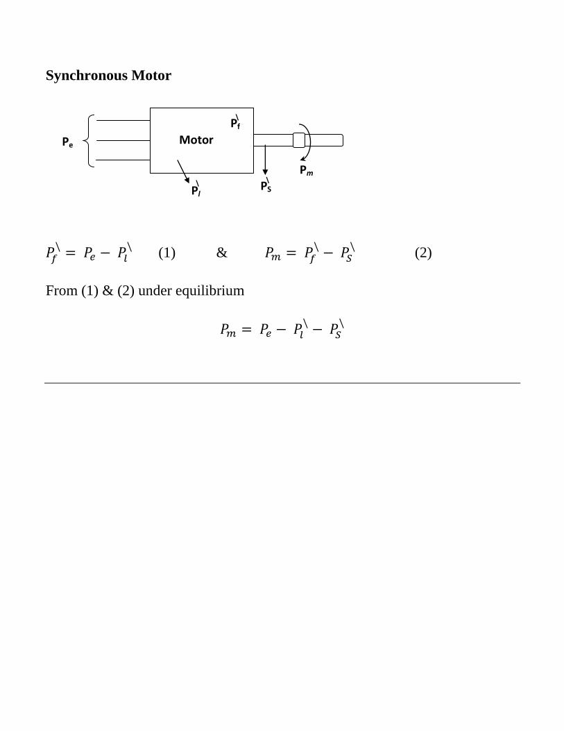
Synchronous Motor
(1) &
(2)
From (1) & (2) under equilibrium
PS Pm
Pf
Pl
Pe Motor
\ \
\
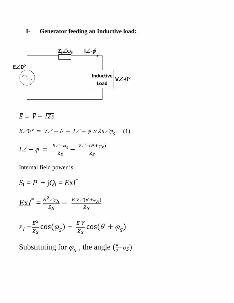
I- Generator feeding an Inductive load:
(1)
Internal field power is:
Sf = Pf + jQf = ExI*
ExI* =
Substituting for , the angle
Inductive
Load
E 0
Zs s I -
V -
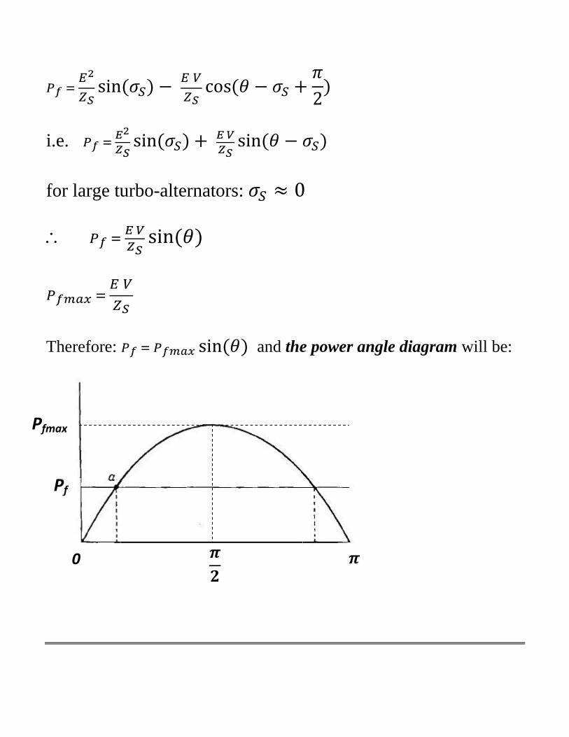
i.e.
for large turbo-alternators:
Therefore: and the power angle diagram will be:
Pf
Pfmax
0
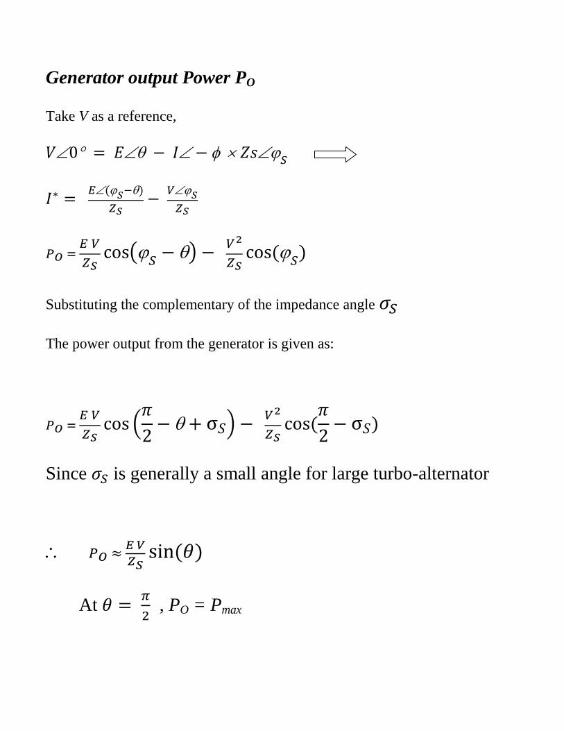
Generator output Power PO
Take V as a reference,
Substituting the complementary of the impedance angle
The power output from the generator is given as:
Since is generally a small angle for large turbo-alternator
At
, PO = Pmax
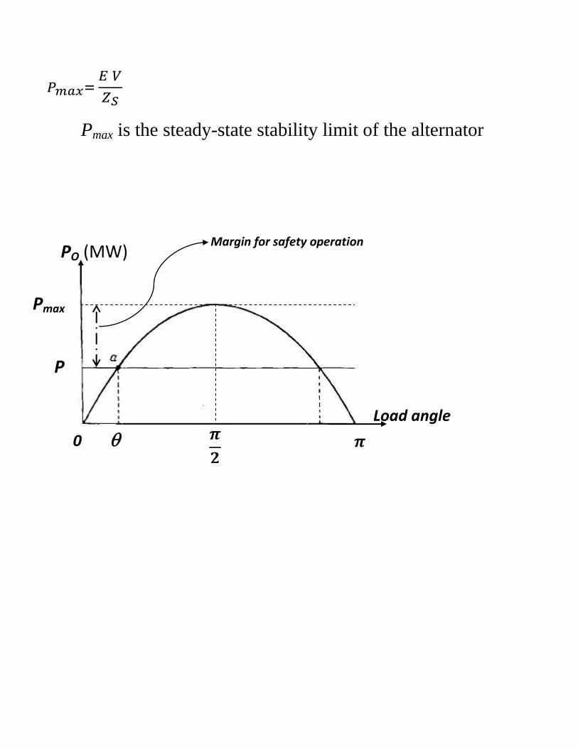
Pmax is the steady-state stability limit of the alternator
Pf
0
PO (MW)
Load angle
Margin for safety operation
Pmax
P
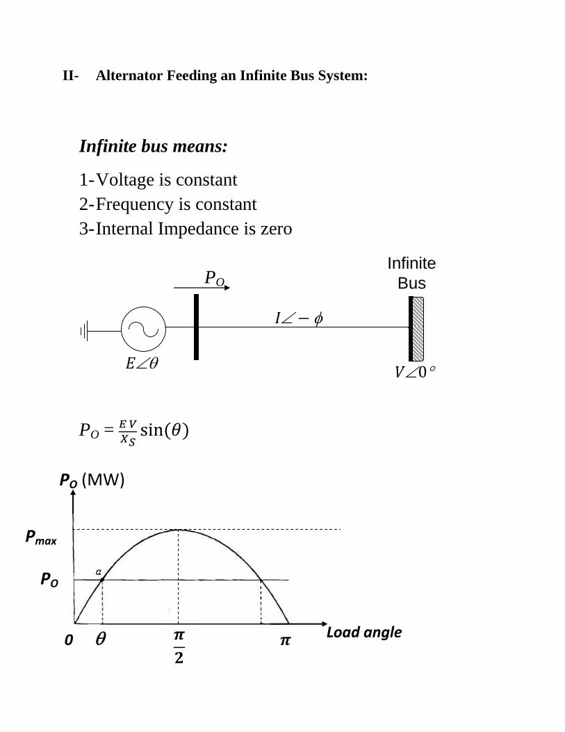
II- Alternator Feeding an Infinite Bus System:
Infinite bus means:
1- Voltage is constant
2- Frequency is constant
3- Internal Impedance is zero
Infinite
Bus
PO =
PO
PO
Pmax
0
PO (MW)
Load angle
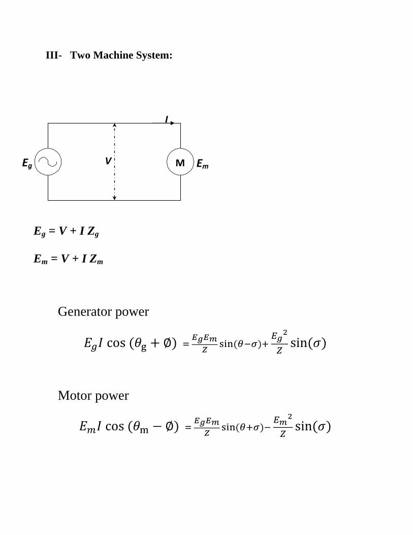
III- Two Machine System:
Eg = V + I Zg
Em = V + I Zm
Generator power
Motor power
V
I
M Em Eg
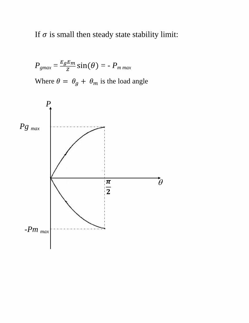
If is small then steady state stability limit:
Pgmax =
= - Pm max
Where is the load angle
-Pm max
Pg max
P
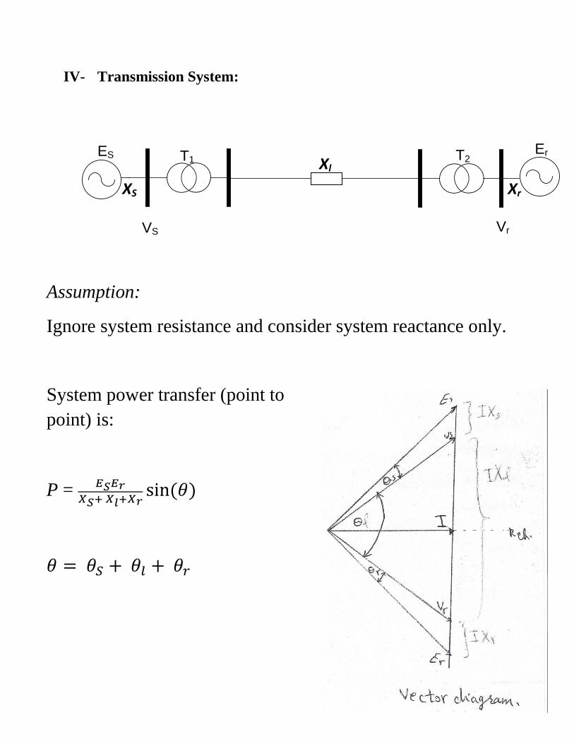
IV- Transmission System:
ES ErT1 T2
VS Vr
Assumption:
Ignore system resistance and consider system reactance only.
System power transfer (point to
point) is:
P =
Xl
XS Xr
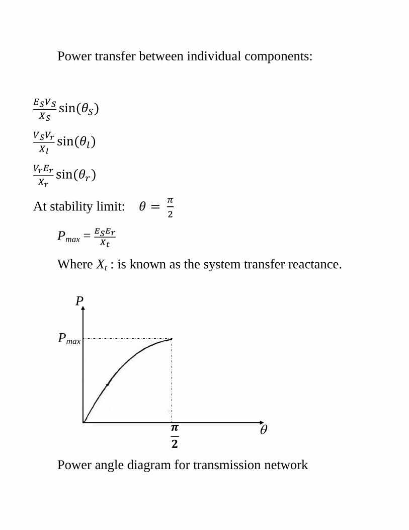
Power transfer between individual components:
At stability limit:
Pmax =
Where Xt : is known as the system transfer reactance.
Power angle diagram for transmission network
Pmax
P
Improvement of steady state stability limit
1- Improving excitation system
2- Reduce system transfer reactance
3- Parallel circuit arrangement
4- Series Compensation