Embed Size (px)
Citation preview

EE 245: Introduction to MEMSModule 8: Microstructural Elements
CTN 10/5/09
1Copyright © 2009 Regents of the University of California
EE C245 – ME C218Introduction to MEMS Design
F ll 2009Fall 2009
Prof. Clark T.-C. Nguyen
Dept. of Electrical Engineering & Computer SciencesUniversity of California at Berkeley
EE C245: Introduction to MEMS Design LecM 8 C. Nguyen 9/28/07 1
University of California at BerkeleyBerkeley, CA 94720
Lecture Module 8: Microstructural Elements
Outline
• Reading: Senturia, Chpt. 9• Lecture Topics:
Bending of beamsBending of beamsCantilever beam under small deflectionsCombining cantilevers in series and parallelFolded suspensionsDesign implications of residual stress and stress gradients
EE C245: Introduction to MEMS Design LecM 8 C. Nguyen 9/28/07 2

EE 245: Introduction to MEMSModule 8: Microstructural Elements
CTN 10/5/09
2Copyright © 2009 Regents of the University of California
Bending of Beams
EE C245: Introduction to MEMS Design LecM 8 C. Nguyen 9/28/07 3
Beams: The Springs of Most MEMS
• Springs and suspensions very common in MEMSCoils are popular in the macro-world; but not easy to make in the micro-worldBeams: simpler to fabricate and analyze; become p y“stronger” on the micro-scale → use beams for MEMS
EE C245: Introduction to MEMS Design LecM 8 C. Nguyen 9/28/07 4
Comb-Driven Folded Beam Actuator

EE 245: Introduction to MEMSModule 8: Microstructural Elements
CTN 10/5/09
3Copyright © 2009 Regents of the University of California
Bending a Cantilever Beam
F
Clamped end condition:At x 0:
Free end condition
•Objective: Find relation between tip deflection y(x=Lc) and applied load F
x′ L
x
At x=0:y=0
dy/dx = 0
EE C245: Introduction to MEMS Design LecM 8 C. Nguyen 9/28/07 5
• Assumptions:1. Tip deflection is small compared with beam length2. Plane sections (normal to beam’s axis) remain plane and
normal during bending, i.e., “pure bending”3. Shear stresses are negligible
Reaction Forces and Moments
EE C245: Introduction to MEMS Design LecM 8 C. Nguyen 9/28/07 6

EE 245: Introduction to MEMSModule 8: Microstructural Elements
CTN 10/5/09
4Copyright © 2009 Regents of the University of California
Sign Conventions for Moments & Shear Forces
(+) moment leads to deformation with a (+) radius of curvature
(i.e., upwards)
z
(i.e., upwards)
(-) moment leads to deformation with a (-) radius of curvature (i.e., downwards)R = (+)
R = (-)
(+) shear forces
EE C245: Introduction to MEMS Design LecM 8 C. Nguyen 9/28/07 7
produce clockwise rotation
(-) shear forces produce counter-clockwise rotation
Beam Segment in Pure Bending
Small section of a beam bent in a beam bent in response to a tranverse load R
EE C245: Introduction to MEMS Design LecM 8 C. Nguyen 9/28/07 8

EE 245: Introduction to MEMSModule 8: Microstructural Elements
CTN 10/5/09
5Copyright © 2009 Regents of the University of California
Beam Segment in Pure Bending (cont.)
EE C245: Introduction to MEMS Design LecM 8 C. Nguyen 9/28/07 9
Internal Bending Moment
Small section of a beam bent in response to a
transverse load R
EE C245: Introduction to MEMS Design LecM 8 C. Nguyen 9/28/07 10
EE 245: Introduction to MEMSModule 8: Microstructural Elements
CTN 10/5/09
6Copyright © 2009 Regents of the University of California
Differential Beam Bending Equation
Neutral axis of a bent cantilever beam
EE C245: Introduction to MEMS Design LecM 8 C. Nguyen 9/28/07 11
Example: Cantilever Beam w/ a Concentrated Load
EE C245: Introduction to MEMS Design LecM 8 C. Nguyen 9/28/07 12

EE 245: Introduction to MEMSModule 8: Microstructural Elements
CTN 10/5/09
7Copyright © 2009 Regents of the University of California
Cantilever Beam w/ a Concentrated Load
F
Clamped end condition:At x 0:
Free end condition
h
x L
x
At x=0:w=0
dw/dx = 0
EE C245: Introduction to MEMS Design LecM 8 C. Nguyen 9/28/07 13
Cantilever Beam w/ a Concentrated Load
F
Clamped end condition:At x 0:
Free end condition
h
x L
x
At x=0:w=0
dw/dx = 0
EE C245: Introduction to MEMS Design LecM 8 C. Nguyen 9/28/07 14

EE 245: Introduction to MEMSModule 8: Microstructural Elements
CTN 10/5/09
8Copyright © 2009 Regents of the University of California
Maximum Stress in a Bent Cantilever
EE C245: Introduction to MEMS Design LecM 8 C. Nguyen 9/28/07 15
Stress Gradients in Cantilevers
EE C245: Introduction to MEMS Design LecM 8 C. Nguyen 9/28/07 16

EE 245: Introduction to MEMSModule 8: Microstructural Elements
CTN 10/5/09
9Copyright © 2009 Regents of the University of California
Vertical Stress Gradients
• Variation of residual stress in the direction of film growth• Can warp released structures in z-direction
EE C245: Introduction to MEMS Design LecM 8 C. Nguyen 9/28/07 17
Stress Gradients in Cantilevers
• Below: surface micromachined cantilever deposited at a high temperature then cooled → assume compressive stress
Average stress
After which,
EE C245: Introduction to MEMS Design LecM 8 C. Nguyen 9/28/07 18
Stress gradient Once released, beam length increases slightly to relieve average stress
But stress gradient remains → induces moment that bends beam
stress is relieved

EE 245: Introduction to MEMSModule 8: Microstructural Elements
CTN 10/5/09
10Copyright © 2009 Regents of the University of California
Stress Gradients in Cantilevers (cont)
EE C245: Introduction to MEMS Design LecM 8 C. Nguyen 9/28/07 19
Measurement of Stress Gradient
• Use cantilever beamsStrain gradient (Γ = slope of strain-thickness curve) causes beams to deflect up or downAssuming linear strain gradient Γ, z = ΓL2/2g g ,
[P. Krulevitch Ph.D.]
EE C245: Introduction to MEMS Design LecM 8 C. Nguyen 9/28/07 20
EE 245: Introduction to MEMSModule 8: Microstructural Elements
CTN 10/5/09
11Copyright © 2009 Regents of the University of California
Folded-Flexure Suspensions
EE C245: Introduction to MEMS Design LecM 8 C. Nguyen 9/28/07 21
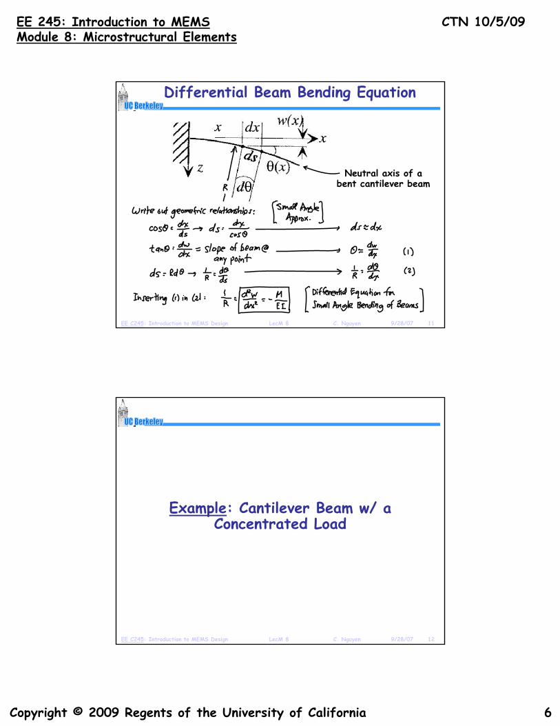
Folded-Beam Suspension
• Use of folded-beam suspension brings many benefitsStress relief: folding truss is free to move in y-direction, so beams can expand and contract more readily to relieve stressHigh y-axis to x-axis stiffness ratio Folding Truss
x
y
z
EE C245: Introduction to MEMS Design LecM 8 C. Nguyen 9/28/07 22
Comb-Driven Folded Beam Actuator

EE 245: Introduction to MEMSModule 8: Microstructural Elements
CTN 10/5/09
12Copyright © 2009 Regents of the University of California
Beam End Conditions
EE C245: Introduction to MEMS Design LecM 8 C. Nguyen 9/28/07 23
[From Reddy, Finite Element Method]
Common Loading & Boundary Conditions
• Displacement equations derived for various beams with concentrated load F or distributed load f
• Gary Fedder Ph.D. Thesis, EECS, UC Berkeley, 1994
EE C245: Introduction to MEMS Design LecM 8 C. Nguyen 9/28/07 24

EE 245: Introduction to MEMSModule 8: Microstructural Elements
CTN 10/5/09
13Copyright © 2009 Regents of the University of California
Series Combinations of Springs
• For springs in series w/ one loadDeflections addSpring constants combine like “resistors in parallel”
x
y
z
EE C245: Introduction to MEMS Design LecM 8 C. Nguyen 9/28/07 25
Compliances effectively add:
1/k = 1/kc + 1/kc
Y(L) = F/k = 2 y(Lc) = 2 (F/kc) = F(1/kc + 1/kc)
k = kc||kc→
Parallel Combinations of Springs
• For springs in parallel w/ one loadLoad is shared between the two springsSpring constant is the sum of the individual spring constants
x
y
z
EE C245: Introduction to MEMS Design LecM 8 C. Nguyen 9/28/07 26
Y(L) = F/k = Fa/ka = Fb/kb = (F/2) (1/ka)
k = 2 ka

EE 245: Introduction to MEMSModule 8: Microstructural Elements
CTN 10/5/09
14Copyright © 2009 Regents of the University of California
Folded-Flexure Suspension Variants
• Below: just a subset of the different versions• All can be analyzed in a similar fashion
EE C245: Introduction to MEMS Design LecM 8 C. Nguyen 9/28/07 27
[From Michael Judy, Ph.D. Thesis, EECS, UC Berkeley, 1994]
Deflection of Folded Flexures
This equivalent to two cantilevers of
length Lc=L/2
Composite cantilever Composite cantilever free ends attach here
EE C245: Introduction to MEMS Design LecM 8 C. Nguyen 9/28/07 28
Half of F absorbed in other half
(symmetrical)4 sets of these pairs, each of
which gets ¼ of the total force F

EE 245: Introduction to MEMSModule 8: Microstructural Elements
CTN 10/5/09
15Copyright © 2009 Regents of the University of California
Constituent Cantilever Spring Constant
• From our previous analysis:
( )yLEI
yFLyy
EILFyx c
z
c
cz
cc −=⎟⎟⎠
⎞⎜⎜⎝
⎛−= 3
631
2)(
22
zcz ⎠⎝
33
)( c
z
c
cc L
EILx
Fk ==
• From which the spring constant is:
• Inserting L = L/2
EE C245: Introduction to MEMS Design LecM 8 C. Nguyen 9/28/07 29
Inserting Lc = L/2
3324
)2/(3
LEI
LEI
k zzc ==
Overall Spring Constant
• Four pairs of clamped-guided beamsIn each pair, beams bend in series(Assume trusses are inflexible)
• Force is shared by each pair → Fpair = F/4
Rigid Truss
Force is shared by each pair → Fpair F/4
Leg
L
EE C245: Introduction to MEMS Design LecM 8 C. Nguyen 9/28/07 30
Fpair
EE 245: Introduction to MEMSModule 8: Microstructural Elements
CTN 10/5/09
16Copyright © 2009 Regents of the University of California
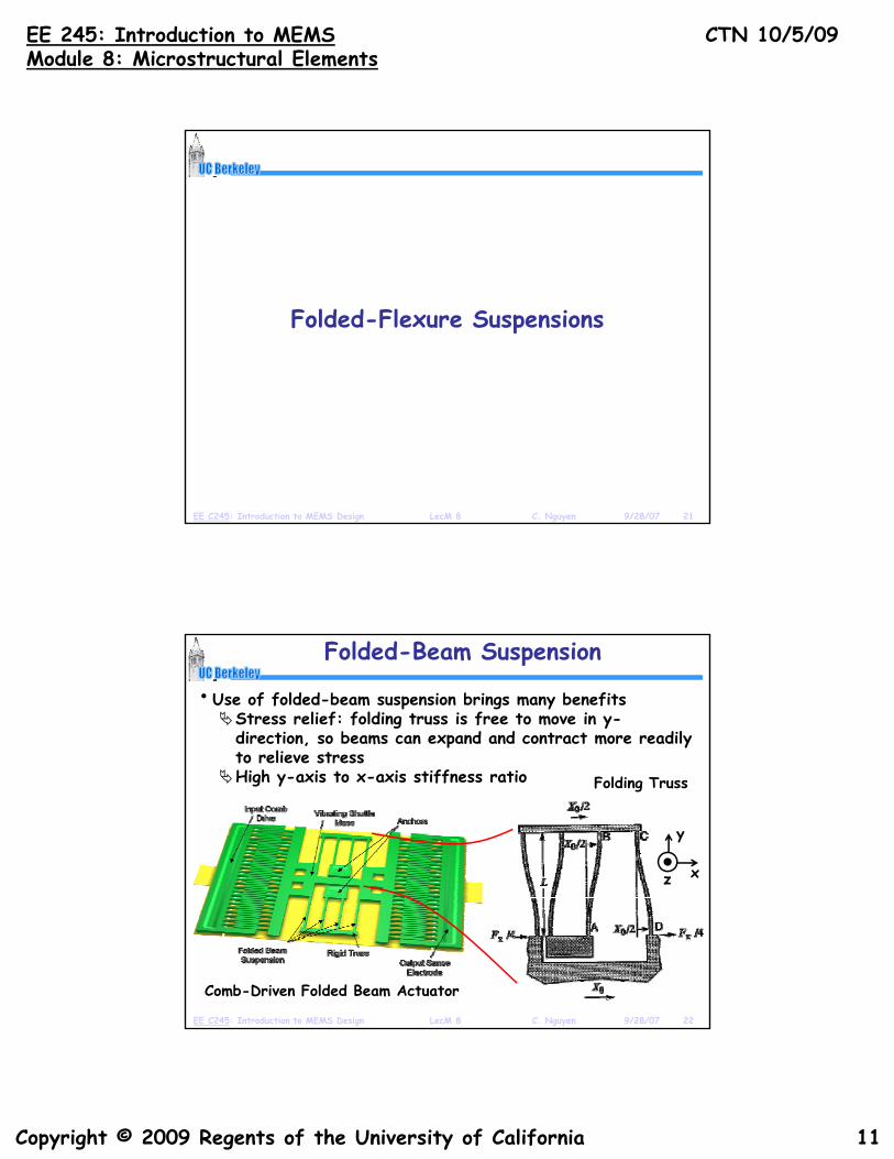
Folded-Beam Stiffness Ratios
• In the x-direction:
• In the z direction:
Folded-beam suspension
324
LEI
k zx =
In the z-direction:Same flexure and boundary conditions
• In the y-direction:Shuttle
324
LEIk x
z =
EWh8
EE C245: Introduction to MEMS Design LecM 8 C. Nguyen 9/28/07 31
• Thus: Anchor
Folding truss
LEWhk y
8=
2
4 ⎟⎠⎞
⎜⎝⎛=WL
kk
x
yMuch
stiffer in y-direction!
[See Senturia, §9.2]
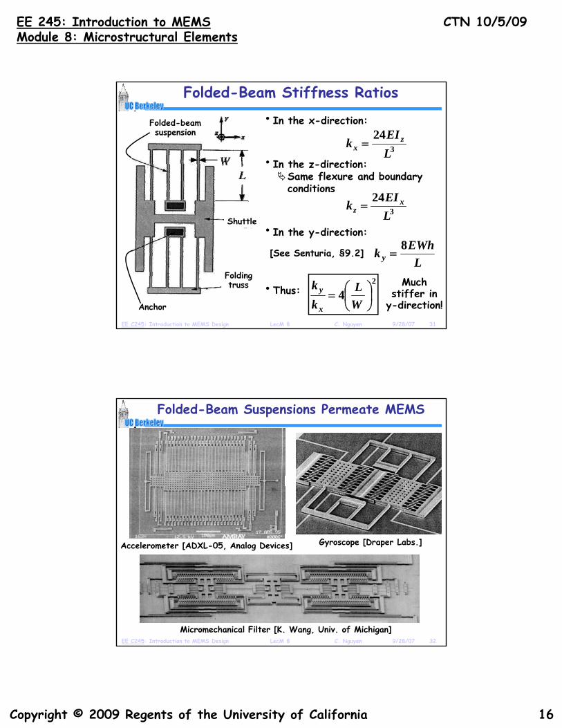
Folded-Beam Suspensions Permeate MEMS
Gyroscope [Draper Labs.]Accelerometer [ADXL-05, Analog Devices]
EE C245: Introduction to MEMS Design LecM 8 C. Nguyen 9/28/07 32
Micromechanical Filter [K. Wang, Univ. of Michigan]

EE 245: Introduction to MEMSModule 8: Microstructural Elements
CTN 10/5/09
17Copyright © 2009 Regents of the University of California
Folded-Beam Suspensions Permeate MEMS
• Below: Micro-Oven Controlled Folded-Beam Resonator
EE C245: Introduction to MEMS Design LecM 8 C. Nguyen 9/28/07 33
Stressed Folded-Flexures
EE C245: Introduction to MEMS Design LecM 8 C. Nguyen 9/28/07 34

EE 245: Introduction to MEMSModule 8: Microstructural Elements
CTN 10/5/09
18Copyright © 2009 Regents of the University of California
Clamped-Guided Beam Under Axial Load
• Important case for MEMS suspensions, since the thin films comprising them are often under residual stress
• Consider small deflection case: y(x) « Lxz
Governing differential equation: (Euler Beam Equation)
L
W
x
y
EE C245: Introduction to MEMS Design LecM 8 C. Nguyen 9/28/07 35
Governing differential equation: (Euler Beam Equation)
Unit impulse @ x=LAxial Load
The Euler Beam Equation
RAxial Stress
• Axial stresses produce no net horizontal force; but as soon as the beam is bent, there is a net downward force
For equilibrium, must postulate some kind of upward load on the beam to counteract the axial stress derived force
EE C245: Introduction to MEMS Design LecM 8 C. Nguyen 9/28/07 36
on the beam to counteract the axial stress-derived forceFor ease of analysis, assume the beam is bent to angle π

EE 245: Introduction to MEMSModule 8: Microstructural Elements
CTN 10/5/09
19Copyright © 2009 Regents of the University of California
The Euler Beam Equation
Note: Use of the full bend angle of π to
establish conditions for load balance; but this returns us to case of
small displacements and small angles
EE C245: Introduction to MEMS Design LecM 8 C. Nguyen 9/28/07 37
Clamped-Guided Beam Under Axial Load
• Important case for MEMS suspensions, since the thin films comprising them are often under residual stress
• Consider small deflection case: y(x) « Lxz
Governing differential equation: (Euler Beam Equation)
L
W
x
y
EE C245: Introduction to MEMS Design LecM 8 C. Nguyen 9/28/07 38
Governing differential equation: (Euler Beam Equation)
Unit impulse @ x=LAxial Load

EE 245: Introduction to MEMSModule 8: Microstructural Elements
CTN 10/5/09
20Copyright © 2009 Regents of the University of California
Solving the ODE
• Can solve the ODE using standard methodsSenturia, pp. 232-235: solves ODE for case of point load on a clamped-clamped beam (which defines B.C.’s)For solution to the clamped-guided case: see S. p gTimoshenko, Strength of Materials II: Advanced Theory and Problems, McGraw-Hill, New York, 3rd Ed., 1955
• Result from Timoshenko:
EE C245: Introduction to MEMS Design LecM 8 C. Nguyen 9/28/07 39
Design Implications
• Straight flexuresLarge tensile S means flexure behaves like a tensioned wire (for which k-1 = L/S)Large compressive S can lead to buckling (k-1 → ∞)g p g ( )
• Folded flexuresResidual stress only partially releasedLength from truss to shuttle’s centerline differs
EE C245: Introduction to MEMS Design LecM 8 C. Nguyen 9/28/07 40
centerline differs by Ls for inner and outer legs

EE 245: Introduction to MEMSModule 8: Microstructural Elements
CTN 10/5/09
21Copyright © 2009 Regents of the University of California
Effect on Spring Constant
• Residual compression on outer legs with same magnitude of tension on inner legs:
⎟⎠⎞
⎜⎝⎛±=
LLs
rb εεBeam Strain: ; Stress Force: WhLLES s
r ⎟⎠⎞
⎜⎝⎛±= ε
• Spring constant becomes:⎠⎝ Lrb Lr
⎠⎝
EE C245: Introduction to MEMS Design LecM 8 C. Nguyen 9/28/07 41
• Remedies:Reduce the shoulder width Ls to minimize stress in legsCompliance in the truss lowers the axial compression and tension and reduces its effect on the spring constant