Embed Size (px)
Citation preview
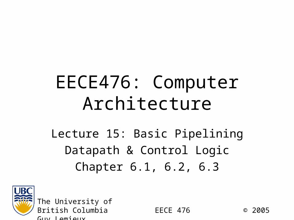
EECE476: Computer Architecture
Lecture 15: Basic Pipelining
Datapath & Control Logic
Chapter 6.1, 6.2, 6.3
The University ofBritish Columbia EECE 476 © 2005 Guy Lemieux

2
Announcements
• Tutorial this week– Study problems given in Lecture 14
• Midterm 1: Oct 20 in tutorial– 50 minutes, not open book, calculator OK– Based on your assignments + lecture material (up to
end of last week)– No Verilog, Altera tools on midterm– Try Lecture 14 study problems– Try more study problems online this week

3
1-Cycle CPU Datapath

4
1-Cycle CPU Datapath Stages

5
1-Cycle CPU Datapath Stages

6
1-Cycle CPU Datapath Stages

7
Dataflow of “lw $1, 100($0)”

8
Dataflow of “lw $1, 100($0)”
Send PC, fetch“LW” instruction

9
Dataflow of “lw $1, 100($0)”
Read registers rs and rt($1 and $0, $1 unused)
10
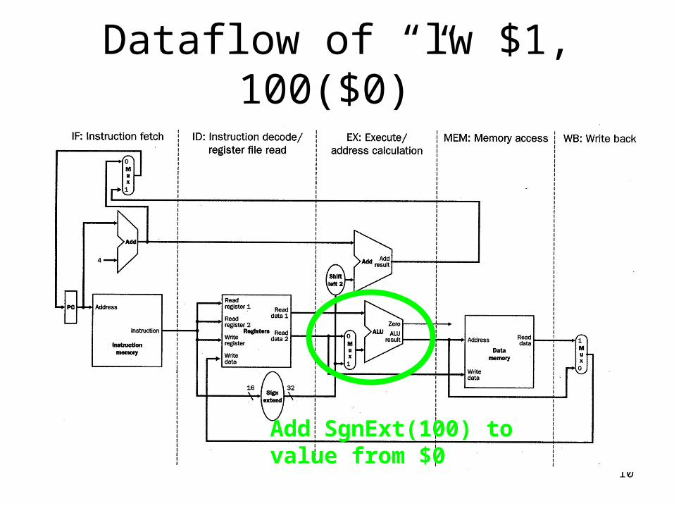
Dataflow of “lw $1, 100($0)”
Add SgnExt(100) tovalue from $0
11
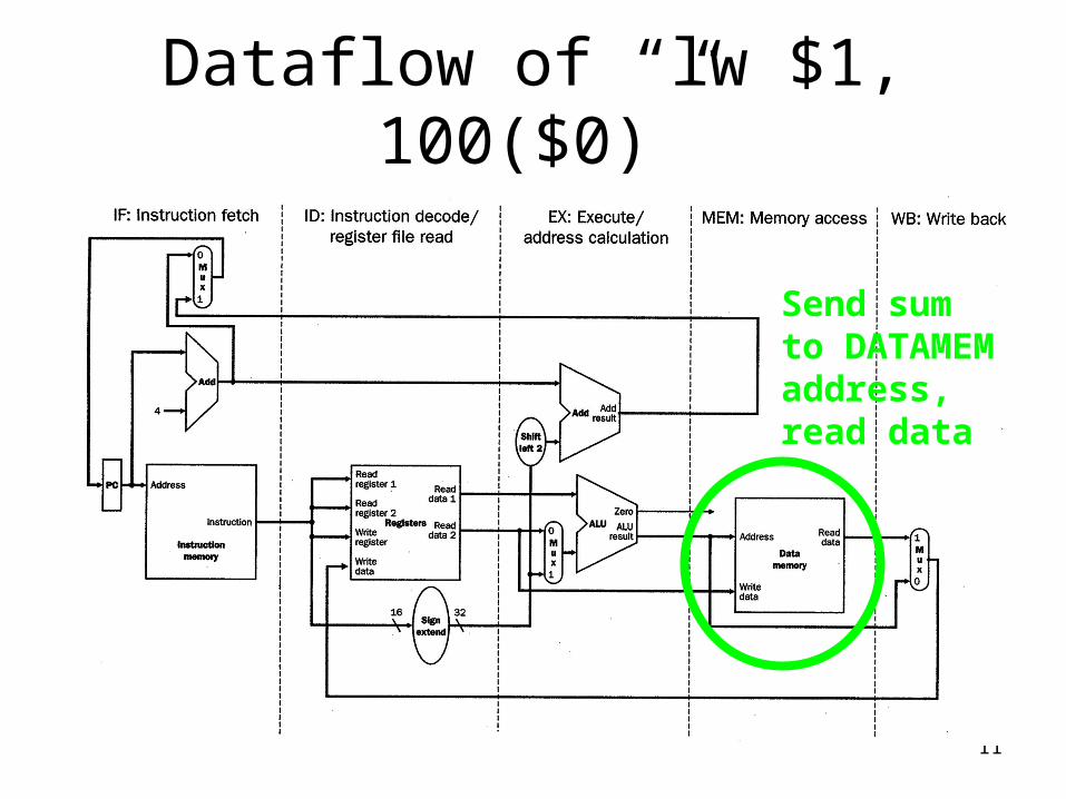
Dataflow of “lw $1, 100($0)”
Send sumto DATAMEMaddress,read data

12
Dataflow of “lw $1, 100($0)”
Writedatato rt($1)

13
Performance of “lw $1, 100($0)”
• 1-cycle CPU:– I: Instruction fetch +– D: Instruction Decode / Registerfile Read +– X: Execute +– M: DataMemory Access +– W: Write Back Result
• Cycle time = time for I+D+X+M+W– Eg: 2ns + 1ns + 2ns + 2ns + 1ns = 8ns– “lw” takes 8ns
• Remember: all instructions must take 8ns
14
Performance of “lw $1, 100($0)”
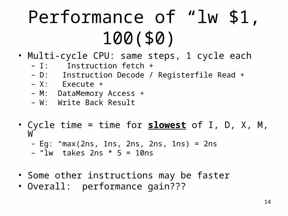
• Multi-cycle CPU: same steps, 1 cycle each– I: Instruction fetch +– D: Instruction Decode / Registerfile Read +– X: Execute +– M: DataMemory Access +– W: Write Back Result
• Cycle time = time for slowest of I, D, X, M, W– Eg: max(2ns, 1ns, 2ns, 2ns, 1ns) = 2ns– “lw” takes 2ns * 5 = 10ns
• Some other instructions may be faster• Overall: performance gain???

15
Another Way: Pipelining• Recall: data flows left-to-right

16
Pipeline Registers• Add registers between stages of execution

17
Pipeline Registers• Add registers between stages of execution
Send PC, fetch“LW” instruction
Pipeline Register Stores “lw” Instruction

18
Pipeline Registers• Add registers between stages of execution
Pipeline Register Stores rs, rt, SgnExt(100)

19
Pipeline Registers• Add registers between stages of execution
Pipeline Register Stores ALUout

20
Pipeline Registers• Add registers between stages of execution
Pipeline Register Stores DATAout

21
Pipeline Registers• Add registers between stages of execution
Register File Stores DATAout to $1 RegisterFile acts like final pipeline register

22
Pipelining: What’s the point?
• Break instruction into small steps
• “LW” takes 5 cycles * 2ns = 10ns
• First step takes only 2ns– After I step, INSTRMEM is idle– After D step, INSTRMEM + REGFILE are idle– After X step, ALU is idle– After M step, DATAMEM is idle– After W step, we’re done… start new instruction

23
Pipelining: What’s the point?Instruction Latency is Unchanged!
• Many steps, many stages are idle!• Start the next instruction early:
– LW $1, 100(0): I D X M W– LW $2, 200(0): I D X M W– LW $3, 200(0): I D X M W
• Instruction Latency– 1 instruction takes 5 * 2ns = 10ns– Instruction Latency is 10ns
• Instruction Throughput ?– Need multiple instructions…
Increasing Time

24
Pipelining: What’s the point?Instruction Throughput Improves 5x!!
• Many steps, many stages are idle!• Start the next instruction early:
– LW $1, 100(0): I D X M W– LW $2, 200(0): I D X M W– LW $3, 200(0): I D X M W
• Multiple Instructions– 3 instructions take 5 + 1 + 1 cycles
• Average: 7*2ns/3 = 14/3 = 4.6ns each– 5 instructions take 5 + 1 + 1 + 1 + 1 cycles
• Average: 9*2ns/5 = 18/5 = 3.6ns each
• Instruction Throughput– N instructions take 5 + (N-1) cycles
• Average: (5+N-1)*2ns/(N) = (N+4)/N * 2ns– Instruction Throughput: Limit NInfinity, or 2ns per instruction
Increasing Time

CONTROL LOGIC

26
Basic Pipeline
27
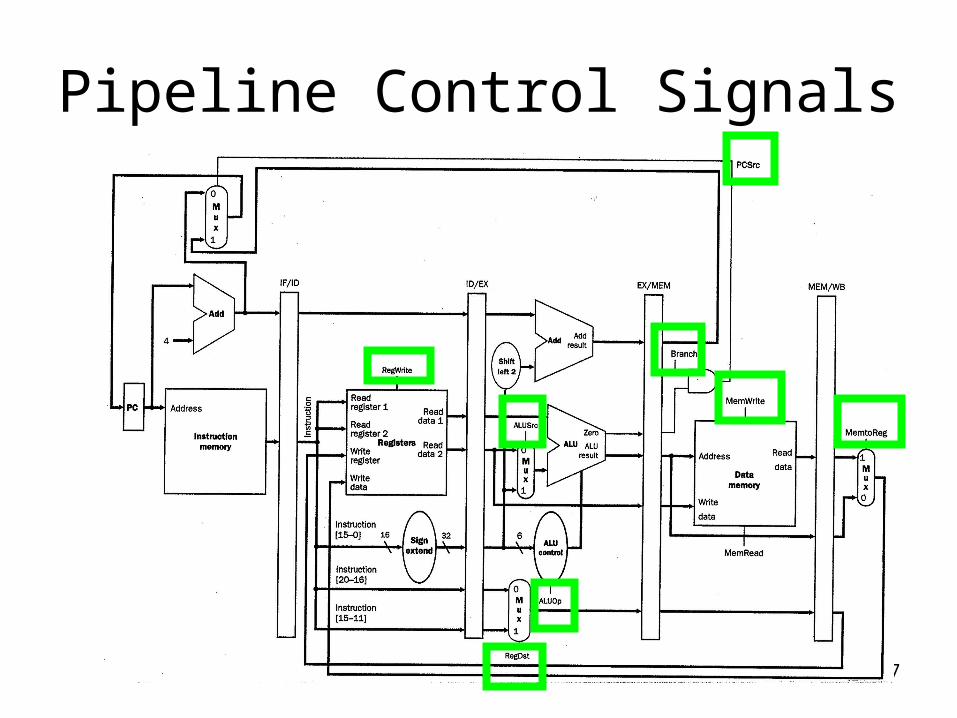
Pipeline Control Signals

28
Pipelined Control
• Control signals appear in each pipeline stage
• Previous Control Strategies– Combinational Control (single-cycle CPU)
• Cannot apply here, many instructions in pipeline
– Sequential Control (FSM for multi-cycle CPU)• Cannot apply here, many instructions in pipeline
• New strategy– Start with combinational control– Pipeline it !
• Make proper control signals flow alongside with each instruction
29
Pipelined Control
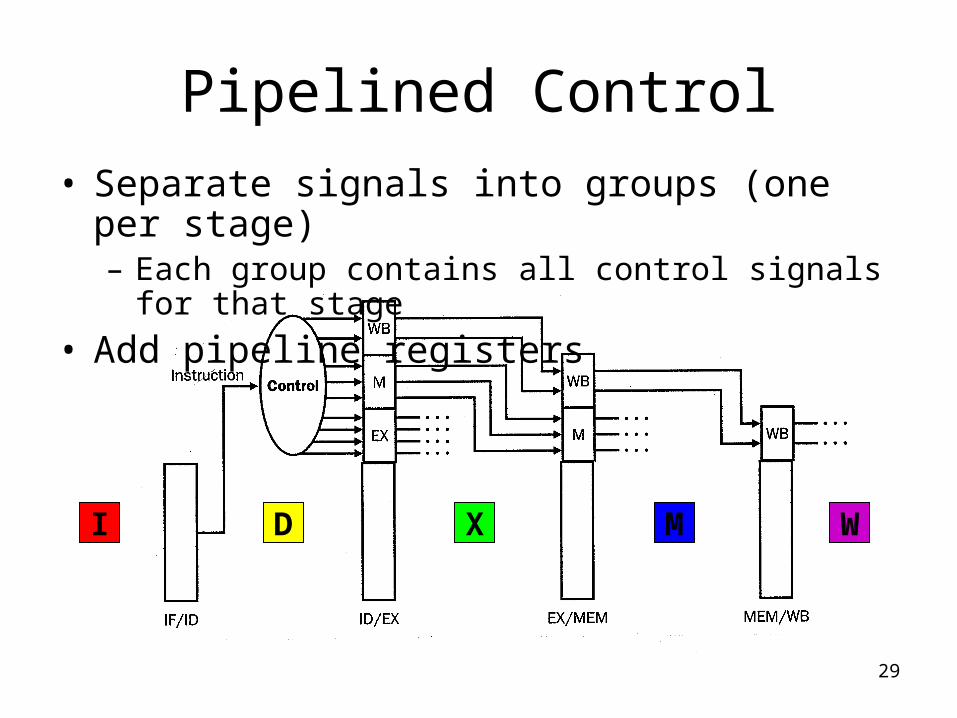
• Separate signals into groups (one per stage)– Each group contains all control signals for that stage
• Add pipeline registers
WMXDI

30
Pipelined Control
WMX