Embed Size (px)
DESCRIPTION
EE 3RD SEMESTER COURSE PLANS
Citation preview


Prerequisite: Basic Electronics (ECE 101/102) Program Objectives:
At the end of the program the students must be able to:
1. Draw the characteristics and analyze the operation of semiconductor
devices.
2. Develop small signal models of transistors for linear applications. 3. Understand the principle of operation of field-effect transistors and their
applications.
4. Design and implement voltage regulator and passive filter circuits.
5. Designing class A, B, AB, push-pull amplifiers Program Outcomes:
• An ability to apply knowledge of Mathematics, Science & Engineering.
• An ability to design and conduct experiments as well as to analyze and
interpret data.
• An ability to function on multidisciplinary teams.
• An ability to identify, formulate and solve engineering problems.
• The broad education necessary to understand the impact of engineering
solutions in a global, economic, environmental and societal context.
• A recognition of the need for and an ability to engage in lifelong learning.
• An ability to use the techniques, skills and modern engineering tools
necessary for engineering practice.
Page 2 of 5 MIT/GEN/F-05/ELE/R0
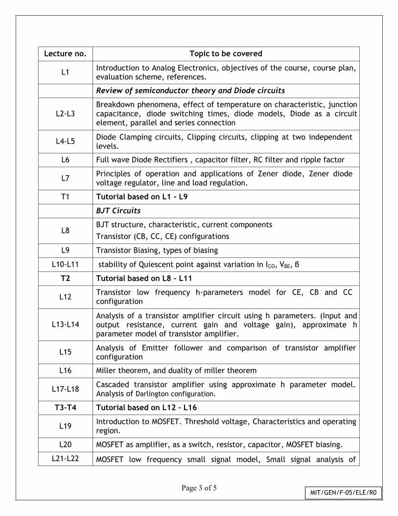
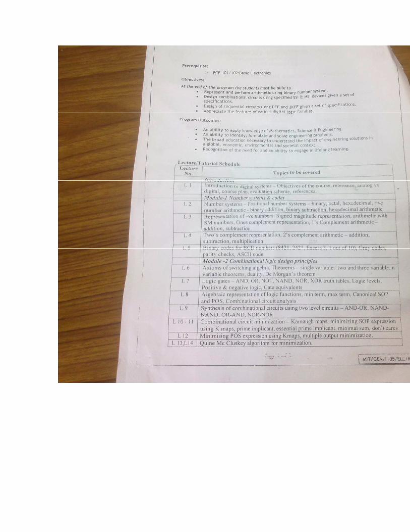
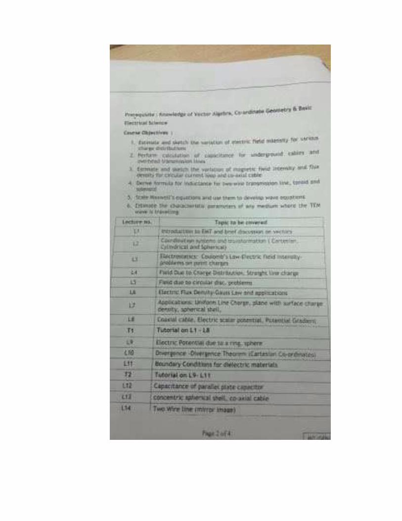
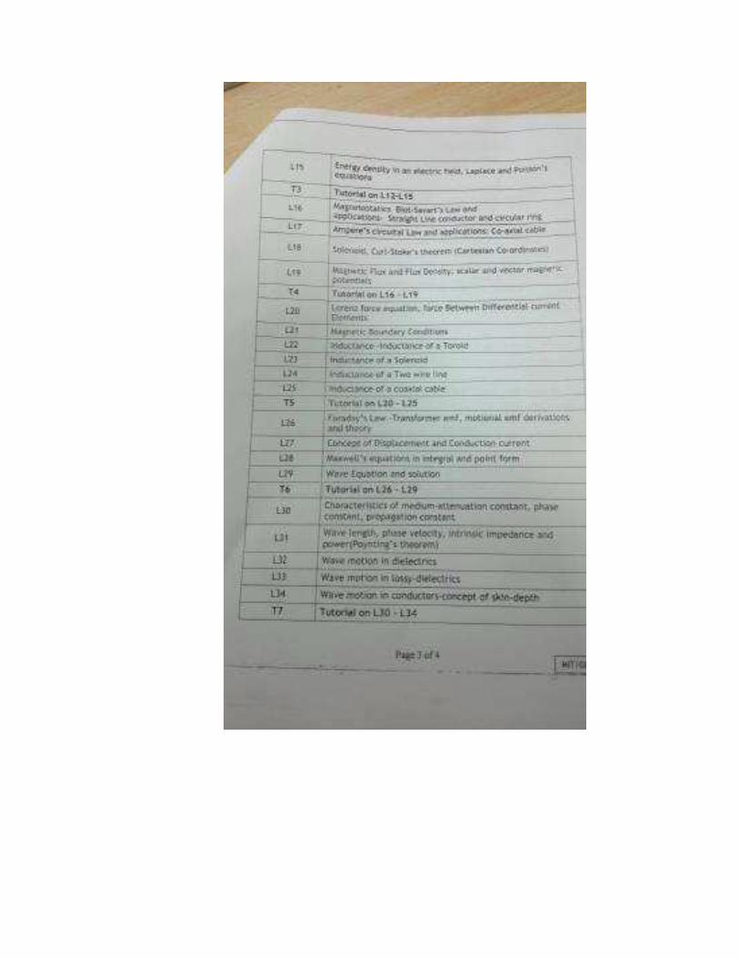
Lecture no. Topic to be covered
L1 Introduction to Analog Electronics, objectives of the course, course plan, evaluation scheme, references.
Review of semiconductor theory and Diode circuits
L2-L3 Breakdown phenomena, effect of temperature on characteristic, junction capacitance, diode switching times, diode models, Diode as a circuit element, parallel and series connection
L4-L5 Diode Clamping circuits, Clipping circuits, clipping at two independent
levels.
L6 Full wave Diode Rectifiers , capacitor filter, RC filter and ripple factor
L7 Principles of operation and applications of Zener diode, Zener diode voltage regulator, line and load regulation.
T1 Tutorial based on L1 – L9
BJT Circuits
L8 BJT structure, characteristic, current components
Transistor (CB, CC, CE) configurations
L9 Transistor Biasing, types of biasing
L10-L11 stability of Quiescent point against variation in ICO, VBE, β
T2 Tutorial based on L8 – L11
L12 Transistor low frequency h-parameters model for CE, CB and CC configuration
L13-L14 Analysis of a transistor amplifier circuit using h parameters. (Input and output resistance, current gain and voltage gain), approximate h parameter model of transistor amplifier.
L15 Analysis of Emitter follower and comparison of transistor amplifier
configuration
L16 Miller theorem, and duality of miller theorem
L17-L18 Cascaded transistor amplifier using approximate h parameter model. Analysis of Darlington configuration.
T3-T4 Tutorial based on L12 – L16
L19 Introduction to MOSFET. Threshold voltage, Characteristics and operating region.
L20 MOSFET as amplifier, as a switch, resistor, capacitor, MOSFET biasing.
L21-L22 MOSFET low frequency small signal model, Small signal analysis of
Page 3 of 5 MIT/GEN/F-05/ELE/R0

MOSFET amplifier and Single stage CS, CD, CG amplifier configurations.
L23-L24 Input and output resistance of CS,CD,CG configuration and input signal swing limits
T5-T6 Tutorial based on L17 – L21
L25-L26 Multistage amplifiers-cascaded amplifiers.
L27 Cascode amplifier connections.
L28 BJT, MOSFET Current source and Current mirror circuits and applications.
T7-T8 Tutorial based on L22 – L25
Frequency response of Amplifiers
L29-L30 Direct coupled, Capacitor coupled and RC coupled amplifier
L31 Frequency response of single stage and multi stage amplifiers
L32 bandwidth, gain-bandwidth product of cascaded amplifiers
L33-L34 Effect of coupling and emitter bypass capacitors on frequency response, Effect of stray and miller capacitances.
L35 High frequency model of Enhancement MOSFET. Safe operating area
T7-T8 Tutorial based on L28 – L32
Power amplifiers
L36-L37 Classification of large signal amplifiers, analysis and design with respect to efficiency
L38 Series fed and transformer coupled class A amplifiers, thermal run away
L39 Complementary and Quasi complimentary push pull amplifiers.
L40 Linearity and harmonic distortion in power amplifiers, Distortion analysis
T9 Tutorial based on L33 – L36
Power supplies
L41 Principle of voltage regulation, Series voltage regulator, Series voltage regulator with pre regulator and short circuit protection circuits
L42 Shunt voltage regulators
L43 Analysis and design of linear series voltage regulators using 78XX and 79XX series
L44 LM317, LM337, 723 ICs
T10 Tutorial based on L37 – L40
Page 4 of 5 MIT/GEN/F-05/ELE/R0
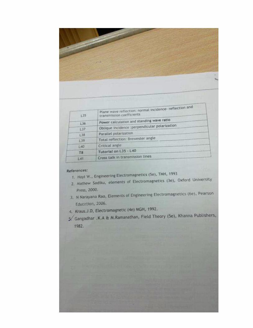
References:
1. A. S. Sedra & K. C. Smith, Microelec
University Press, 1999.
2. Theodore F Bogart, Electronic
3. Thomas L. Floyd, Electronic D
4. Millman and Halkias, Integra
Systems, TMH, 1992.
5. P.Boylestead and Nashalskey, 1998.
6. Richard C. Jaeger and Travis N
McGraw Hill, 2007
7. Richard R Spencer and MohammDesign, Pearson Education, 20
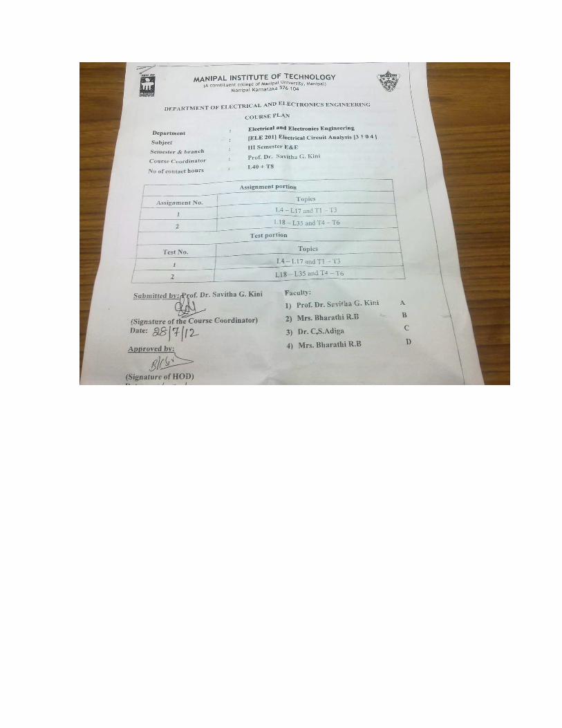
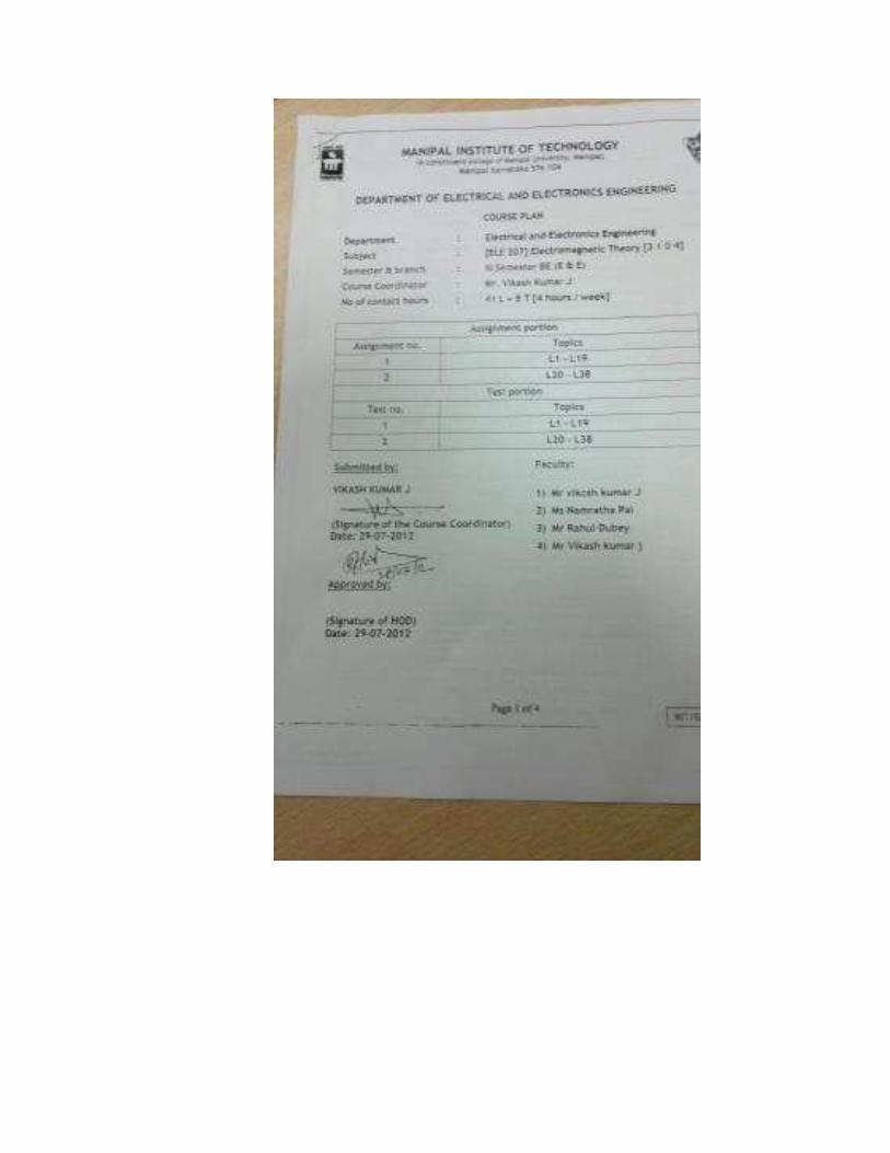
MANIPAL IN(A constitu
DEPARTMENT OF ELEC
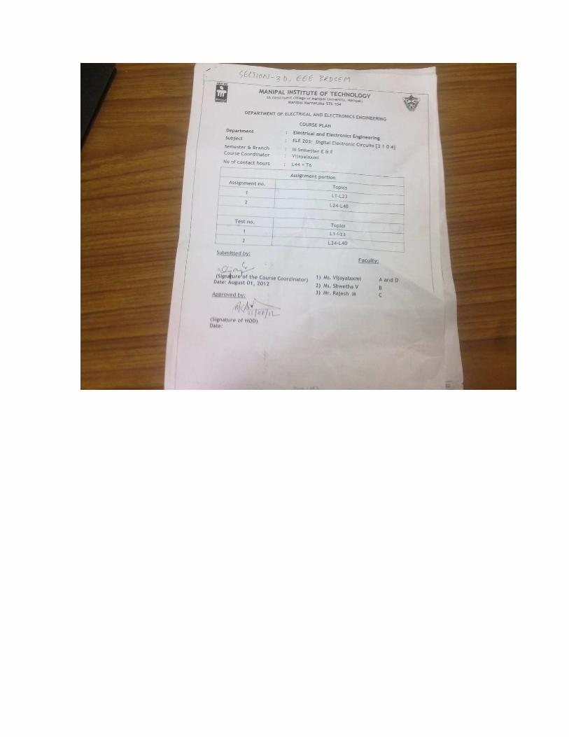
Subject : Semester & branch : Course Coordinator : No of contact hours :
Assignment no.
1
2
Test no.
1
2
croelectronics Circuits, 4th Edition, Oxford
ic Devices & Circuits 6th Edition, Prentice hall.
Devices, Pearson Education, 2002.
rated Electronics: Analog and Digital Circuits a
Electronic Devices and Circuit Theory, 6th Edit
N. Blalock, Microelectronic Circuit Design, 3rd Ed
ammed S. Ghousi, Introduction to Electronic Circ003.
NSTITUTE OF TECHNOLOGY uent college of Manipal University, Manipal) Manipal Karnataka 576 104
CTRICAL AND ELECTRONICS ENG
COURSE PLAN (ODD SEM: AUG-DEC 2012)
Electrical Machinery – I [ELE 205] [3 1 0 III Semester B.E (E & E) Prof. Mohan Kumar S 38 L + 12 T [4 hours / week]
Assignment portion
Topics
L01 – L15, T1 – T5
L16 – L31, T6 – T10
Test portion
Topics
L01 – L15, T1 – T5
L16 – L31, T6 – T10
and
ition, PHI,
Ed.
rcuit
NGINEERING
0 4]
Submitted by:
Prof. MOHAN KUMAR S. (Signature of the Course Coordinator) Date: July 30, 2012
Approved by:
(Signature of HOD) Date: July 30, 2012
Faculty 1) Divya Shetty (DS) A
2) James Antony Pinto (JP) B
3) G. Hari Babu (GHB) C
4) Rahul Dubey (RD) D
Page 1 of 4 MIT/GEN/F-05/R0
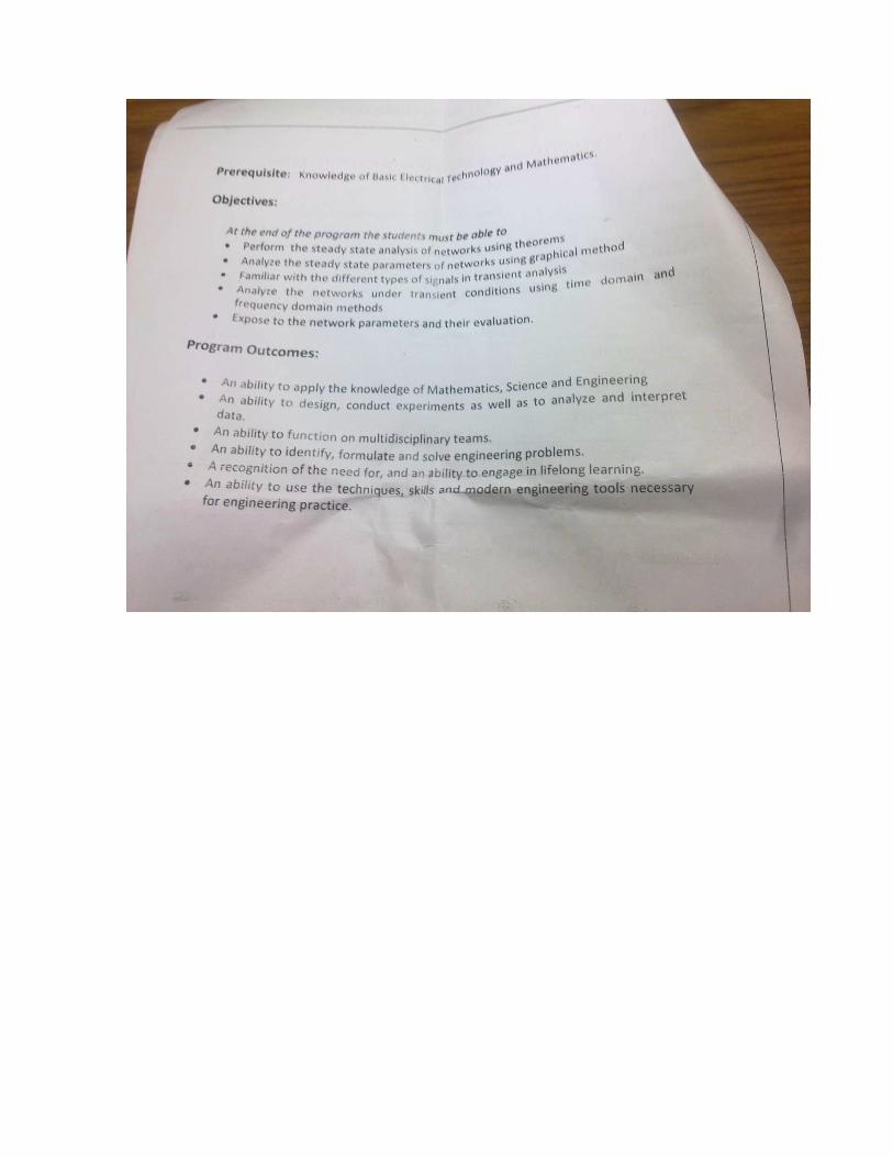
Pre-requisite: Basic Electrical Technolog
Course objectives At the end of the course, the stud
1. Explain the basic conce2. Understand and devel3. Perform experiments r4. Analyze the performa
circuit models
Program outcome:
The course shall demonstrate
1. an ability to apply kno2. an ability to identify, f3. a recognition of the nee4. an ability to use the tec
engineering practice. Evaluation Scheme:
Internal Assessment: 50 Marks
Two tests - 20 Ma2 nos. of Assignm
End Semester Examination: 50
Questions shall coSix questions are sStudents must ans
ogy (ELE 101 / 102)
udents must be able to: cepts of rotating electrical machines lop the constructional aspects of ac & dc machinrelated to ac & dc machinery ance characteristics of ac & dc machinery from
e the students shall attain the following outcomes
owledge of mathematics, science and engineeringformulate and solve engineering problems eed for and an ability to engage in life-long learnechniques, skills and modern engineering tools ne
arks each ments - 5 Marks each
Marks
over the entire syllabus set, each of 10 marks swer any five questions
Page 2 of 4
nery
m the equivalent
s:
ng
ning necessary for
MIT/GEN/F-05/R0
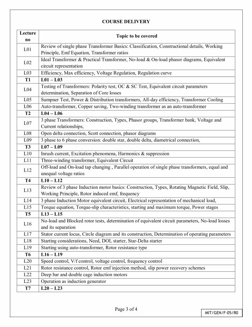
COURSE DELIVERY
Lecture no
Topic to be covered
L01 Review of single phase Transformer Basics: Classification, Constructional details, Working Principle, Emf Equation, Transformer ratios
L02 Ideal Transformer & Practical Transformer, No-load & On-load phasor diagrams, Equivalent circuit representation
L03 Efficiency, Max efficiency, Voltage Regulation, Regulation curve T1 L01 – L03
L04 Testing of Transformers: Polarity test, OC & SC Test, Equivalent circuit parameters determination, Separation of Core losses
L05 Sumpner Test, Power & Distribution transformers, All-day efficiency, Transformer Cooling L06 Auto-transformer, Copper saving, Two-winding transformer as an auto-transformer T2 L04 – L06
L07 3 phase Transformers: Construction, Types, Phasor groups, Transformer bank, Voltage and Current relationships,
L08 Open delta connection, Scott connection, phasor diagrams L09 3 phase to 6 phase conversion: double star, double delta, diametrical connection, T3 L07 – L09 L10 Inrush current, Excitation phenomena, Harmonics & suppression L11 Three-winding transformer, Equivalent Circuit
L12 Off-load and On-load tap changing , Parallel operation of single phase transformers, equal and unequal voltage ratios
T4 L10 – L12
L13 Review of 3 phase Induction motor basics: Construction, Types, Rotating Magnetic Field, Slip, Working Principle, Rotor induced emf, frequency
L14 3 phase Induction Motor equivalent circuit, Electrical representation of mechanical load, L15 Torque equation, Torque-slip characteristics, starting and maximum torque, Power stages T5 L13 – L15
L16 No-load and Blocked rotor tests, determination of equivalent circuit parameters, No-load losses and its separation
L17 Stator current locus, Circle diagram and its construction, Determination of operating parameters L18 Starting considerations, Need, DOL starter, Star-Delta starter L19 Starting using auto-transformer, Rotor resistance type T6 L16 – L19 L20 Speed control, V/f control, voltage control, frequency control L21 Rotor resistance control, Rotor emf injection method, slip power recovery schemes L22 Deep bar and double cage induction motors L23 Operation as induction generator T7 L20 – L23
Page 3 of 4 MIT/GEN/F-05/R0
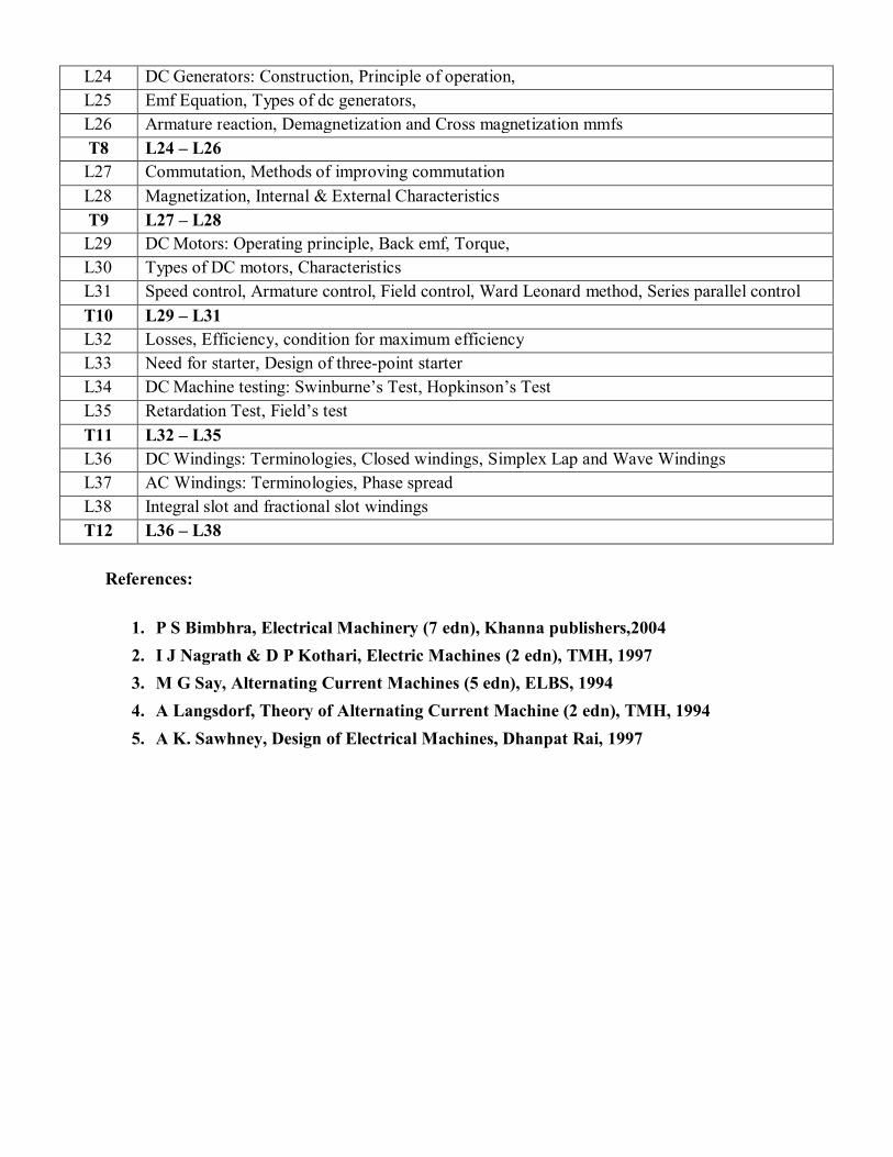
L24 DC Generators: Construction, Principle of operation, L25 Emf Equation, Types of dc generators, L26 Armature reaction, Demagnetization and Cross magnetization mmfs T8 L24 – L26 L27 Commutation, Methods of improving commutation L28 Magnetization, Internal & External Characteristics T9 L27 – L28 L29 DC Motors: Operating principle, Back emf, Torque, L30 Types of DC motors, Characteristics L31 Speed control, Armature control, Field control, Ward Leonard method, Series parallel control T10 L29 – L31 L32 Losses, Efficiency, condition for maximum efficiency L33 Need for starter, Design of three-point starter L34 DC Machine testing: Swinburne’s Test, Hopkinson’s Test L35 Retardation Test, Field’s test T11 L32 – L35 L36 DC Windings: Terminologies, Closed windings, Simplex Lap and Wave Windings L37 AC Windings: Terminologies, Phase spread L38 Integral slot and fractional slot windings T12 L36 – L38
References:
1. P S Bimbhra, Electrical Machinery (7 edn), Khanna publishers,2004
2. I J Nagrath & D P Kothari, Electric Machines (2 edn), TMH, 1997
3. M G Say, Alternating Current Machines (5 edn), ELBS, 1994
4. A Langsdorf, Theory of Alternating Current Machine (2 edn), TMH, 1994
5. A K. Sawhney, Design of Electrical Machines, Dhanpat Rai, 1997
Page 4 of 4

Page 5 of 5

![OPJU EEE - III [MODIFIED]115.249.21.107/.../RESULT_EEE_3_REG_DEC_17.pdf · o p jindal university, raigarh (c.g.) result of b. tech. 3rd semester regular examination, december - 2017](https://img.pdfslide.net/doc/110x75/5f2375126cd89c57fa6d6902/opju-eee-iii-modified11524921107resulteee3regdec17pdf-o-p-jindal.jpg)