Embed Size (px)
Citation preview
Nuclear Engineering Program
Effect of 2011 Earthquake on
Japanese Nuclear Reactors
March 23, 2011
David Griesheimer
University of Pittsburgh
Nuclear Engineering Program
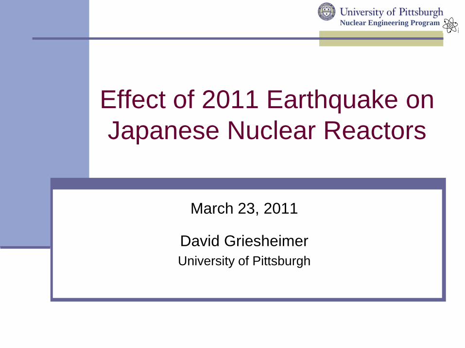
2011 Sendai Earthquake…
2
Associated Press
2011 Sendai earthquake and tsunami - Wikipedia, the free encyclopedia
http://en.wikipedia.org/wiki/2011_Sendai_earthquake_and_tsunami
Magnitude 9.0
4th Largest Recorded Earthquake
Energy release: 9.32 Ttons TNT
Moved Japan 8 feet
Shifted Earth 10 cm
(on axis)
2:46pm, March 11, 2011
Nuclear Engineering Program
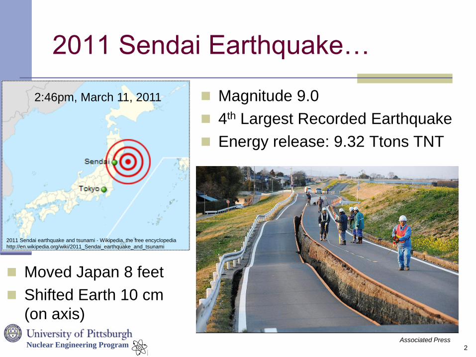
…and Tsunami
Inundated 420 miles of
eastern coast of Japan
Arrived 10-60 minutes
after earthquake
3
Observed heights:
11-24 feet
Affected entire pacific
ocean
NOAA
Kyodo/Associated Press
Nuclear Engineering Program
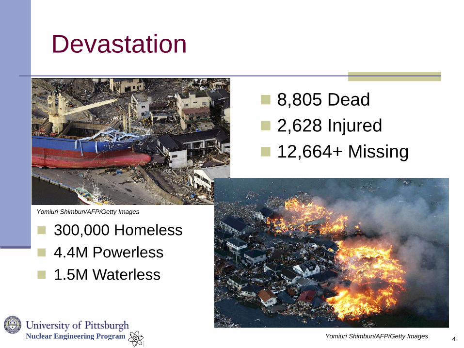
Devastation
8,805 Dead
2,628 Injured
12,664+ Missing
4 Yomiuri Shimbun/AFP/Getty Images
Yomiuri Shimbun/AFP/Getty Images
300,000 Homeless
4.4M Powerless
1.5M Waterless
Nuclear Engineering Program
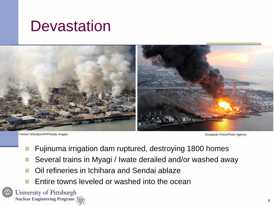
Devastation
5
Yomiuri Shimbun/AFP/Getty Images
Fujinuma irrigation dam ruptured, destroying 1800 homes
Several trains in Myagi / Iwate derailed and/or washed away
Oil refineries in Ichihara and Sendai ablaze
Entire towns leveled or washed into the ocean
European PressPhoto Agency
Nuclear Engineering Program
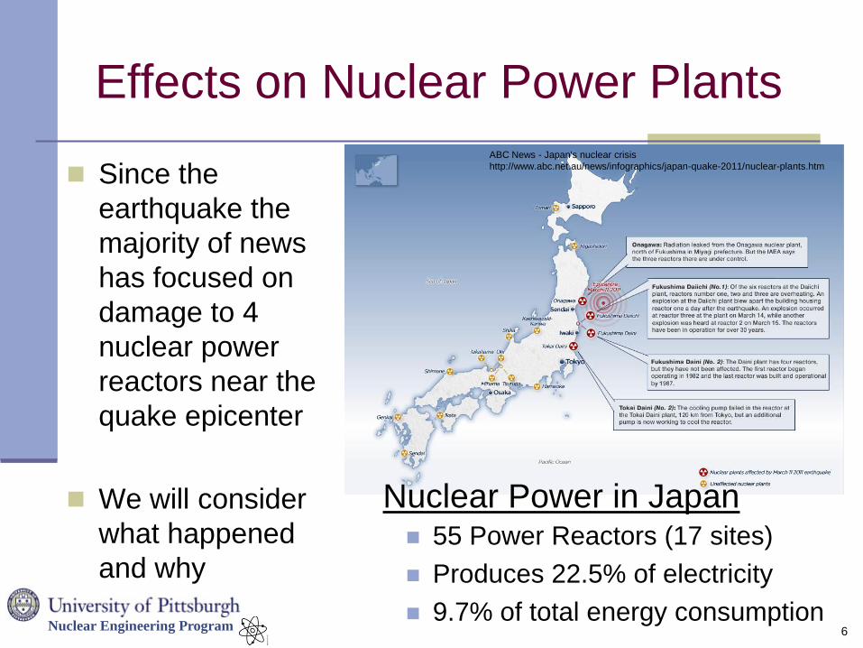
Effects on Nuclear Power Plants
6
Since the
earthquake the
majority of news
has focused on
damage to 4
nuclear power
reactors near the
quake epicenter
We will consider
what happened
and why 55 Power Reactors (17 sites)
Produces 22.5% of electricity
9.7% of total energy consumption
Nuclear Power in Japan
ABC News - Japan's nuclear crisis
http://www.abc.net.au/news/infographics/japan-quake-2011/nuclear-plants.htm
Nuclear Engineering Program
Presentation Objectives
Before we discuss the ongoing accident at
Fukushima Daiichi, it will be useful to
understand some basic concepts and
terminology about radiation and nuclear
reactors.
Emphasis on Boiling Water Reactor (BWR)
designs found at Fukushima Daiichi
7
Nuclear Engineering Program
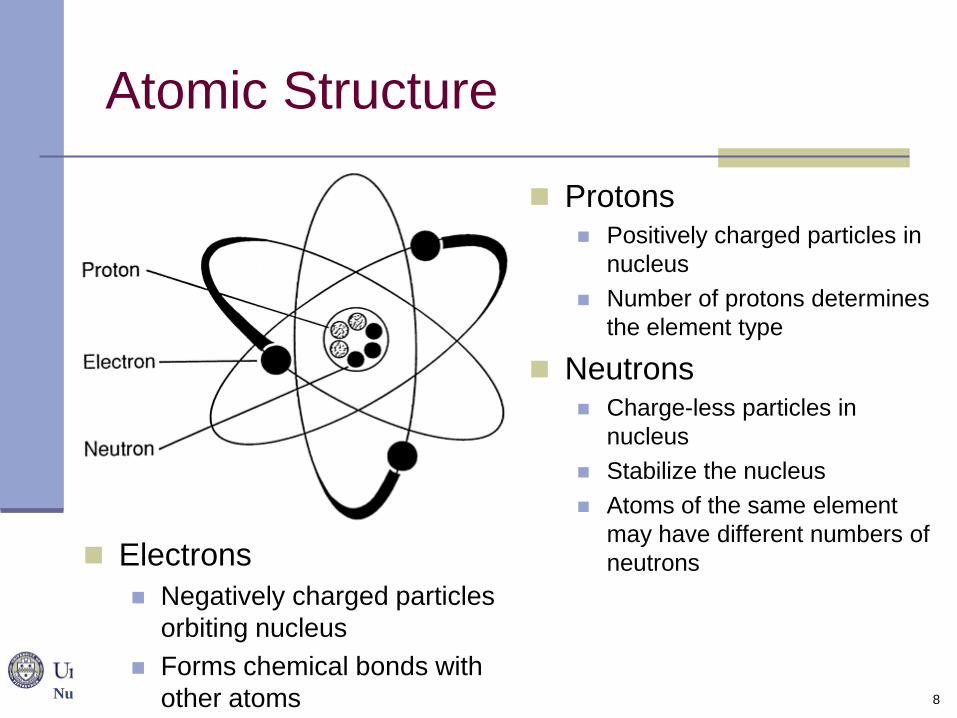
Atomic Structure
8
Protons Positively charged particles in
nucleus
Number of protons determines
the element type
Neutrons Charge-less particles in
nucleus
Stabilize the nucleus
Atoms of the same element
may have different numbers of
neutrons Electrons
Negatively charged particles
orbiting nucleus
Forms chemical bonds with
other atoms
Nuclear Engineering Program
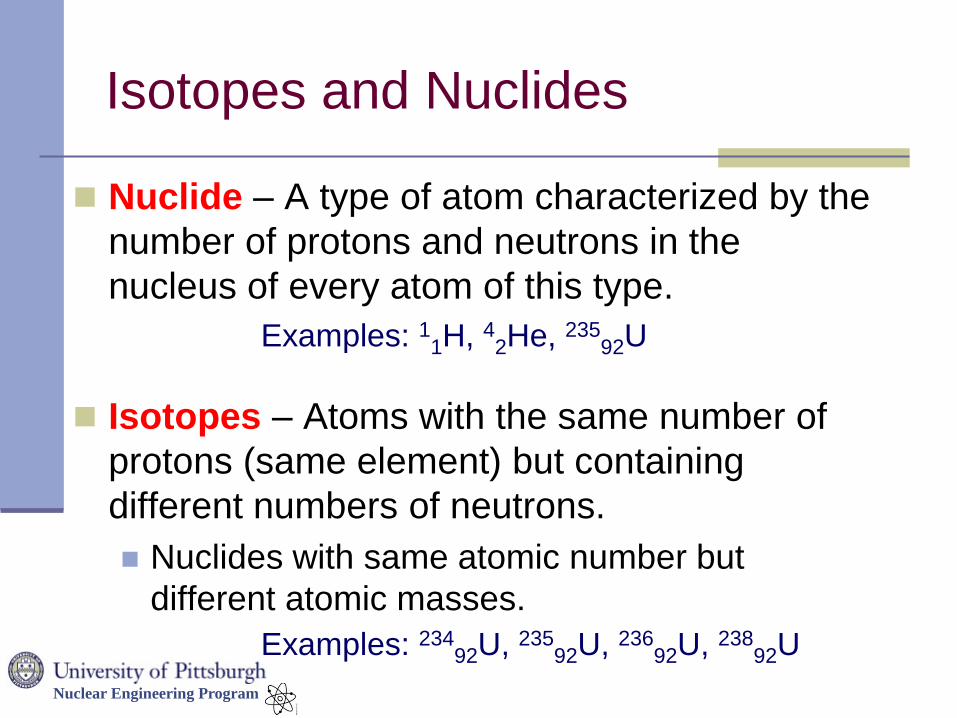
Isotopes and Nuclides
Nuclide – A type of atom characterized by the
number of protons and neutrons in the
nucleus of every atom of this type.
Isotopes – Atoms with the same number of
protons (same element) but containing
different numbers of neutrons.
Nuclides with same atomic number but
different atomic masses.
Examples: 11H, 42He, 23592U
Examples: 23492U, 235
92U, 23692U, 238
92U
Nuclear Engineering Program
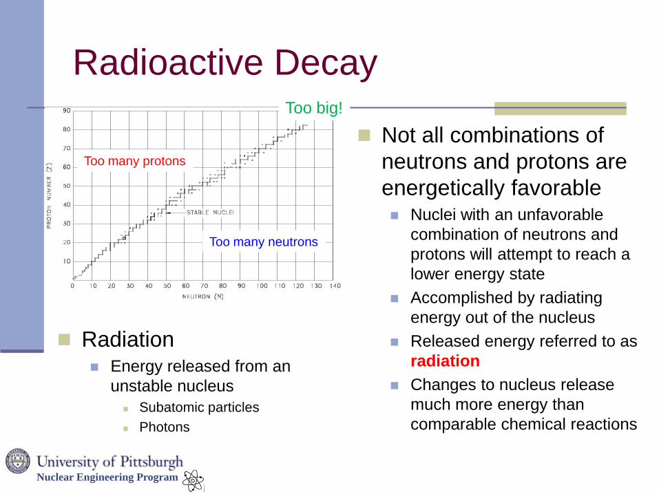
Radioactive Decay
Too many protons
Too many neutrons
Too big!
Not all combinations of
neutrons and protons are
energetically favorable Nuclei with an unfavorable
combination of neutrons and
protons will attempt to reach a
lower energy state
Accomplished by radiating
energy out of the nucleus
Released energy referred to as
radiation
Changes to nucleus release
much more energy than
comparable chemical reactions
Radiation Energy released from an
unstable nucleus
Subatomic particles
Photons
Nuclear Engineering Program
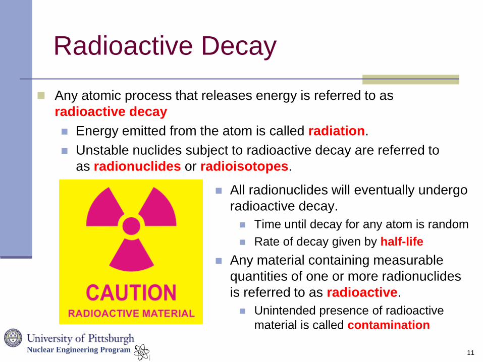
Radioactive Decay
Any atomic process that releases energy is referred to as
radioactive decay
Energy emitted from the atom is called radiation.
Unstable nuclides subject to radioactive decay are referred to
as radionuclides or radioisotopes.
11
All radionuclides will eventually undergo
radioactive decay.
Time until decay for any atom is random
Rate of decay given by half-life
Any material containing measurable
quantities of one or more radionuclides
is referred to as radioactive.
Unintended presence of radioactive
material is called contamination
Nuclear Engineering Program
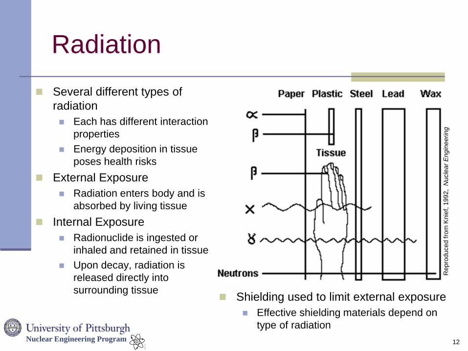
Radiation
Several different types of
radiation
Each has different interaction
properties
Energy deposition in tissue
poses health risks
External Exposure
Radiation enters body and is
absorbed by living tissue
Internal Exposure
Radionuclide is ingested or
inhaled and retained in tissue
Upon decay, radiation is
released directly into
surrounding tissue
12
Repro
duced fro
m K
nie
f, 1
992, N
ucle
ar
Engin
eeri
ng
Shielding used to limit external exposure
Effective shielding materials depend on
type of radiation
Nuclear Engineering Program
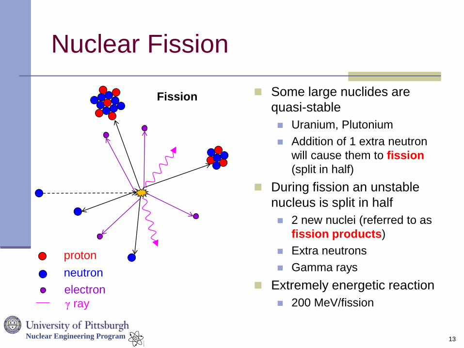
Nuclear Fission
Some large nuclides are
quasi-stable
Uranium, Plutonium
Addition of 1 extra neutron
will cause them to fission
(split in half)
During fission an unstable
nucleus is split in half
2 new nuclei (referred to as
fission products)
Extra neutrons
Gamma rays
Extremely energetic reaction
200 MeV/fission
13
Fission
proton
neutron
electron
γ ray
Nuclear Engineering Program
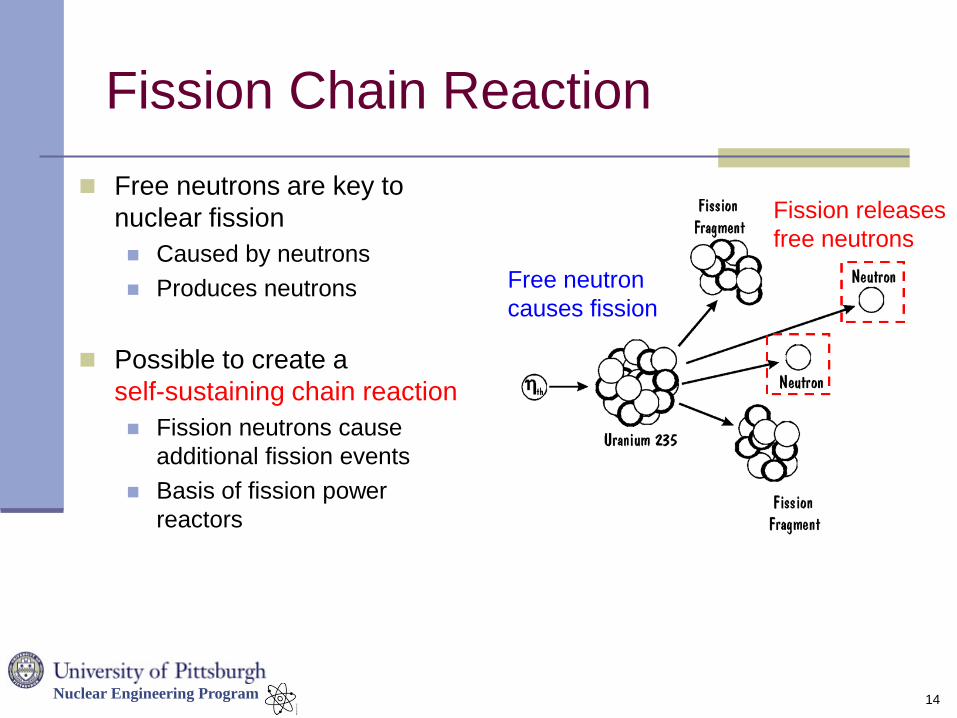
Fission Chain Reaction
Free neutrons are key to
nuclear fission
Caused by neutrons
Produces neutrons
Possible to create a
self-sustaining chain reaction
Fission neutrons cause
additional fission events
Basis of fission power
reactors
14
Free neutron
causes fission
Fission releases
free neutrons
Nuclear Engineering Program
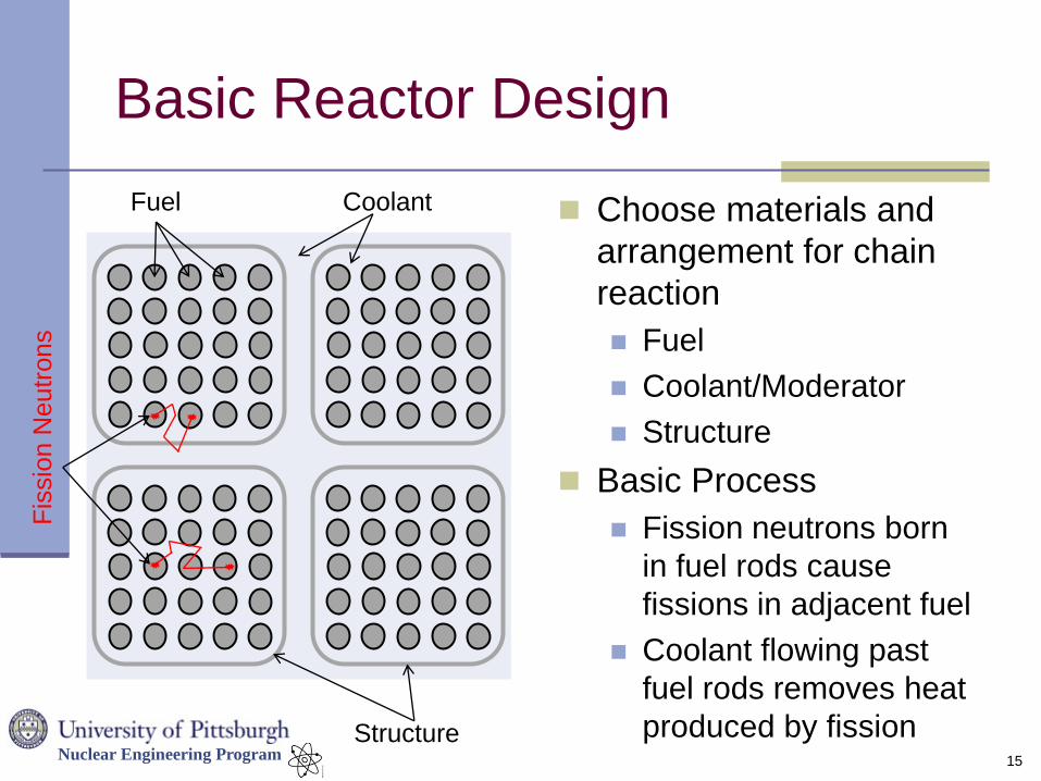
Basic Reactor Design
Choose materials and
arrangement for chain
reaction
Fuel
Coolant/Moderator
Structure
Basic Process
Fission neutrons born
in fuel rods cause
fissions in adjacent fuel
Coolant flowing past
fuel rods removes heat
produced by fission 15
Fuel Coolant
Structure
Fis
sio
n N
eutr
ons
Nuclear Engineering Program
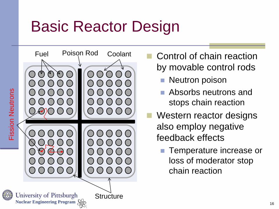
Basic Reactor Design
Control of chain reaction
by movable control rods
Neutron poison
Absorbs neutrons and
stops chain reaction
Western reactor designs
also employ negative
feedback effects
Temperature increase or
loss of moderator stop
chain reaction
16
Fuel Coolant
Structure
Fis
sio
n N
eutr
ons
Poison Rod
Nuclear Engineering Program
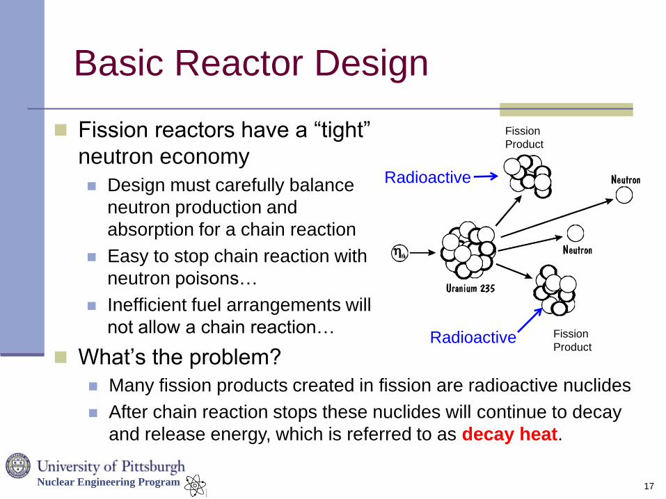
Basic Reactor Design
Fission reactors have a “tight”
neutron economy
Design must carefully balance
neutron production and
absorption for a chain reaction
Easy to stop chain reaction with
neutron poisons…
Inefficient fuel arrangements will
not allow a chain reaction…
What’s the problem?
17
Many fission products created in fission are radioactive nuclides
After chain reaction stops these nuclides will continue to decay
and release energy, which is referred to as decay heat.
Fission
Product
Fission
Product
Radioactive
Radioactive
Nuclear Engineering Program
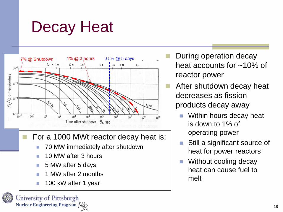
Decay Heat
During operation decay
heat accounts for ~10% of
reactor power
After shutdown decay heat
decreases as fission
products decay away
Within hours decay heat
is down to 1% of
operating power
Still a significant source of
heat for power reactors
Without cooling decay
heat can cause fuel to
melt
18
For a 1000 MWt reactor decay heat is:
70 MW immediately after shutdown
10 MW after 3 hours
5 MW after 5 days
1 MW after 2 months
100 kW after 1 year
Nuclear Engineering Program
Modern Reactor Designs
Nuclear reactors are classified by the type of coolant
that they use
Many categories of reactors have been designed and
built over the last 60 years
Light water reactors (US, Japan)
Heavy water reactors (Canada)
Gas cooled reactors (UK, Japan, Europe)
Liquid metal/liquid salt reactors (US, France)
Commercial power reactors in the US and Japan are
light water reactors
Rely on steam cycle and H2O for coolant
Two basic types of light water reactors
19
Nuclear Engineering Program
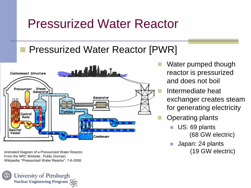
Pressurized Water Reactor
Animated Diagram of a Pressurized Water Reactor.
From the NRC Website. Public Domain.
Wikipedia: “Pressurized Water Reactor”, 1-6-2008
Pressurized Water Reactor [PWR]
Water pumped though
reactor is pressurized
and does not boil
Intermediate heat
exchanger creates steam
for generating electricity
Operating plants
US: 69 plants
(68 GW electric)
Japan: 24 plants
(19 GW electric)
Nuclear Engineering Program
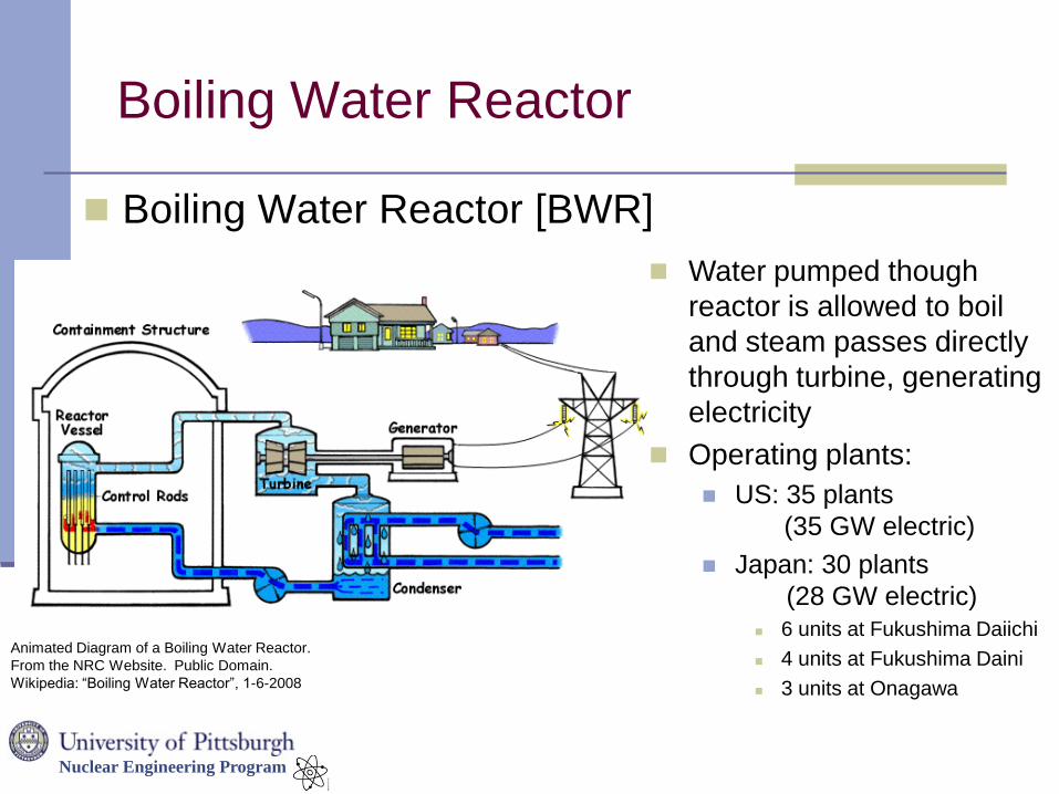
Boiling Water Reactor
Boiling Water Reactor [BWR]
Water pumped though
reactor is allowed to boil
and steam passes directly
through turbine, generating
electricity
Operating plants:
US: 35 plants
(35 GW electric)
Japan: 30 plants
(28 GW electric) 6 units at Fukushima Daiichi
4 units at Fukushima Daini
3 units at Onagawa
Animated Diagram of a Boiling Water Reactor.
From the NRC Website. Public Domain.
Wikipedia: “Boiling Water Reactor”, 1-6-2008
Nuclear Engineering Program
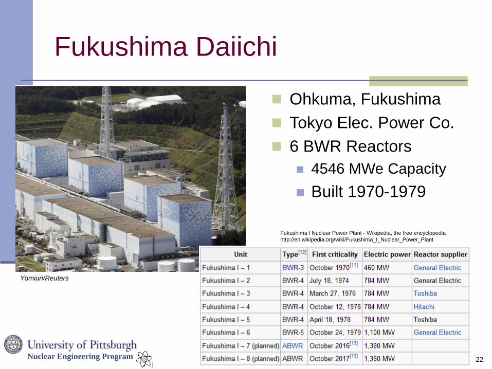
Fukushima Daiichi
22
Yomiuri/Reuters
Ohkuma, Fukushima
Tokyo Elec. Power Co.
6 BWR Reactors
4546 MWe Capacity
Built 1970-1979
Fukushima I Nuclear Power Plant - Wikipedia, the free encyclopedia
http://en.wikipedia.org/wiki/Fukushima_I_Nuclear_Power_Plant
Nuclear Engineering Program
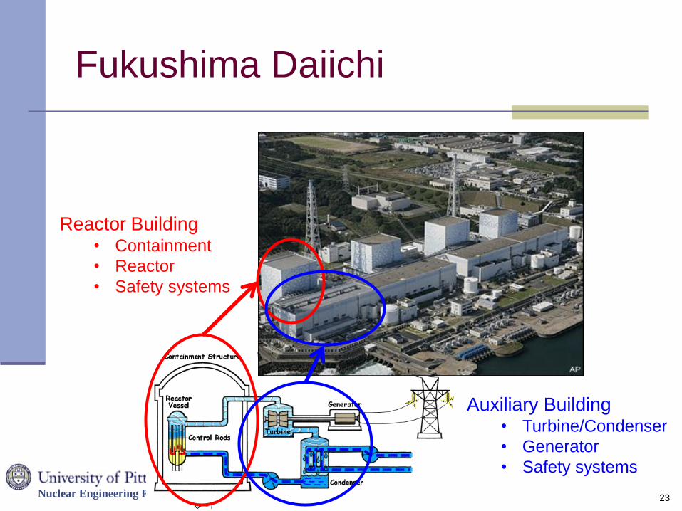
Fukushima Daiichi
23
Reactor Building • Containment
• Reactor
• Safety systems
Auxiliary Building • Turbine/Condenser
• Generator
• Safety systems
Nuclear Engineering Program
Reactor Safety
During reactor design a tremendous amount of effort
is spent on safety analysis
Understanding how plant will behave in off-normal situations
Designing active and passive safety systems to ensure plant
can respond to abnormal conditions
Before construction every plant design must be
approved by regulatory agency
Builder must prove (via analysis) that plant can withstand a
set of site-specific design-basis accidents set defined or
approved by the regulator.
24
Nuclear Engineering Program
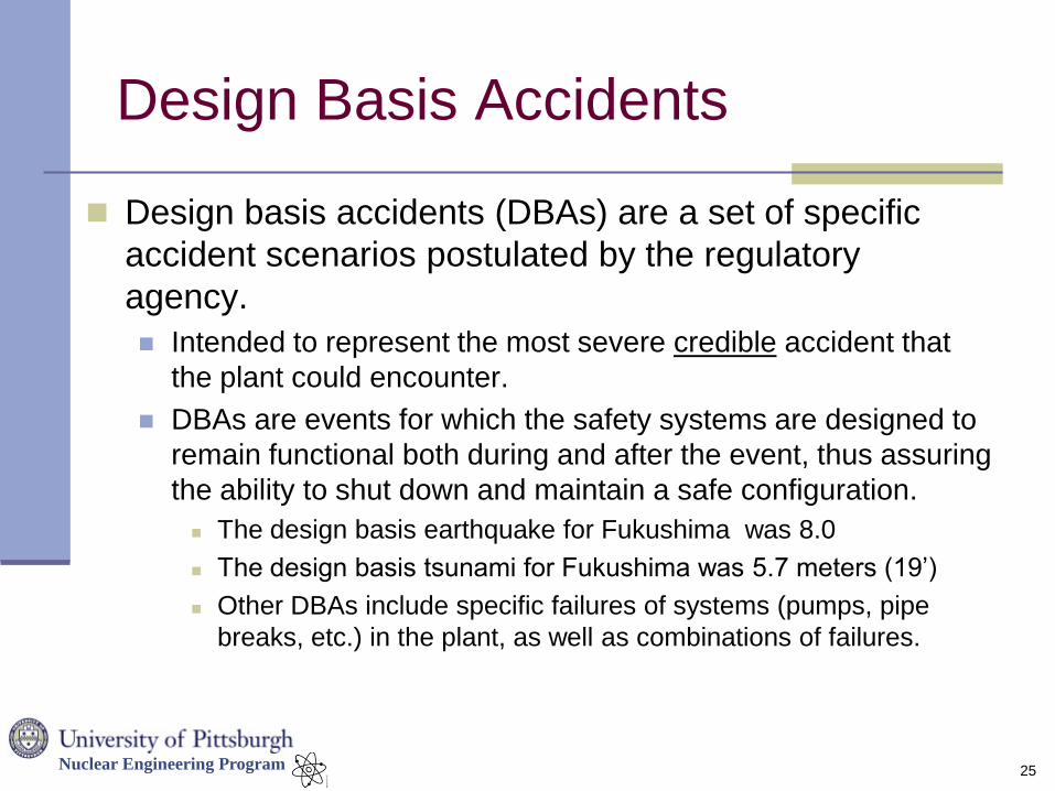
Design Basis Accidents
Design basis accidents (DBAs) are a set of specific
accident scenarios postulated by the regulatory
agency.
Intended to represent the most severe credible accident that
the plant could encounter.
DBAs are events for which the safety systems are designed to
remain functional both during and after the event, thus assuring
the ability to shut down and maintain a safe configuration.
The design basis earthquake for Fukushima was 8.0
The design basis tsunami for Fukushima was 5.7 meters (19’)
Other DBAs include specific failures of systems (pumps, pipe
breaks, etc.) in the plant, as well as combinations of failures.
25
Nuclear Engineering Program
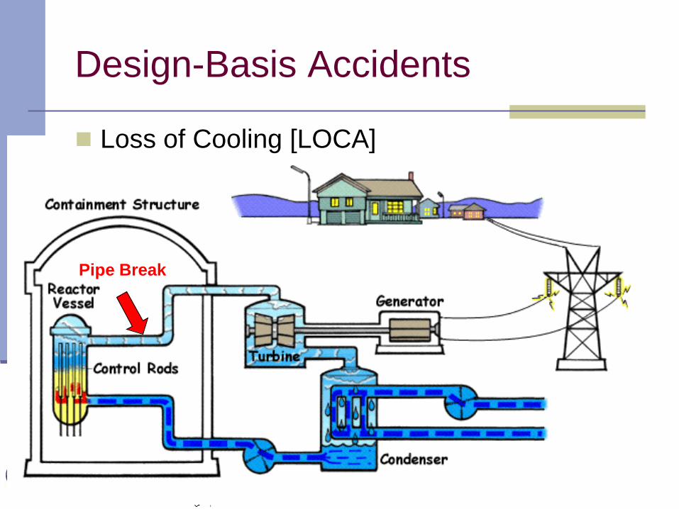
Design-Basis Accidents
Loss of Cooling [LOCA]
Pipe Break
Nuclear Engineering Program
Design-Basis Accidents
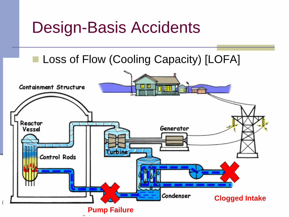
Loss of Flow (Cooling Capacity) [LOFA]
Pump Failure
Clogged Intake
Nuclear Engineering Program
Reactor Safety Systems
In order to satisfy DBA requirements, reactors are
designed with a wide variety of active and passive
safety features to: Ensure that the chain reaction can be stopped in all credible scenarios
Prevent fuel from melting in all credible scenarios
Reactor designs also employ a Defense-in-Depth
philosophy to prevent (or minimize) the release of
radioactive material in severe accidents
Defense-in-Depth is inherent in the reactor design itself
Choice of materials
Plant designed with physical “layers” of defense
Layout of plant itself
28
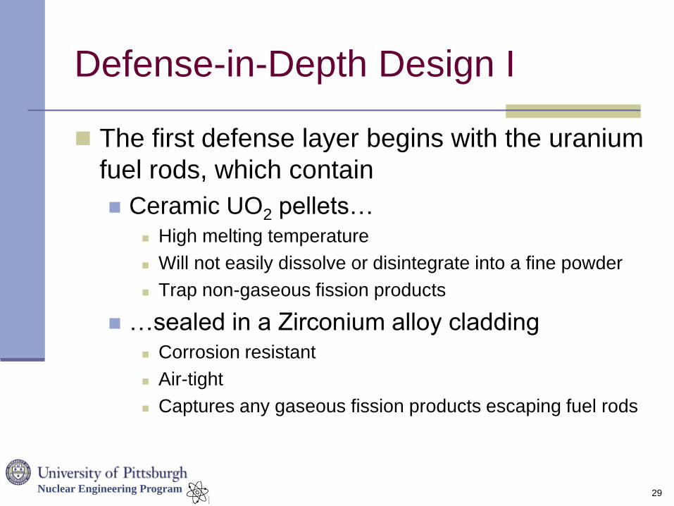
Nuclear Engineering Program
Defense-in-Depth Design I
The first defense layer begins with the uranium
fuel rods, which contain
Ceramic UO2 pellets… High melting temperature
Will not easily dissolve or disintegrate into a fine powder
Trap non-gaseous fission products
…sealed in a Zirconium alloy cladding Corrosion resistant
Air-tight
Captures any gaseous fission products escaping fuel rods
29
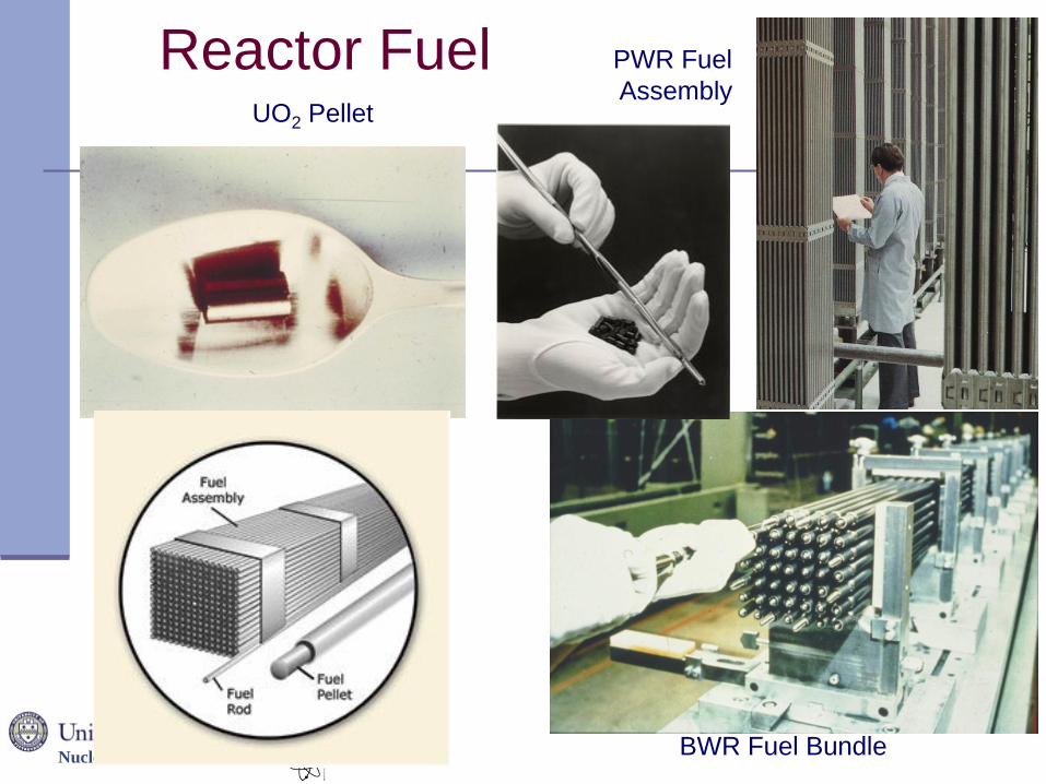
Nuclear Engineering Program
Reactor Fuel PWR Fuel
Assembly UO2 Pellet
BWR Fuel Bundle
Nuclear Engineering Program
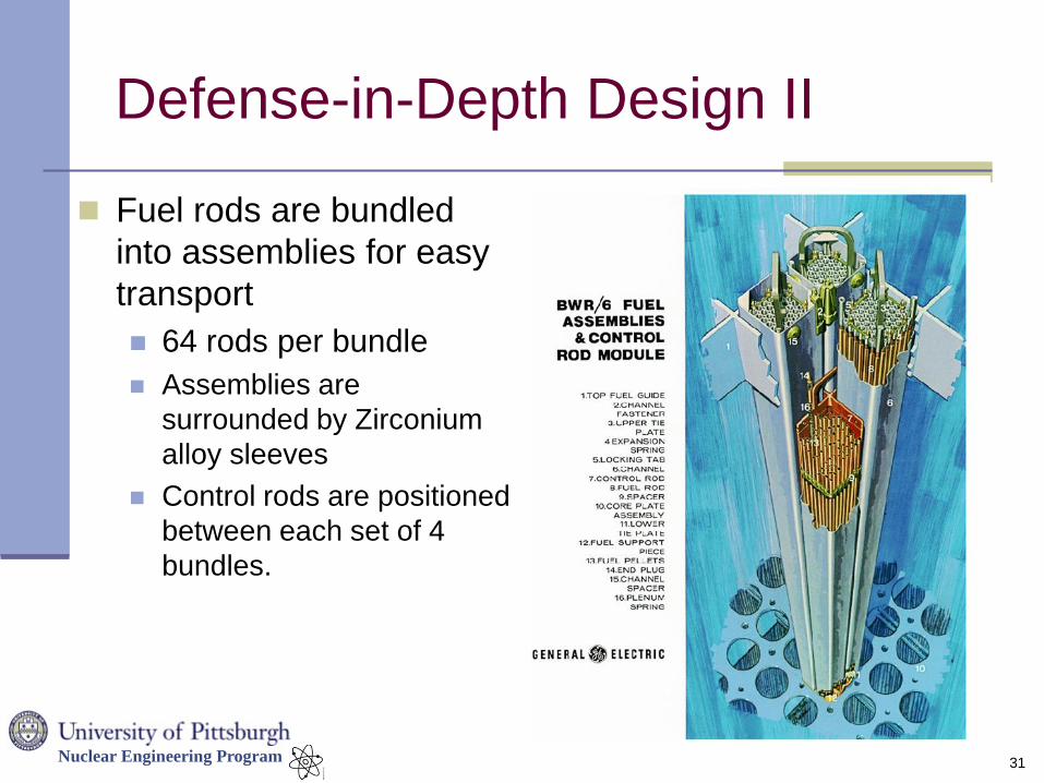
Defense-in-Depth Design II
31
Fuel rods are bundled
into assemblies for easy
transport
64 rods per bundle
Assemblies are
surrounded by Zirconium
alloy sleeves
Control rods are positioned
between each set of 4
bundles.
Nuclear Engineering Program
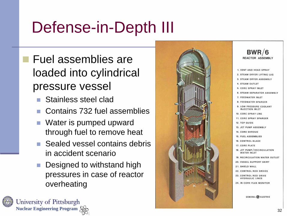
Defense-in-Depth III
Fuel assemblies are
loaded into cylindrical
pressure vessel Stainless steel clad
Contains 732 fuel assemblies
Water is pumped upward
through fuel to remove heat
Sealed vessel contains debris
in accident scenario
Designed to withstand high
pressures in case of reactor
overheating
32
Nuclear Engineering Program
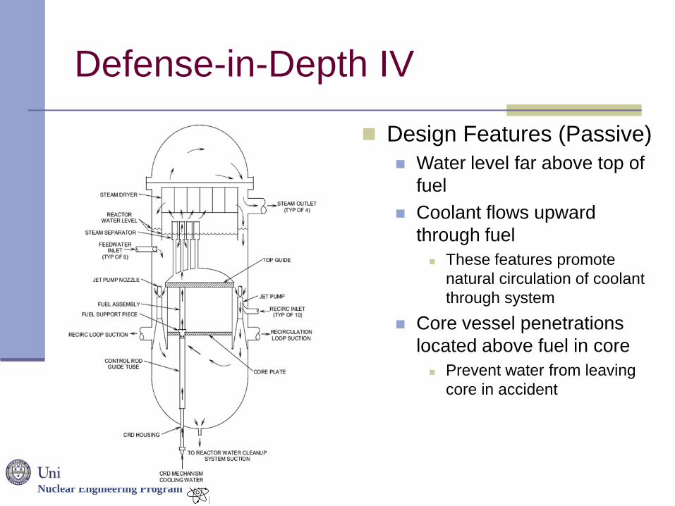
Defense-in-Depth IV
33
Design Features (Passive)
Water level far above top of
fuel
Coolant flows upward
through fuel
These features promote
natural circulation of coolant
through system
Core vessel penetrations
located above fuel in core
Prevent water from leaving
core in accident
Nuclear Engineering Program
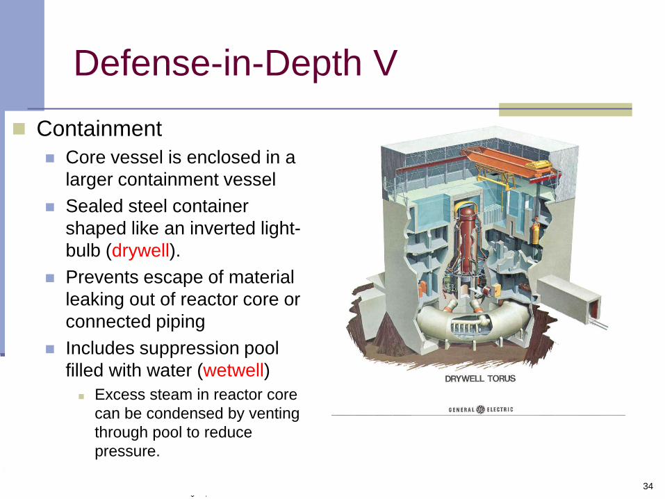
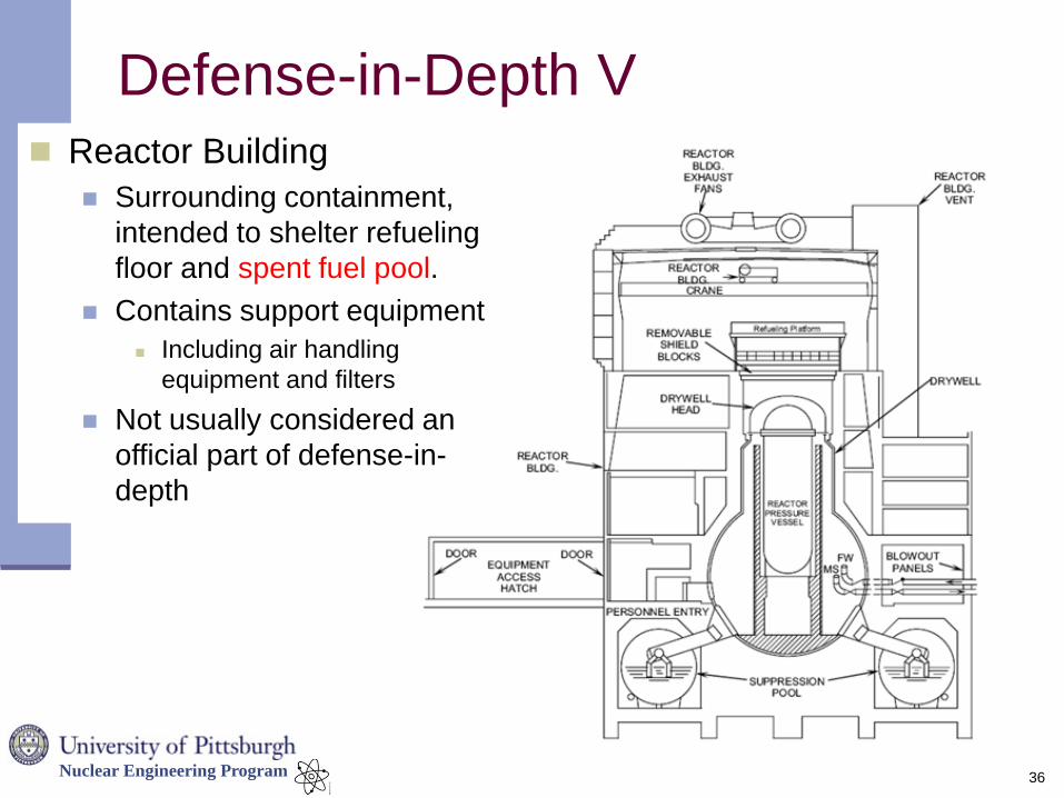
Defense-in-Depth V
34
Containment
Core vessel is enclosed in a
larger containment vessel
Sealed steel container
shaped like an inverted light-
bulb (drywell).
Prevents escape of material
leaking out of reactor core or
connected piping
Includes suppression pool
filled with water (wetwell)
Excess steam in reactor core
can be condensed by venting
through pool to reduce
pressure.
Nuclear Engineering Program 35
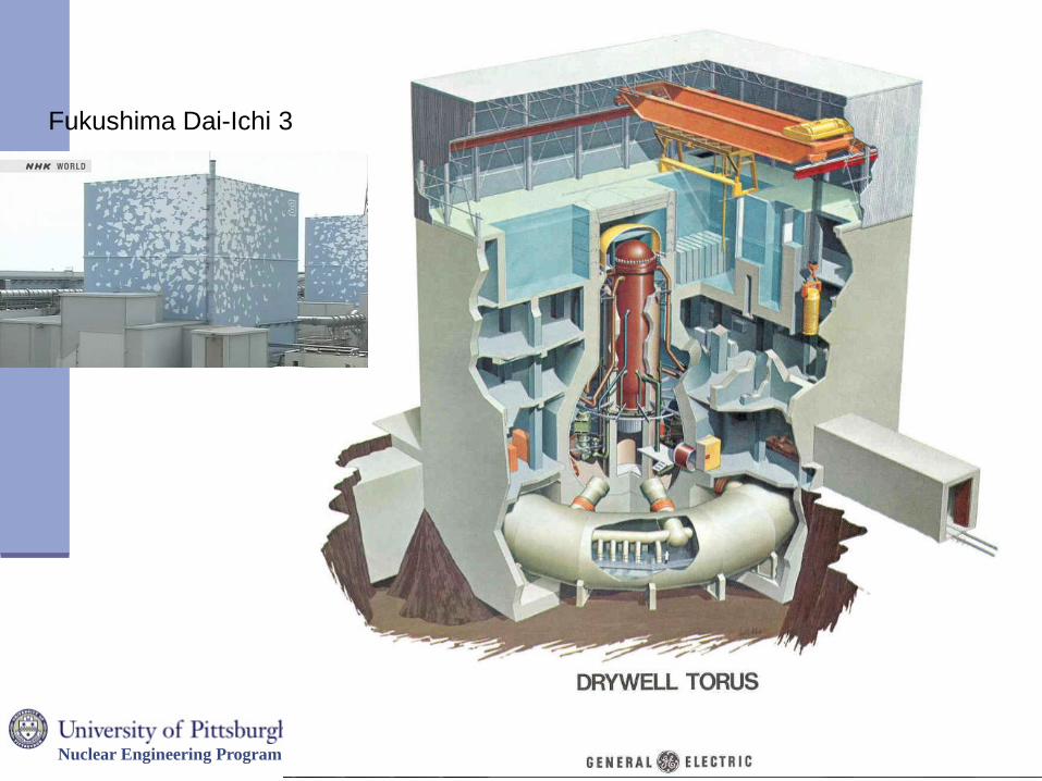
Fukushima Dai-Ichi 3
Nuclear Engineering Program 36
Reactor Building
Surrounding containment,
intended to shelter refueling
floor and spent fuel pool.
Contains support equipment
Including air handling
equipment and filters
Not usually considered an
official part of defense-in-
depth
Defense-in-Depth V
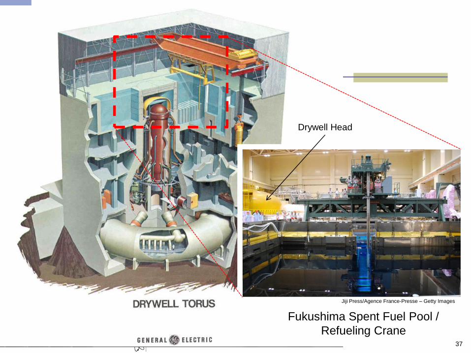
Nuclear Engineering Program 37
Fukushima Spent Fuel Pool /
Refueling Crane
Drywell Head
Jiji Press/Agence France-Presse – Getty Images
Nuclear Engineering Program
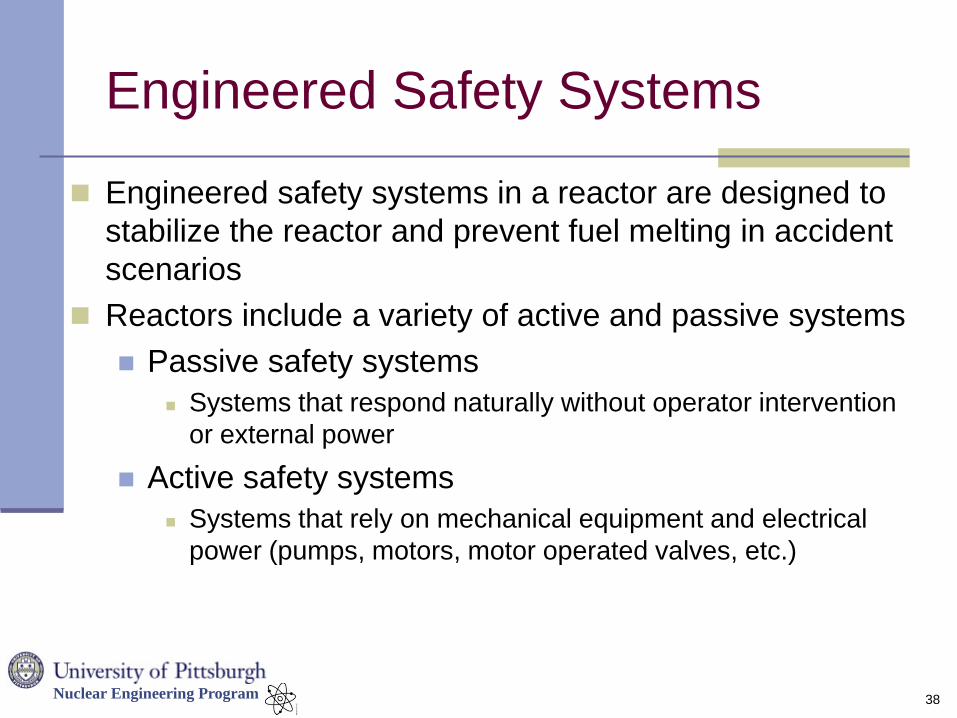
Engineered Safety Systems
Engineered safety systems in a reactor are designed to
stabilize the reactor and prevent fuel melting in accident
scenarios
Reactors include a variety of active and passive systems
Passive safety systems
Systems that respond naturally without operator intervention
or external power
Active safety systems
Systems that rely on mechanical equipment and electrical
power (pumps, motors, motor operated valves, etc.)
38
Nuclear Engineering Program
Engineered Safety Systems
In order to minimize the risk of engineered safety
systems failing, nuclear plant designs emphasize
Redundancy / Flexibility
Is there a back-up component that can do the task if the
primary fails to start? Can the system be reconfigured to
handle unusual conditions or multiple failures?
Diversity
Having multiple different types of active safety systems
provides extra insurance
Physical Separation
Making sure that safety systems are spread around the plant
reduces the risk that an accident can damage all of the
systems
39
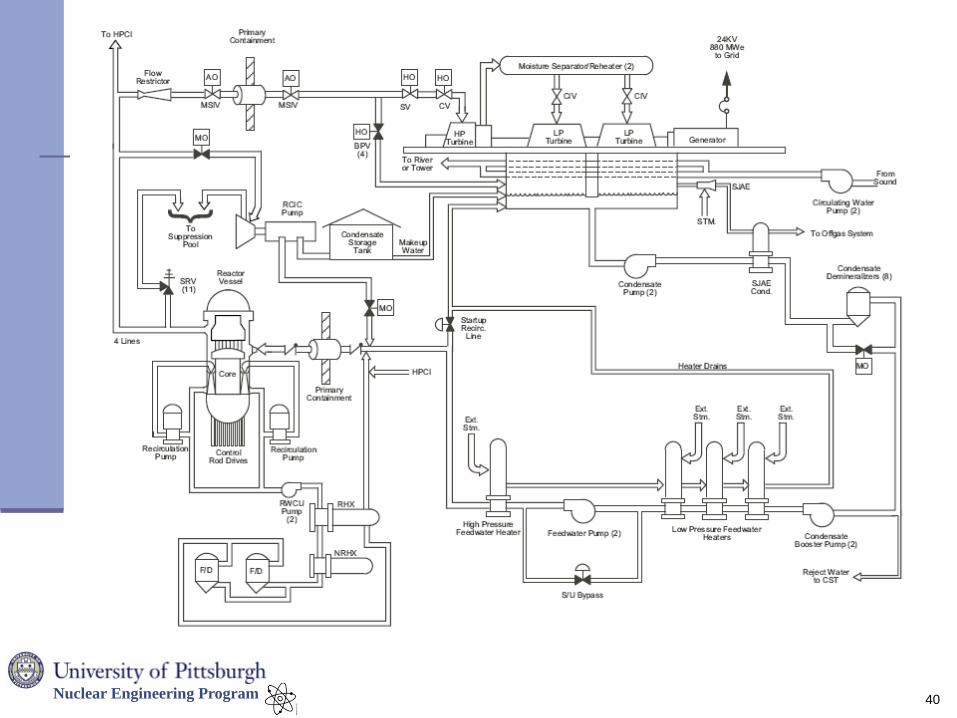
Nuclear Engineering Program
40

Nuclear Engineering Program
41
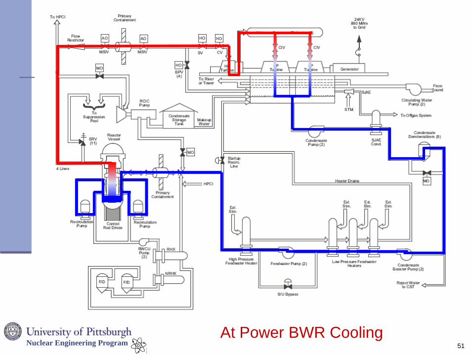
At Power BWR Cooling
Nuclear Engineering Program
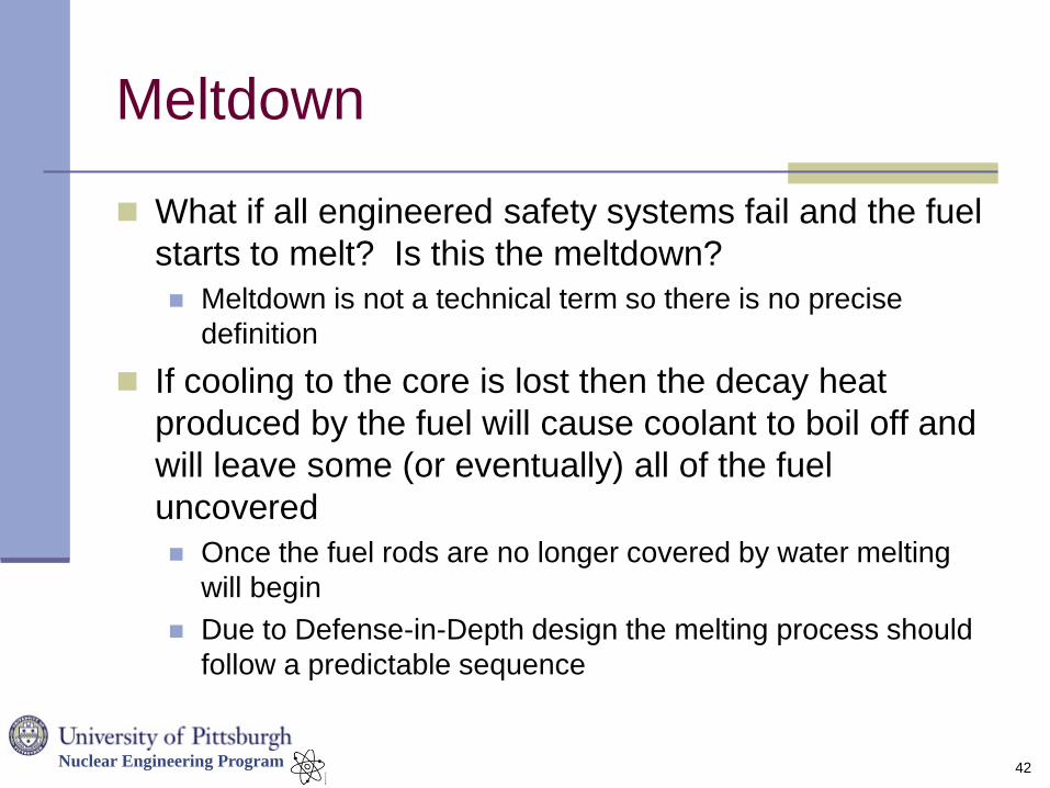
Meltdown
What if all engineered safety systems fail and the fuel
starts to melt? Is this the meltdown?
Meltdown is not a technical term so there is no precise
definition
If cooling to the core is lost then the decay heat
produced by the fuel will cause coolant to boil off and
will leave some (or eventually) all of the fuel
uncovered
Once the fuel rods are no longer covered by water melting
will begin
Due to Defense-in-Depth design the melting process should
follow a predictable sequence
42
Nuclear Engineering Program
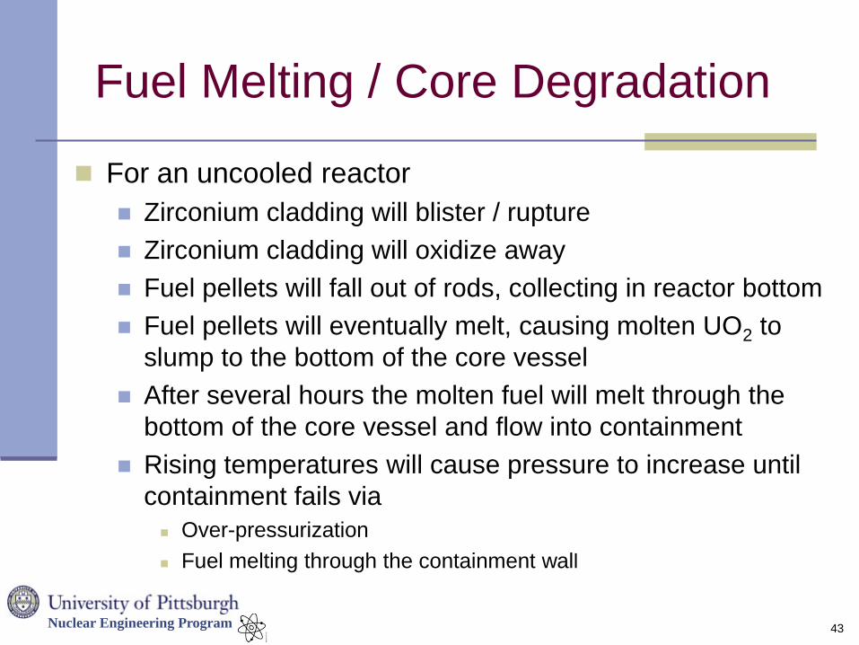
Fuel Melting / Core Degradation
For an uncooled reactor
Zirconium cladding will blister / rupture
Zirconium cladding will oxidize away
Fuel pellets will fall out of rods, collecting in reactor bottom
Fuel pellets will eventually melt, causing molten UO2 to
slump to the bottom of the core vessel
After several hours the molten fuel will melt through the
bottom of the core vessel and flow into containment
Rising temperatures will cause pressure to increase until
containment fails via
Over-pressurization
Fuel melting through the containment wall
43
Nuclear Engineering Program
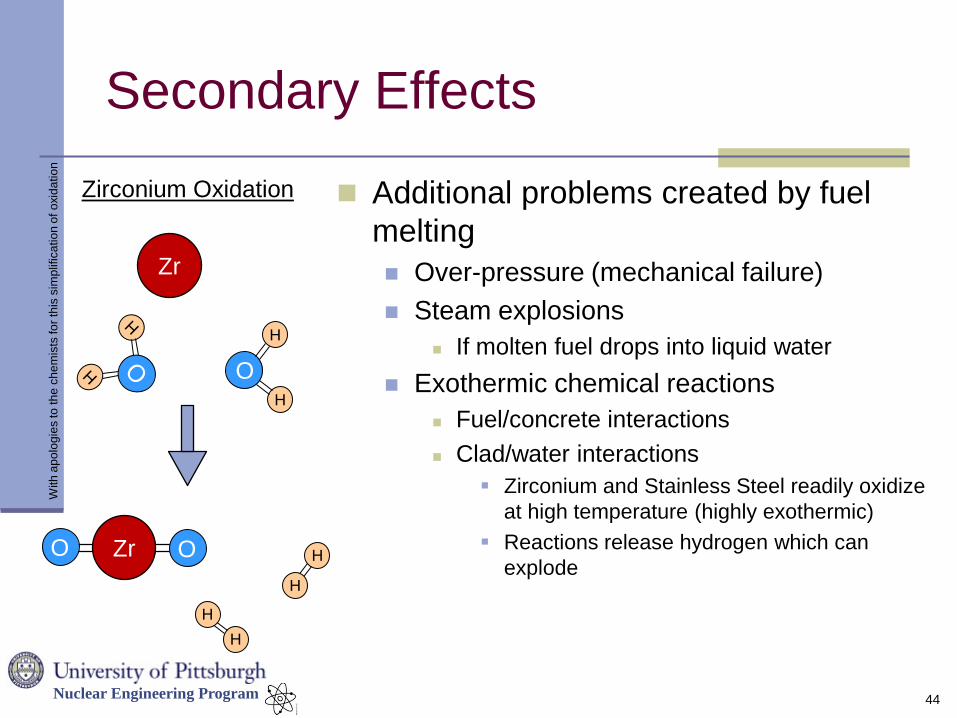
Secondary Effects
Additional problems created by fuel
melting
Over-pressure (mechanical failure)
Steam explosions
If molten fuel drops into liquid water
Exothermic chemical reactions
Fuel/concrete interactions
Clad/water interactions
Zirconium and Stainless Steel readily oxidize
at high temperature (highly exothermic)
Reactions release hydrogen which can
explode
44
Zr
O
H
H
Zirconium Oxidation
Zr O O H
H
H
H
With
ap
olo
gie
s to
th
e c
he
mis
ts fo
r th
is s
imp
lific
atio
n o
f o
xid
atio
n
Nuclear Engineering Program
Environmental Release
Once containment fails, radioactive materials (molten
fuel and gaseous fission products) have entered the
environment.
The real dangers:
Many fission products are radioactive and others are
quite toxic
An uncontrolled environmental release means that
these nuclides can be inhaled directly or ingested by
eating contaminated food
45
Nuclear Engineering Program
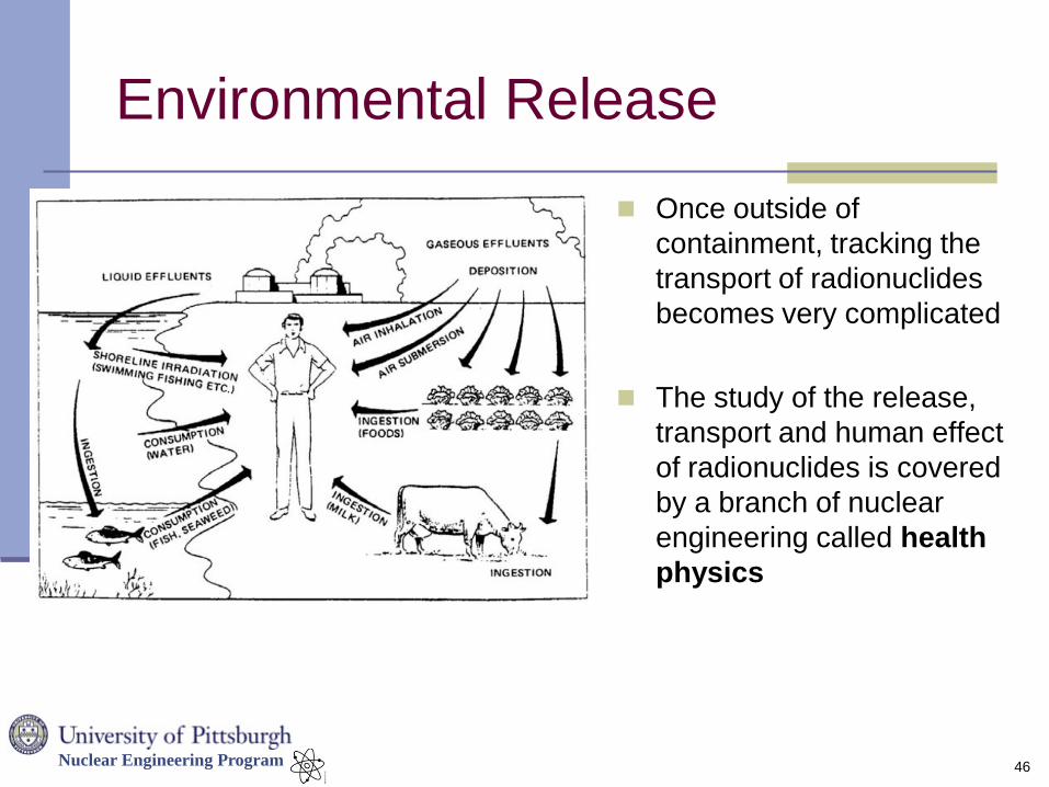
Environmental Release
Once outside of
containment, tracking the
transport of radionuclides
becomes very complicated
The study of the release,
transport and human effect
of radionuclides is covered
by a branch of nuclear
engineering called health
physics
46
Nuclear Engineering Program
Environmental Release
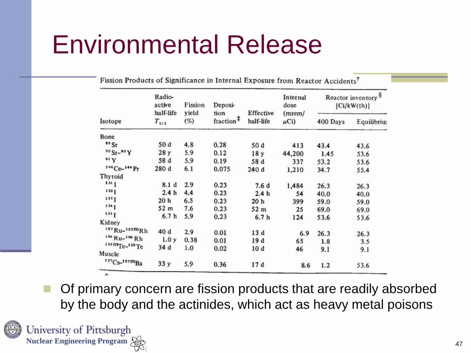
Of primary concern are fission products that are readily absorbed
by the body and the actinides, which act as heavy metal poisons
47
Nuclear Engineering Program
Has Nuclear Fuel Ever Melted?
Unfortunately, yes.
There have actually been ~50-100 reactor
accidents over the last 60 years
Many in Russia, but a surprisingly large number
in the US (mostly in research reactors during the
first two decades)
Most were minor, with a small amount of fuel
damage (most reactors were refueled and
returned to service)
Four accidents stand out above the rest
48
Nuclear Engineering Program
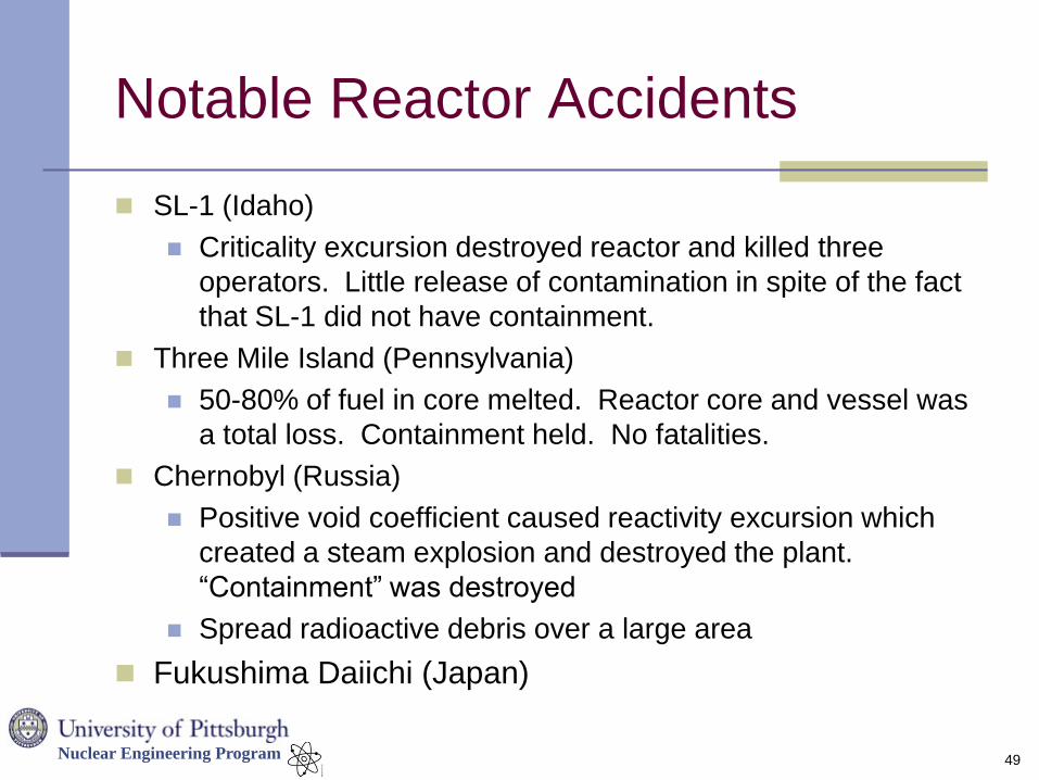
Notable Reactor Accidents
SL-1 (Idaho)
Criticality excursion destroyed reactor and killed three
operators. Little release of contamination in spite of the fact
that SL-1 did not have containment.
Three Mile Island (Pennsylvania)
50-80% of fuel in core melted. Reactor core and vessel was
a total loss. Containment held. No fatalities.
Chernobyl (Russia)
Positive void coefficient caused reactivity excursion which
created a steam explosion and destroyed the plant.
“Containment” was destroyed
Spread radioactive debris over a large area
Fukushima Daiichi (Japan)
49
Nuclear Engineering Program
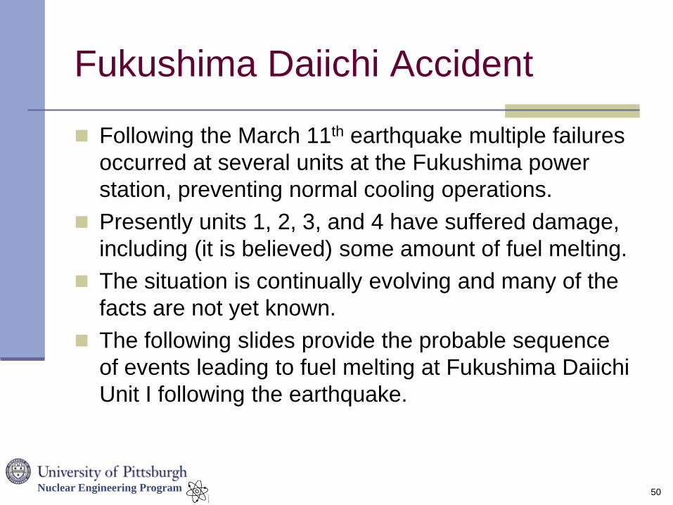
Fukushima Daiichi Accident
Following the March 11th earthquake multiple failures
occurred at several units at the Fukushima power
station, preventing normal cooling operations.
Presently units 1, 2, 3, and 4 have suffered damage,
including (it is believed) some amount of fuel melting.
The situation is continually evolving and many of the
facts are not yet known.
The following slides provide the probable sequence
of events leading to fuel melting at Fukushima Daiichi
Unit I following the earthquake.
50
Nuclear Engineering Program
51
At Power BWR Cooling
Nuclear Engineering Program
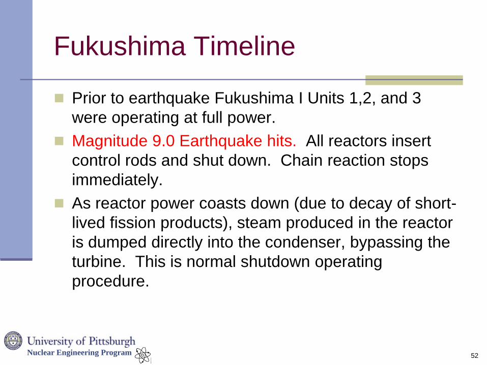
Fukushima Timeline
Prior to earthquake Fukushima I Units 1,2, and 3
were operating at full power.
Magnitude 9.0 Earthquake hits. All reactors insert
control rods and shut down. Chain reaction stops
immediately.
As reactor power coasts down (due to decay of short-
lived fission products), steam produced in the reactor
is dumped directly into the condenser, bypassing the
turbine. This is normal shutdown operating
procedure.
52
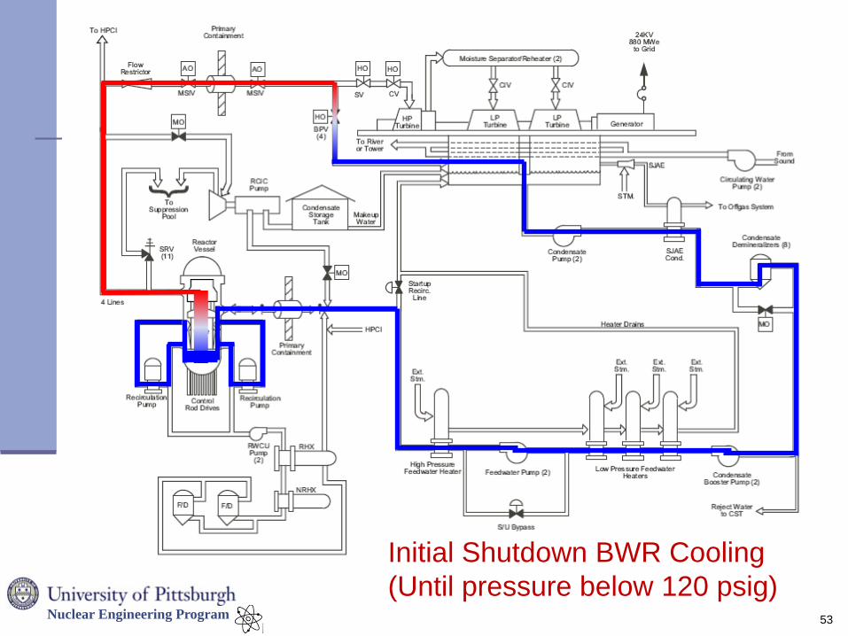
Nuclear Engineering Program
53
Initial Shutdown BWR Cooling
(Until pressure below 120 psig)
Nuclear Engineering Program
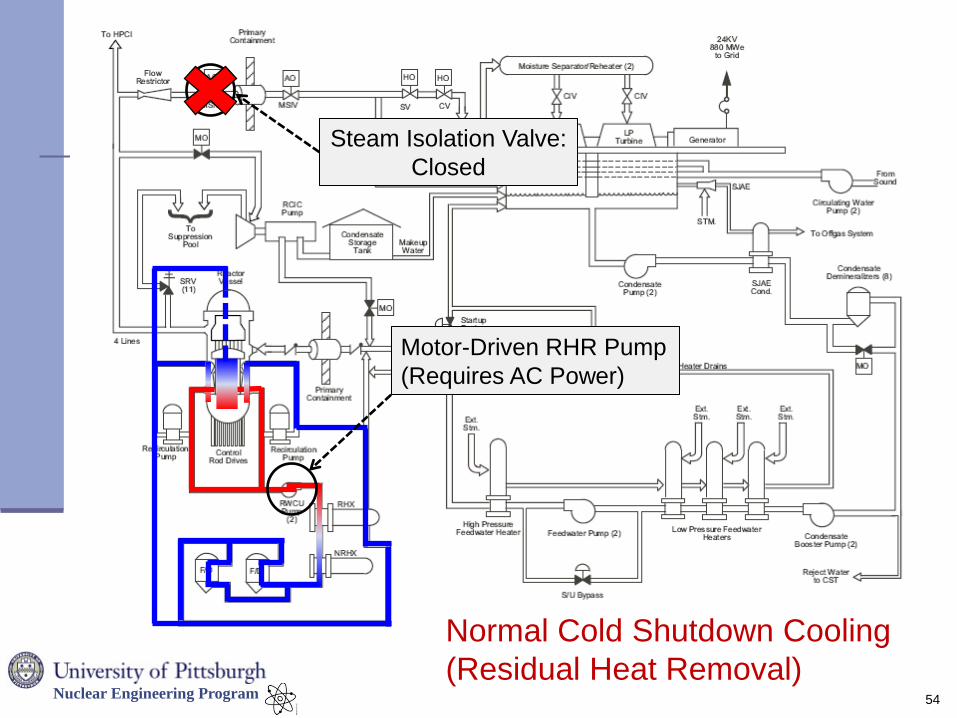
54
Normal Cold Shutdown Cooling
(Residual Heat Removal)
Motor-Driven RHR Pump
(Requires AC Power)
Steam Isolation Valve:
Closed
Nuclear Engineering Program
Fukushima I – Unit 1 Timeline
Power lines and distribution yard are destroyed
causing loss of off-site power.
First off-normal condition
Probably due to shaking from earthquake.
Loss of off-site power is an anticipated scenario and
nuclear plants are well trained to respond.
Emergency diesel generators kick in to support in-
house electrical loads for core cooling.
Circulating water pumps (to cool condenser) are not
powered by emergency diesel generators.
55
Nuclear Engineering Program
Fukushima I – Unit 1 Timeline
During loss of off-site power circulating water pumps (to cool
condenser) shut down, as designed.
Main steam isolation valves are closed, routing steam away from
the main condenser
The Reactor Core Isolation Cooling (RCIC) System, a passive
backup cooling system, takes over core cooling, as designed
RCIC uses turbine driven pumps powered by steam created in reactor
Condenses steam to suppression pool
Draws feedwater from suppression pool and external condensate tank
RCIC system requires DC power to keep motor operated valves in the
open position (fail-safe valve position is closed.)
56
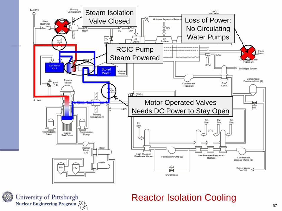
Nuclear Engineering Program
57
Reactor Isolation Cooling
Stored
Water
Supression
Pool
Loss of Power:
No Circulating
Water Pumps
RCIC Pump
Steam Powered
Motor Operated Valves
Needs DC Power to Stay Open
Steam Isolation
Valve Closed
Nuclear Engineering Program
Fukushima I – Unit 1 Timeline
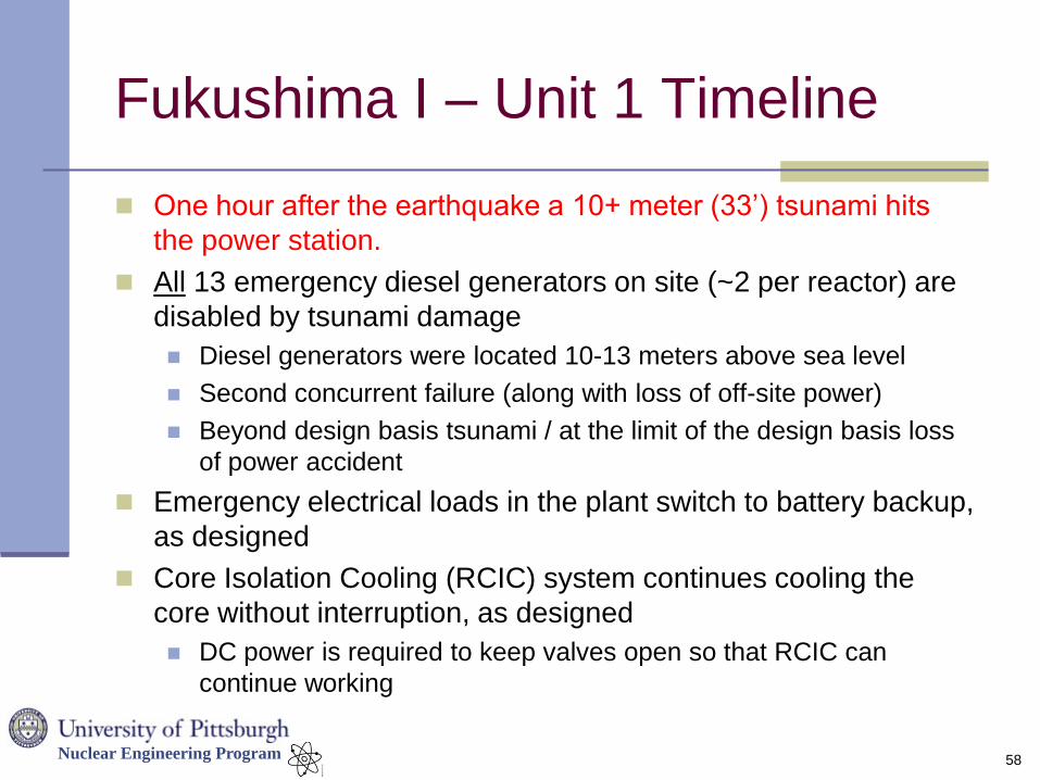
One hour after the earthquake a 10+ meter (33’) tsunami hits
the power station.
All 13 emergency diesel generators on site (~2 per reactor) are
disabled by tsunami damage
Diesel generators were located 10-13 meters above sea level
Second concurrent failure (along with loss of off-site power)
Beyond design basis tsunami / at the limit of the design basis loss
of power accident
Emergency electrical loads in the plant switch to battery backup,
as designed
Core Isolation Cooling (RCIC) system continues cooling the
core without interruption, as designed
DC power is required to keep valves open so that RCIC can
continue working
58
Nuclear Engineering Program
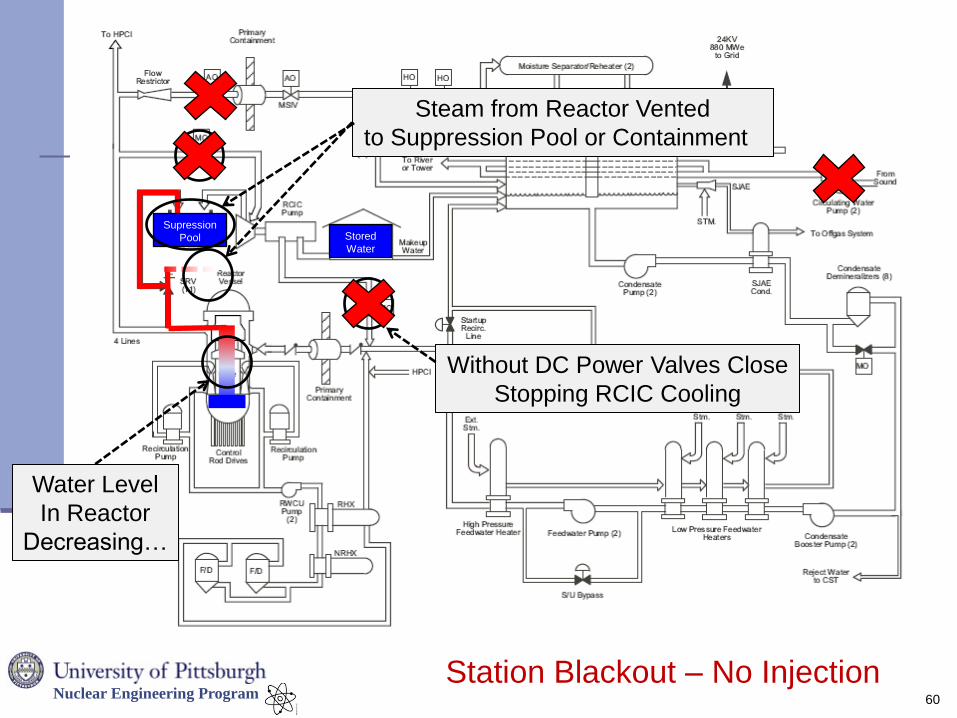
Fukushima I – Unit 1 Timeline
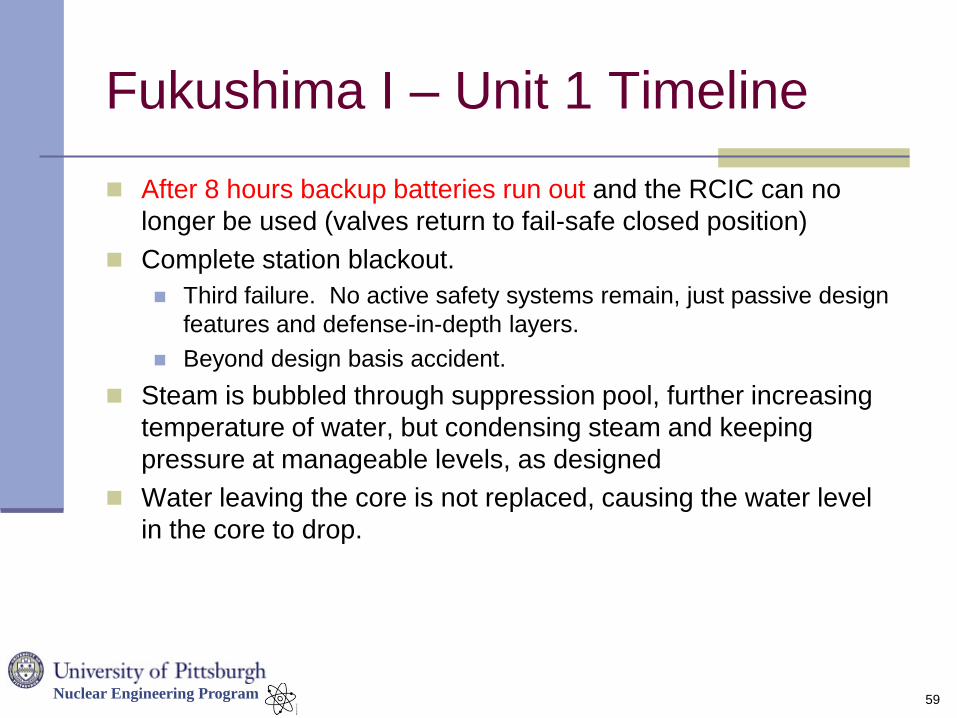
After 8 hours backup batteries run out and the RCIC can no
longer be used (valves return to fail-safe closed position)
Complete station blackout.
Third failure. No active safety systems remain, just passive design
features and defense-in-depth layers.
Beyond design basis accident.
Steam is bubbled through suppression pool, further increasing
temperature of water, but condensing steam and keeping
pressure at manageable levels, as designed
Water leaving the core is not replaced, causing the water level
in the core to drop.
59
Nuclear Engineering Program
60
Stored
Water
Supression
Pool
Station Blackout – No Injection
Without DC Power Valves Close
Stopping RCIC Cooling
Steam from Reactor Vented
to Suppression Pool or Containment
Water Level
In Reactor
Decreasing…
Nuclear Engineering Program
Fukushima I – Unit 1 Timeline
As the water level dropped below the top of the fuel, the
temperature in the fuel and cladding began to rise rapidly,
causing fuel degradation
Clad failure (blister/rupture) allows gaseous fission products in fuel
to escape
Zirconium in clad oxidizes in the presence of water, releasing
hydrogen into containment drywell
Uncertain how much fuel was uncovered by water or how much
melting has taken place.
During the station blackout, operators focused on the third layer
of defense: containment
No matter what happens in the core, prevent release of material to
the environment
61
Nuclear Engineering Program
Fukushima I – Unit 1 Timeline
After a short time pressure levels in containment
were at or above the design pressure, raising the risk
of a containment rupture due to over-pressurization
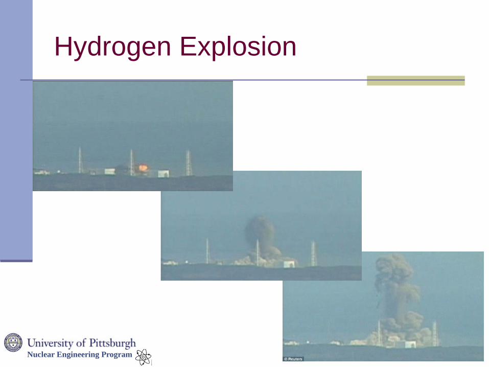
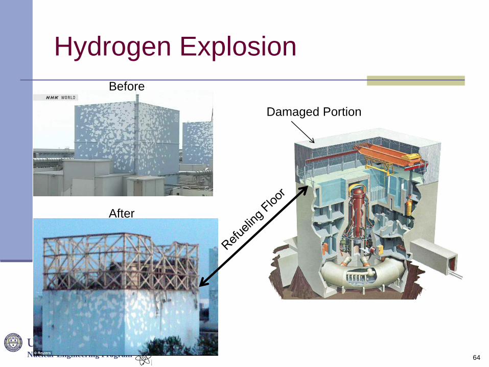
Operators manually opened a valve to release steam
from containment into the reactor building.
This was done to prevent an overpressure of containment
and the possible uncontrolled release of radioactive material.
Vented steam contained hydrogen, which ignited, destroying
the reactor building, but not damaging containment…
…but, spent fuel pool is now exposed to the elements
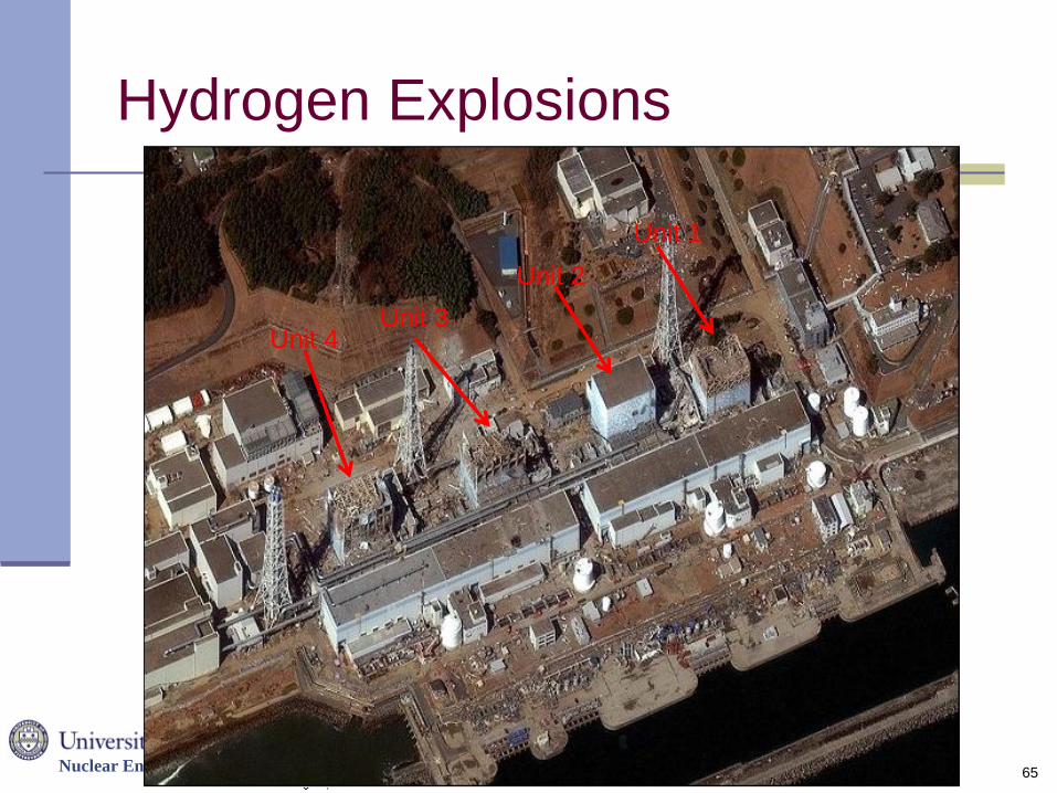
Units 3 and 4 later suffer similar explosions
62
Nuclear Engineering Program
Hydrogen Explosion
63
Nuclear Engineering Program
Hydrogen Explosion
64
Before
After
Damaged Portion
Nuclear Engineering Program
Hydrogen Explosions
65
Unit 3 Unit 4
Unit 1
Unit 2
Nuclear Engineering Program
Fukushima I – Unit 1 Timeline
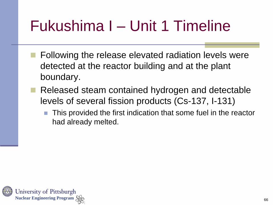
Following the release elevated radiation levels were
detected at the reactor building and at the plant
boundary.
Released steam contained hydrogen and detectable
levels of several fission products (Cs-137, I-131)
This provided the first indication that some fuel in the reactor
had already melted.
66
Nuclear Engineering Program
Fukushima I – Unit 1 Timeline
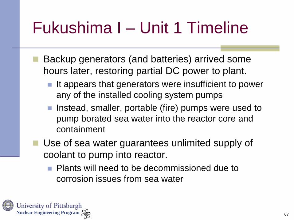
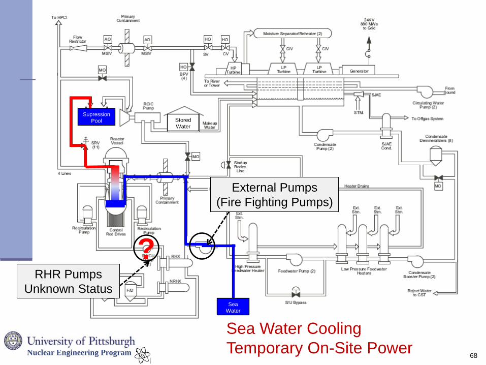
Backup generators (and batteries) arrived some
hours later, restoring partial DC power to plant.
It appears that generators were insufficient to power
any of the installed cooling system pumps
Instead, smaller, portable (fire) pumps were used to
pump borated sea water into the reactor core and
containment
Use of sea water guarantees unlimited supply of
coolant to pump into reactor.
Plants will need to be decommissioned due to
corrosion issues from sea water
67
Nuclear Engineering Program
68
Stored
Water
Supression
Pool
Sea Water Cooling
Temporary On-Site Power
External Pumps
(Fire Fighting Pumps)
? RHR Pumps
Unknown Status Sea
Water
Nuclear Engineering Program
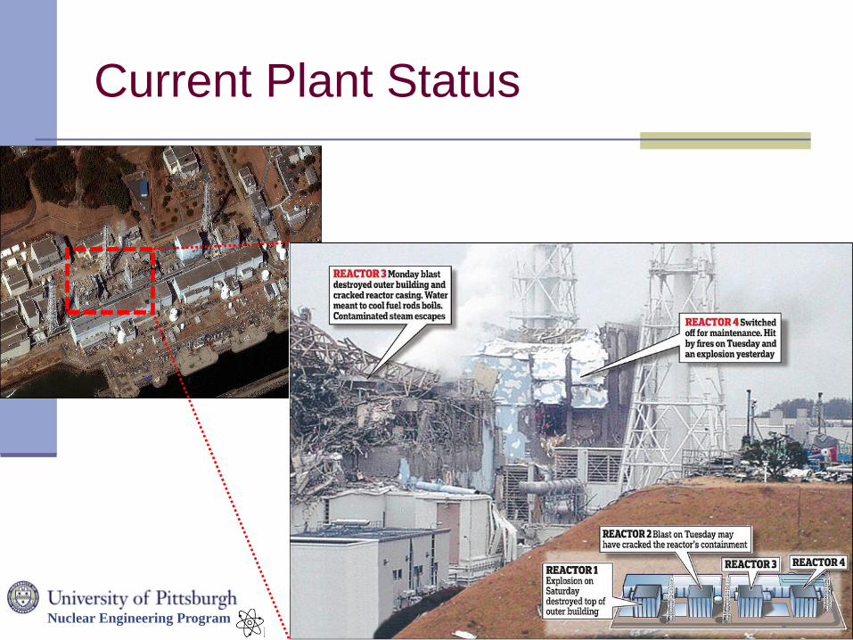
Current Plant Status
69
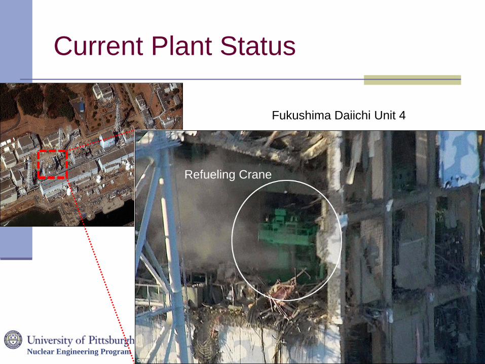
Nuclear Engineering Program
Current Plant Status
70
Fukushima Daiichi Unit 4
Refueling Crane
Nuclear Engineering Program
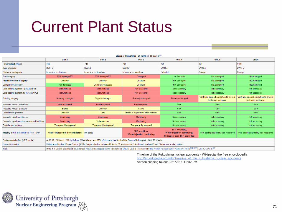
Current Plant Status
71
Timeline of the Fukushima nuclear accidents - Wikipedia, the free encyclopedia
http://en.wikipedia.org/wiki/Timeline_of_the_Fukushima_nuclear_accidents
Screen clipping taken: 3/21/2011 10:32 PM
Nuclear Engineering Program
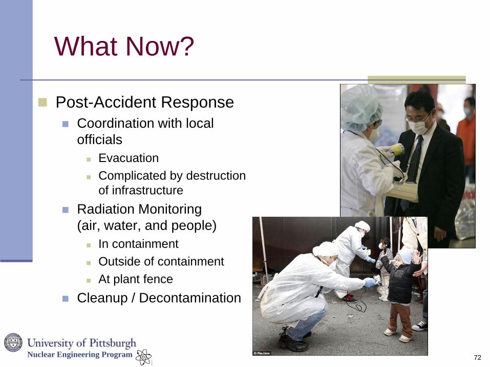
What Now?
72
Post-Accident Response
Coordination with local
officials
Evacuation
Complicated by destruction
of infrastructure
Radiation Monitoring
(air, water, and people)
In containment
Outside of containment
At plant fence
Cleanup / Decontamination
Nuclear Engineering Program
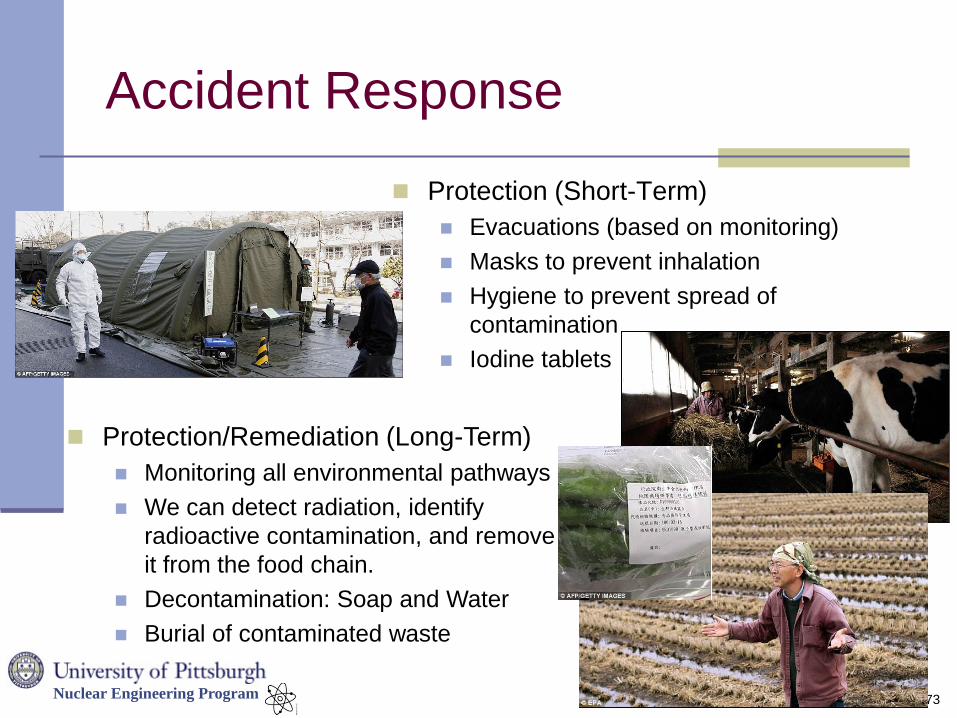
Accident Response
Protection (Short-Term)
Evacuations (based on monitoring)
Masks to prevent inhalation
Hygiene to prevent spread of
contamination
Iodine tablets
73
Protection/Remediation (Long-Term)
Monitoring all environmental pathways
We can detect radiation, identify
radioactive contamination, and remove
it from the food chain.
Decontamination: Soap and Water
Burial of contaminated waste