Embed Size (px)
Citation preview
© Solmaz Zamanishourabi, 2021
Effect of cell size on the quasi-static compressive properties of silicone foams with spherical closed cells
Mémoire
Solmaz Zamanishourabi
Maîtrise en génie chimique - avec mémoire
Maître ès sciences (M. Sc.)
Québec, Canada
Effect of cell size on the quasi-static compressive properties of silicone foams with spherical closed
cells
Mémoire présenté à la Faculté des études supérieures de l'Université Laval dans le cadre du programme de maîtrise en génie chimique
Solmaz Zamanishourabi
Sous la direction de :
Denis Rodrigue, directeur de recherche
iii
Résumé
Dans ce travail, l'effet de la taille des cellules sur les propriétés de compression des mousses de caoutchouc
de silicone avec des cellules sphériques a été étudié expérimentalement. Les mousses ont été fabriquées
en utilisant une résine de silicone et des billes de polystyrène expansé (EPS) par une nouvelle technique.
Les billes ont été mélangées avec la résine réactive et le mélange a été laissé à température ambiante
jusqu'à ce que la résine soit durcie. Ensuite, le matériau solidifié a été chauffé pour rétracter les billes et
former la structure cellulaire. Trois mousses différentes avec des tailles de cellules différentes, allant
d'environ 1 mm à environ 2 mm, ont été fabriquées et testées sous compression quasi-statique. Pour chaque
échantillon, le module de compression par rapport au poids et la résistance à la compression par rapport
au poids ont été obtenus. Enfin, ces valeurs ont été comparées entre elles pour déterminer l'effet de la taille
des cellules sur les propriétés de compression. Les résultats montrent que l'augmentation de la taille des
cellules augmente la rigidité. Par exemple, l'augmentation de la taille des cellules de 1 mm à 1,5 mm à
densité constante (480 kg/m3) augmente le module de compression de 17%, tandis que la contrainte de
compression à 50% de déformation augmente de 14%. De tous les résultats obtenus, on peut conclure que
parmi les mousses de caoutchouc à cellules fermées ayant la même composition de matrice et des densités
similaires, mais des tailles d'alvéoles différentes, celle ayant la plus petite taille d'alvéole donne les
propriétés de compression les plus faibles par rapport au poids, tandis que celle ayant la plus grande taille
d'alvéole donne le rapport le plus élevé lorsqu'elles sont lentement comprimées.
iv
Abstract
In this work, the effect of cell size on the compressive properties of silicone rubber foams with spherical cells
was experimentally studied. The foams were made using a silicone resin and expanded polystyrene beads
(EPS) through a novel technique. The beads were mixed with the reactive resin and the mixture was left at
room temperature until the resin was cured. Then, the solidified material was heated up to shrink down the
beads to form the cellular structure. Three different foams with different cell sizes, ranging from about 1 mm
to about 2 mm, were made and tested under quasi-static compression. For each sample, the compressive
modulus to weight ratio and compressive strength to weight ratio were obtained. Finally, these values were
compared between them to determine the effect of cell size on the compressive properties. The results show
that increasing the cell size increases the stiffness. For example, increasing the cell size from 1 mm to 1.5
mm at constant density (480 kg/m3) increases the compressive modulus by 17%, while the compressive
stress at 50% strain increases by 14%. From all the results obtained, it can be concluded that among the
closed cell rubber foams having the same matrix composition and similar densities, but different cell sizes,
the one having the smallest cell size gives the lowest compressive properties to weight ratio, while the one
with the largest cell size gives the highest ratio when they are slowly compressed.
v
Table of contents
Résumé ......................................................................................................................................... iii
Abstract ......................................................................................................................................... iv
List of Figures ............................................................................................................................... vii
List of Tables .................................................................................................................................. x
List of abbreviations ....................................................................................................................... xi
List of symbols .............................................................................................................................. xiii
Acknowledgements ...................................................................................................................... xv
Introduction ..................................................................................................................................... 1
POLYMER FOAMS ........................................................................................................................ 1
BLOWING AGENTS ....................................................................................................................... 3
OTHER COMMON POLYMER FOAMS .............................................................................................. 4
BIODEGRADABLE FOAMS .............................................................................................................. 4
SILICONE RUBBER FOAMS ........................................................................................................... 5
STATEMENT OF THE PROBLEM ..................................................................................................... 6
OBJECTIVES OF THE STUDY ......................................................................................................... 8
SCOPE OF THE STUDY ................................................................................................................. 8
SIGNIFICANCE OF THE STUDY ....................................................................................................... 8
Chapter 1 Literature Review .................................................................................................. 10
1.1 INTRODUCTION ................................................................................................................. 10
1.2 COMPRESSION BEHAVIOR OF POLYMER FOAMS ................................................................ 10
1.3 SILICONE RUBBER FOAMING CHEMISTRY .......................................................................... 13
1.4 RECENT SILICONE FOAM DEVELOPMENTS ......................................................................... 17
1.4.1 Silicone Foams Using Physical Foaming Agent ................................................... 17
1.4.1.1 Syntactic Silicone Foams ................................................................................ 18
1.4.1.2 Silicone Foams Using Physical Blowing Agent ............................................... 20
1.4.2 Silicone foams using chemical foaming agents .................................................... 21
1.5 SUMMARY OF LITERATURE REVIEW ................................................................................... 23
Chapter 2 Research Methodology ......................................................................................... 25
2.1 INTRODUCTION ................................................................................................................. 25
2.2 FABRICATION OF THE SILICONE FOAM SAMPLES ................................................................ 25
2.2.1 Materials ............................................................................................................... 25
2.2.2 Procedure ............................................................................................................. 26
vi
2.3 CHARACTERIZATION AND DATA ANALYSIS ......................................................................... 29
2.3.1 Foam Density ........................................................................................................ 29
2.3.2 Foam Morphology ................................................................................................. 29
2.3.3 Compression Properties ....................................................................................... 30
Chapter 3 Results and discussion ......................................................................................... 33
3.1 INTRODUCTION ................................................................................................................. 33
3.2 FOAM DENSITY MEASUREMENT ........................................................................................ 33
3.3 FOAM MORPHOLOGY ANALYSIS ........................................................................................ 35
3.4 COMPRESSION PROPERTIES ............................................................................................. 37
Conclusions and Recommendations ............................................................................................ 48
CONCLUSIONS ........................................................................................................................... 48
RECOMMENDATIONS FOR FUTURE WORKS ................................................................................. 50
References ................................................................................................................................... 51
vii
List of Figures
Figure I.1 Some examples of silicone foams application in the rail industry [18] .................... 6
Figure I.2 Schematic representation of three rubber foams with different cell sizes subjected to
quasi-static compressive loads. ............................................................................................. 7
Figure 1.1 Typical stress-strain curve for a polymer foam under compression [22]. .............. 11
Figure 1.2 Compressive stress-strain curves of a silicone rubber foam with different STG content
(0 wt% - 40 wt%) [16]. ......................................................................................... 12
Figure 1.3 Chemical structures of PDMS polymer (a) [28], and vinyl terminated PDMS polymer
(b) [29]. ................................................................................................................... 13
Figure 1.4 Silicone rubber products classification based on the processing technology and
curing mechanism [33]. ...................................................................................................... 14
Figure 1.5 Condensation curing mechanism for RTV1 or RTV2 systems (adapted from [25]) 15
Figure 1.6 Addition curing mechanism for RTV-2 systems, adapted from [25]. .................... 16
Figure 1.7 The foaming mechanism of a platinum catalysed silicone foam formulation [13]. . 17
Figure 1.8 SEM image of a syntactic rubber foam made from a polyurethane matrix and
polymeric microsphere [41]. ................................................................................................ 19
Figure 1.9 SEM images of the structure of a silicone foam produced by the hydrogen production
technology [56]. ................................................................................................... 22
Figure 2.1 The three-part mold used for foam sample fabrication. ...................................... 27
Figure 2.2 Schematic view of the foam sample fabrication process. ...................................... 28
Figure 2.3 Fabricated foam samples (S1, S2 and S3) with a thickness of 2 cm and a surface of 12
cm by 20 cm (before heating). ............................................................................................. 28
viii
Figure 2.4 A picture of the gas (nitrogen) pycnometer ULTRAPYC 1200e (Quantachrome
Instruments, USA). ............................................................................................................ 29
Figure 2.5 Pictures of the compression test rig (left) and testing machine (right). ................... 31
Figure 2.6 The specimens produced with a thickness of 2 cm and surface of 4 cm by 4 cm prepared
for compression tests. ........................................................................................................ 31
Figure 2.7 Illustration of compression modulus and compressive-deflection calculations from the
stress-strain curve. ............................................................................................................ 32
Figure 3.1 Averaged densities of the compression tests specimens ...................................... 34
Figure 3.2 The cellular structure of the foam samples at low (left) and high (right) magnifications
........................................................................................................................................ 36
Figure 3.3 Compressive stress-strain curve obtained for the unfoamed silicone rubber. .......... 37
Figure 3.4 Compressive stress-strain curves for sample S1. ................................................ 38
Figure 3.5 Compressive stress-strain curves for sample S2 ................................................. 38
Figure 3.6 Compressive stress-strain curves for sample S3 ................................................. 39
Figure 3.7 The averaged compressive moduli for the foam samples. .................................... 42
Figure 3.8 The averaged compression-deflection (compressive stress at 25% strain) for the foam
samples. ........................................................................................................................... 42
Figure 3.9 The averaged compressive stress at 50% strain for the foam samples. ................. 43
Figure 3.10 The compressive modulus to weight ratio for the foam samples. ......................... 45
Figure 3.11 The compression-deflection (compressive stress at 25% or 0.25 strain) to weight ratio
for the foam samples. ......................................................................................................... 46
Figure 3.12 The compressive stress at 50% strain (0.5 strain) to weight ratio for the foam samples.
........................................................................................................................................ 47

ix
Figure II.1 The effect of cell size on the compressive properties with respect to the sample density.
Sample S1 was made using 1 mm EPS beads, S2 using 1.5 mm and S3 using 2 mm beads. ... 48
x
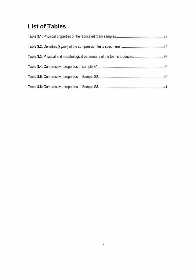
List of Tables
Table 3.1: Physical properties of the fabricated foam samples. ............................................... 33
Table 3.2: Densities (kg/m3) of the compression tests specimens. .......................................... 34
Table 3.3: Physical and morphological parameters of the foams produced. ............................. 36
Table 3.4: Compressive properties of sample S1................................................................... 40
Table 3.5: Compressive properties of Sample S2. ................................................................. 40
Table 3.6: Compressive properties of Sample S3. ................................................................. 41
xi
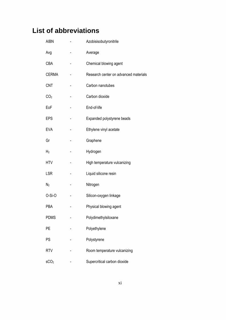
List of abbreviations
AIBN - Azobisisobutyronitrile
Avg - Average
CBA - Chemical blowing agent
CERMA - Research center on advanced materials
CNT - Carbon nanotubes
CO2 - Carbon dioxide
EoF - End-of-life
EPS - Expanded polystyrene beads
EVA - Ethylene vinyl acetate
Gr - Graphene
H2 - Hydrogen
HTV - High temperature vulcanizing
LSR - Liquid silicone resin
N2 - Nitrogen
O-Si-O - Silicon-oxygen linkage
PBA - Physical blowing agent
PDMS - Polydimethylsiloxane
PE - Polyethylene
PS - Polystyrene
RTV - Room temperature vulcanizing
sCO2 - Supercritical carbon dioxide
xii
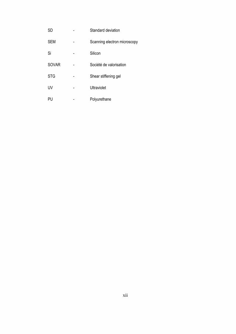
SD - Standard deviation
SEM - Scanning electron microscopy
Si - Silicon
SOVAR - Société de valorisation
STG - Shear stiffening gel
UV - Ultraviolet
PU - Polyurethane
xiii
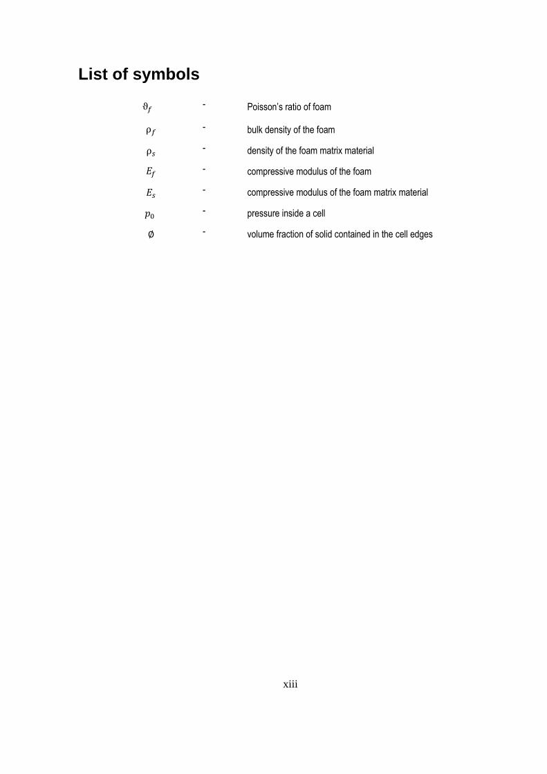
List of symbols
ϑ𝑓 -
Poisson’s ratio of foam
ρ𝑓 -
bulk density of the foam
ρ𝑠 - density of the foam matrix material
𝐸𝑓 -
compressive modulus of the foam
𝐸𝑠 -
compressive modulus of the foam matrix material
𝑝0 -
pressure inside a cell
∅ - volume fraction of solid contained in the cell edges

xiv
To my kind family especially my beloved spouse

xv
Acknowledgements
I would first like to express my sincere gratitude to my supervisor Professor Dr. Denis Rodrigue without
whom this work would never have been done. I sincerely acknowledge his support and guidance throughout
my master program. I would also like to thank the Department of Chemical Engineering of Université Laval
for providing me with exceptional academic opportunities. Finally, I want to thank CERMA (research center
on advanced materials) for technical support and SOVAR (société de valorisation) for financial support.
1
Introduction
This thesis is composed of an introduction, conclusion and three chapters. The introduction presents a short
overview on polymer foams in general and silicone foams in particular. Then, the research problem and
objectives are presented and discussed with the scope of the study. Chapter 1 gives an overview of the
compression behavior of polymer foams and silicone rubber foaming chemistry. Then it discusses the recent
studies on silicone foam developments with a focus on their mechanical properties. In Chapter 2, the
methods, materials and equipment used to fabricate and characterize the silicone rubber foams are
addressed. Chapter 3 includes the results and findings from the characterization performed on the fabricated
silicone foams including densities, morphologies and compressive properties. It also discusses the effect of
cell size on the compressive properties of the foams. Finally, the last section gives the main conclusions of
the work and report a list of future works. In all these steps, I performed the experimental work (sample
preparation and characterization), as well as the analysis of the results and writing of the first draft of this
document.
Polymer Foams
A foam is a liquid or solid material containing a large number of small gas pockets [1]. Foam materials are
increasingly being used in various fields due to their positive role in material savings, as well as their
important characteristics such as large surface area and unique mechanical, thermal and electrical
properties [2]. Over the last decades, different types of foam materials have been produced. Among them,
polymer foams have attracted a great deal of attention from researchers and engineers due to their excellent
properties, such as low thermal conductivity, low moisture absorption, good chemical resistance and high
stiffness/strength to weight ratio [3]. In the modern world, polymer foams can be found almost everywhere.
They are used for disposable food packaging, furniture cushioning, energy absorption and insulation.
Polymer foams, which are lighter and less costly compared to other alternatives such as metallic foams [4],
found a broad range of applications in different industries such as automotive (seat cushion), aerospace
(vibration dampening), electronics (packaging), marine (insulation board), sport (helmet) and household
(furniture and bedding) [5]. However, there are some disadvantages associated with polymer foams like low
temperature resistance, low machinability and low biodegradation rate [6].
2
The first developments of polymer foams date back to the 1930s and 1940s with the invention of polystyrene
(PS) foam in 1931 now called expanded polystyrene (EPS). Polyurethane (PU) foams were introduced about
a decade later by Dr. Otto Bayer. They first found an application as a replacement for rubber and also impact
energy absorption to protect common materials of the time such as wood and various types of metals [1].
Then, in the 1940s, flexible polyurethane foam was developed for cushioning application in the furniture and
automotive industries.
Thanks to technological advancements in injection molding and extrusion over the next decades, polymer
foams became widely available and used in different industrial and residential sectors, while specific blowing
agents contributing to the ozone layer depletion became a concern highlighting the need for foaming agents
having less negative impact on the environment [6].
Polymer foams are made of thermoplastic or thermoset matrices [5]. This also includes elastomers/rubbers
(vulcanized or not). Thermoplastic foams are recyclable and can be reprocessed, while thermosetting foams
cannot be melted and reused leading to problems after their end-of-life (EoF) [5].
The production of polymer foams involves forming (nucleation), in a controlled manner, of a large number
of small gas pockets within a solid/liquid/melt matrix. The gaseous phase can be made using blowing agents
or gas containing particles (expandable beads). Extrusion, injection molding, compression molding and
casting are the most used techniques in the production of polymeric foams [5]. Nevertheless, other
techniques can be used today including rotomolding, calendaring, thermoforming, etc.
Polymer foams can be classified into two major groups based on the cell morphology. The first criterion is
the type of cell: open and closed cell foams [7]. In closed cell foams, the cells (gas pockets) are fully
surrounded by the matrix material, separating them from each other (cell walls). In contrast, the voids, in
open cell foams are not fully closed, but partially broken leading to some level of interconnection between
them [7,8]. Polymer foams can be also categorized as rigid, flexible or semi-rigid, based on their deformation
behavior [5]. The last criterion is the foam density. Depending on the density and industrial application,
foams are divided into low density, medium density and high density. For example, for polyurethane foams
used for mattress application, foams down to 30 kg/m3 are considered low density, while foams between 30
and 100 kg/m3 are called medium density foams. Foams above 100 kg/m3 are considered as high density
[9].
3
Blowing Agents
Along with the development of different polymer foams, different chemical (CBA) and physical (PBA) blowing
agents have been examined and developed to optimize the foam performances. A blowing agent is a material
generating the gas phase in the matrix to produce a cellular structure. In polymer foams, this can happen in
different ways: the blowing agent is a gas diffusing into the matrix under pressure at a specific temperature.
When the pressure is released, a thermodynamic instability occurs (supersaturation). The bubbles are
created and the then grow (expansion) under gas diffusion. Another possibility is to use a liquid blowing agent.
The liquid droplets dispersed in the matrix material turn into gas (phase change) or a chemical agent (solid)
thermally decomposes with or without additives (activator, nucleation agent) producing gas bubbles [5].
The selection of a blowing agent has a significant impact on the morphology, density and foaming process,
therefore having a direct effect on the performance of the finished foam product. For an insulation application,
in addition to the structural properties of the foam, thermal conductivity plays a very important role in the foam
performance and this must be considered when choosing the blowing agent, especially when the foam will
be used for long period of time [1].
However, for specific applications, such as load bearing and buoyancy, the composition of the blowing agent
does not play such a significant role on the final foam product. But, the composition/concentration of the
blowing affects the melt viscosity and changes the rheology of the liquid resin foam or the melt during the
manufacturing process, and hence the foam morphology, especially for high molecular weight polymers such
as polyesters and polyamides [2]. For thermosetting foams, like epoxy foams, in which the polymerization
and foaming take place in a single step, the choice of a suitable blowing agent is more complex. This is
because the blowing agent, during the foaming process, in addition to the viscosity of the liquid resin, has a
great influence on the curing reaction and the reactivity of the foam ingredients [5]. In this case, heat
management is important since phase change (PBA) and thermal decomposition (CBA) have related energy
involved.
4
Other Common Polymer Foams
Ethylene vinyl acetate (EVA) foam: This is a closed cell foam made form the copolymer of ethylene and vinyl
acetate (different ratios). It is often used as padding in different sports equipment, in exercise and floor mats,
in crafts and in protective products such as gloves and life jackets [2].
Polyethylene (PE) foam: This is a closed cell and durable foam made of different grade of polyethylene
which is one of the most common plastics in the world today. It is resilient and used for packaging different
fragile products due to its great vibration dampening capacity. It is also used as a thermal and acoustic
insulator in home appliance, automotive and aerospace industries [2].
Expanded polystyrene (EPS) foam: This is a very lightweight foam made from styrene monomer. It is an
excellent thermal insulator and impact energy absorber widely used for manufacturing lightweight protective
packaging and gears, food packaging, automobile parts and also for sporting goods like surfboards.
Expanded polystyrene was first developed in the 1950s and quickly found application in the construction
industry, then became popular in the packaging industries due to its very low weight, thermal conductivity
and acceptable mechanical properties [5].
Expanded polystyrene beads: EPS beads are mainly used to mold foams of various shapes for packaging
and thermal insulation applications. The bead molding process allows the mass production of foams with
complex geometries with good dimensional accuracy/stability in an economical way. Spherical polystyrene
beads are normally expanded up to about 40 times larger than their original size. To make the beads,
unexpanded polystyrene beads are heated using stream until the pre-added blowing agent evaporates. The
boiling foaming agent expand the beads leading to the generation of honeycomb cells and as a result the
bead expanding and touching each other [1].
Biodegradable Foams
Due to concerns about the environmental effects of petroleum-based foams and also their high price,
biodegradable foams have recently received a lot of attention. Biodegradable foams are mainly soluble in
water and play an important role in reducing CO2 emissions [6]. However, being sensitive to humidity has
5
limited their application. Another limiting factor for their wider application is their microcellular structure
making them difficult to manufacture in thin sheets. An example is starch foam which could be an alternative
to PS foams. Starch is extracted from materials containing polysaccharides like potato and corn. A common
method of making starch foam is extrusion. In this process, the molten starch is blown using a suitable
blowing agent, such as methanol, with the aid of suitable additives like talc as a nucleating agent [10]. During
the process, the methanol evaporates and is trapped in the molten starch forming the cells [1].
Silicone Rubber Foams
Silicone (Si) foams are flexible porous materials made of silicone rubber. They have characteristics of both
foam materials (low weight and large surface area) and silicone rubbers (high temperature resistance, high
weather and UV resistance, and high resilience) [11]. They have been around since the 1960s and have
found applications in different industries where a highly reliable elastic foam is required in terms of durability,
temperature resistance and resilience [12]. The main drawback of silicone foams is their higher cost
compared to other common polymer foams like polyurethane (PU) foams [13]. Relatively low tensile strength
and high density combined with difficult recyclability are other drawbacks associated with silicone foams
[12].
In the industry, cellular silicone materials are classified as silicone sponges and silicone foams, depending
on their fabrication methods [14]. Silicone foams are made through the curing of a liquid silicone resin (LSR)
system already expanded (physically or chemically) using a foaming agent [15]. On the other hand, silicone
sponges expand during heat curing and are usually made of gums like silicone systems containing a blowing
agent [16]. Silicone foams and sponges are mostly being used as sealing gaskets, as well as in different
enclosures (gaskets and sealings) like lighting fixtures and electronic cabinets, to avoid the penetration of
moisture, dust, light or air. They are also excellent candidates for highly resilient cushioning and for high
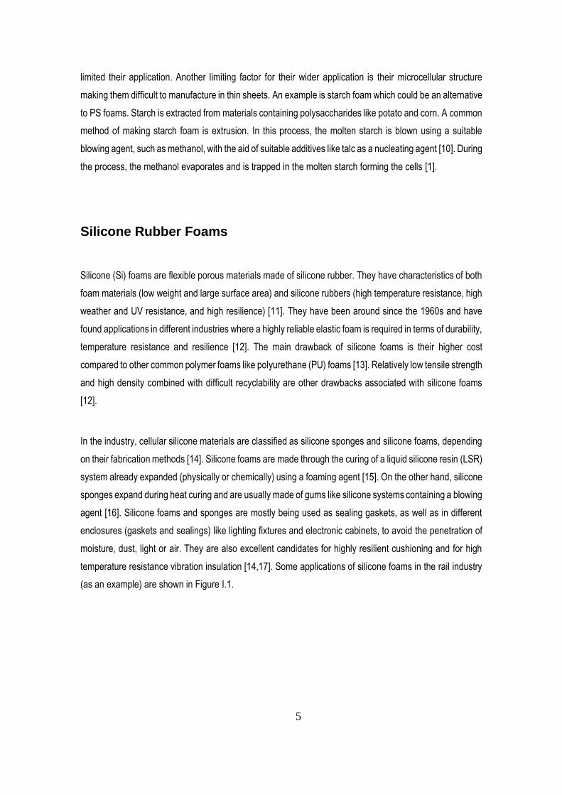
temperature resistance vibration insulation [14,17]. Some applications of silicone foams in the rail industry
(as an example) are shown in Figure I.1.
6
Figure I.1 Some examples of silicone foams application in the rail industry [18].
Statement of the Problem
The foaming method and process conditions highly affect the cell density, cell size, cell shape, cell
distribution quality, and consequently the mechanical properties [19]. This is especially true for blown
polymer foams [8]. For syntactic foams, which are expanded using hollow particles, in addition to the effects
of the cell geometry, their compressive properties highly depend on the properties of the embedded hollow
particles [20]. This is related to the fact that under compression, these hollow particles take a significant part
in the load bearing (mechanical contribution) and this highly affects the foam properties like the compression
modulus [20].
Recently, a new class of rubber foams was developed by the research group of Prof. Rodrigue at Université
Laval [11], which are made in a similar way as syntactic foams, but the solid particles (expandable beads)
added to control the foam structure have no effect on the foam’s compressive properties. The fabrication
method of these novel foams includes dispersing shrinkable lightweight particles (like expanded polystyrene
beads) as the foaming agent into a reactive liquid rubber (like silicone rubber). After solidifying the mixture,
7
the solid particles (bead skin) are shrunk leaving only voids in the solidified rubber resin. Although these
particles remain in the foam, they have no effect on the foam’s compressive modulus due to their small size.
The effects of cell size on the mechanical properties of these newly developed rubber foams have not been
studied yet. Therefore, this research project was conducted to partially fill this gap. In this research, the
effect of cell size on the compressive properties of silicone rubber foams with spherical closed cells was
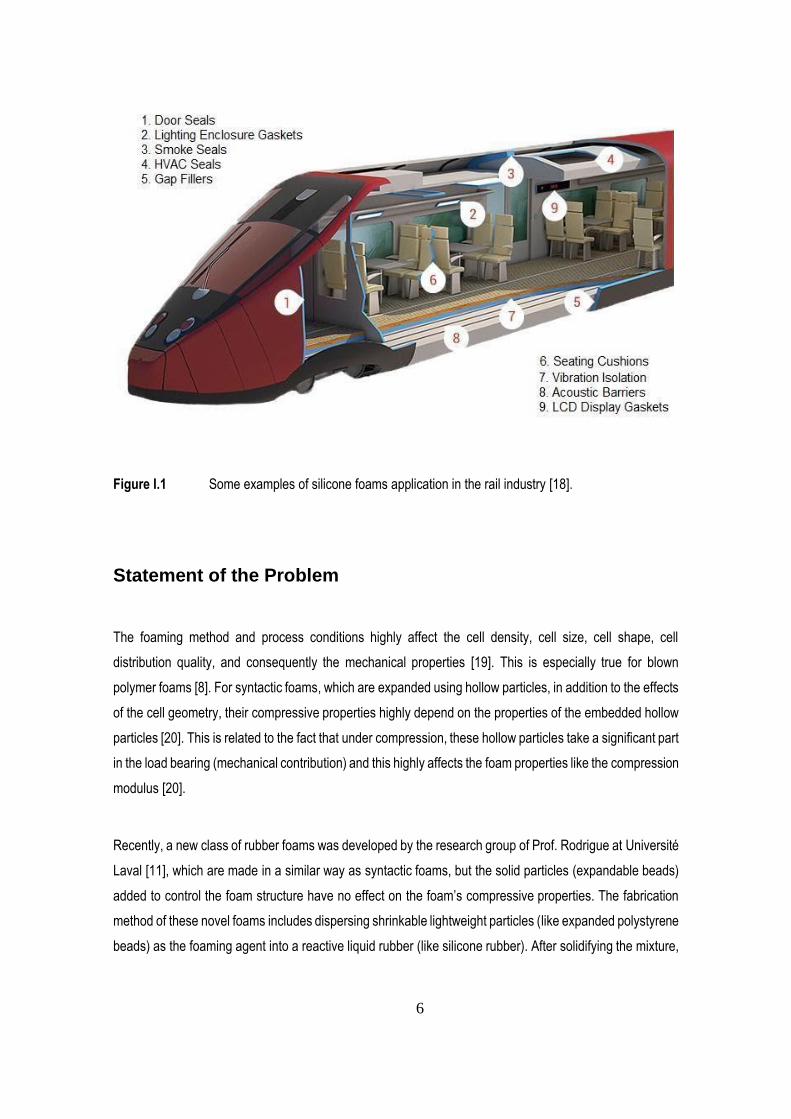
studied within the scopes given in the next section (scope of the research). Actually, this research answered
the question illustrated in Figure I.2: among the three rubber foams having the same matrix composition but
different cell sizes, which one gives the lowest compressive properties to weight ratio and which one gives
the highest ratio, when they are slowly compressed?
Figure I.2 Schematic representation of three rubber foams with different cell sizes subjected to
quasi-static compressive loads.
8
Objectives of the Study
The main objective of this research is to determine the effect of cell size on the quasi-static compressive
properties of silicone foams with spherical closed cells. To achieve this objective, the following sub-objectives
are required:
i. To fabricate three different closed cell silicone foams with different cell sizes.
ii. To measure the quasi-static compressive properties of the foams.
iii. To compare the samples and analyse the results based on different cell size to
conclude on the quasi-static compressive properties of the foams.
Scope of the Study
This research experimentally investigates the effect of cell size on the compressive properties of rubber
foams with spherical closed cells. In this research, three different rubber foams with different cell sizes (1
mm, 1.5 mm and 2 mm in diameter) were fabricated using compression molding. The rubber foams were
made using a standard liquid silicone rubber resin system. Expanded polystyrene beads were used to form
the spherical closed cells within the silicone rubber matrix. The test specimens were prepared and tested in
a compression test rig with a quasi-static rate (0.015 s-1). The compressive properties including compressive
modulus and compressive strength were obtained from the stress-strain curve.
Significance of the Study
Foam morphology (cell geometry and density) is one of the main parameters significantly affecting the
compressive properties of the foam. Silicone foams are mostly used in application under compression,
therefore investigating their compressive properties is important. Since the preparation of silicone foams is
complex, the control of the cellular microstructure to achieve a uniform morphology is difficult [7]. But this
research uses a different method (EPS beads) giving a uniform structure allowing a more accurate control

9
of the final cellular structure. The results and finding of this research are useful for predicting the deformation
behavior of closed cell rubber foams subjected to compression loads.
10
Chapter 1 Literature Review
1.1 Introduction
This chapter gives an overview of the compression behavior of polymer foams with a focus on silicone rubber
foaming chemistry. Then, a discussion on recent studies related to silicone foam developments is presented
with specific investigations on their mechanical properties.
1.2 Compression Behavior of Polymer Foams
Foam materials have physical and mechanical properties which are measured by methods similar to those
used for unfoamed materials. But several parameters are affecting the mechanical behavior of a polymer
foam including cell density, cell size and cell morphology, as well as the composition of the matrix [21].
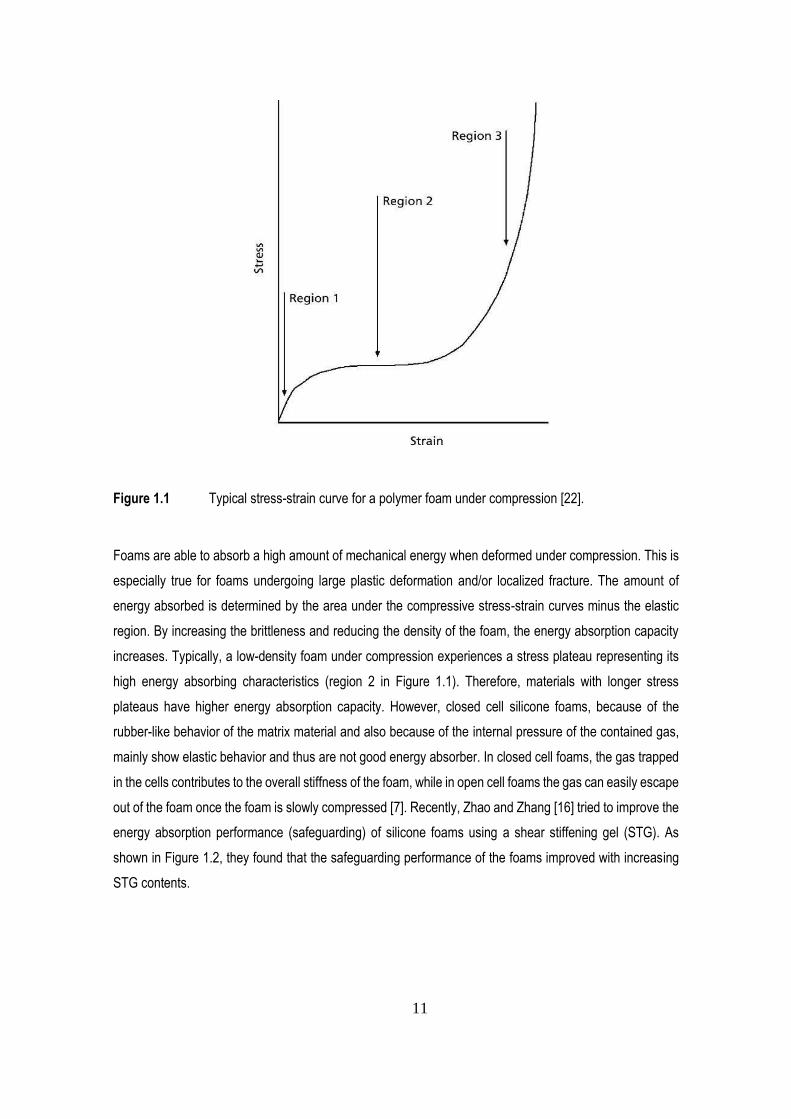
However, all foams, including polymer foams, show a strain-stress curve similar to the curve shown in Figure
1.1 under compression [22]. This curve can be divided into three different regions: elastic region (small
deformation), collapse plateau region (intermediate deformation) and densification region (high
deformation). Under compression, polymer foams, including silicone foams, first undergo elastic deformation
which is controlled by the cell wall bending or stretching. In open cell foams, the cell wall bends under
compressive load, while the cell wall stretches under the internal pressure of the contained gas in closed
cell foams [22]. After the elastic deformation, the foam continues to undergo a large compressive
deformation without significant stress increase in the collapse plateau region. In this step, flexible foams
deform as their cells collapse due to cell wall buckling under the compressive stress, while brittle foams
experience cell wall fracture and cell crushing leading to plastic deformation [23]. Once all the cells are
mostly collapsed, densification starts to occur. In this step, the opposing cell walls come into contact in every
cell and by imposing more deformation the stress substantially increases associated the matrix
compressibility, resulting in a sharp transition (higher slope) in the stress-strain curve [22].
11
Figure 1.1 Typical stress-strain curve for a polymer foam under compression [22].
Foams are able to absorb a high amount of mechanical energy when deformed under compression. This is
especially true for foams undergoing large plastic deformation and/or localized fracture. The amount of
energy absorbed is determined by the area under the compressive stress-strain curves minus the elastic
region. By increasing the brittleness and reducing the density of the foam, the energy absorption capacity
increases. Typically, a low-density foam under compression experiences a stress plateau representing its
high energy absorbing characteristics (region 2 in Figure 1.1). Therefore, materials with longer stress
plateaus have higher energy absorption capacity. However, closed cell silicone foams, because of the
rubber-like behavior of the matrix material and also because of the internal pressure of the contained gas,
mainly show elastic behavior and thus are not good energy absorber. In closed cell foams, the gas trapped
in the cells contributes to the overall stiffness of the foam, while in open cell foams the gas can easily escape
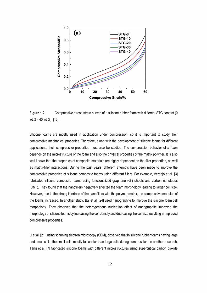
out of the foam once the foam is slowly compressed [7]. Recently, Zhao and Zhang [16] tried to improve the
energy absorption performance (safeguarding) of silicone foams using a shear stiffening gel (STG). As
shown in Figure 1.2, they found that the safeguarding performance of the foams improved with increasing
STG contents.
12
Figure 1.2 Compressive stress-strain curves of a silicone rubber foam with different STG content (0
wt.% - 40 wt.%) [16].
Silicone foams are mostly used in application under compression, so it is important to study their
compressive mechanical properties. Therefore, along with the development of silicone foams for different
applications, their compressive properties must also be studied. The compression behavior of a foam
depends on the microstructure of the foam and also the physical properties of the matrix polymer. It is also
well known that the properties of composite materials are highly dependent on the filler properties, as well
as matrix-filler interactions. During the past years, different attempts have been made to improve the
compressive properties of silicone composite foams using different fillers. For example, Verdejo et al. [3]
fabricated silicone composite foams using functionalized graphene (Gr) sheets and carbon nanotubes
(CNT). They found that the nanofillers negatively affected the foam morphology leading to larger cell size.
However, due to the strong interface of the nanofillers with the polymer matrix, the compressive modulus of
the foams increased. In another study, Bai et al. [24] used nanographite to improve the silicone foam cell
morphology. They observed that the heterogeneous nucleation effect of nanographite improved the
morphology of silicone foams by increasing the cell density and decreasing the cell size resulting in improved
compressive properties.
Li et al. [21], using scanning electron microscopy (SEM), observed that in silicone rubber foams having large
and small cells, the small cells mostly fail earlier than large cells during compression. In another research,
Tang et al. [7] fabricated silicone foams with different microstructures using supercritical carbon dioxide
13
(sCO2) and studied their compressive properties. They concluded that for closed cell foams under
compression, the stress increases with increasing strain due to an additional contribution of the gas
compression inside the cells.
1.3 Silicone Rubber Foaming Chemistry
Silicone rubber is a thermoset elastomer composed of a silicone polymer [25]. Silicone itself is a synthetic
polymer made up of silicon, oxygen, carbon and hydrogen atoms [12]. Silicon and oxygen atoms construct
the backbone of silicone, while organic side groups containing carbon and hydrogen (methyl, ethyl, etc.) are
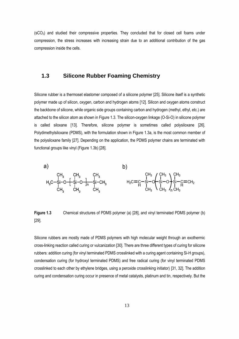
attached to the silicon atom as shown in Figure 1.3. The silicon-oxygen linkage (O-Si-O) in silicone polymer
is called siloxane [13]. Therefore, silicone polymer is sometimes called polysiloxane [26].
Polydimethylsiloxane (PDMS), with the formulation shown in Figure 1.3a, is the most common member of
the polysiloxane family [27]. Depending on the application, the PDMS polymer chains are terminated with
functional groups like vinyl (Figure 1.3b) [28].
Figure 1.3 Chemical structures of PDMS polymer (a) [28], and vinyl terminated PDMS polymer (b)
[29].
Silicone rubbers are mostly made of PDMS polymers with high molecular weight through an exothermic
cross-linking reaction called curing or vulcanization [30]. There are three different types of curing for silicone
rubbers: addition curing (for vinyl terminated PDMS crosslinked with a curing agent containing Si-H groups),
condensation curing (for hydroxyl terminated PDMS) and free radical curing (for vinyl terminated PDMS
crosslinked to each other by ethylene bridges, using a peroxide crosslinking initiator) [31, 32]. The addition
curing and condensation curing occur in presence of metal catalysts, platinum and tin, respectively. But the
14
free radical cured rubbers do not require a catalyst and the reaction initiates using a peroxide compound
[13].
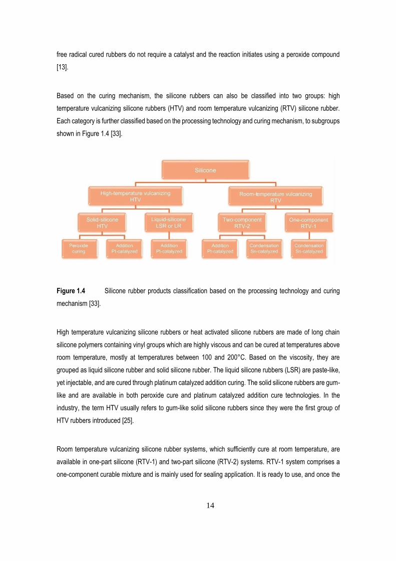
Based on the curing mechanism, the silicone rubbers can also be classified into two groups: high
temperature vulcanizing silicone rubbers (HTV) and room temperature vulcanizing (RTV) silicone rubber.
Each category is further classified based on the processing technology and curing mechanism, to subgroups
shown in Figure 1.4 [33].
Figure 1.4 Silicone rubber products classification based on the processing technology and curing
mechanism [33].
High temperature vulcanizing silicone rubbers or heat activated silicone rubbers are made of long chain
silicone polymers containing vinyl groups which are highly viscous and can be cured at temperatures above
room temperature, mostly at temperatures between 100 and 200°C. Based on the viscosity, they are
grouped as liquid silicone rubber and solid silicone rubber. The liquid silicone rubbers (LSR) are paste-like,
yet injectable, and are cured through platinum catalyzed addition curing. The solid silicone rubbers are gum-
like and are available in both peroxide cure and platinum catalyzed addition cure technologies. In the
industry, the term HTV usually refers to gum-like solid silicone rubbers since they were the first group of
HTV rubbers introduced [25].
Room temperature vulcanizing silicone rubber systems, which sufficiently cure at room temperature, are
available in one-part silicone (RTV-1) and two-part silicone (RTV-2) systems. RTV-1 system comprises a
one-component curable mixture and is mainly used for sealing application. It is ready to use, and once the
15
paste-like mixture is out of the package the curing process starts using the air moisture. The RTV-1 silicone
systems are condensation cure and mostly composed of hydroxyl terminated silicone polymer, reinforcing
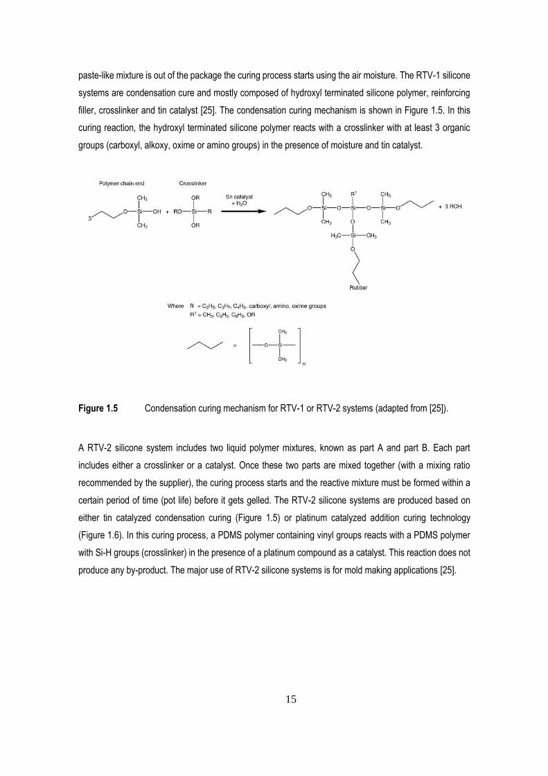
filler, crosslinker and tin catalyst [25]. The condensation curing mechanism is shown in Figure 1.5. In this
curing reaction, the hydroxyl terminated silicone polymer reacts with a crosslinker with at least 3 organic
groups (carboxyl, alkoxy, oxime or amino groups) in the presence of moisture and tin catalyst.
Figure 1.5 Condensation curing mechanism for RTV-1 or RTV-2 systems (adapted from [25]).
A RTV-2 silicone system includes two liquid polymer mixtures, known as part A and part B. Each part
includes either a crosslinker or a catalyst. Once these two parts are mixed together (with a mixing ratio
recommended by the supplier), the curing process starts and the reactive mixture must be formed within a
certain period of time (pot life) before it gets gelled. The RTV-2 silicone systems are produced based on
either tin catalyzed condensation curing (Figure 1.5) or platinum catalyzed addition curing technology
(Figure 1.6). In this curing process, a PDMS polymer containing vinyl groups reacts with a PDMS polymer
with Si-H groups (crosslinker) in the presence of a platinum compound as a catalyst. This reaction does not
produce any by-product. The major use of RTV-2 silicone systems is for mold making applications [25].
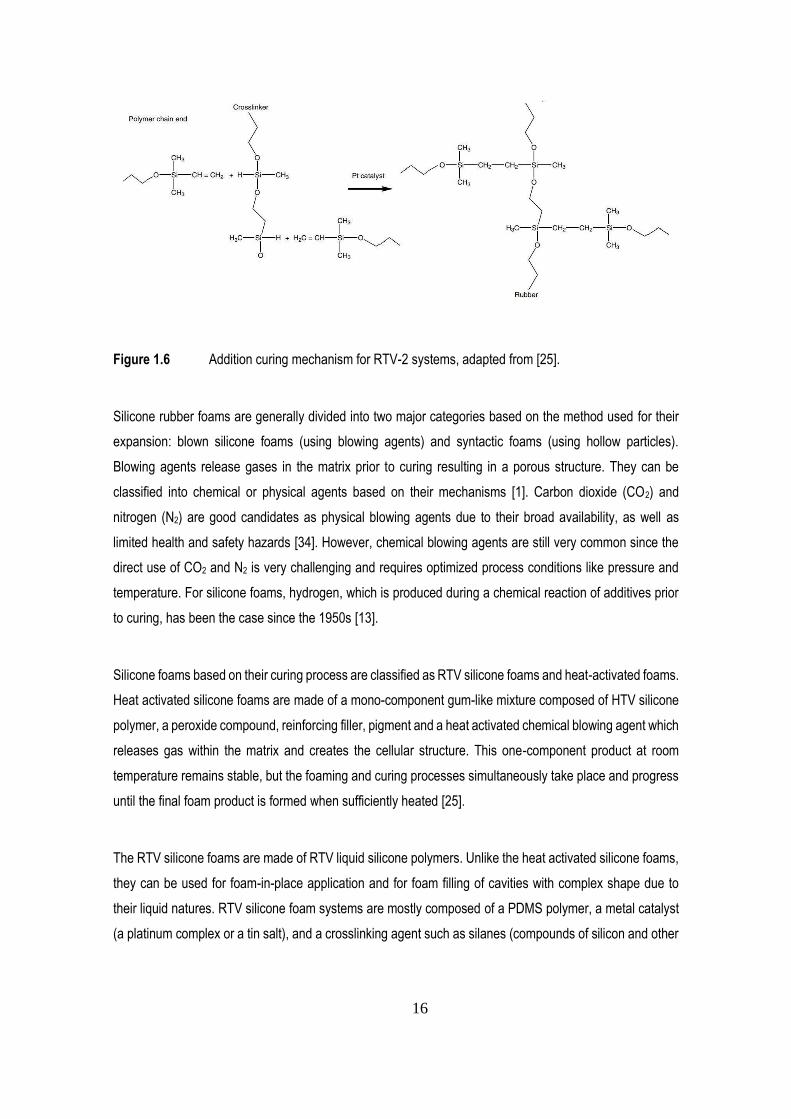
16
Figure 1.6 Addition curing mechanism for RTV-2 systems, adapted from [25].
Silicone rubber foams are generally divided into two major categories based on the method used for their
expansion: blown silicone foams (using blowing agents) and syntactic foams (using hollow particles).
Blowing agents release gases in the matrix prior to curing resulting in a porous structure. They can be
classified into chemical or physical agents based on their mechanisms [1]. Carbon dioxide (CO2) and
nitrogen (N2) are good candidates as physical blowing agents due to their broad availability, as well as
limited health and safety hazards [34]. However, chemical blowing agents are still very common since the
direct use of CO2 and N2 is very challenging and requires optimized process conditions like pressure and
temperature. For silicone foams, hydrogen, which is produced during a chemical reaction of additives prior
to curing, has been the case since the 1950s [13].
Silicone foams based on their curing process are classified as RTV silicone foams and heat-activated foams.
Heat activated silicone foams are made of a mono-component gum-like mixture composed of HTV silicone
polymer, a peroxide compound, reinforcing filler, pigment and a heat activated chemical blowing agent which
releases gas within the matrix and creates the cellular structure. This one-component product at room
temperature remains stable, but the foaming and curing processes simultaneously take place and progress
until the final foam product is formed when sufficiently heated [25].
The RTV silicone foams are made of RTV liquid silicone polymers. Unlike the heat activated silicone foams,
they can be used for foam-in-place application and for foam filling of cavities with complex shape due to
their liquid natures. RTV silicone foam systems are mostly composed of a PDMS polymer, a metal catalyst
(a platinum complex or a tin salt), and a crosslinking agent such as silanes (compounds of silicon and other
17
atoms), or siloxanes containing a functional group of (hydroxyl, alkoxyl, acetoxyl or hydrogen atoms) [35].
RTV silicone foam systems are supplied as two-part products, with a specific mixing ratio. When these two
parts are mixed together, the cure reaction and gas generation processes simultaneously take place and
progress without requiring any heat application. In this case, a cured cellular rubber product is achieved
usually within a few minutes [25]. During the foam preparation, the silicone chains are crosslinked in the
presence of a platinum or tin catalyst [36, 37]. They react in parallel with a suitable additive like alcohol or
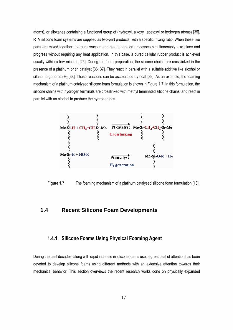
silanol to generate H2 [38]. These reactions can be accelerated by heat [39]. As an example, the foaming
mechanism of a platinum catalyzed silicone foam formulation is shown in Figure 1.7. In this formulation, the
silicone chains with hydrogen terminals are crosslinked with methyl terminated silicone chains, and react in
parallel with an alcohol to produce the hydrogen gas.
Figure 1.7 The foaming mechanism of a platinum catalysed silicone foam formulation [13].
1.4 Recent Silicone Foam Developments
1.4.1 Silicone Foams Using Physical Foaming Agent
During the past decades, along with rapid increase in silicone foams use, a great deal of attention has been
devoted to develop silicone foams using different methods with an extensive attention towards their
mechanical behavior. This section overviews the recent research works done on physically expanded
18
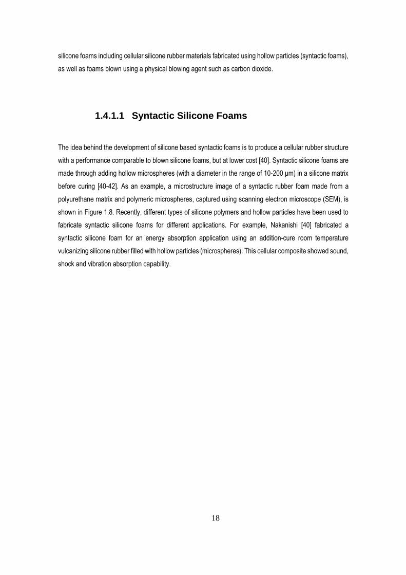
silicone foams including cellular silicone rubber materials fabricated using hollow particles (syntactic foams),
as well as foams blown using a physical blowing agent such as carbon dioxide.
1.4.1.1 Syntactic Silicone Foams
The idea behind the development of silicone based syntactic foams is to produce a cellular rubber structure
with a performance comparable to blown silicone foams, but at lower cost [40]. Syntactic silicone foams are
made through adding hollow microspheres (with a diameter in the range of 10-200 μm) in a silicone matrix
before curing [40-42]. As an example, a microstructure image of a syntactic rubber foam made from a
polyurethane matrix and polymeric microspheres, captured using scanning electron microscope (SEM), is
shown in Figure 1.8. Recently, different types of silicone polymers and hollow particles have been used to
fabricate syntactic silicone foams for different applications. For example, Nakanishi [40] fabricated a
syntactic silicone foam for an energy absorption application using an addition-cure room temperature
vulcanizing silicone rubber filled with hollow particles (microspheres). This cellular composite showed sound,
shock and vibration absorption capability.
19
Figure 1.8 SEM image of a syntactic rubber foam made from a polyurethane matrix and polymeric
microsphere [41].
In another study, Kenig et al. [42] fabricated a syntactic foam using hollow silica microspheres with an
average diameter of 100 microns and a powdered condensation curing silicone-based resin. They compared
the mechanical performance of this cellular composite with another composite made of the same matrix
material (with same volumetric resin content), but filled with solid glass beads. They found that the
compressive strength of the hollow sphere filled composites (syntactic foams) was higher than the one filled
with solid beads. Kessler et al. [43] studied the compressive properties of syntactic silicone foams filled with
polymeric calcium carbonate coated hollow spheres. They investigated the effects of microspheres
concentration on the compressive modulus and found that increasing the microspheres volume fraction from
10% to 30% decreased by 50% the compressive modulus due to a higher volume of compressible gas within
the foam.
Yazici et al. [37] fabricated syntactic silicone foams with different microsphere contents (10, 20 and 30%
wt.) using a liquid addition-cure silicone resin system and two different types of glass microspheres. They
tested the foams under quasi-static compression load and observed that by increasing the microspheres
content the plateau stress region of the stress-strain curve extended, thus the energy absorption capacity
20
of the foams improved. Schumann et al. [44] fabricated different types of syntactic silicone foams using two
different high temperature vulcanizing silicone rubber systems: a liquid silicone rubber system and a solid
silicone system. They filled the silicone rubber systems with ceramic and hollow glass microspheres of
different sizes and tested their tensile properties. They found that all the foams showed lower elongation at
break by increasing the microspheres content. However, the cell size did not significantly affect the tensile
properties. Comparing the ceramic microspheres to the glass ones, the former showed lower tensile
strength.
In another research, Alex et al. [45] fabricated syntactic foams using ceramic and glass microspheres in an
addition-curing room temperature vulcanizing liquid silicone resin system to investigate the physical
properties of the foams including tensile properties. They concluded that adding 5% wt. of microsphere
decreased the specific tensile strength, but increasing the microsphere content to 20% significantly
increased the specific strength due to the low density of the microspheres and also better interfacial bonding
with the matrix.
1.4.1.2 Silicone Foams Using Physical Blowing Agent
In recent years, many efforts have been made in developing foaming methods without causing significant
negative effects on the mechanical properties of the materials [46]. Some attempts have been made to foam
different silicone rubbers using a physical blowing agent. Recently, some literature reported on the
successful preparation of silicone foams using supercritical carbon dioxide (sCO2) as a physical blowing
agent. The sCO2 is a fluid state of CO2 where it is held above its critical pressure and critical temperature to
avoid phase change [47]. The solubility of sCO2 in polymers is higher than carbon dioxide in its gas state
[48]. However, foaming silicone rubber using sCO2 is very challenging, and in most silicone foams, fabricated
using this technology, some surface defects have been observed [49]. There are many parameters and
process conditions to be optimized and controlled in sCO2 foaming of silicone rubbers such as composition,
rheology and curing kinetics of the matrix, as well as temperature and pressure.
For instance, Song et al. [23] attempted to foam a pre-cured peroxide cure solid rubber resin system using
sCO2 foaming technology. They concluded that the sCO2 technology can be used to foam cross-linked
silicone rubbers. However, the pre-curing time is a key factor in the foaming process and affects the foam
morphology. Lee et al. [48] fabricated silicone rubber foams with a cell size of 12 microns using a pre-cured
21
high temperature vulcanizing liquid silicone resin system and sCO2. They investigated the effect of curing
degree prior to foaming on the final cell size of silicone rubber foams. They observed that the cell sizes
significantly decreased and the foam density increased by increasing the cure degree. Liao et al. [50]
fabricated silicone foams using a peroxide cure solid rubber resin system and sCO2. They found that the
composition and viscoelastic properties of the silicone rubber played a significant role in the sCO2 foaming
process. Yang et al. [51] fabricated different silicone foams using high temperature vulcanizing solid silicone
rubber and sCO2. They tried to improve the cell structure and decrease the cell size by optimizing the
process conditions. They achieved silicone foams with cell sizes smaller than 10 μm. A series of silicone
rubber foams were fabricated by Xiang et al. [8] using sCO2 to investigate the effect of silica as a reinforcing
agent on the cellular morphology and nucleation of silicone rubber composites. Their results showed that
silica can act as a nucleation agent in silicone rubber composite foams controlling the cell size and density.
1.4.2 Silicone foams using chemical foaming agents
Another method for the fabrication of silicone foams is to produce gas pockets within a silicone matrix using
a chemical blowing agent (CBA). This is usually done through blending a silicone resin rubber resin system
with a chemical blowing agent prior to curing. However, this method requires an optimized formulation to
obtain a silicone foam with an acceptable morphology. This is because during the foaming process, there is
another process taking place which is the crosslinking of the silicone polymer`s chains. These two processes
must be well balanced to obtain a foam with the desired density and good properties [13]. Chemical blowing
agents are usually directly added into the matrix. For silicone rubber foams, the chemical blowing agent has
to be dispersible in the selected silicone resin system prior to foaming, and must also be compatible with
the related catalyst. Otherwise, the CBA interferes with the crosslinking reaction and inhibits the curing
completion. Additionally, the CBA must be able to decompose close to an optimal temperature to produce
the gas [52].
During the past decades, different silicone foams have been successfully developed using CBA and
characterized for their properties. For example, Park [53] used AIBN (2,2-azobisisobutyronitrile) to foam a
peroxide cure high temperature vulcanizing solid silicone resin system. The AIBN blowing agent, when
sufficiently heated, decomposed and released nitrogen. The peroxide concentration in the silicone was
changed to investigate the effect of the curing level on the morphology and mechanical properties of the
foams. He observed that by increasing the peroxide concentration, the hardness, tensile strength and foam
22
density increased, but the cell size decreased. This is because an increase in the peroxide concentration
increases the crosslinking density and the silicone viscosity, therefore the cells were not able to grow. In
another study, Gao et al. [54] used (N,N-dinitrosopentametgylenetetramine) as the blowing agent to foam a
high temperature vulcanizing solid silicone resin system reinforced with nano-silica.
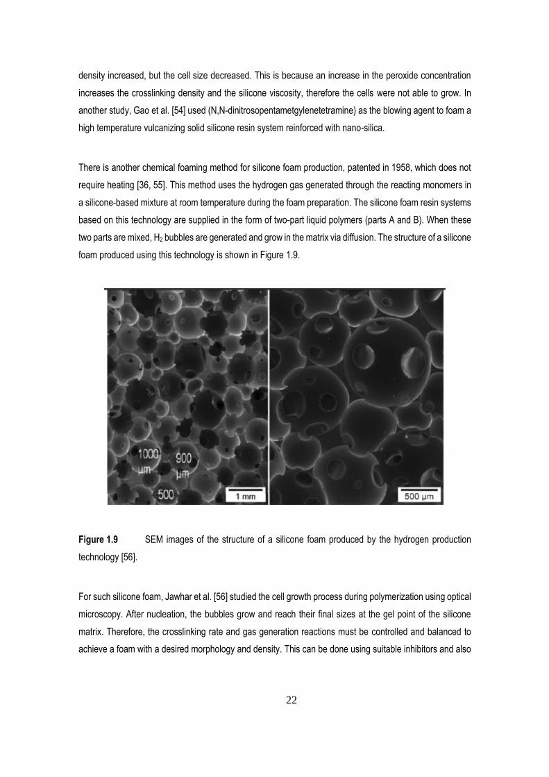
There is another chemical foaming method for silicone foam production, patented in 1958, which does not
require heating [36, 55]. This method uses the hydrogen gas generated through the reacting monomers in
a silicone-based mixture at room temperature during the foam preparation. The silicone foam resin systems
based on this technology are supplied in the form of two-part liquid polymers (parts A and B). When these
two parts are mixed, H2 bubbles are generated and grow in the matrix via diffusion. The structure of a silicone
foam produced using this technology is shown in Figure 1.9.
Figure 1.9 SEM images of the structure of a silicone foam produced by the hydrogen production
technology [56].
For such silicone foam, Jawhar et al. [56] studied the cell growth process during polymerization using optical
microscopy. After nucleation, the bubbles grow and reach their final sizes at the gel point of the silicone
matrix. Therefore, the crosslinking rate and gas generation reactions must be controlled and balanced to
achieve a foam with a desired morphology and density. This can be done using suitable inhibitors and also
23
by adjusting the concentration of catalysts, inhibitors and reinforcing/modifying fillers in the formulation [56].
Most of the recent silicone foam formulations have been based on the addition of fillers to improve or modify
the foam properties such as hardness, tensile strength, thermal/electrical conductivity and fire resistance
[57, 58]. But filler addition directly affects the rheology of the reactive mixture and thus the foam morphology
and properties. Fillers also prevent the proper development of the voids and negatively affect the shape of
the pores [56].
Verdejo et al. [57] fabricated room temperature vulcanized silicone foams reinforced with graphene sheets
and carbon nanotubes to investigate the fillers effect on the morphology and properties including mechanical
properties. They found that the foam morphologies were negatively affected by the fillers resulting in foams
with thicker cell walls associated to increased viscosity. Compared to a silicone foam made from the pristine
resin system, the compression modulus of the foams increased with filler addition. Very recently, Liu et al.
[58] added liquid fillers, including silicone oil, to the formulation of a room vulcanizing silicone foam system
to improve the electrical properties for sensor application. They found that adding liquid fillers decreased the
compression modulus of the foams.
1.5 Summary of Literature Review
In this chapter an overview of the compression behavior of polymer foams and silicone rubber foaming
chemistry was given. Recent studies on silicone foam developments were reported and discussed with a
focus on their mechanical properties.
Silicone foams have the combined properties of a foam and silicone which became a solution for tough
engineering challenges where stability against weathering, heat and UV is important. Several parameters,
including processing parameters and rheological properties of the formulation, affect the silicone foam
properties. As discussed, the method used for foaming has a direct effect on the cell shape and size which
will affect the mechanical properties of the foam including compression properties. Silicone foams are
produced through expanding a silicone resin system before/simultaneously with curing using a physical or
chemical process. Chemical foaming is the most common industrial method for silicone foam production. This
includes forming gas pockets within a silicone rubber resin system using gas produced through the
decomposition of a blowing agent or produced during a chemical reaction between the silicone monomers
and some additives. Silicone foaming based on the hydrogen production technology is limited to liquid rubber
24
silicone resin systems. Furthermore, there is some safety issues related to hydrogen in some environments
which is a concern. In physical foaming, a large number of gas pockets is introduced into a silicone rubber
matrix prior to curing. This can be done by the direct introduction of a gas as a blowing agent or by embedding
hollow particles.
Processing of silicone foams using a chemical or physical blowing agent is difficult as it is very sensitive to
the process conditions. This requires a balance between the cross-linking and the cell growth kinetics. It
becomes even more complex in the case of high filler content. On the other hand, processing syntactic foams
is very user friendly and does not require heat application. It also allows a better control of the cell size and
density, thus a direct control on the mechanical properties. However, the compressive properties of syntactic
foams highly depend on the properties of the embedded hollow particles as these particles take a significant
part in load bearing applications. Therefore, there is a need for an improved foaming method offering the
convenience and consistency of the syntactic foaming method without influencing the silicone matrix
composition.
Foam morphology (cell size, geometry and density) is one of the main parameters affecting the compressive
properties of the foams. Silicone foams are mostly used in application under compression, therefore
investigating their compressive properties is important, especially for material selection purposes. Although
several researches are available for silicone rubber foams, only a few studies focused on the relationship
between the cell geometry and compressive properties of silicone foams. Also, these studies were limited to
silicone foams with non-spherical cells. This limited amount of information motivated the present research
project by focusing on silicone foams with spherical cells.
25
Chapter 2 Research Methodology
2.1 Introduction
The main purpose of this research was to experimentally investigate the effect of cell size on the
compressive properties of rubber foams with spherical closed cells. This chapter addresses the methods,
materials and equipment which were used to achieve this goal. In this research, foam samples with different
cell sizes were fabricated and then tested for their compressive behavior. The results were then compared
to each other to find the effect of cell size on the compression properties
2.2 Fabrication of the Silicone Foam Samples
In this project, three rubber foams with different cell sizes were fabricated using compression molding. The
rubber foams were made using the materials and procedure reported below.
2.2.1 Materials
A pourable silicone rubber system, vulcanizing at room temperature and offering a reasonable pot life
(working time), was used as the matrix material. In our case, ELASTOSIL® M 4370 (from Wacker) was
selected. This silicone rubber includes two parts: part A and part B. At room temperature (23oC), part A has
a viscosity of 10000 mPa.s, a density of 1.5 g/cm3 and mainly contains polydimethylsiloxane (vinyl
terminated) and iron oxide. Part B has a viscosity of 350 mPa.s, a density of 0.97 g/cm3 and contains
polymethyl hydrogen siloxane and polydimethylsiloxane (vinyl terminated). This silicone resin system cures
through an addition-cure reaction using platinum catalyst which is already included into part A. The pot-life
of this silicone system is about 80 min at 23°C.
26
To form the spherical closed cells within the silicone rubber matrix, commercially available expandable
polystyrene (EPS) beads with a bulk density of about 20 kg/m3 and diameters ranging from 1 mm to 2 mm
were prepared and used. The beads were received from Squishy Deluxe company (China) in a pillow
package. The beads were then sieved and grouped in three categories based on their size: 1 mm, 1.5 mm
and 2 mm in diameter. Then, the EPS beads were washed using ethanol (95% purity, supplied by GreenField
Specialty Alcohols Inc.) to remove any possible contamination on their surfaces as this contamination could
negatively affect the catalyst performance, inhibit the curing reaction, as well as the interactions (adhesion)
with the matrix.
2.2.2 Procedure
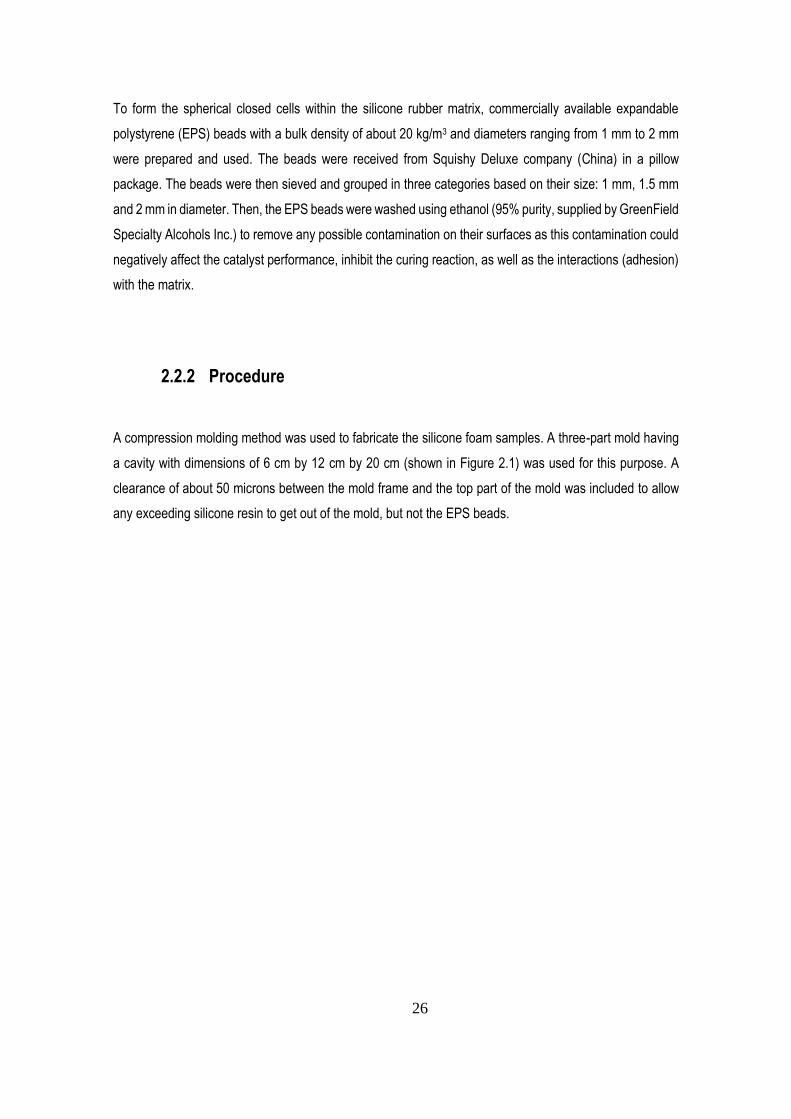
A compression molding method was used to fabricate the silicone foam samples. A three-part mold having
a cavity with dimensions of 6 cm by 12 cm by 20 cm (shown in Figure 2.1) was used for this purpose. A
clearance of about 50 microns between the mold frame and the top part of the mold was included to allow
any exceeding silicone resin to get out of the mold, but not the EPS beads.
27
Figure 2.1 The three-part mold used for foam sample fabrication.
Foam samples with a thickness of 2 cm and a surface of 12 cm by 20 cm (volume of 480 cm3) were fabricated
through the following sequences.
Firstly, 2 cm of the cavity height was filled with a sufficient number of EPS beads. The next step was to add
the reactive silicone resin mixture with an amount of about 60% of the specimen volume into the mold. This
value was obtained from previous experiments. Therefore, about 290 cm3 of silicone resin was required
which was prepared as follow: Based on the mixing ratio recommended by the supplier (6:1 by volume),
about 270 cm3 of parts A with 45 cm3 of part B of the silicone resin system were mixed together in a
graduated plastic beaker using a dual hand mixer to prepare 315 cm3 of the reactive silicone resin. About
290 cm3 of the prepared resin was then poured in the mold and manually mixed with the beads using a stick.
Since the EPS beads are less dense than the silicone resin, they tend to move toward the surface and float
on top of the low viscosity resins, which was the case for the present research. To avoid this segregation
problem, subsequently, using the top part of the mold the height of the cavity was reduced to 2 cm. This
action applies a compression stress on the mixture and pushes the beads back into the liquid silicone while
pushing the extra amount of resin out of the mold through the mold clearance, resulting in a homogenous
beads distribution. By removing the exceeding resin, the compression stress in the mixture substantially
decreases and the flexible EPS beads recover their initial sizes and geometries. However, since the resin
is slightly viscous, the mixture remains under a low level of stress. Then, the mold was left at room
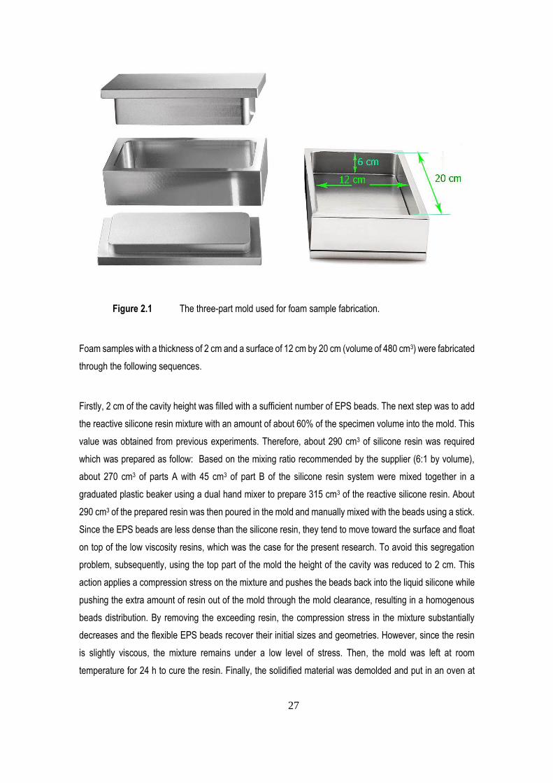
temperature for 24 h to cure the resin. Finally, the solidified material was demolded and put in an oven at
28
130oC for 1 h to shrink down the bead and to form the empty cells (voids). These conditions were also
obtained from previous experiments (preliminary tests). A schematic view of the fabrication steps is shown
in Figure 2.2.
Figure 2.2 Schematic view of the foam sample fabrication process.
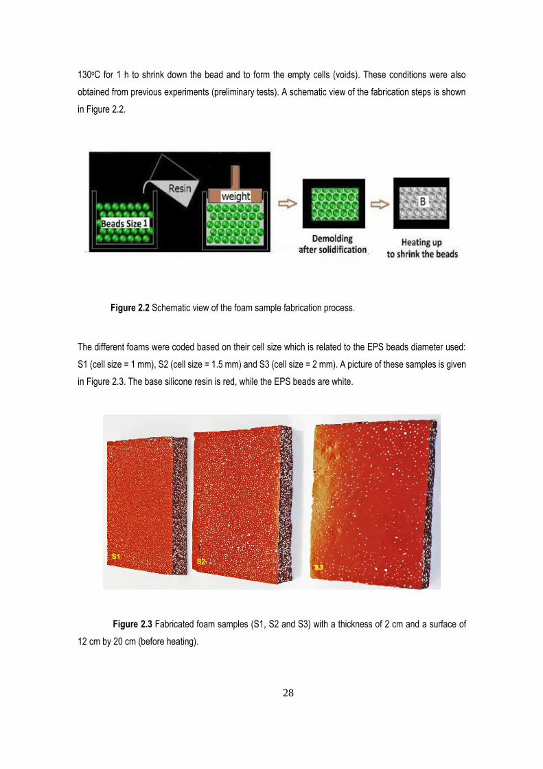
The different foams were coded based on their cell size which is related to the EPS beads diameter used:
S1 (cell size = 1 mm), S2 (cell size = 1.5 mm) and S3 (cell size = 2 mm). A picture of these samples is given
in Figure 2.3. The base silicone resin is red, while the EPS beads are white.
Figure 2.3 Fabricated foam samples (S1, S2 and S3) with a thickness of 2 cm and a surface of
12 cm by 20 cm (before heating).
29
2.3 Characterization and Data Analysis
2.3.1 Foam Density
After foam samples preparation, their bulk density was measured. The samples were weighed using a digital
scale and the mass was divided by their volume. The foam volume for each sample was obtained by
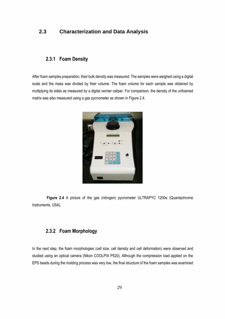
multiplying its sides as measured by a digital vernier caliper. For comparison, the density of the unfoamed
matrix was also measured using a gas pycnometer as shown in Figure 2.4.
Figure 2.4 A picture of the gas (nitrogen) pycnometer ULTRAPYC 1200e (Quantachrome
Instruments, USA).
2.3.2 Foam Morphology
In the next step, the foam morphologies (cell size, cell density and cell deformation) were observed and
studied using an optical camera (Nikon COOLPIX P520). Although the compression load applied on the
EPS beads during the molding process was very low, the final structure of the foam samples was examined
30
using the above camera to see whether or not the geometries of the cells were changed during the process.
This observation also helped to see if the cells are interconnected or not.
For each foam, the cell density (number of cells in 1 cm3 of the foam) was determined as [59]:
Cell density = (n)3/2 * (Vf /Vm) (2.1)
where Vm and Vf denote the volume of the matrix material (unfoamed) and volume of the foam respectively,
while n denotes the number of cells in an area of 1 cm by 1 cm, which can be counted without using the
microscope.
By having the density of the unfoamed matrix from the pycnometer, the value of Vm was calculated as:
Vm = (mass of the foam before heating - mass of the contained EPS beads) / density of the matrix material
(2.2)
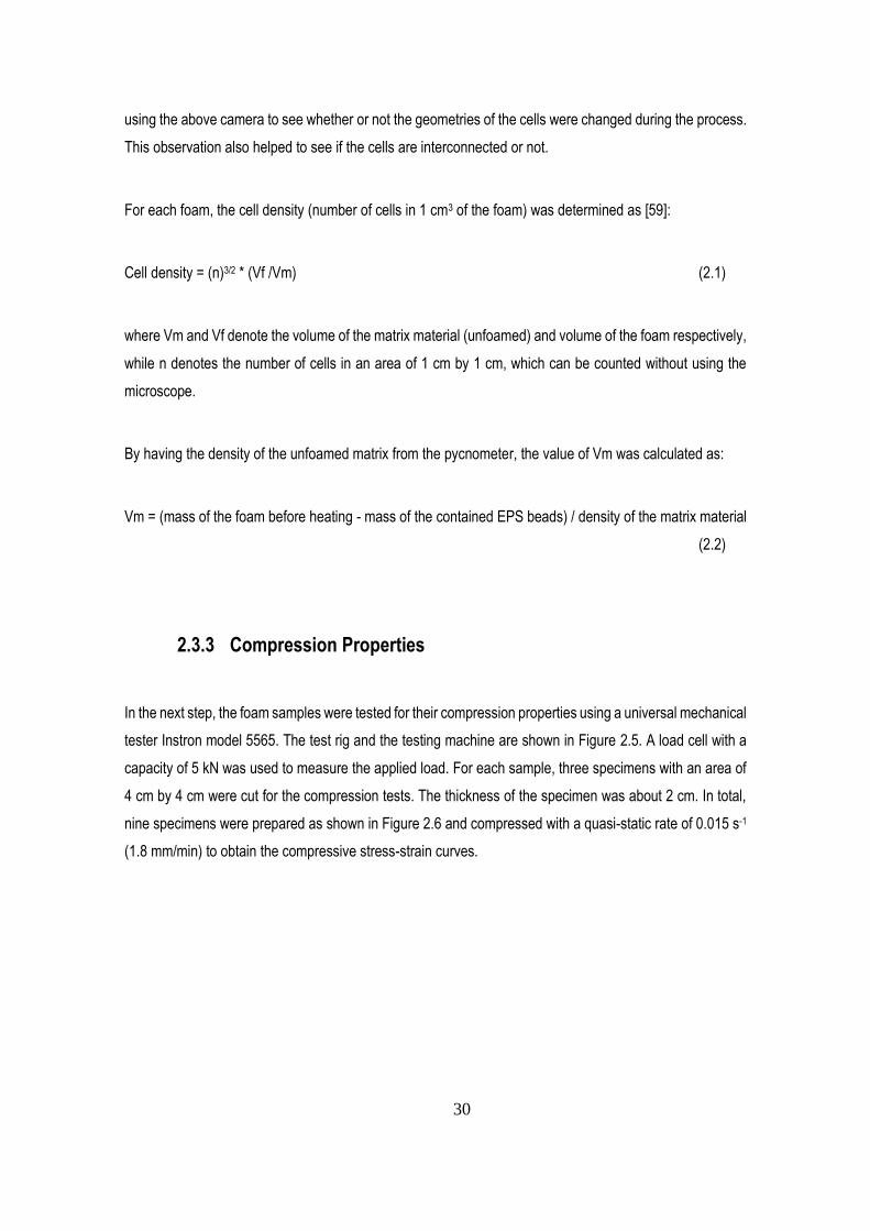
2.3.3 Compression Properties
In the next step, the foam samples were tested for their compression properties using a universal mechanical
tester Instron model 5565. The test rig and the testing machine are shown in Figure 2.5. A load cell with a
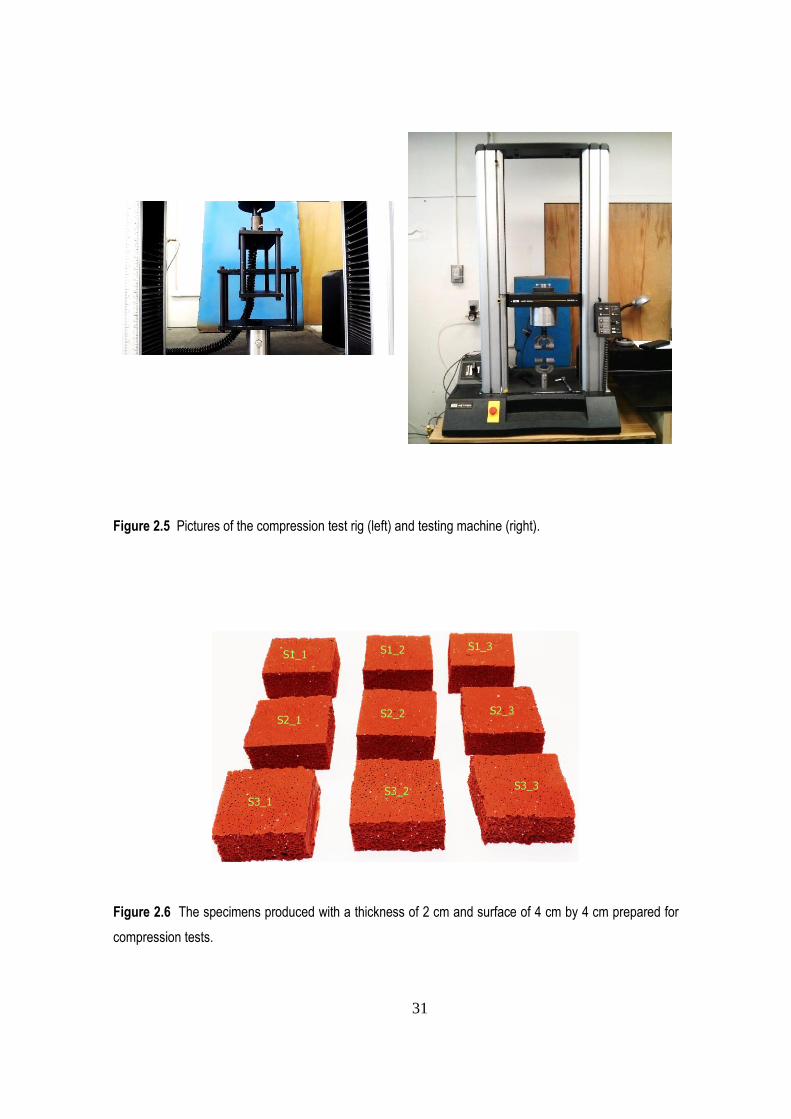
capacity of 5 kN was used to measure the applied load. For each sample, three specimens with an area of
4 cm by 4 cm were cut for the compression tests. The thickness of the specimen was about 2 cm. In total,
nine specimens were prepared as shown in Figure 2.6 and compressed with a quasi-static rate of 0.015 s-1
(1.8 mm/min) to obtain the compressive stress-strain curves.
31
Figure 2.5 Pictures of the compression test rig (left) and testing machine (right).
Figure 2.6 The specimens produced with a thickness of 2 cm and surface of 4 cm by 4 cm prepared for
compression tests.
32
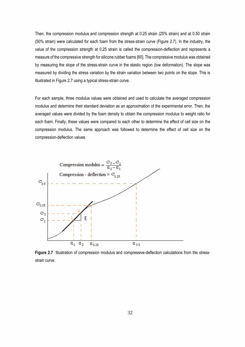
Then, the compression modulus and compression strength at 0.25 strain (25% strain) and at 0.50 strain
(50% strain) were calculated for each foam from the stress-strain curve (Figure 2.7). In the industry, the
value of the compression strength at 0.25 strain is called the compression-deflection and represents a
measure of the compressive strength for silicone rubber foams [60]. The compressive modulus was obtained
by measuring the slope of the stress-strain curve in the elastic region (low deformation). The slope was
measured by dividing the stress variation by the strain variation between two points on the slope. This is
illustrated in Figure 2.7 using a typical stress-strain curve.
For each sample, three modulus values were obtained and used to calculate the averaged compression
modulus and determine their standard deviation as an approximation of the experimental error. Then, the
averaged values were divided by the foam density to obtain the compression modulus to weight ratio for
each foam. Finally, these values were compared to each other to determine the effect of cell size on the
compression modulus. The same approach was followed to determine the effect of cell size on the
compression-deflection values.
Figure 2.7 Illustration of compression modulus and compressive-deflection calculations from the stress-
strain curve.
33
Chapter 3 RESULTS AND DISCUSSION
3.1 Introduction
This chapter presents the results and discusses the findings from the characterization on the fabricated
silicone foams including densities, morphologies and compression properties. It also presents the
relationships between the cell sizes and the compressive properties of the foams with respect to their
respective densities.
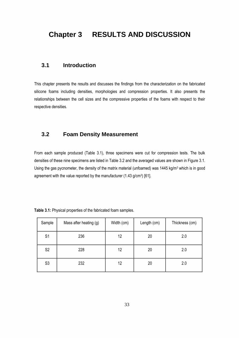
3.2 Foam Density Measurement
From each sample produced (Table 3.1), three specimens were cut for compression tests. The bulk
densities of these nine specimens are listed in Table 3.2 and the averaged values are shown in Figure 3.1.
Using the gas pycnometer, the density of the matrix material (unfoamed) was 1445 kg/m3 which is in good
agreement with the value reported by the manufacturer (1.43 g/cm3) [61].
Table 3.1: Physical properties of the fabricated foam samples.
Sample Mass after heating (g) Width (cm) Length (cm) Thickness (cm)
S1 236 12 20 2.0
S2 228 12 20 2.0
S3 232 12 20 2.0
34
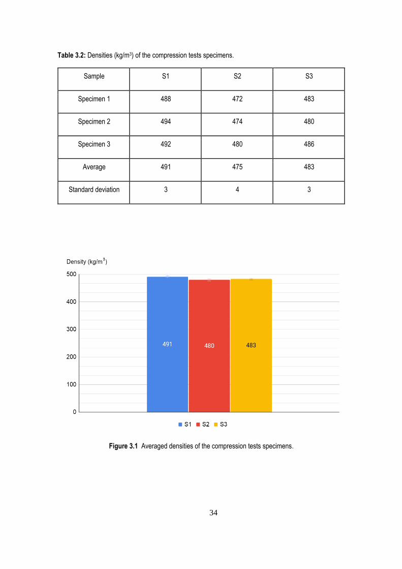
Table 3.2: Densities (kg/m3) of the compression tests specimens.
Sample S1 S2 S3
Specimen 1 488 472 483
Specimen 2 494 474 480
Specimen 3 492 480 486
Average 491 475 483
Standard deviation 3 4 3
Figure 3.1 Averaged densities of the compression tests specimens.
35
As it can be seen in Table 3.2, the standard deviations obtained for the specimens cut from samples S1, S2
and S3 are very small (less than 1%). This indicates that the samples S1, S2 and S3 are homogenous.
Table 3.2 also shows that within experimental uncertainty, there is no significant differences between the
sample densities.
3.3 Foam Morphology Analysis
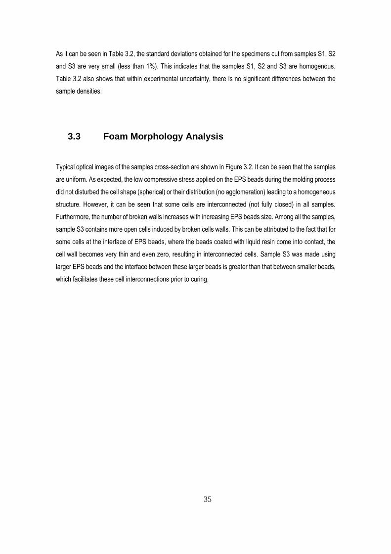
Typical optical images of the samples cross-section are shown in Figure 3.2. It can be seen that the samples
are uniform. As expected, the low compressive stress applied on the EPS beads during the molding process
did not disturbed the cell shape (spherical) or their distribution (no agglomeration) leading to a homogeneous
structure. However, it can be seen that some cells are interconnected (not fully closed) in all samples.
Furthermore, the number of broken walls increases with increasing EPS beads size. Among all the samples,
sample S3 contains more open cells induced by broken cells walls. This can be attributed to the fact that for
some cells at the interface of EPS beads, where the beads coated with liquid resin come into contact, the
cell wall becomes very thin and even zero, resulting in interconnected cells. Sample S3 was made using
larger EPS beads and the interface between these larger beads is greater than that between smaller beads,
which facilitates these cell interconnections prior to curing.
36
Figure 3.2 The cellular structure of the foam samples at low (left) and high (right) magnifications.
From the cross-section images (Figure 3.2), the cellular morphology was analyzed and the results are
reported in Table 3.3.
Table 3.3: Physical and morphological parameters of the foams produced.
Sample Mass of the foam before heating (g)
Mass of the EPS bead added (g)
Vm
(cm3)
Vf
(cm3)
n
(-)
Cell density
(cells/cm3)
S1 238 11 157.1 480 111 3573
S2 230 10 152.2 480 71 1886
S3 234 9 155.7 480 49 1057
As seen in Table 3.3, samples S1, S2 and S3 contain similar volumes of silicone resin (Vm), but very different
numbers of cell (n). For example, in a volume of 1 cm3 of samples S1, S2 and S3, there are 111, 71 and 79
cells, respectively. Using Equation (2.1), the overall cell density decreases from 3573 to 1886 and 1057
37
cells/cm3 for samples S1, S2 and S3, respectively. This is attributed to a lower number of larger cells per
unit volume.
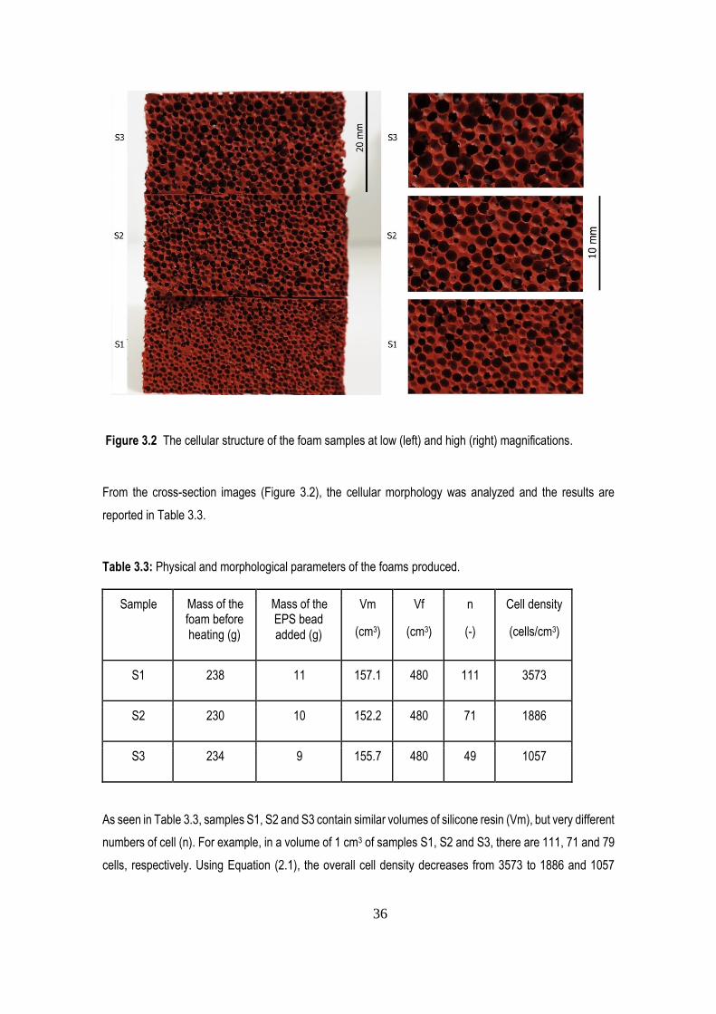
3.4 Compression Properties
As the first step, the unfoamed silicone rubber system (ELASTOSIL® M 4370) was tested under
compression. Five specimens were cut with areas of 47 mm by 47 mm and a thickness of 20 mm before
being subjected to compressive loads up to 3650 N (close to the load cell capacity of 5 kN) with a quasi-
static rate of 0.015 s-1 at room temperature. The obtained stress-strain curves are shown in Figure 3.3. This
allowed obtaining the compressive modulus of the silicone rubber which was measured at 3030 kPa.
Figure 3.3 Compressive stress-strain curve obtained for the unfoamed silicone rubber.
The foam samples were then tested for their compression properties as described in Chapter 3. A total of
nine specimens were prepared (three specimens from each sample as shown in Figure 2.6) and
compressed with a quasi-static rate of 0.015 s-1 at room temperature. The compression stress-strain curves
obtained are shown in Figures 3.4 to 3.6 for samples S1 to S3, respectively.
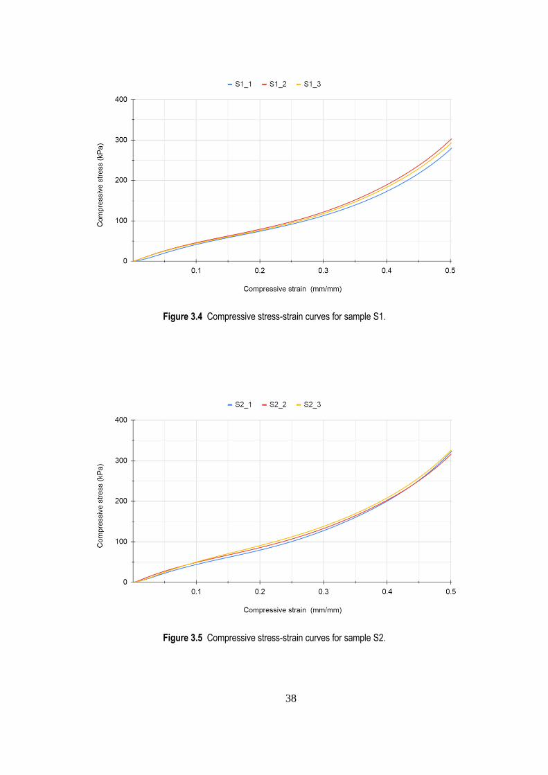
38
Figure 3.4 Compressive stress-strain curves for sample S1.
Figure 3.5 Compressive stress-strain curves for sample S2.
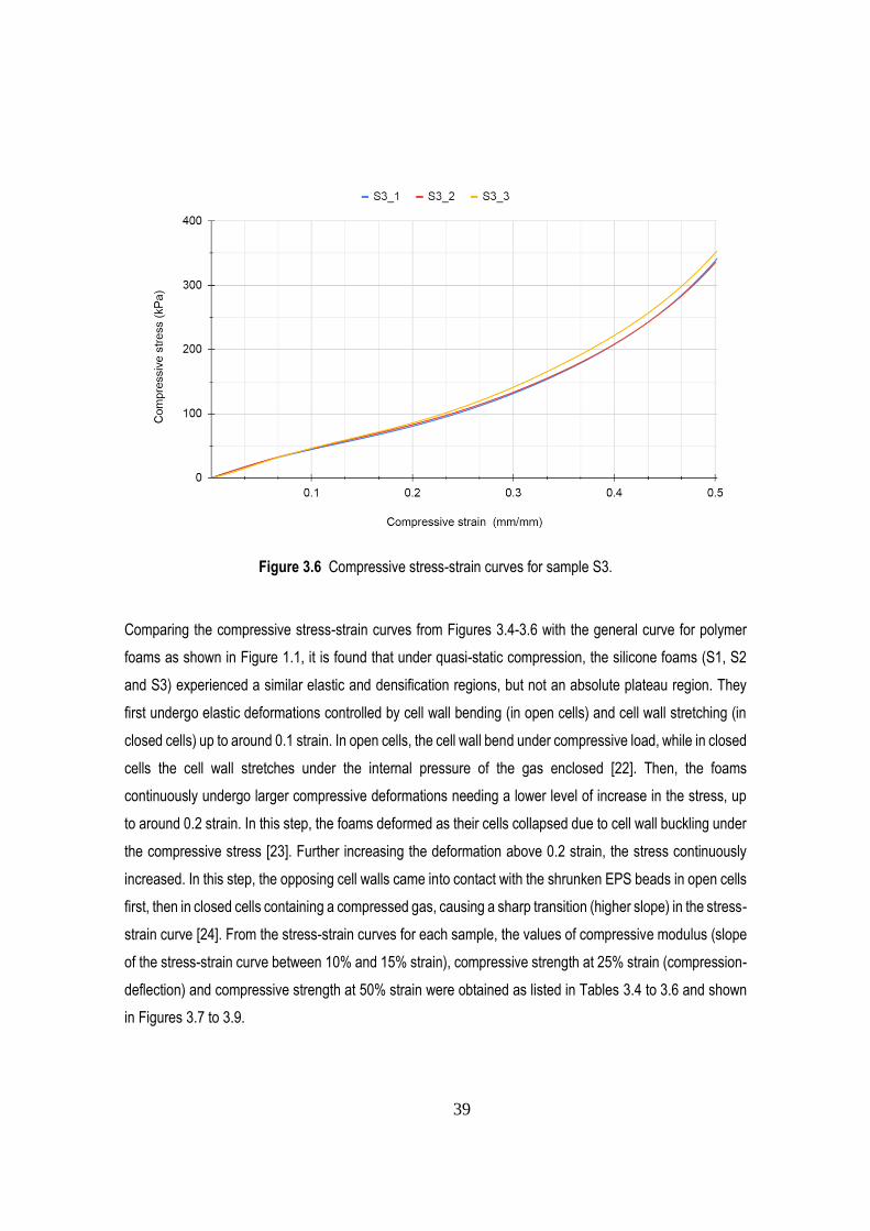
39
Figure 3.6 Compressive stress-strain curves for sample S3.
Comparing the compressive stress-strain curves from Figures 3.4-3.6 with the general curve for polymer
foams as shown in Figure 1.1, it is found that under quasi-static compression, the silicone foams (S1, S2
and S3) experienced a similar elastic and densification regions, but not an absolute plateau region. They
first undergo elastic deformations controlled by cell wall bending (in open cells) and cell wall stretching (in
closed cells) up to around 0.1 strain. In open cells, the cell wall bend under compressive load, while in closed
cells the cell wall stretches under the internal pressure of the gas enclosed [22]. Then, the foams
continuously undergo larger compressive deformations needing a lower level of increase in the stress, up
to around 0.2 strain. In this step, the foams deformed as their cells collapsed due to cell wall buckling under
the compressive stress [23]. Further increasing the deformation above 0.2 strain, the stress continuously
increased. In this step, the opposing cell walls came into contact with the shrunken EPS beads in open cells
first, then in closed cells containing a compressed gas, causing a sharp transition (higher slope) in the stress-
strain curve [24]. From the stress-strain curves for each sample, the values of compressive modulus (slope
of the stress-strain curve between 10% and 15% strain), compressive strength at 25% strain (compression-
deflection) and compressive strength at 50% strain were obtained as listed in Tables 3.4 to 3.6 and shown
in Figures 3.7 to 3.9.
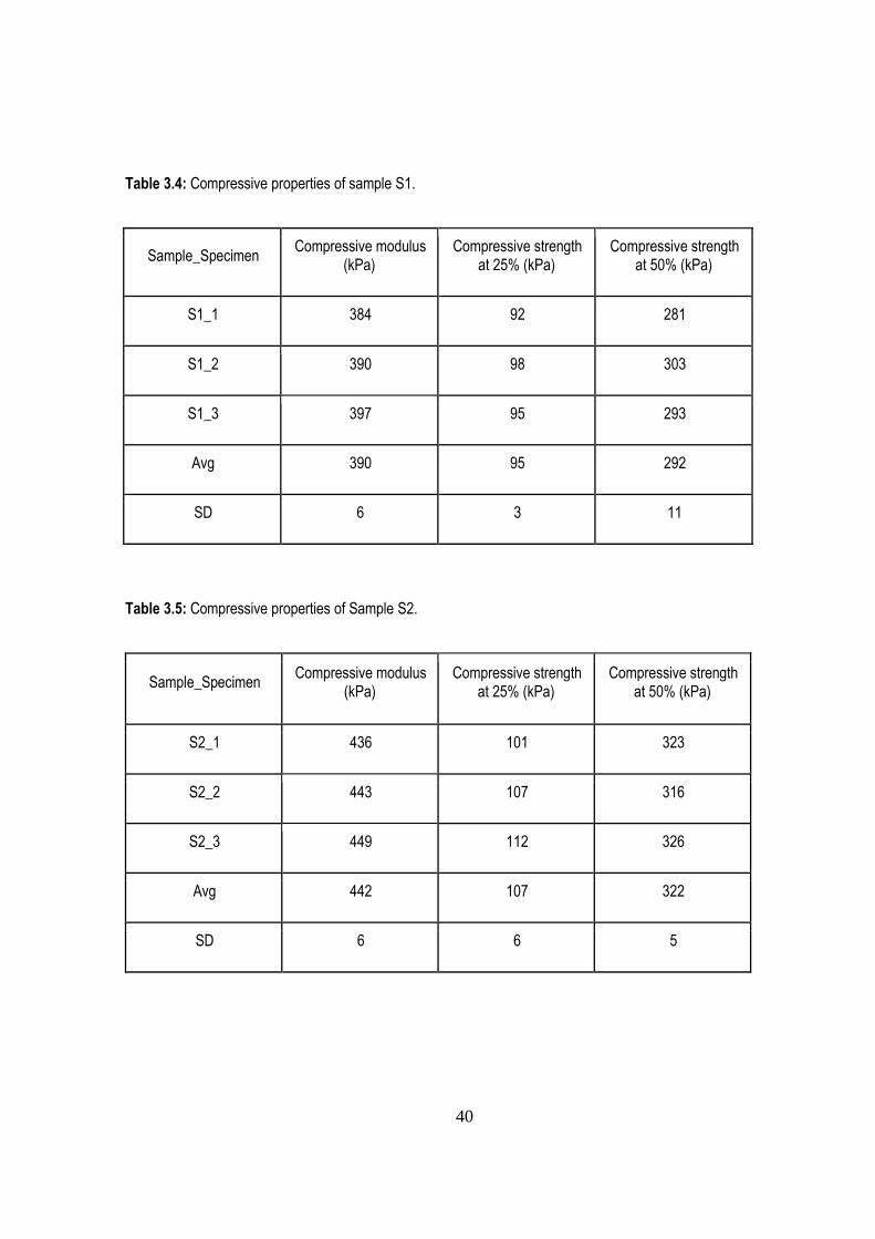
40
Table 3.4: Compressive properties of sample S1.
Sample_Specimen Compressive modulus
(kPa) Compressive strength
at 25% (kPa) Compressive strength
at 50% (kPa)
S1_1 384 92 281
S1_2 390 98 303
S1_3 397 95 293
Avg 390 95 292
SD 6 3 11
Table 3.5: Compressive properties of Sample S2.
Sample_Specimen Compressive modulus
(kPa) Compressive strength
at 25% (kPa) Compressive strength
at 50% (kPa)
S2_1 436 101 323
S2_2 443 107 316
S2_3 449 112 326
Avg 442 107 322
SD 6 6 5
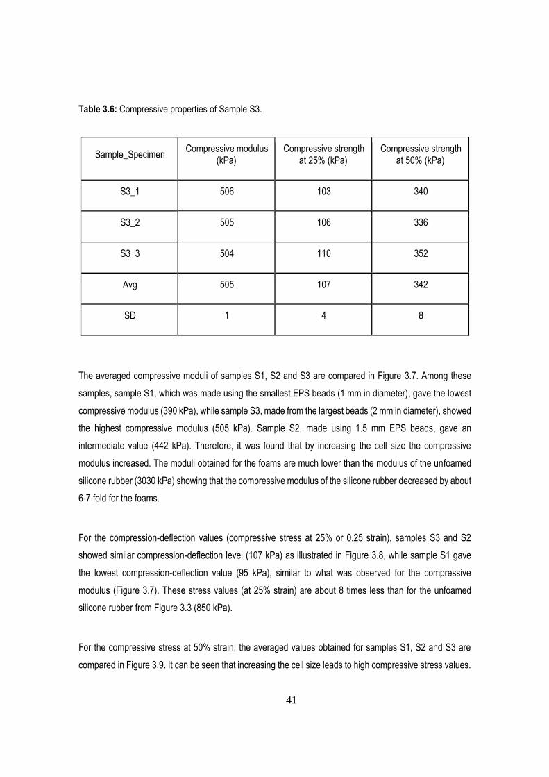
41
Table 3.6: Compressive properties of Sample S3.
Sample_Specimen Compressive modulus
(kPa) Compressive strength
at 25% (kPa) Compressive strength
at 50% (kPa)
S3_1 506 103 340
S3_2 505 106 336
S3_3 504 110 352
Avg 505 107 342
SD 1 4 8
The averaged compressive moduli of samples S1, S2 and S3 are compared in Figure 3.7. Among these
samples, sample S1, which was made using the smallest EPS beads (1 mm in diameter), gave the lowest
compressive modulus (390 kPa), while sample S3, made from the largest beads (2 mm in diameter), showed
the highest compressive modulus (505 kPa). Sample S2, made using 1.5 mm EPS beads, gave an
intermediate value (442 kPa). Therefore, it was found that by increasing the cell size the compressive
modulus increased. The moduli obtained for the foams are much lower than the modulus of the unfoamed
silicone rubber (3030 kPa) showing that the compressive modulus of the silicone rubber decreased by about
6-7 fold for the foams.
For the compression-deflection values (compressive stress at 25% or 0.25 strain), samples S3 and S2
showed similar compression-deflection level (107 kPa) as illustrated in Figure 3.8, while sample S1 gave
the lowest compression-deflection value (95 kPa), similar to what was observed for the compressive
modulus (Figure 3.7). These stress values (at 25% strain) are about 8 times less than for the unfoamed
silicone rubber from Figure 3.3 (850 kPa).
For the compressive stress at 50% strain, the averaged values obtained for samples S1, S2 and S3 are
compared in Figure 3.9. It can be seen that increasing the cell size leads to high compressive stress values.
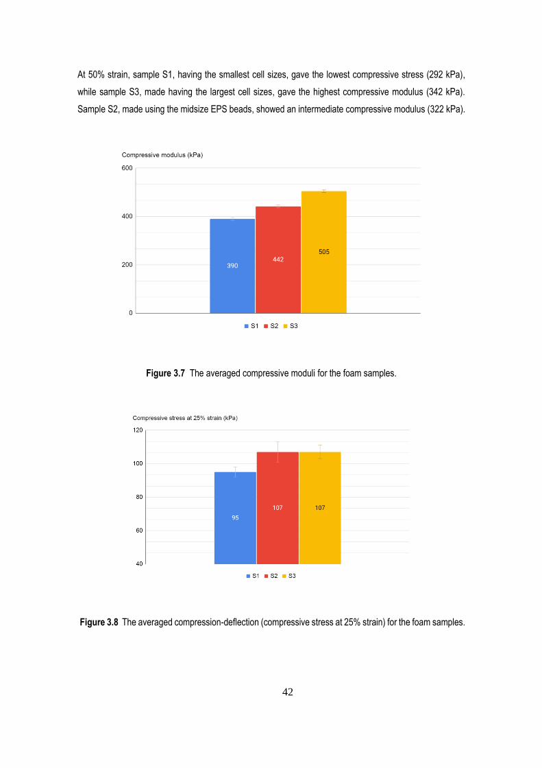
42
At 50% strain, sample S1, having the smallest cell sizes, gave the lowest compressive stress (292 kPa),
while sample S3, made having the largest cell sizes, gave the highest compressive modulus (342 kPa).
Sample S2, made using the midsize EPS beads, showed an intermediate compressive modulus (322 kPa).
Figure 3.7 The averaged compressive moduli for the foam samples.
Figure 3.8 The averaged compression-deflection (compressive stress at 25% strain) for the foam samples.
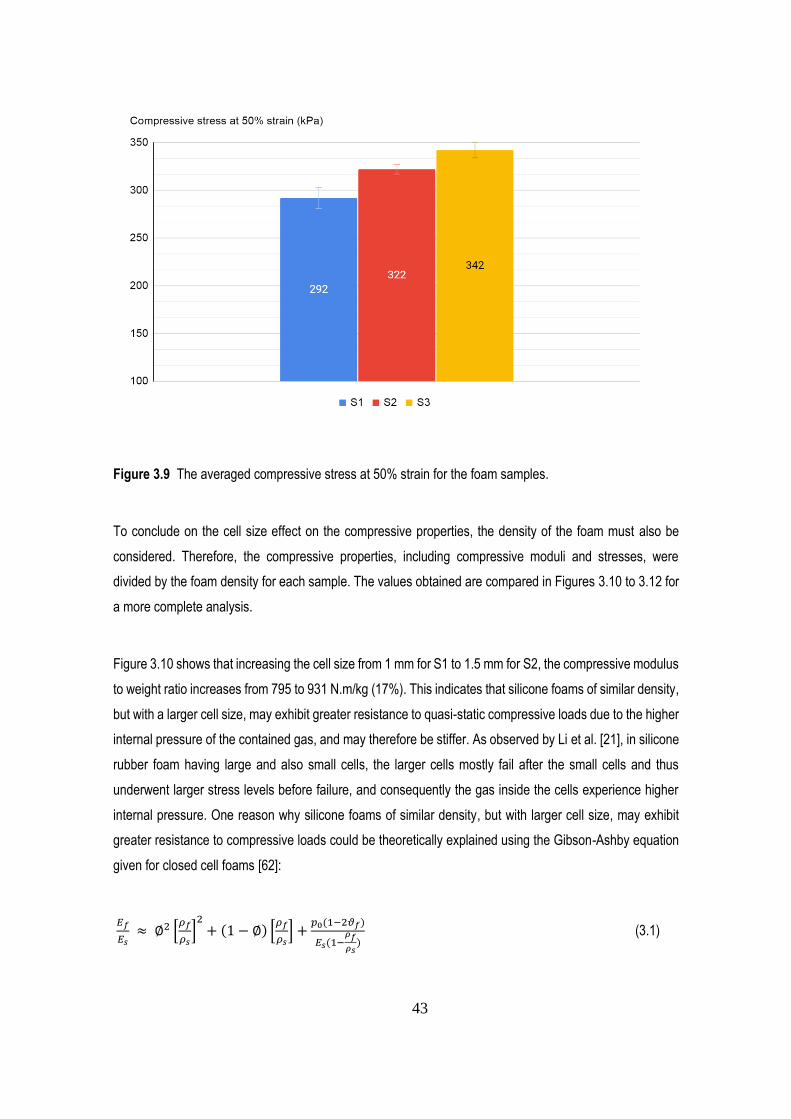
43
Figure 3.9 The averaged compressive stress at 50% strain for the foam samples.
To conclude on the cell size effect on the compressive properties, the density of the foam must also be
considered. Therefore, the compressive properties, including compressive moduli and stresses, were
divided by the foam density for each sample. The values obtained are compared in Figures 3.10 to 3.12 for
a more complete analysis.
Figure 3.10 shows that increasing the cell size from 1 mm for S1 to 1.5 mm for S2, the compressive modulus
to weight ratio increases from 795 to 931 N.m/kg (17%). This indicates that silicone foams of similar density,
but with a larger cell size, may exhibit greater resistance to quasi-static compressive loads due to the higher
internal pressure of the contained gas, and may therefore be stiffer. As observed by Li et al. [21], in silicone
rubber foam having large and also small cells, the larger cells mostly fail after the small cells and thus
underwent larger stress levels before failure, and consequently the gas inside the cells experience higher
internal pressure. One reason why silicone foams of similar density, but with larger cell size, may exhibit
greater resistance to compressive loads could be theoretically explained using the Gibson-Ashby equation
given for closed cell foams [62]:
𝐸𝑓
𝐸𝑠 ≈ ∅2 [
𝜌𝑓
𝜌𝑠]
2+ (1 − ∅) [
𝜌𝑓
𝜌𝑠] +
𝑝0(1−2𝜗𝑓)
𝐸𝑠(1−𝜌𝑓
𝜌𝑠)
(3.1)
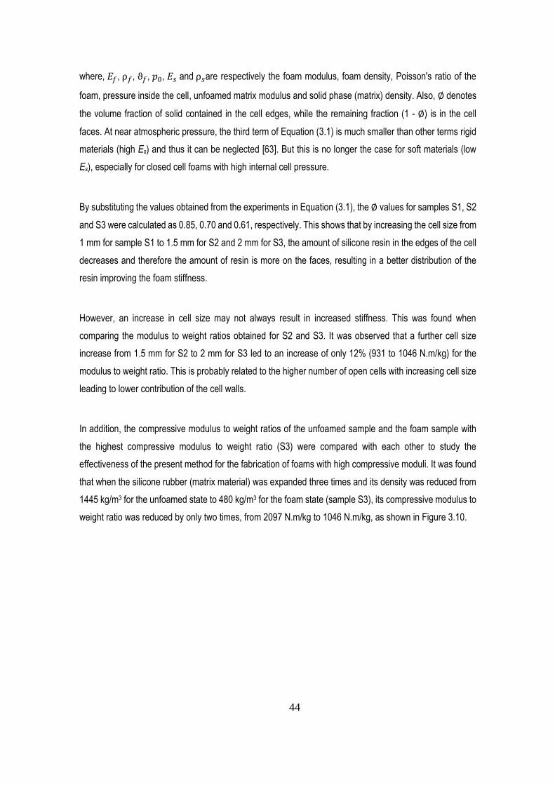
44
where, 𝐸𝑓, ρ𝑓, ϑ𝑓, 𝑝0, 𝐸𝑠 and ρ𝑠are respectively the foam modulus, foam density, Poisson's ratio of the
foam, pressure inside the cell, unfoamed matrix modulus and solid phase (matrix) density. Also, ∅ denotes
the volume fraction of solid contained in the cell edges, while the remaining fraction (1 - ∅) is in the cell
faces. At near atmospheric pressure, the third term of Equation (3.1) is much smaller than other terms rigid
materials (high Es) and thus it can be neglected [63]. But this is no longer the case for soft materials (low
Es), especially for closed cell foams with high internal cell pressure.
By substituting the values obtained from the experiments in Equation (3.1), the ∅ values for samples S1, S2
and S3 were calculated as 0.85, 0.70 and 0.61, respectively. This shows that by increasing the cell size from
1 mm for sample S1 to 1.5 mm for S2 and 2 mm for S3, the amount of silicone resin in the edges of the cell
decreases and therefore the amount of resin is more on the faces, resulting in a better distribution of the
resin improving the foam stiffness.
However, an increase in cell size may not always result in increased stiffness. This was found when
comparing the modulus to weight ratios obtained for S2 and S3. It was observed that a further cell size
increase from 1.5 mm for S2 to 2 mm for S3 led to an increase of only 12% (931 to 1046 N.m/kg) for the
modulus to weight ratio. This is probably related to the higher number of open cells with increasing cell size
leading to lower contribution of the cell walls.
In addition, the compressive modulus to weight ratios of the unfoamed sample and the foam sample with
the highest compressive modulus to weight ratio (S3) were compared with each other to study the
effectiveness of the present method for the fabrication of foams with high compressive moduli. It was found
that when the silicone rubber (matrix material) was expanded three times and its density was reduced from
1445 kg/m3 for the unfoamed state to 480 kg/m3 for the foam state (sample S3), its compressive modulus to
weight ratio was reduced by only two times, from 2097 N.m/kg to 1046 N.m/kg, as shown in Figure 3.10.
45
Figure 3.10 The compressive modulus to weight ratio for the foam samples.
A similar trend to Figure 3.8 is observed for the compression-deflection to weight ratio. As shown in Figure
3.11, increasing the cell size from 1 mm for S1 to 1.5 mm for S2 increased the compression-deflection to
weight ratio from 193 to 224 N.m/kg (14%) indicating that silicone foams of the same density, but with a
larger cell sizes, may exhibit higher compression-deflection due to the higher internal gas pressure of the
cell. However, similar to the modulus to weight ratio trend (Figure 3.10), increasing the cell size may not
always increase the compression-deflection level. As shown in Figure 3.11, further cell size increase from
1.5 mm for S2 to 2 mm for S3 slightly decreased the compression-deflection to weight ratio from 224 to 221
N.m/kg (1%), due to the increased number of open cells. However, the effect of open cells on the
compressive behavior of the foams at the beginning of the compression process is less pronounced than at
larger deformations. This is because the ratio of the closed cells to open cells at the beginning of the test is
greater than that at larger deformations. At a deformation of around 2.5% strain, where the modulus is
calculated, most of the closed cells were not broken and can resist/sustain the internal pressure of the
contained gas, while at 25%, where the compression-deflection is calculated, a high number of closed cells
were broken.
In addition, the compression-deflection to weight ratios of the unfoamed sample and the foam samples were
compared with each other to study the impact of the present foaming method on the compression-deflection
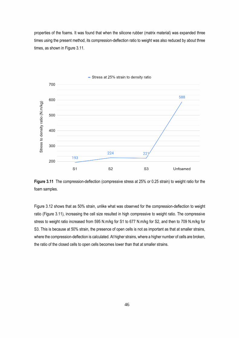
46
properties of the foams. It was found that when the silicone rubber (matrix material) was expanded three
times using the present method, its compression-deflection ratio to weight was also reduced by about three
times, as shown in Figure 3.11.
Figure 3.11 The compression-deflection (compressive stress at 25% or 0.25 strain) to weight ratio for the
foam samples.
Figure 3.12 shows that as 50% strain, unlike what was observed for the compression-deflection to weight
ratio (Figure 3.11), increasing the cell size resulted in high compressive to weight ratio. The compressive
stress to weight ratio increased from 595 N.m/kg for S1 to 677 N.m/kg for S2, and then to 709 N.m/kg for
S3. This is because at 50% strain, the presence of open cells is not as important as that at smaller strains,
where the compression-deflection is calculated. At higher strains, where a higher number of cells are broken,
the ratio of the closed cells to open cells becomes lower than that at smaller strains.
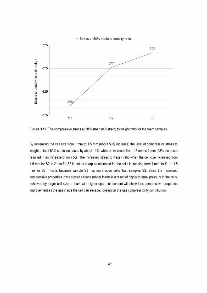
47
Figure 3.12 The compressive stress at 50% strain (0.5 strain) to weight ratio for the foam samples.
By increasing the cell size from 1 mm to 1.5 mm (about 50% increase) the level of compressive stress to
weight ratio at 50% strain increased by about 14%, while an increase from 1.5 mm to 2 mm (28% increase)
resulted in an increase of only 5%. The increased stress to weight ratio when the cell size increased from
1.5 mm for S2 to 2 mm for S3 is not as sharp as observed for the cells increasing from 1 mm for S1 to 1.5
mm for S2. This is because sample S3 has more open cells than samples S2. Since the increased
compressive properties in the closed silicone rubber foams is a result of higher internal pressure in the cells,
achieved by larger cell size, a foam with higher open cell content will show less compressive properties
improvement as the gas inside the cell can escape, loosing on the gas compressibility contribution.
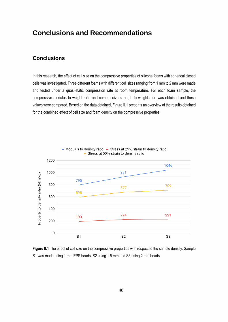
48
Conclusions and Recommendations
Conclusions
In this research, the effect of cell size on the compressive properties of silicone foams with spherical closed
cells was investigated. Three different foams with different cell sizes ranging from 1 mm to 2 mm were made
and tested under a quasi-static compression rate at room temperature. For each foam sample, the
compressive modulus to weight ratio and compressive strength to weight ratio was obtained and these
values were compared. Based on the data obtained, Figure II.1 presents an overview of the results obtained
for the combined effect of cell size and foam density on the compressive properties.
Figure II.1 The effect of cell size on the compressive properties with respect to the sample density. Sample
S1 was made using 1 mm EPS beads, S2 using 1.5 mm and S3 using 2 mm beads.
49
From the results obtained, several conclusions can be made:
i) The method of using shrinkable beads to form the foam cells made it possible to produce homogeneous
foams with similar densities, but with different cell sizes.
ii) The cell size affects the quasi static compressive behavior of the silicone rubber foams in different ways.
iii) In closed cell silicone rubber foams, the compressive modulus increased by increasing the cell size for
the range of conditions investigated.
iv) Among the closed cell rubber foams having the same matrix composition and similar densities, but
different cell sizes, the one having the smallest cell size gave the lowest compressive properties to weight
ratio, while the one with the largest cell size gave the highest ratio when they are slowly compressed (0.015
s-1).
v) Increased compressive properties in the silicone rubber foams is a result of higher contribution of the
internal cell pressure, especially in larger cell sizes.
vi) For the closed cell silicone rubber foams with densities around 480 kg/m3, increasing the cell size from 1
mm to 1.5 mm increased the compressive modulus by 17%, as well as the compression-deflection and
compressive stress at 50% strain by 14%.
vii) For silicone rubber foams with similar densities, increasing the cell size may not always result in improved
compressive properties, depending on the ratio between closed cells and open cells as the internal gas
pressure is less important for the latter.
viii) For silicone rubber foams containing some open cells, the effect of open cells content on the foam
compressive behavior is different between the beginning of the compression test (small strains) compared
to later stages (larger deformations). This is because the ratio of closed cells to open cells changes and cell
walls contributions decrease with increasing deformation.
50
ix) For silicone rubber foams with similar densities, when increasing the cell size, a foam with higher open
cell content is producing leading to lower compressive properties due lower contribution of the cell walls and
the internal gas pressure compressibility.
Recommendations for Future Works
Based on the findings from this research, the following recommendations are made for further development:
i) To study the mechanical behavior of silicone rubber foams under other types of deformation:
tension, impact, bending, multi-axial, etc.
ii) To study the effects of different fillers/reinforcements on the mechanical behavior of composite
silicone rubber foams. This includes different types, sizes and geometry of particles.
iii) To study the effect of cell size and density on the thermal properties (heat conductivity) of silicone
rubber foams.
iv) To study the effect of other cell parameters (geometry, deformation, density) on the overall
properties of silicone rubber foams.
v) To investigate the possibility of using the EPS-based foaming technique to other types of rubbers
like polyurethane, polyisocyanurate, etc.
51
References
[1] Lee, S.T. and Ramesh, N.S. Eds., 2004. Polymeric foams: mechanisms and materials. CRC press.
[2] Frisch, K.C., 1981. History of science and technology of polymeric foams. Journal of Macromolecular
Science-Chemistry, 15(6), pp.1089-1112.
[3] Verdejo, R., Saiz-Arroyo, C., Carretero-Gonzalez, J., Barroso-Bujans, F., Rodriguez-Perez, M.A. and
Lopez-Manchado, M.A., 2008. Physical properties of silicone foams filled with carbon nanotubes and
functionalized graphene sheets. European Polymer Journal, 44(9), pp.2790-2797.
[4] Polymer Foam Market by Types, Applications & Geography - Global Trends & Forecasts to 2018, Access
:8 March 2020, https://www.prnewswire.com/news-releases/polymer-foam-market-by-types-applications--
geography---global-trends--forecasts-to-2018-253825961.html
[5] Khemani KC., 1997. Polymeric foams: science and technology, American Chemical Society.
[6] Ojeda T., 2013. Polymers and the Environment, In Polymer Science, Yılmaz, F., Ed.; InTech.
[7] Tang W., Liao X., Zhang Y., Li J., Wang G. and Li G., 2019. Mechanical–microstructure relationship and
cellular failure mechanism of silicone rubber foam by the cell microstructure designed in supercritical CO2.
The Journal of Physical Chemistry C, 123(44), pp.26947-26956.
[8] Xiang, B., Deng, Z., Zhang, F., Wen, N., Lei, Y., Liu, T. and Luo, S., 2019. Microcellular silicone rubber
foams: The influence of reinforcing agent on cellular morphology and nucleation. Polymer Engineering &
Science, 59(1), pp.5-14.
[9] Understanding Foam Densities, Access: 31 March 2021, https://www.thesleepjudge.com/understanding-
foam-densities/
[10] Willett JL, Shogren RL., 2002. Processing and properties of extruded starch/polymer foams. Polymer,
43(22), pp.5935-5947.
[
T
y
p
e
a
q
u
o
t
e
f
r
o
m
t
h
e
d
o
c
u
m
e
n
t
o
r
t
h
e
s
u
m
m
a
r
y
52
[11] Sharifishourabi G., Rodrigue D., 2020. Elastomeric composites and methods for producing same,
Patent application (CA2019051747).
[12] Shit, S.C. and Shah, P., 2013. A review on silicone rubber. National Academy Science Letters, 36(4),
pp.355-365.
[13] Métivier, T. and Cassagnau, P., 2019. New trends in cellular silicone: Innovations and applications.
Journal of Cellular Plastics, 55(2), pp.151-200.
[14] What’s the Difference Between Foam Rubber vs. Sponge Rubber? Access: 8 March 2020,
https://www.elastoproxy.com/foam-rubber-vs-sponge-rubber-whats-difference/
[15] Silicone Foam for Gaskets, Cushioning Pads, Tape, Access: 8 March 2020,
https://www.stockwell.com/silicone-foam/
[16] Silicone Sponge Rubber Products, Gaskets, Cushions, Access: 8 March 2020,
https://www.stockwell.com/silicone-sponge/
[17] Three Types of Custom Silicone Gaskets, Access: 8 March 2020, https://www.elastoproxy.com/custom-
silicone-gaskets/
[18] Rail, Access: 8 March 2020, https://cbfrost-rubber.com/sectors/rail/
[19] Zhao, X. and Zhang, J., 2019. A novel composite silicone foam with enhanced safeguarding
performance and self-healing property. Reactive and Functional Polymers, 138, pp.114-121.
[20] Wu, X., Dong, L., Zhang, F., Zhou, Y., Wang, L., Wang, D. and Yin, Y., 2016. Preparation and
characterization of three phase epoxy syntactic foam filled with carbon fiber reinforced hollow epoxy
macrospheres and hollow glass microspheres. Polymer Composites, 37(2), pp.497-502.
53
[21] Li, J. and Guo, K., 2007. In-situ observation of tensile and compression processes of MVQ foam. China
Rubber Industry, 54(2), p.84.
[22] Eaves D., 2004. Handbook of polymer foams Rapra Technology Limited, United Kingdom, 25(6):1-2.
[23] Gupta, N., Woldesenbet, E. and Sankaran, S., 2001. Studies on compressive failure features in
syntactic foam material. Journal of Materials Science, 36(18), pp.4485-4491.
[24] Bai, J., Liao, X., Huang, E., Luo, Y., Yang, Q. and Li, G., 2017. Control of the cell structure of
microcellular silicone rubber/nanographite foam for enhanced mechanical performance. Materials & Design,
133, pp.288-298.
[25] Lee, C.L., Niemi, R.G. and Kelly, K.M., 1977. New silicone RTV foam. Journal of Cellular Plastics, 13(1),
pp.62-67.
[26] Jenkins, M. Ed., 2007. Biomedical polymers. Elsevier.
[27] Chandrasekhar, V., 2005. Polysiloxanes. Inorganic and Organometallic Polymers, pp.209-248.
[28] Seethapathy, S. and Gorecki, T., 2012. Applications of polydimethylsiloxane in analytical chemistry: A
review. Analytica Chimica Acta, 750, pp.48-62.
[29] Mrozek, R.A., Cole, P.J., Otim, K.J., Shull, K.R. and Lenhart, J.L., 2011. Influence of solvent size on the
mechanical properties and rheology of polydimethylsiloxane-based polymeric gels. Polymer, 52(15),
pp.3422-3430.
[30] Benahmed, A., Lam, R., Rechner, N. and Ho, C.M., 2007. Period and height control during the
microcontact printing of alkoxysilane for optical gratings. Journal of Micro/Nanolithography, MEMS, and
MOEMS, 6(2), p.023007.
[31] Jerschow, P., 2001. Silicone elastomers (Rapra Review Reports). Smithers Rapra Technology.
54
[32] Jawhar, M.C.D., Blanc, D., Chaumont, P. and Cassagnau, P., 2014. Study of the coalescence
mechanisms during silicone foaming. Macromolecular Materials and Engineering, 299(3), pp.336-343.
[33] Lorenz, G. and Kandelbauer, A., 2014. Silicones. In Handbook of Thermoset Plastics, William Andrew
Publishing, pp. 555-575.
[34] Hopmann, C., Kammer, S., Fey, F. and Facklam, M., 2020. Foam Extrusion of Elastomers using Water
as Physical Blowing Agent. In Advances in Polymer Processing 2020 (pp. 63-78). Springer Vieweg, Berlin,
Heidelberg.
[35] Chruściel, J.J. and Leśniak, E., 2011. Preparation of flexible, self‐extinguishing silicone foams. Journal
of Applied Polymer Science, 119(3), pp.1696-1703.
[36] Weyer, D.E., Dow Corning Corp, 1958. Method of preparing siloxane resin foams. U.S. Patent
2,833,732.
[37] Yazici, M.U.R.A.T., Fahr, P., Shukla, A., Gunes, S. and Akay, S.K., 2014. Development of a polymer
based syntactic foam for high temperature applications. Acta Physica Polonica A, 125(2), pp.526-528.
[38] Blanc, D. and Canpont, D., 2015. Bluestar Silicones France SAS, Silicone composition for elastomer
foam. U.S. Patent 9,056,953.
[39] Kittle, R.E. and Ronk, G.M., 1977. Dow Corning Corp. Method of foaming a siloxane composition using
microwave energy. U.S. Patent 4,026,844.
[40] Nakanishi, M., 1986. Composite Silicone Rubber Material. Patent Number EP 0186493.
[41] Yousaf, Z., Smith, M., Potluri, P. and Parnell, W., 2020. Compression properties of polymeric syntactic
foam composites under cyclic loading. Composites Part B: Engineering, 186, p.107764.
55
[42] Kenig, S., Raiter, I. and Narkis, M., 1984. Three-phase silicone based syntactic foams. Journal of
Cellular Plastics, 20(6), pp.423-429.
[43] Kessler, M., Roggendorf, C. and Schnettler, A., 2012, June. Investigation of the physical properties of
elastic syntactic foams. In 2012 IEEE International Symposium on Electrical Insulation, pp. 526-530.
[44] Schumann, S., Lehretz, F. and Görlich, J., 2016, September. Investigation of mechanical properties of
silicone syntactic foam for outdoor applications. In 2016 IEEE International Conference on High Voltage
Engineering and Application (ICHVE), pp. 1-5.
[45] Alex, A.S., Thomas, D., Manu, S.K., Sreenivas, N., Sekkar, V. and Gouri, C., 2018. Addition-cure, room
temperature vulcanizing silicone elastomer based syntactic foams with glass and ceramic microballoons.
Polymer Bulletin, 75(2), pp.747-767.
[46] Fahr, P., Yazici, M. and Shukla, A., 2018. Shock response of filled corrugated sandwich structures
under extreme temperatures. Journal of Sandwich Structures & Materials, 20(1), pp.130-149.
[47] Abad, C. and Wilson, A., 2015. Schlumberger Technology Corp. Downhole polymer foam applications.
U.S. Patent 9,140,107.
[48] Hong, I.K. and Lee, S., 2014. Microcellular foaming of silicone rubber with supercritical carbon dioxide.
Korean Journal of Chemical Engineering, 31(1), pp.166-171.
[49] Jia, Y., Xiang, B., Zhang, W., Liu, T. and Luo, S., 2020. Microstructure and properties of microcellular
silicone rubber foams with improved surface quality. Polymer Journal, 52(2), pp.207-216.
[50] Liao, X., Xu, H., Li, S., Zhou, C., Li, G. and Park, C.B., 2015. The effects of viscoelastic properties on
the cellular morphology of silicone rubber foams generated by supercritical carbon dioxide. RSC Advances,
5(129), pp.106981-106988.
56
[51] Yang, Q., Yu, H., Song, L., Lei, Y., Zhang, F., Lu, A., Liu, T. and Luo, S., 2017. Solid‐state microcellular
high temperature vulcanized (HTV) silicone rubber foam with carbon dioxide. Journal of Applied Polymer
Science, 134(20), p. 44807.
[52] Hagen, P., 1999. Extruded foamed silicone rubber composition and method for making same. U.S.
Patent 5,985,947.
[53] Park, E.S., 2008. Mechanical properties and antibacterial activity of peroxide‐cured silicone rubber
foams. Journal of Applied Polymer Science, 110(3), pp.1723-1729.
[54] Gao, J., Wang, J., Xu, H. and Wu, C., 2013. Preparation and properties of hollow glass bead filled
silicone rubber foams with low thermal conductivity. Materials & Design, 46, pp.491-496.
[55] Bruner, J.L.B., 1962, Dow Corning Corp. Method of preparing organosiloxane elastomer foams. U.S.
Patent 3,070,555.
[56] Jawhar, M.C.D., Blanc, D., Chaumont, P. and Cassagnau, P., 2014. Study of the coalescence
mechanisms during silicone foaming. Macromolecular Materials and Engineering, 299(3), pp.336-343.
[57] Verdejo, R., Barroso-Bujans, F., Rodriguez-Perez, M.A., De Saja, J.A. and Lopez-Manchado, M.A.,
2008. Functionalized graphene sheet filled silicone foam nanocomposites. Journal of Materials Chemistry,
18(19), pp.2221-2226.
[58] Liu, M., Yu, L., Vudayagiri, S. and Skov, A.L., 2020. Incorporation of liquid fillers into silicone foams to
enhance the electro-mechanical properties. International Journal of Smart and Nano Materials, 11(1), pp.11-
23.
[59] Kim, Y.W. and Park, C.B., 2003. Processing of microcellular preceramics using carbon dioxide.
Composites Science and Technology, 63(16), pp.2371-2377.
57
[60] Compression Deflection, Accessed on 13 March 2020,
https://www.alanto.co.uk/information/glossary/what-does-compression-deflection-mean
[61] ELASTOSIL® M 4370 A/B, Accessed on 12 Feb. 2020, https://www.wacker.com/h/en-
us/medias/ELASTOSIL-M-4370-AB-en-2020.07.01.pdf
[62] Ashby, M.F. and Gibson, L.J., 1995, Cellular solids, structure and properties. Cambridge University
Press.
[63] Ma, Y., Su, X., Pyrz, R. and Rauhe, J.C., 2013. A novel theory of effective mechanical properties of
closed-cell foam materials. Acta Mechanica Solida Sinica, 26(6), pp.559-569.


![Magnetic quasi-static simulation [coreless liquid-cooled motor]](https://img.pdfslide.net/doc/110x75/56816864550346895ddeb859/magnetic-quasi-static-simulation-coreless-liquid-cooled-motor.jpg)