Embed Size (px)
Citation preview
International Research Journal of Engineering and Technology (IRJET) e-ISSN: 2395-0056
Volume: 05 Issue: 09 | Sept 2018 www.irjet.net p-ISSN: 2395-0072
© 2018, IRJET | Impact Factor value: 7.211 | ISO 9001:2008 Certified Journal | Page 255
Effect of freely rotating cylinder mounted near the trailing edge of the
wing for boundary layer separation delay
Vinayaka D M1 and Jamehdar Kouser Mubeena2
1,2Aerospace Engineering Graduate, Alliance University, Bengaluru, Karnataka, India ---------------------------------------------------------------------***---------------------------------------------------------------------
Abstract - The Magnus effect is well-known for its flight performance. Therefore, in the present work concept of Magnus effect combined with circulation theory is applied in designing a full-scale wing in-order to overcome main aerodynamic problems. The full-scale model of a freely rotating cylinder with the fixed axis of rotation mounted at three-fifths of chord length from the leading edge of the wing is developed using SOLIDWORKS. And the flow analysis of the same was solved using Fluidyn at transonic speeds. When compared the computational results of a modified wing with the original NACA wing, it is observed to have delayed boundary layer separation, in turn, there is a considerable increase in lift coefficient at lower AOA and further stall angle is elevated to 24 degrees. Hence this modified wing design can be applied for all airplanes to have better fight performance at the lower angles.
Key Words: Angle of attack, Lift coefficient, Drag coefficient, Boundary layer separation, Turbulence models, L/D Ratio etc …
1. INTRODUCTION
Magnus introduced the effect of rotating the cylinder to create lift based on which Flettner used the rotating cylinder capable of creating high lift coefficient and extracting the wind energy but very few air vehicle structures were successful [1]. High lift devices were applied in a sailboat to reduce the pressure drag and rotor wing used to create high lift but produces maximum drag as well. The Magnus effect could be applied only over symmetrical bodies like a spinning ball or a cylinder or a disc [2].
Fig -1: Illustration of Magnus effect on a circular object [19].
Either cargo or commercial, every aircraft needs to have a high lift coefficient at lower angles because drag effect will be less [3]. Researchers have done the work regarding the above by their unique ideas, some of them worked on the surface modifications like dimpled aerofoils to improve the stall characteristics along with the better lift coefficients [4] [5] [6]. Many of them considered the use of vortex
generators to reduce the drag of the aerofoil is a better way [7] and others did work on the movable parts of the wing like flaps to increase the lift coefficients by increasing its camber [8] [9] [10].
Several studies were made on symmetrical aerofoil and hydrofoils with the rotating cylinder at different locations of the wing and at different speed ratios to understand the boundary layer growth and to delay in stall angles, effect of cylinder on the lift and drag coefficient of the aerofoil [11] [12] [13] [14] [15]. Prandtl theorized the description of boundary layer where viscous forces dominate over initial forces [1] [16] [17]. It is observed that flow separation occurs near the intersection of fixed and moving walls when the cylinder is not rotating, but when it is rotating the boundary layer separation delays [14] [18].
2. METHODOLOGY
The process of Original and Modified wing designs was carried out by using the 3D geometric software SOLIDWORKS with the following design specifications mentioned in the tables 1 and 2.
Table -1: Specifications of original aircraft wing [19]
Sl no. Description Dimension
01 Airfoil type NACA 2412
02 Chord length 1.97327044
03 Wing type Rectangular wing
04 Aspect ratio (b2/s) 6.446
05 Wing span 12.72 m
06 Wing area 25.1 m2
07 Wing shape Cambered
Table -2: Specifications of cylinder mounted on modified
wing
Sl no. Description Dimension
01 Cylinder type Hollow cylinder
02 Cylinder Area 0.0551 m2
03 Cylinder Length 12.48 m
International Research Journal of Engineering and Technology (IRJET) e-ISSN: 2395-0056
Volume: 05 Issue: 09 | Sept 2018 www.irjet.net p-ISSN: 2395-0072
© 2018, IRJET | Impact Factor value: 7.211 | ISO 9001:2008 Certified Journal | Page 256
04 Location of cylinder in wing along x-direction
1.189 m
05 Location of cylinder in wing along y-direction
0.09 m
06 Outer Cylinder Diameter 0.095 m
07 Inner Cylinder Diameter 0.040 m
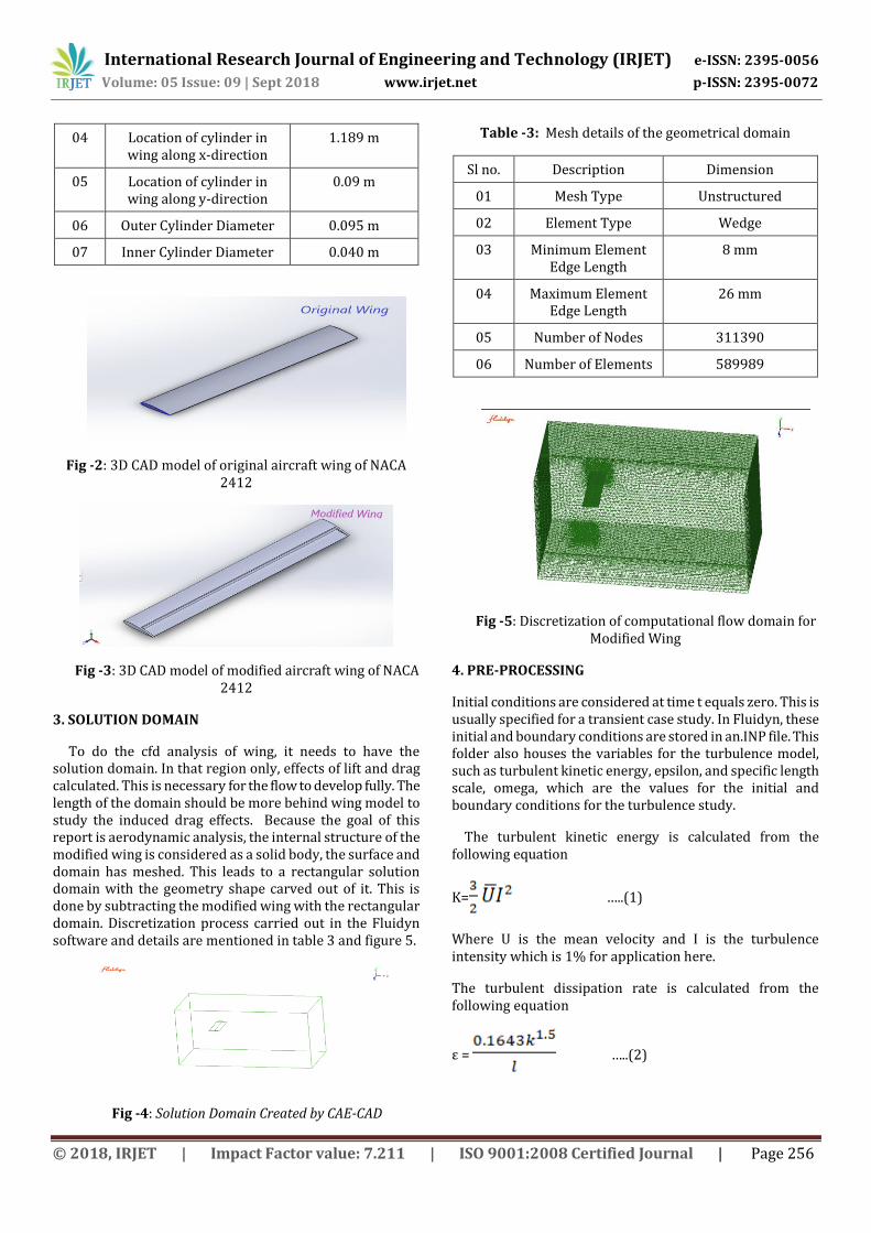
Fig -2: 3D CAD model of original aircraft wing of NACA 2412
Fig -3: 3D CAD model of modified aircraft wing of NACA 2412
3. SOLUTION DOMAIN
To do the cfd analysis of wing, it needs to have the solution domain. In that region only, effects of lift and drag calculated. This is necessary for the flow to develop fully. The length of the domain should be more behind wing model to study the induced drag effects. Because the goal of this report is aerodynamic analysis, the internal structure of the modified wing is considered as a solid body, the surface and domain has meshed. This leads to a rectangular solution domain with the geometry shape carved out of it. This is done by subtracting the modified wing with the rectangular domain. Discretization process carried out in the Fluidyn software and details are mentioned in table 3 and figure 5.
Fig -4: Solution Domain Created by CAE-CAD
Table -3: Mesh details of the geometrical domain
Sl no. Description Dimension
01 Mesh Type Unstructured
02 Element Type Wedge
03 Minimum Element Edge Length
8 mm
04 Maximum Element Edge Length
26 mm
05 Number of Nodes 311390
06 Number of Elements 589989
Fig -5: Discretization of computational flow domain for Modified Wing
4. PRE-PROCESSING
Initial conditions are considered at time t equals zero. This is usually specified for a transient case study. In Fluidyn, these initial and boundary conditions are stored in an.INP file. This folder also houses the variables for the turbulence model, such as turbulent kinetic energy, epsilon, and specific length scale, omega, which are the values for the initial and boundary conditions for the turbulence study.
The turbulent kinetic energy is calculated from the following equation
K= …..(1)
Where U is the mean velocity and I is the turbulence intensity which is 1% for application here.
The turbulent dissipation rate is calculated from the following equation
ε = …..(2)
International Research Journal of Engineering and Technology (IRJET) e-ISSN: 2395-0056
Volume: 05 Issue: 09 | Sept 2018 www.irjet.net p-ISSN: 2395-0072
© 2018, IRJET | Impact Factor value: 7.211 | ISO 9001:2008 Certified Journal | Page 257
where is the turbulence length scale which is expressed as
0.07L. the L is the characteristic length.
The types of boundary conditions applied in this case are a velocity inlet and a pressure outlet. A symmetry boundary condition is also applied at the root of the wing. The top, bottom and the side of the solution domain are specified as Wall. A standard no-slip condition is applied to the wing surface.
Table -4: Initial Boundary Conditions used for solving
Sl no. Description Dimension
01 Model k-ε Turbulence Model
02 Fluid Compressible air
03 Flow Condition Turbulence Flow
04 Velocity 274.4 m/s
05 Outlet Pressure Outflow (101325 N/m2)
06 Symmetry Condition Symmetry
07 Far-Field Wall
08 Top and Bottom Wall Wall
09 Convergence Factor 0.0000001
10 Solver Pressure Based
Table -5: Boundary Conditions
Sl no. Description Dimension
01 Pressure 101325N/m2
02 Temperature 300 K
03 Density 1.16 Kg/m3
04 Kinematic Viscosity 1.895e-05
All computational analysis is done using SIMPLEC (Semi-Implicit Method for Pressure-Linked Equations) method. It also allows the user to specify specific solver for each of the scalar parameters such as the number of iterations, convergence factor required by the case setup. Computers are used to solve the governing equations, in this case Navier-stokes equation is used to simulate the interaction of liquids and gases with surfaces defined by initial and boundary conditions.
Turbulence modeling is very important in simple fluid flow, since viscous strength and viscous drag is a significant component of total drag. The turbulence model chosen for this analysis is the k – ε model. It has been proved to give accurate results in flows with relatively small pressure gradients. It is a two-equation model that gives a solution to
each transport equation. These solutions allow one to independently determine the turbulent velocity and the length scales.
This model solves two transport equations for k and ε, which are turbulence kinetic energy (TKE) and the turbulence dissipation rate (TDR) respectively. The equations they are obtained from are shown below,
…(3)
…...(4)
Where, Eij is the component of rate of deformation, μt
represents eddy viscosity and ui represents velocity component in corresponding function.
5. RESULT AND DISCUSSION
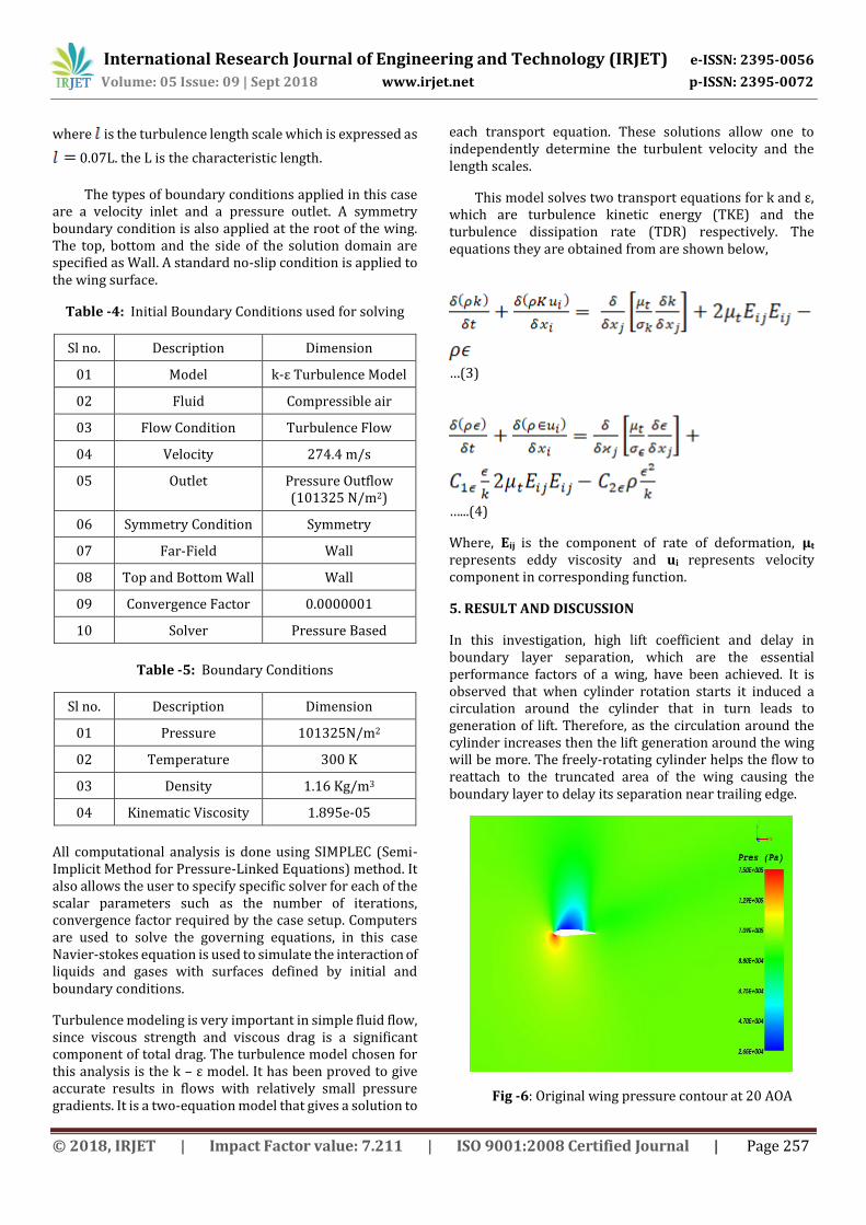
In this investigation, high lift coefficient and delay in boundary layer separation, which are the essential performance factors of a wing, have been achieved. It is observed that when cylinder rotation starts it induced a circulation around the cylinder that in turn leads to generation of lift. Therefore, as the circulation around the cylinder increases then the lift generation around the wing will be more. The freely-rotating cylinder helps the flow to reattach to the truncated area of the wing causing the boundary layer to delay its separation near trailing edge.
Fig -6: Original wing pressure contour at 20 AOA
International Research Journal of Engineering and Technology (IRJET) e-ISSN: 2395-0056
Volume: 05 Issue: 09 | Sept 2018 www.irjet.net p-ISSN: 2395-0072
© 2018, IRJET | Impact Factor value: 7.211 | ISO 9001:2008 Certified Journal | Page 258
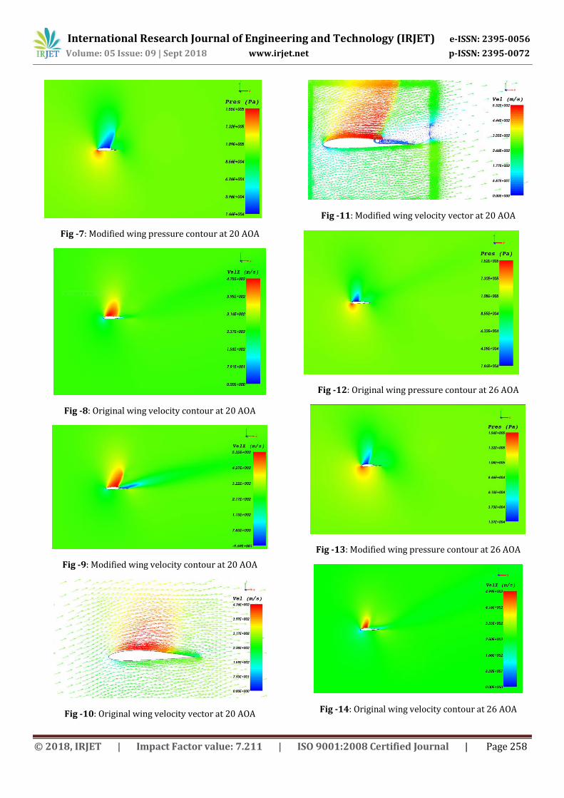
Fig -7: Modified wing pressure contour at 20 AOA
Fig -8: Original wing velocity contour at 20 AOA
Fig -9: Modified wing velocity contour at 20 AOA
Fig -10: Original wing velocity vector at 20 AOA
Fig -11: Modified wing velocity vector at 20 AOA
Fig -12: Original wing pressure contour at 26 AOA
Fig -13: Modified wing pressure contour at 26 AOA
Fig -14: Original wing velocity contour at 26 AOA
International Research Journal of Engineering and Technology (IRJET) e-ISSN: 2395-0056
Volume: 05 Issue: 09 | Sept 2018 www.irjet.net p-ISSN: 2395-0072
© 2018, IRJET | Impact Factor value: 7.211 | ISO 9001:2008 Certified Journal | Page 259
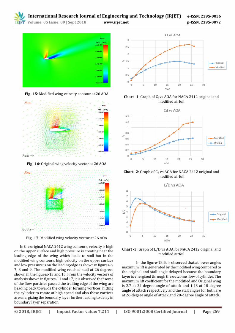
Fig -15: Modified wing velocity contour at 26 AOA
Fig -16: Original wing velocity vector at 26 AOA
Fig -17: Modified wing velocity vector at 26 AOA
In the original NACA 2412 wing contours, velocity is high on the upper surface and high pressure is creating near the leading edge of the wing which leads to stall but in the modified wing contours, high velocity on the upper surface and low pressure is on the leading edge as shown in figures-6, 7, 8 and 9. The modified wing reached stall at 26 degrees shown in the figures-13 and 15. From the velocity vectors of analysis shown in figures-11 and 17, it is observed that some of the flow particles passed the trailing edge of the wing are heading back towards the cylinder forming vortices, hitting the cylinder to rotate at high speed and also these vortices are energizing the boundary layer further leading to delay in boundary layer separation.
Chart -1: Graph of Cl vs AOA for NACA 2412 original and modified airfoil
Chart -2: Graph of Cd vs AOA for NACA 2412 original and modified airfoil
Chart -3: Graph of L/D vs AOA for NACA 2412 original and modified airfoil
In the figure-18, it is observed that at lower angles maximum lift is generated by the modified wing compared to the original and stall angle delayed because the boundary layer is energized through the outcome flow of cylinder. The maximum lift coefficient for the modified and Original wing is 2.7 at 24-degree angle of attack and 1.48 at 18-degree angle of attack respectively and the stall angles for both are at 26-degree angle of attack and 20-degree angle of attack.
International Research Journal of Engineering and Technology (IRJET) e-ISSN: 2395-0056
Volume: 05 Issue: 09 | Sept 2018 www.irjet.net p-ISSN: 2395-0072
© 2018, IRJET | Impact Factor value: 7.211 | ISO 9001:2008 Certified Journal | Page 260
In the figure-19, drag coefficient is relatively high in the modified wing due to the presence of a rotating cylinder when compared to the original. From the analysis, it is observed that cylinder rotation is directly proportional to the drag coefficient.
In the figure-20, for starting 0 to 6 angles of attack in the graph the performance of the modified wing is poor compared to the original wing but for above 6 degrees the aerodynamic efficiency of a wing is much better.
6. CONCLUSIONS
From the project work, it is proved that modified wing is efficient at the higher angle of attack also in stall angle, it is capable of achieving higher lift coefficient at smaller angles and in addition to this, lift to drag ratio is comparatively more at high angles. Stall angle of attack is pushed to 260 whereas in the original wing stall angle is at 200. Comparing with the original wing the modified wing delays the stall angle by 30%. Again at 180 and 240 angles of attack, it showed that the lift coefficient of the modified wing is about 68% and 98% respectively, more than the original wing. Hence increase in the lift coefficient and stall angle of attack would translate into improved maneuverability and performance of the airplane especially during Short Takeoff and Landing (STOL).
If the cylinder moves in the clockwise direction, it will act as a blower and it will energize the boundary layer of the wing after little distance, it helps to achieve the more Cl. Suppose, if it moves in the anti-clockwise direction it will act as sucking pump and it will energize the boundary layer immediately and separates at the trailing edge of the airfoil and separates at the trailing edge of the airfoil and this effect will cause more Cl and Cd of the wing.
REFERENCES
1. Jost Seifert, “A Review of the Magnus effect in aeronautics”, Elsevier publications, 2012.
2. Kavithasan Patkunam1, Samay Sigamani2, Pedaballi Mahathi3, Selvakumaran.T4, “Experimental Study of Magnus Effect over an Arcraft Wing”, International Journal of Research in Engineering and Technology, Oct-2015, Volume: 04 Issue: 10.
3. Dr. John E Matsson et al., “Aerodynamic Performance of the NACA 2412 Airfoil at Low Reynolds Number”, ASEE’s 123rd annual conference and exposition, 2016.
4. Rubiat Mustak et al., “Improvement of aerodynamic characteristics of an airfoil by surface modification”, American Journal of Engineering Research (AJER), 2017.
5. Rubiat Mustak et al., “A Review on surface modification of airfoil using dimples”, international journal of research, 2017.
6. Md. Amzad Hossain et al., “Experimental Study of Aerodynamic Characteristics Of Airfoils Using Different Shaped Dimples”, The International Journal Of Engineering And Science (IJES), 2015.
7. P Jennifer Vinodhini et al., “Numerical analysis of drag reduction method using vortex generator on symmetrical airfoil”, International Journal of Engineering Trends and Technology (IJETT), 2016.
8. Udaya Kumar D et al., “Aerodynamic Analysis of Multi Element Airfoil”, Journal of aeronautics and aerospace engineering, 2016.
9. M. Senthil Kumar et al., “Design and Computational Studies on Plain Flaps”, Bonfring International Journal of Industrial Engineering and Management Science, 2013.
10. Hisham Shehata et al., “Aerodynamic analysis of flapped airfoil at high angles of attack”, AIAA, 2018.
11. Ahmed Z. Al-Garni et al., “Flow control for an airfoil with leading-edge rotation: An experimental study”, American Institute of Aeronautics and Astronautics, 2000.
12. John D Brooks. “Effect of rotating cylinder at the leading edge and trailing edge of the hydrofoil”, Navweps report 8042, 1963.
13. J S. Tennant. “Rotating cylinder for circulation control on an airfoil”, 1976.
14. W S. Johnson et al., “Leading edge rotating cylinder for boundary layer control on lifting surfaces”, AIAA, 1974.
15. V.J. Modi et al., “Moving surface boundary layer control as Applied to two-dimensional airfoils”, American Institute of Aeronautics and Astronautics, 1990.
16. Prandtl L et al., Applied Hydro- and Aero-Mechanics, McGraw-Hill, New York, 1934.
17. John D. Anderson Jr., Fundamentals of Aerodynamics, 5th Edition, McGraw-Hill 2010.
18. J S. Tennant et al., “Turbulent boundary-layer flow from stationary to moving surfaces”, American Institute of Aeronautics and Astronautics, 1973.
International Research Journal of Engineering and Technology (IRJET) e-ISSN: 2395-0056
Volume: 05 Issue: 09 | Sept 2018 www.irjet.net p-ISSN: 2395-0072
© 2018, IRJET | Impact Factor value: 7.211 | ISO 9001:2008 Certified Journal | Page 261
19. Shamil PC et al., “Performance analysis of winglet using CFD”, International Research Journal of Engineering and Technology (IRJET), 2018.
AUTHORS
Myself Vinayaka D M, an Aerospace Engineering Graduate from Alliance University, Bengaluru. Graduated in the month of June, 2018. I have interest in Computational Fluid Dynamics, Aerodynamics and Aircraft structures. I believe that research and development is the key for the betterment of science and technology.
Myself Jamehdar Kouser Mubeena, an Aerospace Engineering Graduate from Alliance University, Bengaluru. I got graduated in the month of June, 2018. I have interest in Aerodynamics, Propulsion and Aircraft structures. I think and consider that technological innovation is important to economic growth.


![VARIO Magnus [e]Magnus](https://img.pdfslide.net/doc/110x75/62e7b22695cddb648811f746/vario-magnus-emagnus.jpg)