Embed Size (px)
Citation preview
ORIGINAL RESEARCH
Effect of Incident Energy and Foil Thickness on Foil Strippingand Scattering Efficiency in Charge Exchange Analyzer Detector
M. Kazemi • M. Habibi • M. Tafreshi
Published online: 21 July 2011
� Springer Science+Business Media, LLC 2011
Abstract Compact neutral particle analyzer (CNPA) is
used to measure ion temperature in tokamaks. Calculating
of stripping efficiency and scattering efficiency are most
important parameters affecting on CNPA performance. We
studied the dependent of these parameters with the thick-
ness of carbon foil and incident energy of neutral hydrogen
atoms. In low carbon foil thickness variation of the carbon
foil stripping efficiency (gi) and scattering efficiency of the
ions (gsc) with incident energy is very salient. For foil
thickness between 200 and 600 angestrom, scattering effi-
ciency of the chamber will be smaller than 0.11.
Keywords Incident energy � Carbon foil thickness �Stripping efficiency � Scattering efficiency
Introduction
Measuring of ion temperature in tokamaks and other
plasma confinement devices requires to use advanced
diagnostic techniques. One of these methodes is neutral
particle analyzing by Compact Charge Exchange Analyzer
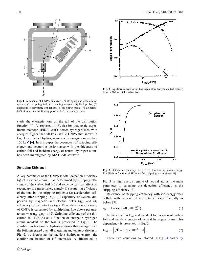
(CNPA) diagnostic. As it shown in Fig. 1, as the incoming
flux of neutral atoms passes through the stripping cell,
many of them become ionized. The ions are deflected by a
magnetic field and measured by channeltron. Each channel
shows the specific energy of primary neutral atoms. The
first use of this techniques (secondary charge exchange
atomic flux) for measuring ion temperature has been
reported by Berezovskii in T-10 tokamak et al. [1]. By
developing the neutral particle analyzing devices, other
parameters like D–T density ratio in the plasma core, were
measured [2]. Neutral beam Plasma heating in fusion
machines need NPAs for controlling and optimization.
Recent studies demonstrate this fact. Specified NPA,
Compact Neutral Particle Analyser (CNPA), developed by
the A. F. Ioffe Physical-Technical Institute, has been
installed on TJ-II [3]. CNPA has many advantages consist
of: (1) It can be installed and easily moved anywhere near a
confined plasma device. (2) Sensitivity of this device for
neutrons and c rays can be very low by good shielding. (3)
Enlarging of analyzer scale increases the influence of outer
magnegtic field on secondary ion trajectories from strip-
ping foil or gas chamber [4]. Specific CNPA shown in
Fig. 1 consist of 6 parts [5]: stripping and acceleration
system, stipping foil, analyzing magnet for producing
magnetic field in perpendecular direction of Ion speed to
deflect them, Hall probe to measure the magnetic field
among the magnet plates, analyzing electrode condenser
for mass resolution (this part causes D? particles impact
on second row of channeltron), shielding mask at the
entrance of the system to reduce sensitivity of light and crays of hot plasma which causes undesirable noise on
external signal, detector to measure the ion energy.
Two kinds of CNPA are used to obtain ion temperatures.
Difference of these two typs is only relevance to stripping
method: stripping with gas chamber (He gas) or utilizing of
Stripping foil (carbon foil). The main advantage of strip-
ping with carbon foil in contrast with gas chamber method
is that the vacuum system of the experimental setup is
sufficient for stripping. In addition, for particles with
energies higher than 10 keV, stripping in a foil is far more
effective than stripping in gas. This may be important to
M. Kazemi (&) � M. Habibi
Amirkabir University of Technology, Tehran, Iran
e-mail: [email protected]
M. Tafreshi
AEOI, Plasma Physics and Fusion Research Center, Tehran, Iran
123
J Fusion Energ (2012) 31:179–183
DOI 10.1007/s10894-011-9447-7
study the energetic ions on the tail of the distribution
function [4]. As reported in [6], fast ion diagnostic exper-
iment methode (FIDE) can’t detect hydrogen ions with
energies higher than 90 keV. While CNPA that shown in
Fig. 1 can detect hydrogen ions with energies more than
150 keV [6]. In this paper the dependent of stripping effi-
ciency and scattering performance with the thickness of
carbon foil and incident energy of neutral hydrogen atoms
has been investigated by MATLAB software.
Stripping Efficiency
A key parameter of the CNPA is total detection efficiency
(g) of incident atoms. It is determined by stripping effi-
ciency of the carbon foil (gi) and some factors that affect on
secondary ion trajectories, namely (1) scattering efficiency
of the ions by the stripping foil (gsc) (2) acceleration effi-
ciency after stripping (gE), (3) capability of system dis-
persion by magnetic and electric fields (gc), and (4)
efficiency of the detectors (gR). Thus, detection efficiency
of CNPA is calculated by multiplying five above parame-
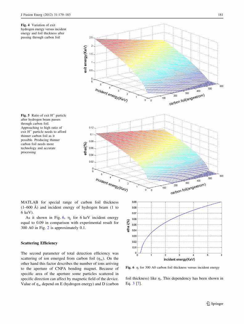
ters:g ¼ gigscgEgcgR [2]. Stripping efficiency of the thin
carbon foil (300 A) as a function of energetic hydrogen
atoms incident on the foil is presented in Fig. 2. The
equilibrium fraction of hydrogen atoms that emerge from
the foil, integrated over all scattering angles. As it shown in
Fig. 2, by increasing the incident hydrogen energy, the
equilibrium fraction of H? increases. As illustrated in
Fig. 3 in high energy regime of neutral atoms, the main
parameter to calculate the detection efficiency is the
stripping efficiency [2].
Relevance of stripping efficiency with ion energy after
collide with carbon foil are obtained experimentally as
below [7]:
gi ¼ 1� exp �0:058 E0:72out
� �: ð1Þ
In this equation Eout is dependent to thickness of carbon
foil and incident energy of neutral hydrogen beam. This
dependency is presented in Eq. 2:
Eout ¼ffiffiffiEp� 1:6� 10�3 � d
h i: ð2Þ
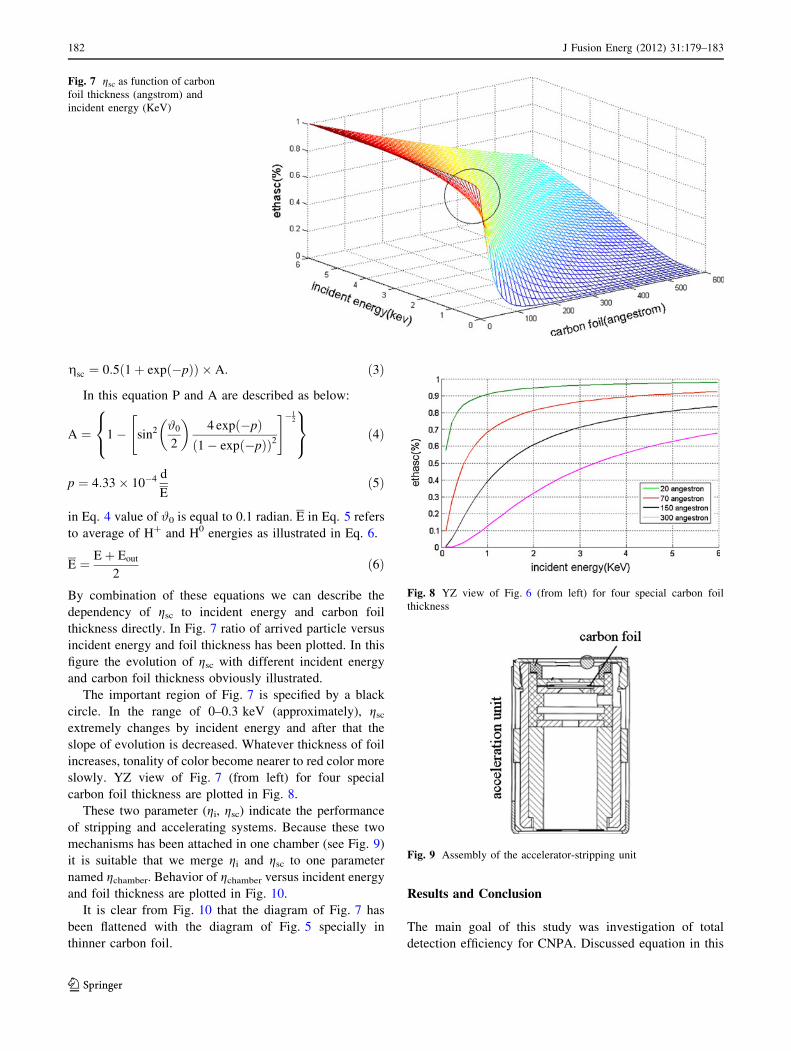
These two equations are plotted in Figs. 4 and 5 by
Fig. 1 A scheme of CNPA analyzer: (1) stripping and acceleration
system; (2) stripping foil; (3) bending magnet; (4) Hall probe; (5)
analyzing electrostatic condenser; (6) shielding mask; (7) detectors;
(A0) atomic flux emitted by plasma, (A?) secondary ions)
Fig. 2 Equilibrium fraction of hydrogen atom fragments that emerge
from a 300 A thick carbon foil
Fig. 3 Detection efficiency K(E) as a function of atom energy.
Equilibrium fraction of H?ions after stripping is simulated [6]
180 J Fusion Energ (2012) 31:179–183
123
MATLAB for special range of carbon foil thickness
(1–600 A) and incident energy of hydrogen beam (1 to
6 keV).
As it shown in Fig. 6, gi for 6 keV incident energy
equal to 0.09 in comparison with experimental result for
300 A0 in Fig. 2 is approximately 0.1.
Scattering Efficiency
The second parameter of total detection efficiency was
scattering of ion emerged from carbon foil (gsc). On the
other hand this factor describes the number of ions arriving
to the aperture of CNPA bending magnet. Because of
specific area of the aperture some particles scattered in
specific direction can affect by magnetic field of the device.
Value of gsc depend on E (hydrogen energy) and D (carbon
foil thickness) like gi. This dependency has been shown in
Eq. 3 [7].
Fig. 4 Variation of exit
hydrogen energy versus incident
energy and foil thickness after
passing through carbon foil
Fig. 5 Ratio of exit H? particle
after hydrogen beam passes
through carbon foil.
Approaching to high ratio of
exit H? particle needs to afford
thinner carbon foil as it
possible. Producing thinner
carbon foil needs more
technology and accurate
processing
Fig. 6 gi for 300 A0 carbon foil thickness versus incident energy
J Fusion Energ (2012) 31:179–183 181
123
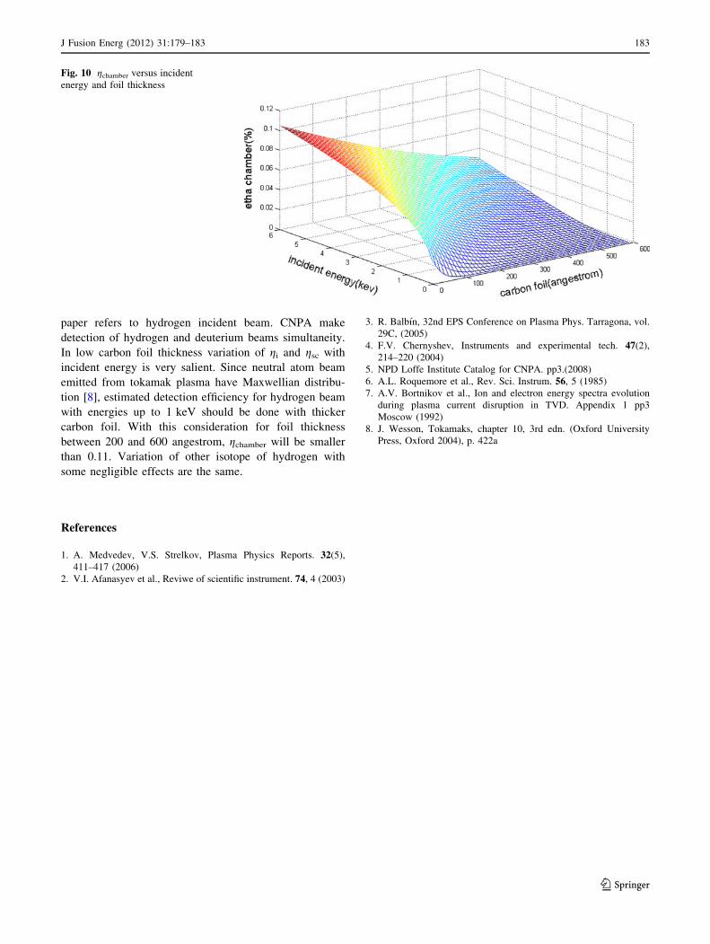
gsc ¼ 0:5 1þ exp �pð Þð Þ � A: ð3Þ
In this equation P and A are described as below:
A ¼ 1� sin2 #0
2
� �4 exp �pð Þ
1� exp �pð Þð Þ2
" #�12
8<
:
9=
;ð4Þ
p ¼ 4:33� 10�4 d
Eð5Þ
in Eq. 4 value of #0 is equal to 0.1 radian. E in Eq. 5 refers
to average of H? and H0 energies as illustrated in Eq. 6.
E ¼ Eþ Eout
2ð6Þ
By combination of these equations we can describe the
dependency of gsc to incident energy and carbon foil
thickness directly. In Fig. 7 ratio of arrived particle versus
incident energy and foil thickness has been plotted. In this
figure the evolution of gsc with different incident energy
and carbon foil thickness obviously illustrated.
The important region of Fig. 7 is specified by a black
circle. In the range of 0–0.3 keV (approximately), gsc
extremely changes by incident energy and after that the
slope of evolution is decreased. Whatever thickness of foil
increases, tonality of color become nearer to red color more
slowly. YZ view of Fig. 7 (from left) for four special
carbon foil thickness are plotted in Fig. 8.
These two parameter (gi, gsc) indicate the performance
of stripping and accelerating systems. Because these two
mechanisms has been attached in one chamber (see Fig. 9)
it is suitable that we merge gi and gsc to one parameter
named gchamber. Behavior of gchamber versus incident energy
and foil thickness are plotted in Fig. 10.
It is clear from Fig. 10 that the diagram of Fig. 7 has
been flattened with the diagram of Fig. 5 specially in
thinner carbon foil.
Results and Conclusion
The main goal of this study was investigation of total
detection efficiency for CNPA. Discussed equation in this
Fig. 7 gsc as function of carbon
foil thickness (angstrom) and
incident energy (KeV)
Fig. 8 YZ view of Fig. 6 (from left) for four special carbon foil
thickness
Fig. 9 Assembly of the accelerator-stripping unit
182 J Fusion Energ (2012) 31:179–183
123
paper refers to hydrogen incident beam. CNPA make
detection of hydrogen and deuterium beams simultaneity.
In low carbon foil thickness variation of gi and gsc with
incident energy is very salient. Since neutral atom beam
emitted from tokamak plasma have Maxwellian distribu-
tion [8], estimated detection efficiency for hydrogen beam
with energies up to 1 keV should be done with thicker
carbon foil. With this consideration for foil thickness
between 200 and 600 angestrom, gchamber will be smaller
than 0.11. Variation of other isotope of hydrogen with
some negligible effects are the same.
References
1. A. Medvedev, V.S. Strelkov, Plasma Physics Reports. 32(5),
411–417 (2006)
2. V.I. Afanasyev et al., Reviwe of scientific instrument. 74, 4 (2003)
3. R. Balbın, 32nd EPS Conference on Plasma Phys. Tarragona, vol.
29C, (2005)
4. F.V. Chernyshev, Instruments and experimental tech. 47(2),
214–220 (2004)
5. NPD Loffe Institute Catalog for CNPA. pp3.(2008)
6. A.L. Roquemore et al., Rev. Sci. Instrum. 56, 5 (1985)
7. A.V. Bortnikov et al., Ion and electron energy spectra evolution
during plasma current disruption in TVD. Appendix 1 pp3
Moscow (1992)
8. J. Wesson, Tokamaks, chapter 10, 3rd edn. (Oxford University
Press, Oxford 2004), p. 422a
Fig. 10 gchamber versus incident
energy and foil thickness
J Fusion Energ (2012) 31:179–183 183
123