Embed Size (px)
Citation preview
International Journal of Scientific & Engineering Research, Volume 5, Issue 12, December-2014 1596 ISSN 2229-5518
IJSER © 2014 http://www.ijser.org
EFFECT OF INJECTION TIMING ON PERFORMANCE PARAMETERS OF DIRECT
INJECTION DIESEL ENGINE WITH CERAMIC COATED CYLINDER HEAD
N. Janardhan1, M.V.S. Murali Krishna2*, Ch. Kesava Reddy3 and N.Durga Prasad4
1, 2Mechanical Engineering Department, Chaitanya Bharathi Institute of Technology, Gandipet, Hyderabad 500 075, Telangana State, India,
1E-mail: [email protected], 2E-mail:[email protected], 3Mechatronics Engineering Department, Mahatma Gandhi Institute Of Technology,
Gandipet, Hyderabad 500 075, Telangana State, India, 3E-mail: [email protected] 4Bharat Dynamics Limited, Hyderabad; 4E-mail: [email protected]
ABSTRACT Experiments were carried out to evaluate the performance of diesel engine with low heat rejection (LHR–1) combustion chamber consisting of conventional piston, conventional liner and ceramic coated cylinder head with neat diesel with varied injection timing. Performance parameters [brake thermal efficiency, exhaust gas temperature, coolant load, volumetric efficiency and sound levels ] were determined at various values of brake mean effective pressure (BMEP) of the engine with LHR–1 combustion chamber and compared with neat diesel operation on conventional engine (CE) at similar operating conditions. The optimum injection timing was found to be 31obTDC (before top dead centre) with conventional engine, while it was 30o bTDC for engine with LHR–1combustion chamber with diesel operation. Engine with LHR–1 combustion chamber with neat diesel operation showed comparable performance at manufacturer’s recommended injection timing of 27o bTDC, and the performance improved marginally with advanced injection timing of 30obTDC in comparison with CE at 27obTDC. Keywords: Conservation of diesel, conventional engine, LHR combustion chamber, Performance.
1.INTRODUCTION In the scenario of i) increase of vehicle population at an alarming rate due to advancement of civilization, ii) use of diesel fuel in not only transport sector but also in agriculture sector leading to fast depletion of diesel fuels and iii) increase of fuel prices in International market leading to burden on economic sector of Govt. of India, the conservation of diesel fuel has become pertinent for the engine manufacturers, users and researchers involved in the combustion research. [1]. The nation should pay gratitude towards Dr. Diesel for his remarkable invention of diesel engine. Compression ignition (CI) engines, due to their excellent fuel efficiency and durability, have become popular power plants for automotive applications. This is globally the most accepted type of internal combustion engine used for powering agricultural implements, industrial applications, and construction equipment along with marine propulsion. [2–3]. The concept of LHR combustion chamber is to reduce coolant losses by providing thermal resistance in the path of heat flow to the coolant, there by gaining thermal efficiency. Several methods adopted for achieving LHR to the coolant are ceramic coated engines and air gap insulated engines with creating air gap in the piston and other components with low-thermal conductivity materials like superni, cast iron and mild steel etc. LHR combustion chambers were classified as ceramic coated (LHR–1), air gap insulated (LHR–2) and combination of ceramic coated and air gap insulated engines(LHR-3) combustion chambers depending on degree of insulations. Experiments were conducted on engine with ceramic coated cylinder head with neat diesel operation at 27o bTDC and reported that brake specific fuel consumption (BSFC) increased by 2% in comparison with conventional engine.[4–6].
IJSER
International Journal of Scientific & Engineering Research, Volume 5, Issue 12, December-2014 1597 ISSN 2229-5518
IJSER © 2014 http://www.ijser.org
Hot combustion chamber was more suitable for burning high viscous vegetable oils. Investigations were carried out on single cylinder four-stroke water cooled diesel engine of 3.68 brake power at a speed of 1500 rpm at a compression ratio of 16:1 with engine with LHR–1 combustion chamber consisting of ceramic coated cylinder head with crude vegetable oils as alternative fuels with varied injection timing and pressure. [7–9]Engine with LHR-1 combustion chamber improved brake thermal efficiency by 4-6% with crude vegetable oils in comparison with CE with mineral diesel operation. Performance was further improved with an increase of injection pressure and advanced injection timing. Crude vegetable oils were converted to biodiesel by esterification in order to reduce viscosity and improve cetane value. Experiments were conducted on same configuration of the engine as specified in Ref [7–9] with biodiesel. Performance was improved with biodiesel operation with LHR-1 combustion chamber.[10–17] However, no systematic investigations were reported on comparative performance of the engine with LHR-1 combustion chamber with mineral diesel with varied injection timing The present paper attempted to evaluate the performance of LHR–1combustion chamber, which consisted of air conventional piston, conventional liner and ceramic coated cylinder head fuelled with diesel fuel with varied injection timing. Comparative performance studies were made on engine with LHR–1combustion chamber with conventional engine with diesel operation. 2.MATERIALS AND METHODS This part deals with fabrication of air gap insulated piston and air gap insulated liner, brief description of experimental set-up, specification of experimental engine, operating conditions and definitions of used values. The physic-chemical properties of the diesel fuel are presented in Table-1.
Table.1. Properties Of Diesel
Property Units Diesel Carbon chain -- C8-C28 Cetane Number 55 Density gm/cc 0.84 Bulk modulus @ 20Mpa
Mpa
1475
Kinematic viscosity @ 40oC
cSt
2.25
Sulfur % 0.25 Oxygen % 0.3 Air fuel ratio ( stochiometric)
-- 14.86
Lower calorific value
kJ/kg
44800
Flash point (Open cup)
oC
68 Molecular weight -- 226 Colour -- Light yellow
LHR-1 combustion chamber (Fig.1) contained cylinder head coated with partially stabilized zirconium (PSZ) of thickness 500 microns on inside portion of cylinder head. At 500oC the thermal conductivity of PSZ is 2.01 W/m-K. The test fuel used in the experimentation was neat diesel. The schematic diagram of the experimental setup with diesel operation is shown in Fig.1 The specifications of the experimental engine are shown in Table-2. Experimental setup used for study of exhaust emissions on low grade LHR diesel engine with cottonseed biodiesel in Fig.3 The specification of the experimental engine (Part No.1) is shown in Table.2 The engine was connected to an electric dynamometer (Part No.2. Kirloskar make) for measuring its brake power.
IJSER
International Journal of Scientific & Engineering Research, Volume 5, Issue 12, December-2014 1598 ISSN 2229-5518
IJSER © 2014 http://www.ijser.org
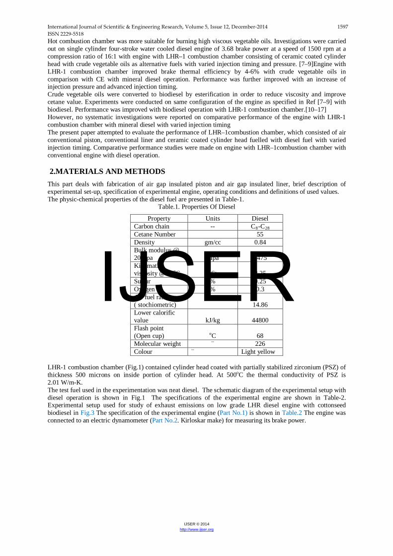
1.Engine, 2.Electical Dynamo meter, 3.Load Box, 4.Orifice meter, 5.U-tube water manometer, 6.Air box, 7.Fuel tank, 8, Three way valve, 9.Burette, 10. Exhaust gas temperature indicator, 11.AVL Smoke meter, 12.Netel Chromatograph NOx Analyzer, 13.Outlet jacket water temperature indicator and 14. Outlet-jacket water flow meter.
Fig.3. Schematic diagram of experimental set–up
Dynamometer was loaded by loading rheostat (Part No.3). The combustion chamber consisted of a direct injection type with no special arrangement for swirling motion of air. Burette (Part No.9) method was used for finding fuel consumption of the engine with the help of fuel tank (Part No7) and three way valve (Part No.8). Air-consumption of the engine was measured by air-box method consisting of an orifice meter (Part No.4), U-tube water manometer (Part No.5) and air box (Part No.6) assembly. The naturally aspirated engine was provided with water-cooling system in which outlet temperature of water is maintained at 80oC by adjusting the water flow rate. Engine oil was provided with a pressure feed system. No temperature control was incorporated, for measuring the lube oil temperature.
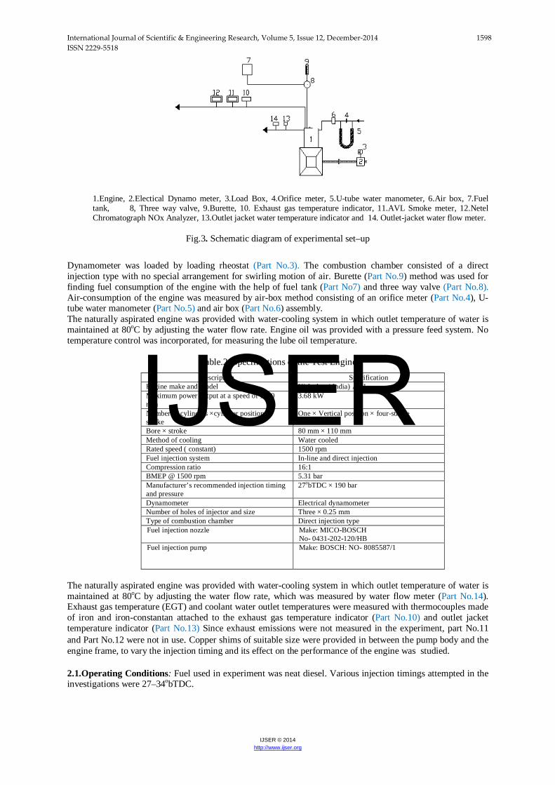
Table.2. Specifications of the Test Engine Description Specification
Engine make and model Kirloskar ( India) AV1 Maximum power output at a speed of 1500 rpm
3.68 kW
Number of cylinders ×cylinder position× stroke
One × Vertical position × four-stroke
Bore × stroke 80 mm × 110 mm Method of cooling Water cooled Rated speed ( constant) 1500 rpm Fuel injection system In-line and direct injection Compression ratio 16:1 BMEP @ 1500 rpm 5.31 bar Manufacturer’s recommended injection timing and pressure
27obTDC × 190 bar
Dynamometer Electrical dynamometer Number of holes of injector and size Three × 0.25 mm Type of combustion chamber Direct injection type Fuel injection nozzle Make: MICO-BOSCH
No- 0431-202-120/HB Fuel injection pump Make: BOSCH: NO- 8085587/1
The naturally aspirated engine was provided with water-cooling system in which outlet temperature of water is maintained at 80oC by adjusting the water flow rate, which was measured by water flow meter (Part No.14). Exhaust gas temperature (EGT) and coolant water outlet temperatures were measured with thermocouples made of iron and iron-constantan attached to the exhaust gas temperature indicator (Part No.10) and outlet jacket temperature indicator (Part No.13) Since exhaust emissions were not measured in the experiment, part No.11 and Part No.12 were not in use. Copper shims of suitable size were provided in between the pump body and the engine frame, to vary the injection timing and its effect on the performance of the engine was studied. 2.1.Operating Conditions: Fuel used in experiment was neat diesel. Various injection timings attempted in the investigations were 27–34obTDC.
IJSER
International Journal of Scientific & Engineering Research, Volume 5, Issue 12, December-2014 1599 ISSN 2229-5518
IJSER © 2014 http://www.ijser.org
2.2 Nomenclature ρa =density of air, kg/m3 ρd =density of fuel, gm/cc ηd =efficiency of dynamometer, 0.85 a= area of the orifice flow meter, m2 BP=brake power of the engine, kW Cd=coefficient of discharge, 0.65 Cp=specific heat of water in kJ/kg K D=bore of the cylinder, 80 mm d=diameter of the orifice flow meter, 20 mm DI=diesel injection I=ammeter reading, ampere H=difference of water level in U–tube water manometer in cm of water column K=number of cylinders, 01 L=stroke of the engine, 110 mm LHR-1= Insulated combustion chamber with ceramic coated cylinder head ma=mass of air inducted in engine, kg/h mf=mass of fuel, kg/h mw=mass flow rate of coolant, g/s n=power cycles per minute, N/2, N=speed of the engine, 1500 rpm Pa=atmosphere pressure in mm of mercury R=gas constant for air, 287 J/kg K T=time taken for collecting 10 cc of fuel, second Ta=room temperature, o C TI=inlet temperature of water, o C To=outlet temperature of water, oC V=voltmeter reading, volt Vs=stroke volume, m3
VE=Volumetric efficiency, % 2.3Definitions of used values: mf=
𝟏𝟎×ρ𝒅×𝟑𝟔𝟎𝟎
𝒕×𝟏𝟎𝟎𝟎—equation (1)
BP= 𝑽×𝑰
η𝒅×𝟏𝟎𝟎𝟎 equation (2)
BTE= 𝑩𝑷×𝟑𝟔𝟎𝟎
𝒎𝒇×𝑪𝑽 equation (3)
BP= 𝑩𝑴𝑬𝑷×𝟏𝟎𝟓×𝑳×𝑨×𝒏×𝒌
𝟔𝟎𝟎𝟎𝟎 ---equation (4)
CL= 𝒎𝒘 × 𝒄𝒑 × (𝑻𝒐 − 𝑻𝒊) equation (5) 𝒎𝒂 = 𝑪𝒅 × 𝒂 × �𝟐 × 𝟏𝟎 × 𝒈 × 𝒉× ρ𝒂 × 𝟑𝟔𝟎𝟎 (6)
𝒂 = π×𝒅𝟐
𝟒 equation (7)
η𝒗 = 𝒎𝒂×𝟐
𝟔𝟎×ρ𝒂×𝑵×𝑽𝒔 equation (8)
ρ𝒂 = 𝑷𝒂×𝟏𝟎𝟓
𝟕𝟓𝟎×𝑹×𝑻𝒂 equation (9)
3. RESULTS AND DICUSSION
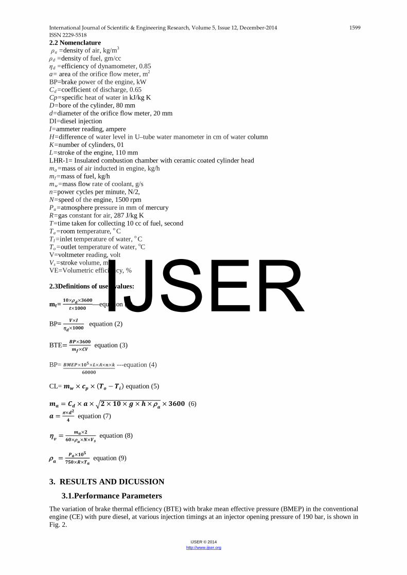
3.1.Performance Parameters The variation of brake thermal efficiency (BTE) with brake mean effective pressure (BMEP) in the conventional engine (CE) with pure diesel, at various injection timings at an injector opening pressure of 190 bar, is shown in Fig. 2.
IJSER
International Journal of Scientific & Engineering Research, Volume 5, Issue 12, December-2014 1600 ISSN 2229-5518
IJSER © 2014 http://www.ijser.org
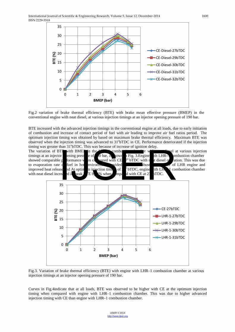
Fig.2 variation of brake thermal efficiency (BTE) with brake mean effective pressure (BMEP) in the conventional engine with neat diesel, at various injection timings at an injector opening pressure of 190 bar. BTE increased with the advanced injection timings in the conventional engine at all loads, due to early initiation of combustion and increase of contact period of fuel with air leading to improve air fuel ratios period. The optimum injection timing was obtained by based on maximum brake thermal efficiency. Maximum BTE was observed when the injection timing was advanced to 31obTDC in CE. Performance deteriorated if the injection timing was greater than 31obTDC. This was because of increase of ignition delay. The variation of BTE with BMEP in the LHR–1 combustion chamber with neat diesel at various injection timings at an injector opening pressure of 190 bar, is shown in Fig. 3.Engine with LHR–1 combustion chamber showed comparable performance when compared with CE 27o bTDC with neat diesel operation. This was due to evaporation rate of fuel in hot environment provided by hot combustion chamber of LHR engine and improved heat release and At optimum injection timing of 30o bTDC, engine with LHR–1 combustion chamber with neat diesel increased its peak BTE by 4% when compared with CE at 27o bTDC.
Fig.3. Variation of brake thermal efficiency (BTE) with engine with LHR–1 combustion chamber at various injection timings at an injector opening pressure of 190 bar. Curves in Fig.4indicate that at all loads, BTE was observed to be higher with CE at the optimum injection timing when compared with engine with LHR–1 combustion chamber. This was due to higher advanced injection timing with CE than engine with LHR–1 combustion chamber.
0
5
10
15
20
25
30
35
0 1 2 3 4 5 6
BTE
(%)
BMEP (bar)
CE-Diesel-27bTDC
CE-Diesel-29bTDC
CE-Diesel-30bTDC
CE-Diesel-31bTDC
CE-Diesel-32bTDC
0
5
10
15
20
25
30
35
0 1 2 3 4 5 6
BTE
(%)
BMEP (bar)
CE-27bTDC
LHR-1-27bTDC
LHR-1-29bTDC
LHR-1-30bTDC
LHR-1-31bTDC
IJSER

International Journal of Scientific & Engineering Research, Volume 5, Issue 12, December-2014 1601 ISSN 2229-5518
IJSER © 2014 http://www.ijser.org
Fig.4Variation of brake thermal efficiency with brake mean effective pressure effective pressure (BMEP) with conventional engine (CE) and engine with LHR–1 combustion chamber at recommended injection timing and optimum injection timing. Fig.5 shows that engine with LHR–1combustion chamber increased peak BTE by 2% at 27obTDC, while decreasing it by 8% at 30obTDC when compared with CE at 27obTDC and 31obTDC.
Fig.5. Bar charts showing the variation of peak brake thermal efficiency (%) with conventional engine (CE) and engine with LHR–1 combustion chamber at recommended injection timing and optimized injection timing. When engine with different versions of the combustion chamber is to be tested, then brake specific fuel consumption (BSFC) at full load is to be determined in order to compare the performance of the engine.Fig.6 indicates that engine with LHR-1 combustion chamber increased BSFC at full load operation by 2% at 27obTDC and 8% at 30obTDC when compared with CE at 27obTDC and 31obTDC. This was due reduction of ignition delay with engine with LHR-1 combustion chamber and higher injection advance with CE.
0
5
10
15
20
25
30
35
0 1 2 3 4 5 6
BTE
(%)
BMEP (bar)
CE-27bTDC
LHR-1-27bTDC
CE-31bTDC
LHR-1-30bTDC
27 27.5 28 28.5 29 29.5 30 30.5 31
1
Peak BTE (%)
LHR-1-30bTDC
CE-31bTDC
LHR-1-27bTDC
CE-27bTDC
IJSER
International Journal of Scientific & Engineering Research, Volume 5, Issue 12, December-2014 1602 ISSN 2229-5518
IJSER © 2014 http://www.ijser.org
Fig.6. Bar charts showing the variation of brake specific fuel consumption (BSFC) at full load operation with conventional engine (CE) and engine with LHR–1 combustion chamber at recommended injection timing and optimized injection timing.
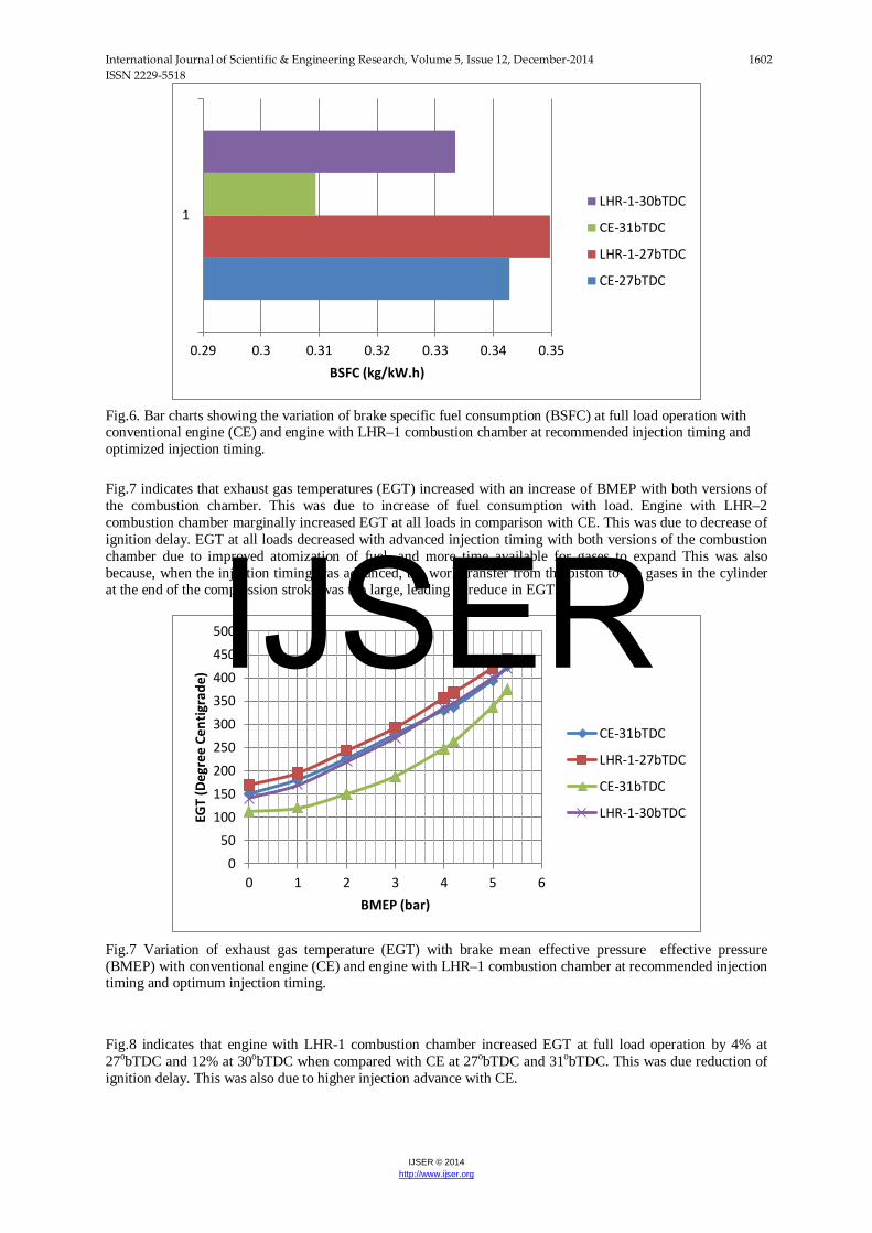
Fig.7 indicates that exhaust gas temperatures (EGT) increased with an increase of BMEP with both versions of the combustion chamber. This was due to increase of fuel consumption with load. Engine with LHR–2 combustion chamber marginally increased EGT at all loads in comparison with CE. This was due to decrease of ignition delay. EGT at all loads decreased with advanced injection timing with both versions of the combustion chamber due to improved atomization of fuel, and more time available for gases to expand This was also because, when the injection timing was advanced, the work transfer from the piston to the gases in the cylinder at the end of the compression stroke was too large, leading to reduce in EGT.
Fig.7 Variation of exhaust gas temperature (EGT) with brake mean effective pressure effective pressure (BMEP) with conventional engine (CE) and engine with LHR–1 combustion chamber at recommended injection timing and optimum injection timing. Fig.8 indicates that engine with LHR-1 combustion chamber increased EGT at full load operation by 4% at 27obTDC and 12% at 30obTDC when compared with CE at 27obTDC and 31obTDC. This was due reduction of ignition delay. This was also due to higher injection advance with CE.
0.29 0.3 0.31 0.32 0.33 0.34 0.35
1
BSFC (kg/kW.h)
LHR-1-30bTDC
CE-31bTDC
LHR-1-27bTDC
CE-27bTDC
050
100150200250300350400450500
0 1 2 3 4 5 6
EGT
(Deg
ree
Cent
igra
de)
BMEP (bar)
CE-31bTDC
LHR-1-27bTDC
CE-31bTDC
LHR-1-30bTDC
IJSER
International Journal of Scientific & Engineering Research, Volume 5, Issue 12, December-2014 1603 ISSN 2229-5518
IJSER © 2014 http://www.ijser.org
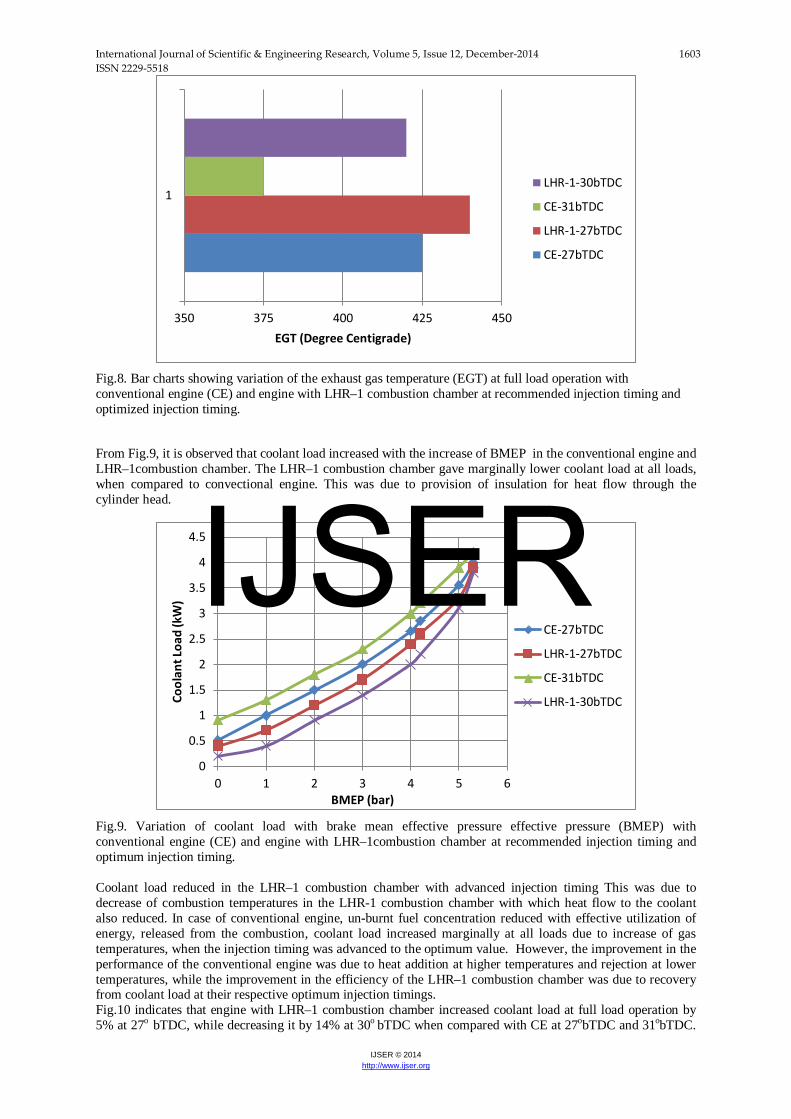
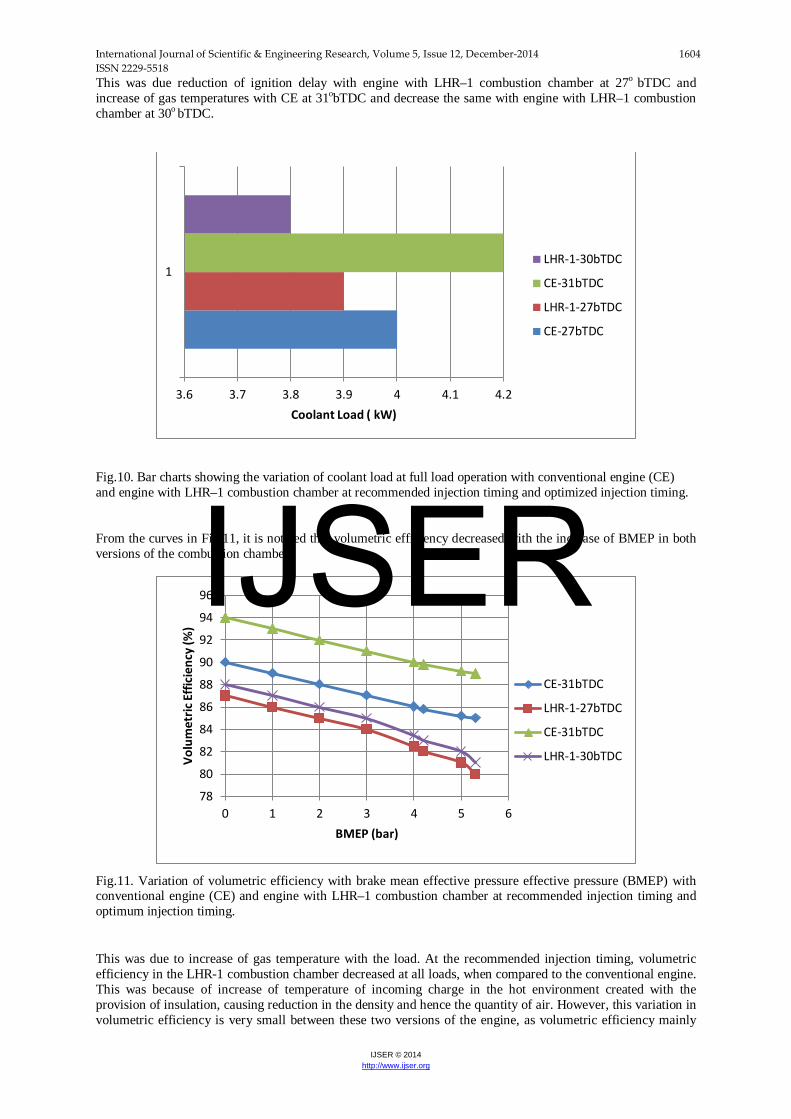
Fig.8. Bar charts showing variation of the exhaust gas temperature (EGT) at full load operation with conventional engine (CE) and engine with LHR–1 combustion chamber at recommended injection timing and optimized injection timing. From Fig.9, it is observed that coolant load increased with the increase of BMEP in the conventional engine and LHR–1combustion chamber. The LHR–1 combustion chamber gave marginally lower coolant load at all loads, when compared to convectional engine. This was due to provision of insulation for heat flow through the cylinder head.
Fig.9. Variation of coolant load with brake mean effective pressure effective pressure (BMEP) with conventional engine (CE) and engine with LHR–1combustion chamber at recommended injection timing and optimum injection timing. Coolant load reduced in the LHR–1 combustion chamber with advanced injection timing This was due to decrease of combustion temperatures in the LHR-1 combustion chamber with which heat flow to the coolant also reduced. In case of conventional engine, un-burnt fuel concentration reduced with effective utilization of energy, released from the combustion, coolant load increased marginally at all loads due to increase of gas temperatures, when the injection timing was advanced to the optimum value. However, the improvement in the performance of the conventional engine was due to heat addition at higher temperatures and rejection at lower temperatures, while the improvement in the efficiency of the LHR–1 combustion chamber was due to recovery from coolant load at their respective optimum injection timings. Fig.10 indicates that engine with LHR–1 combustion chamber increased coolant load at full load operation by 5% at 27o bTDC, while decreasing it by 14% at 30o bTDC when compared with CE at 27obTDC and 31obTDC.
350 375 400 425 450
1
EGT (Degree Centigrade)
LHR-1-30bTDC
CE-31bTDC
LHR-1-27bTDC
CE-27bTDC
0
0.5
1
1.5
2
2.5
3
3.5
4
4.5
0 1 2 3 4 5 6
Cool
ant L
oad
(kW
)
BMEP (bar)
CE-27bTDC
LHR-1-27bTDC
CE-31bTDC
LHR-1-30bTDC
IJSER
International Journal of Scientific & Engineering Research, Volume 5, Issue 12, December-2014 1604 ISSN 2229-5518
IJSER © 2014 http://www.ijser.org
This was due reduction of ignition delay with engine with LHR–1 combustion chamber at 27o bTDC and increase of gas temperatures with CE at 31obTDC and decrease the same with engine with LHR–1 combustion chamber at 30o bTDC.
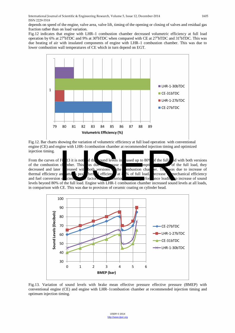
Fig.10. Bar charts showing the variation of coolant load at full load operation with conventional engine (CE) and engine with LHR–1 combustion chamber at recommended injection timing and optimized injection timing. From the curves in Fig.11, it is noticed that volumetric efficiency decreased with the increase of BMEP in both versions of the combustion chamber.
Fig.11. Variation of volumetric efficiency with brake mean effective pressure effective pressure (BMEP) with conventional engine (CE) and engine with LHR–1 combustion chamber at recommended injection timing and optimum injection timing. This was due to increase of gas temperature with the load. At the recommended injection timing, volumetric efficiency in the LHR-1 combustion chamber decreased at all loads, when compared to the conventional engine. This was because of increase of temperature of incoming charge in the hot environment created with the provision of insulation, causing reduction in the density and hence the quantity of air. However, this variation in volumetric efficiency is very small between these two versions of the engine, as volumetric efficiency mainly
3.6 3.7 3.8 3.9 4 4.1 4.2
1
Coolant Load ( kW)
LHR-1-30bTDC
CE-31bTDC
LHR-1-27bTDC
CE-27bTDC
78
80
82
84
86
88
90
92
94
96
0 1 2 3 4 5 6
Volu
met
ric E
ffici
ency
(%)
BMEP (bar)
CE-31bTDC
LHR-1-27bTDC
CE-31bTDC
LHR-1-30bTDC
IJSER
International Journal of Scientific & Engineering Research, Volume 5, Issue 12, December-2014 1605 ISSN 2229-5518
IJSER © 2014 http://www.ijser.org
depends on speed of the engine, valve area, valve lift, timing of the opening or closing of valves and residual gas fraction rather than on load variation. Fig.12 indicates that engine with LHR–1 combustion chamber decreased volumetric efficiency at full load operation by 6% at 27obTDC and 9% at 30obTDC when compared with CE at 27obTDC and 31obTDC. This was due heating of air with insulated components of engine with LHR–1 combustion chamber. This was due to lower combustion wall temperatures of CE which in turn depend on EGT.
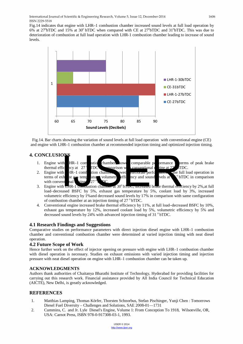
Fig.12. Bar charts showing the variation of volumetric efficiency at full load operation with conventional engine (CE) and engine with LHR–1combustion chamber at recommended injection timing and optimized injection timing. From the curves of Fig.13 it is noticed that sound levels increased up to 80% of the full load with both versions of the combustion chamber. This was due to increase of fuel consumption. At 80% of the full load, they decreased and later increased with both versions of the combustion chamber. This was due to increase of thermal efficiency and attains peak thermal efficiency at 80% of full load. Decrease of mechanical efficiency and fuel conversion efficiency were factors which deteriorate engine performance leading to increase of sound levels beyond 80% of the full load. Engine with LHR-1 combustion chamber increased sound levels at all loads, in comparison with CE. This was due to provision of ceramic coating on cylinder head.
Fig.13. Variation of sound levels with brake mean effective pressure effective pressure (BMEP) with conventional engine (CE) and engine with LHR–1combustion chamber at recommended injection timing and optimum injection timing.
79 80 81 82 83 84 85 86 87 88 89
1
Volumetric Efficiency (%)
LHR-1-30bTDC
CE-31bTDC
LHR-1-27bTDC
CE-27bTDC
30
40
50
60
70
80
90
100
0 1 2 3 4 5 6
Soun
d Le
vels
(Dec
ibel
s)
BMEP (bar)
CE-27bTDC
LHR-1-27bTDC
CE-31bTDC
LHR-1-30bTDC
IJSER
International Journal of Scientific & Engineering Research, Volume 5, Issue 12, December-2014 1606 ISSN 2229-5518
IJSER © 2014 http://www.ijser.org
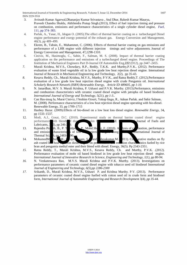
Fig.14 indicates that engine with LHR–1 combustion chamber increased sound levels at full load operation by 6% at 27obTDC and 15% at 30o bTDC when compared with CE at 27obTDC and 31obTDC. This was due to deterioration of combustion at full load operation with LHR-1 combustion chamber leading to increase of sound levels.
Fig.14. Bar charts showing the variation of sound levels at full load operation with conventional engine (CE)
and engine with LHR–1 combustion chamber at recommended injection timing and optimized injection timing.
4. CONCLUSIONS 1. Engine with LHR–1 combustion chamber showed comparable performance in terms of peak brake
thermal efficiency at 27 o bTDC in comparison with conventional engine at 27 o bTDC. 2. Engine with LHR–1 combustion chamber showed deteriorate performance at the full load operation in
terms of exhaust gas temperature, volumetric efficiency and sound levels at 27 o bTDC in comparison with conventional engine at 27 o bTDC.
3. Engine with LHR-1 combustion chamber at 30o bTDC, increased brake thermal efficiency by 2%,at full load–decreased BSFC by 5%, exhaust gas temperature by 5%, coolant load by 3%, increased volumetric efficiency by 1%and decreased sound levels by 17% in comparison with same configuration of combustion chamber at an injection timing of 27 o bTDC.
4. Conventional engine increased brake thermal efficiency by 11%, at full load–decreased BSFC by 10%, exhaust gas temperature by 12%, increased coolant load by 5%, volumetric efficiency by 5% and decreased sound levels by 24% with advanced injection timing of 31 o bTDC.
4.1 Research Findings and Suggestions Comparative studies on performance parameters with direct injection diesel engine with LHR–1 combustion chamber and conventional combustion chamber were determined at varied injection timing with neat diesel operation. 4.2 Future Scope of Work Hence further work on the effect of injector opening on pressure with engine with LHR–1 combustion chamber with diesel operation is necessary. Studies on exhaust emissions with varied injection timing and injection pressure with neat diesel operation on engine with LHR–1 combustion chamber can be taken up. ACKNOWLEDGMENTS Authors thank authorities of Chaitanya Bharathi Institute of Technology, Hyderabad for providing facilities for carrying out this research work. Financial assistance provided by All India Council for Technical Education (AICTE), New Delhi, is greatly acknowledged. REFERENCES 1. Matthias Lamping, Thomas Körfer, Thorsten Schnorbus, Stefan Pischinger, Yunji Chen : Tomorrows
Diesel Fuel Diversity – Challenges and Solutions, SAE 2008-01—1731 2. Cummins, C. and Jr. Lyle Diesel's Engine, Volume 1: From Conception To 1918, Wilsonville, OR,
USA: Carnot Press, ISBN 978-0-917308-03-1, 1993.
60 65 70 75 80 85 90
1
Sound Levels (Decibels)
LHR-1-30bTDC
CE-31bTDC
LHR-1-27bTDC
CE-27bTDC
IJSER
International Journal of Scientific & Engineering Research, Volume 5, Issue 12, December-2014 1607 ISSN 2229-5518
IJSER © 2014 http://www.ijser.org
3. Avinash Kumar Agarwal,Dhananjay Kumar Srivastava , Atul Dhar, Rakesh Kumar Maurya, Pravesh Chandra Shukla, Akhilendra Pratap Singh.(2013), Effect of fuel injection timing and pressure on combustion, emissions and performance characteristics of a single cylinder diesel engine, Fuel, 111, pp 374–383.
4. Parlak, A., Yasar, H., ldogan O. (2005).The effect of thermal barrier coating on a turbocharged Diesel engine performance and exergy potential of the exhaust gas. Energy Conversion and Management, 46(3), pp 489–499.
5. Ekrem, B., Tahsin, E., Muhammet, C. (2006). Effects of thermal barrier coating on gas emissions and performance of a LHR engine with different injection timings and valve adjustments. Journal of Energy Conversion and Management, 47,1298-1310.
6. Ciniviz, M., Hasimoglu, C., Sahin, F., Salman, M. S. (2008). Impact of thermal barrier coating application on the performance and emissions of a turbocharged diesel engine. Proceedings of The Institution of Mechanical Engineers Part D-Journal Of Automobile Eng,222 (D12), pp 2447–2455.
7. Murali Krishna, M.V.S., Chowdary, R.P., Reddy, T.K.K. and Murthy,P.V.K.. (2012). Performance evaluation of waste fried vegetable oil in la low grade low heat rejection diesel engine. International Journal of Research in Mechanical Engineering and Technology, 2(2), pp 35-43.
8. Kesava Reddy, Ch., Murali Krishna, M.V.S., Murthy, P.V.K., and Ratna Reddy,T. (2012).Performance evaluation of a low grade low heat rejection diesel engine with crude Pongamia oil. International Scholarly Research Network (ISRN) Renewable Energy, Article ID 489605, pp 1-10.
9. N. Janardhan, M.V. S. Murali Krishna, P. Ushasri and P.V.K. Murthy. (2013).Performance, emissions and combustion characteristics with ceramic coated diesel engine with jatropha oil based biodiesel. International Journal of Energy and Technology, 5(21), pp 1-3..
10. Can Has-imog lu, Murat Ciniviz, I˙brahim Ozsert, Yakup Iingu, R., Adnan Parlak. and Sahir Salman, M. (2008). Performance characteristics of a low heat rejection diesel engine operating with bio-diesel. Renewable Energy, 33, pp 1709–1715
11. Hanbey Hazar. (2009).Effects of bio-diesel on a low heat loss diesel engine. Renewable Energy, 34, pp 1533–1537.
12. Modi, A.J., Gosai, D.C. (2010). Experimental study on thermal barrier coated diesel engine performance with blends of diesel and palm bio-diesel. SAE International Journal of Fuels and Lubricants, 3 (2), pp 246-259.
13. Rajendra Prasath, B., P. Tamilporai ,P., Mohd.Shabir, F. (2010). Analysis of combustion, performance and emission characteristics of low heat rejection engine using biodiesel. International Journal of Thermal Sci, 49, pp 2483-2490.
14. MohamedMusthafa, M., Sivapirakasam, S.P. and Udayakumar.M. (2011). Comparative studies on fly ash coated low heat rejection diesel engine on performance and emission characteristics fueled by rice bran and pongamia methyl ester and their blend with diesel. Energy, 36(5). Pp 2343-2351.
15. Ratna Reddy, T., Murali Krishna, M.V.S., Kesava Reddy, Ch. and Murthy, P.V.K. .(2012). Performance evaluation of mohr oil based biodiesel in low grade low heat rejection diesel engine. International Journal of Innovative Research in Science, Engineering and Technology, 1(1), pp 80-94.
16. N. Venkateswara Rao, M.V.S. Murali Krishna and P.V.K. Murthy. (2013). Investigations on performance parameters of ceramic coated diesel engine with tobacco seed oil biodiesel International Journal of Engineering and Technology, 6(5),pp 2286-2300
17. Srikanth, D., Murali Krishna, M.V.S., Ushasri P. and Krishna Murthy. P.V. (2013). Performance parameters of ceramic coated diesel engine fuelled with cotton seed oil in crude form and biodiesel form, International Journal of Automobile Engineering and Research Development 3(4), pp 35-44.
IJSER