Embed Size (px)
Citation preview

EFFECT OF MICROSTRUCTURE ON PLAIN STRAIN FRACTURE TOUGHNESS
OF CARBON STEEL
MUHAMAD HANIF BIN MUHAMAD
Report submitted in fulfillment of the requirements
for the award of the degree of
Bachelor of Mechanical Engineering
Faculty of Mechanical Engineering
UNIVERSITI MALAYSIA PAHANG
JUNE 2012
vii
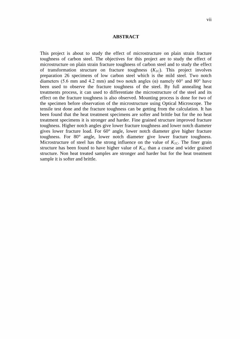
ABSTRACT
This project is about to study the effect of microstructure on plain strain fracture
toughness of carbon steel. The objectives for this project are to study the effect of
microstructure on plain strain fracture toughness of carbon steel and to study the effect
of transformation structure on fracture toughness (K1C). This project involves
preparation 26 specimens of low carbon steel which is the mild steel. Two notch
diameters (5.6 mm and 4.2 mm) and two notch angles (α) namely 60° and 80° have
been used to observe the fracture toughness of the steel. By full annealing heat
treatments process, it can used to differentiate the microstructure of the steel and its
effect on the fracture toughness is also observed. Mounting process is done for two of
the specimen before observation of the microstructure using Optical Microscope. The
tensile test done and the fracture toughness can be getting from the calculation. It has
been found that the heat treatment specimens are softer and brittle but for the no heat
treatment specimens it is stronger and harder. Fine grained structure improved fracture
toughness. Higher notch angles give lower fracture toughness and lower notch diameter
gives lower fracture load. For 60° angle, lower notch diameter give higher fracture
toughness. For 80° angle, lower notch diameter give lower fracture toughness.
Microstructure of steel has the strong influence on the value of K1C. The finer grain
structure has been found to have higher value of K1C than a coarse and wider grained
structure. Non heat treated samples are stronger and harder but for the heat treatment
sample it is softer and brittle.

viii
ABSTRAK
Projek ini adalah untuk mengkaji kesan mikrostruktur pada terikan mudah, kekuatan
patah keluli karbon. Objektif bagi projek ini adalah untuk mengkaji kesan mikrostruktur
pada terikan mudah, kekuatan patah keluli karbon dan untuk mengkaji kesan
transformasi struktur pada keliatan patah (K1C). Projek ini melibatkan penyediaan 26
spesimen keluli karbon rendah iaitu keluli lembut. Dua takuk diameter (5.6 mm and 4.2
mm) dan dua sudut takuk (α) iaitu 60 ° dan 80 ° telah digunakan untuk memerhatikan
keliatan patah keluli. Mengikut proses rawatan haba penuh penyepuhlindapan, ia boleh
digunakan untuk membezakan mikrostruktur keluli dan kesannya terhadap keliatan
patah juga diperhatikan. Proses mounting dilakukan kepada dua spesimen sebelum
pemerhatian mikrostruktur menggunakan Mikroskop Optik. Ujian tegangan dilakukan
dan keliatan patah boleh didapati melalui pengiraan. Keputusan didapati bahawa
spesimen rawatan haba adalah lebih lembut dan rapuh tetapi untuk spesimen tiada
rawatan haba ia lebih kuat dan lebih keras. struktur berbutir kecil meninggikan kekuatan
patah. Sudut takuk yang lebih tinggi memberikan kekuatan patah yang lebih rendah dan
diameter takuk yang lebih rendah memberi bebanan patah yang lebih rendah. Untuk
sudut 60°, takuk yang lebih rendah diameter memberi kekuatan patah yang lebih tinggi.
Untuk sudut 80°, takuk yang lebih rendah diameter memberi kekuatan patah yang lebih
rendah. Mikrostruktur keluli mempunyai pengaruh yang kuat ke atas nilai K1C. Struktur
bijian halus telah didapati mempunyai nilai yang lebih tinggi K1C daripada struktur
berbutir kasar dan lebih luas. Sampel tiada rawatan haba lebih kuat dan lebih keras
tetapi untuk sampel rawatan haba ia lebih lembut dan rapuh.

ix
TABLE OF CONTENTS
Page
EXAMINER’S DECLARATION ii
SUPERVISOR’S DECLARATION iii
STUDENT’S DECLARATION iv
DEDICATIONS v
ACKNOWLEDGEMENTS vi
ABSTRACT vii
ABSTRAK viii
TABLE OF CONTENTS ix
LIST OF TABLES xii
LIST OF FIGURES xiii
LIST OF SYMBOLS xv
LIST OF ABBREVIATIONS xvii
CHAPTER 1 INTRODUCTION
1.1 Project background 1
1.2 Problem statement 2
1.3 Objective 2
1.4 Project scope 3
CHAPTER 2 LITERATURE REVIEW
2.1 Introduction 4
2.2 Microstructure 4
2.2.1 Microstructural analysis 6
2.2.2 Metallography 7
2.3 Plain strain 8
2.4 Fracture toughness 10
2.5 Carbon steel 12

x
CHAPTER 3 METHODOLOGY
3.1 Introduction 15
3.2 Flow chart methodology 15
3.3 Procedure 17
3.4 Design of experiment 18
3.4.1 Specimens preparation 18
3.4.1.1 Material 20
3.4.1.2 Machining 21
3.4.2 Heat treatment 29
3.4.3 Microstructure checking using optical microscope 31
3.4.4 Tensile test 32
CHAPTER 4 RESULT AND DISCUSSION
4.1 Introduction 33
4.2 Material composition 34
4.3 Microstructure investigation 35
4.3.1 Mild steel with no heat treatment process 35
4.3.2 Mild steel with heat treatment process 37
4.4 Tensile test properties 38
4.4.1 Fracture toughness (K1C) calculation for notch
diameter (d): 5.6 mm, heat treatment, notch angle
60°
40
4.4.2 Fracture toughness (K1C) calculation for notch
diameter (d): 5.6 mm, without heat treatment, notch
angle 60°
42
4.4.3 Fracture toughness (K1C) calculation for notch
diameter (d): 5.6 mm, heat treatment, notch angle
80°
43
4.4.4 Fracture toughness (K1C) calculation for notch
diameter (d): 5.6 mm, without heat treatment, notch
angle 80°
44
4.4.5 Fracture toughness (K1C) calculation for notch
diameter (d): 4.2 mm, heat treatment, notch angle
60°
45
4.4.6 Fracture toughness (K1C) calculation for notch
diameter (d): 4.2 mm, without heat treatment, notch
angle 60°
46

xi
4.4.7 Fracture toughness (K1C) calculation for notch
diameter (d): 4.2 mm, heat treatment, notch angle
80°
47
4.4.8 Fracture toughness (K1C) calculation for notch
diameter (d): 4.2 mm, without heat treatment, notch
angle 80°
48
4.5 Role of microstructure 49
4.6 Role of notch diameter and notch angle 50
CHAPTER 5 CONCLUSION
5.1 Introduction 51
5.2 Conclusion 51
5.3 Recommendations 52
5.3.1 Machining process 52
5.3.2 Future works 53
REFERENCES 54
APPENDICES
A Project Planning (Gantt Chart) 56

xii
LIST OF TABLES
Table No. Title Page
2.1 Room-temperature plain strain fracture toughness values 12
2.2 Properties of plain carbon steel 14
3.1 Chemical composition of steel used, wt% 21
3.2 Table for selection of cutting speed for mild steel 22
3.3 Table for selection of feed based on material 23
3.4 Specimen quantity for experiment 26
4.1 Chemical composition of the specimens 34
4.2 Fracture load and fracture toughness for every specimen condition 38
4.3 Result of fracture load (Pf) for notch diameter (d) 5.6 mm, heat
treatment, notch angle 60° 41
4.4 Result of fracture load (Pf) for notch diameter (d) 5.6 mm,
without heat treatment, notch angle 60° 42
4.5 Result of fracture load (Pf) for notch diameter (d) 5.6 mm, heat
treatment, notch angle 80° 43
4.6 Result of fracture load (Pf) for notch diameter (d) 5.6 mm,
without heat treatment, notch angle 80° 44
4.7 Result of fracture load (Pf) for notch diameter (d) 4.2 mm, heat
treatment, notch angle 60° 45
4.8 Result of fracture load (Pf) for notch diameter (d) 4.2 mm,
without heat treatment, notch angle 60° 46
4.9 Result of fracture load (Pf) for notch diameter (d) 4.2 mm, heat
treatment, notch angle 80° 47
4.10 Result of fracture load (Pf) for notch diameter (d) 4.2 mm,
without heat treatment, notch angle 80° 48

xiii
LIST OF FIGURES
Figure No. Title Page
2.1 Notational conventions in-plane strain of a thin plate in plane
stress 8
2.2 Cam plastometer flow-stress measurements for a plain carbon
steel:strain rate (a) = 2s-1;(b) = 20s-1; (c) = 120s-1 9
2.3 Stress strain diagram 11
3.1 Overall flowchart 16
3.2 Methodology flowchart 17
3.3 Schematic representation of round notched tensile specimen 19
3.4 Raw material before machining 20
3.5 Conventional lathe machine ERL-1340 LATHE (ERL series) 25
3.6 Turning process 25
3.7 Workpiece (7 mm) 26
3.8 Tool for 60° notch 27
3.9 Tool for 80° notch 28
3.10 Specimens after notching process 28
3.11 Specimens after full annealing 30
3.12 ThermoConcept furnace 30
3.13 Optical microscope 31
3.14 Instron tensile test machine 32
4.1 The microstructure under 100X magnification 36
4.2 The microstructure under 200X magnification 36
4.3 The microstructure under 200X magnification 37
4.4 Variation of fracture toughness with notch angle of heat treatment
samples 39

xiv
4.5 Variation of fracture toughness with notch angle of no heat
treatment samples 40
4.6 Graph load vs extension for three specimen for notch diameter (d)
5.6 mm, heat treatment, notch angle 60° 40
4.7 Graph load vs extension for three specimen for notch diameter (d)
5.6 mm, without heat treatment, notch angle 60° 42
4.8 Graph load vs extension for three specimen for notch diameter (d)
5.6 mm, heat treatment, notch angle 80° 43
4.9 Graph load vs extension for three specimen for notch diameter (d)
5.6 mm, without heat treatment, notch angle 80° 44
4.10 Graph load vs extension for three specimen for notch diameter (d)
4.2 mm, heat treatment, notch angle 60° 45
4.11 Graph load vs extension for two specimen for notch diameter (d)
4.2 mm, without heat treatment, notch angle 60° 46
4.12 Graph load vs extension for two specimen for notch diameter (d)
4.2 mm, heat treatment, notch angle 80° 47
4.13 Graph load vs extension for two specimen for notch diameter (d)
4.2 mm, without heat treatment, notch angle 80° 48

xv
LIST OF SYMBOLS
mm Millimeter
MPa Mega Pascal
% Percent
kN Kilo newton
K1C Fracture toughness
° Degree
D Total diameter
Fe Iron
C Carbon
Mn Manganese
S Sulphur
Si Silicone
d Notch diameter
α Notch angles
o C Degree Celsius
Cr Cromium
Mo Molybdenum
m Meter
Ni Nickel
Ti-6A1-4V Titanium Alloy
Sn Stannum
rpm Revolution per minutes
min minutes

xvi
N Spindle speed
CS Cutting speed
d Diameter of raw material
f feed
vf Feed rate
do Diameter of raw material initial
df Diameter of raw materil final
rev Revolution
Pf Fracture load
Fe3C Cementite
CCRB Circumferentially cracked round bar
CNC Computer numeric control

xvii
LIST OF ABBREVIATIONS
ASTM American Society for Testing and Materials
ASME American Society of Mechanical Engineers
MS Malaysian Standard
AISI American iron and steel institute
CT Compact tension
ANSI American National Standards Institute
SENB Single edge notch bending
UTM Universal testing machine
PMMA Polymethyl methacrylate
PS Polystyrene

CHAPTER 1
INTRODUCTION
1.1 PROJECT BACKGROUND
The measure of resistance to crack propagation is termed as fracture toughness
(Dieter, 1988). In general machine components and structural components are designed
over sized in order to avoid failure. This leads to consumption of more material and
over weight problem. Hence such efforts are not cost effective. This problem is
basically due to non availability of fracture toughness data to the design engineers. In
view of this fracture toughness data are very useful in designing machine and structural
components which are safe but not over sized and overweight.
Fracture toughness is measured in terms of K1C (plane-strain fracture toughness)
where K stands for stress intensity factor at the crack tip, I- denotes that the fracture
toughness test is performed in tensile mode and C-denotes that the value of K is critical.
When K attains critical value then crack propagation becomes unstable and results in
fracture of the components. K1C is a basic material property like yield strength. For low
strength and high ductility materials like low carbon steels which find wide applications
in the making of pipes for nuclear power plants (Knott, 1979), J1C (J-integral) is
determined instead of K1C due to heavy amount of plastic deformation at the crack tip.
In such cases K1C is not a valid data (Dieter, 1988; Wei et al., 1982).

2
K1C is normally determined by using compact-tension (CT) specimen or single
edge notch bend (SENB) or three-point loaded bend specimens which are standardized
by ASTM (Dieter, 1988). In these techniques, specimen preparations and test are quite
tedious and time consuming. K1C determination by round notched tensile specimen is
quick and tensile test can be used instead of universal testing machine (UTM). It can
also be used in preliminary selection of fracture tough materials from a vast lot.
Another advantage of such specimen is their radial symmetry, which makes
them particularly suitable for studying the impact of the microstructure on fracture
toughness of steel. Namely, due to the radial symmetry of heat transfer, the formation of
a microstructure along the circumferential area is completely uniform. Further, this
method also has significance in measuring the fracture toughness of hard and brittle
alloys, since their high notch sensitivity does not allow the creation of a fine crack in the
CT or SENB specimen by fatigue or makes it extremely difficult.
1.2 PROBLEM STATEMENT
Commercial ultrahigh strength, low alloy steels used in high performance
aerospace system may develop fatigue and stress carrions cracks during service and lead
to catastrophic failure. Fracture toughness is a critical fracture parameter for design
against crack propagation of the ultrahigh strength steel. Recent research has studied the
effect of microstructure parameter that control the mechanical property such as
differenced in retained pearlite level, amount of proeutectoid ferrite, iron and alloy
carbide distribution and grain size. However, it is not clear from the information exactly
how the microstructure influence the facture toughness. In this project, the carbon steel
will be studied to determine the effect of transformation structure on K1C and to find the
effect of microstructure on plain strain fracture toughness of carbon steel.
1.3 OBJECTIVE
i. To study the effect of microstructure on plain strain fracture toughness of
carbon steel.
ii. To study the effect of transformation structure on fracture toughness (K1C)

3
1.4 PROJECT SCOPE
i. The material used is low carbon steel (mild steel AISI 1025).
ii. Perform the preparation of 26 specimens with certain notch and diameter.
There is also different in the diameter of the notch.
iii. Perform full annealing heat treatments process to differentiate the
microstructure of the steel.
iv. Perform the metallographic observation using the Optical microscope.
v. Perform the tensile test.
vi. Determine the fracture toughness by calculation.

CHAPTER 2
LITERATURE REVIEW
2.1 INTRODUCTION
As part of the project, the analysis of the literature was done as it uses to have a
further understanding of the project. The materials that used for the literature review
were from journals, books and other sources. The review was to find out the relevance
of the project and it must have a significant relation to the project.
2.2 MICROSTRUCTURE
Metals are crystalline when in the solid form. The crystal structure of a solid
metal refers to the internal structure or arrangement of the atoms in an ordered,
repeating, and three dimensional patterns. Normal metallic objects are polycrystalline,
which means they consist of an aggregate of many very small crystals. These crystals
are called grains. Some metallic objects, such as castings, have very large grains that
can be resolved with the naked eye and these structures are referred to as
macrostructures. Typically, the grains of a metal object are very small, and cannot be
viewed with the naked eye. The structural features of the small grains are observed
using an optical microscope or metallograph, or an electron microscope, at
magnifications greater than 100 times. Structures requiring this range of magnification
for their examination are called microstructures (Copper Development Association,
2012).

5
The most important aspect of any engineering material is its structure. The
structure of a material is related to its composition, properties, processing history and
performance. And therefore, studying the microstructure of a material provides
information linking its composition and processing to its properties and performance.
Interpretation of microstructures requires an understanding of the processes by which
various structures are formed.
Physical Metallurgy is the science which provides meaningful explanations of
the microstructures, through understanding what is happening is inside a metal during
the various processing steps. Metallography is the science of preparing specimens,
examining the structures with a microscope and interpreting the microstructures.
The structural features present in a material are a function of the composition
and form of the starting material, and any subsequent heat treatments and or processing
treatments the material receives. Microstructural analysis is used to gain information on
how the material was produced and the quality of the resulting material. Microstructural
features, such as grain size, inclusions, impurities, second phases, porosity, segregation
or surface effects, are a function of the starting material and subsequent processing
treatments. The microstructural features of metals are well defined and documented, and
understood to be the result of specific treatments. These microstructural features affect
the properties of a material, and certain microstructural features are associated with
superior properties (Copper Development Association, 2012).

6
2.2.1 Microstructural analysis
Macrostructural and microstructural examination techniques are employed in
areas such as routine quality control, failure analysis and research studies. In quality
control, microstructural analysis is used to determine if the structural parameters are
within certain specifications. It is used as a criterion for acceptance or rejection. The
microstructural features sometimes considered are grain size, amount of impurities,
second phases, porosity, segregation or defects present. The amount or size of these
features can be measured and quantified, and compared to the acceptance criterion.
Various techniques for quantifying microstructural features, such as grain size, particle
or pore size, volume fraction of a constituent, and inclusion rating, are available for
comparative analysis (Smith et al., 2006).
Microstructural analysis is used in failure analysis to determine the cause of
failure. Failures can occur due to improper material selection and poor quality control.
Microstructural examination of a failed component is used to identify the material and
the condition of the material of the component. Through microstructural examination
one can determine if the component was made from specified material and if the
material received the proper processing treatments. Failure analysis, examining the
fracture surface of the failed component, provides information about the cause of
failure.
Failure surfaces have been well documented over the years and certain features
are associated with certain types of failures. Using failure analysis it is possible to
determine the type of stress that caused the component to fail and often times determine
the origin of the fracture.
Microstructural analysis is used in research studies to determine the
microstructural changes that occur as a result of varying parameters such as
composition, heat treatment or processing steps. Typical research studies include
microstructural analysis and materials property testing. Through these research
programs the processing - structure - property relationships are developed (Copper
Development Association, 2012).

7
2.2.2 Metallography
Metallography is the study of the structure of metals. It includes the techniques
used to prepare specimens for examination, examining the specimen and interpreting
the structures. Specimen preparation is an important part of metallography. A specimen
must be appropriately prepared to ensure correct observation and interpretation of the
microstructure. Specimen preparation consists of sample selection, sectioning, grinding,
polishing, and etching. Adequate sample selection provides a statistically reliable
description of the material quality. The number, location and orientation of the samples
examined are important parameters in sample selection. Sectioning, grinding and
polishing are used to prepare a flat specimen with a mirror like finish. Care must be
taken during sample preparation not to introduce artifacts which lead to invalid
microstructure interpretations (Copper Development Association, 2012).
Sometimes it is beneficial to examine the specimen in the as polished condition.
The as polished condition is useful for examining the microstructures of materials
whose constituents exhibit large differences in light reflectivity after polishing. Porosity
and inclusions are examples of features that are easily observed in the as polished
condition. But most materials are etched to reveal the microstructure. Etching is a
controlled corrosion process resulting from electrolytic action between surface areas of
different potential. Etching reveals the microstructure of a material by selective
dissolution of the structure. Specimens are then examined using optical and electron
microscopes (Nath et al., 2006). There are also many other techniques used to
characterize the structure of metals, but this article will concentrate on microstructural
characterization.

8
2.3 PLAIN STRAIN
Figure 2.1: Notational conventions in-plane strain of a thin plate in plane stress
Source: (Colorado, 2011)
Hardness and tensile strength of a material generally increase with increasing
pre-strain, and the rate of material removal in adhesive and abrasive wear processes is
inversely proportional to hardness (Archard, 1953).
In plane strain, one deals with a situation in which the dimension of the structure
in one direction, say the z-coordinate direction, is very large in comparison with the
dimension of the structure in the other two directions (x-and y-coordinates axes), the
geometry of the body is essentially that of a prismatic cylinder with one dimension
much larger than the others.
The applied forces act in the x-y plane and do not vary in the in the z direction.
Some important practical applications of this representation occur in the analysis of
dams, tunnels and other geotechnical works. Also such small-scale problems as bars and
rollers compressed by forces normal to their cross section are amenable to analysis in
this way.

9
Figure 2.2: Cam plastometer flow-stress measurements for a plain carbon steel:strain
rate (a) = 2s-1
;(b) = 20s-1
; (c) = 120s-1
.
Source: (Baragar, 1987)

10
2.4 FRACTURE TOUGHNESS
Although the measurement of fracture toughness has been standardized for quite
some time, fracture toughness (K1C) is occasionally measured using specimens of non-
standard shape. The use of round notched and precracked tensile specimens is quite
frequent. The advantage of such specimens is their radial symmetry, which makes them
particularly suitable for studying the impact of the microstructure on fracture toughness
of metals. Namely, due to the radial symmetry of heat transfer, the formation of a
microstructure along the circumferential area is completely uniform.
This is also of significance in measuring the fracture toughness of hard and
brittle alloys, since their high notch sensitivity does not allow the creation of a crack by
fatiguing or makes it extremely difficult. In such alloys, the fatigue crack can be created
in a specimen before final heat treatment. In such specimens the plain strain state is
obtained at a somewhat smaller size than in conventional compact-tension (CT)
specimens. The key problems in measuring fracture toughness using round notched and
precracked specimens are linked to the eccentricity of the fatigued area, sometimes also
with the blunting of the fatigue crack tip and in hard, high speed steels even with the
disturbing e.ect of larger carbide clusters, which represent the weak spots on or near the
fracture surface.
From previous study, it have been said that the smaller the grain size, the higher
the strength of the metal (Nath et al., 2006). It seem that when notch angle decreases
(sharper notch), it is observed that K1C decreases (Bayram et al., 1999).
The next figure 2.3 will show the stress strain diagram of the brittle fracture and
the ductile fracture toughness for alloys.

11
Figure 2.3: Stress strain diagram.
Source: (Kopeliovich, 2011)
For the plain strain fracture toughness, for thin samples, the value fracture
toughness K1C decreases with increasing sample thickness, b. When performing a
fracture toughness test, the most common test specimen configurations are the single
edge notch bend (SENB or three-point bend), and the compact tension (CT) specimens,
but in this experiment the testing is done by using the tensile test.

12
Table 2.1: Room-temperature plain strain fracture toughness values
Material K1C
MPa m1/2
psi in1/2
Metals
2024-T351 Aluminium 36 33000
4340 Steel (tempered @
260°C)
50.0 45800
Titanium Alloy (Ti-6A1-4V) 44-66 40000-60000
Ceramics
Aluminium Oxide 3.0-5.3 2700-4800
Soda-lime glass 0.7-0.8 640-730
Concrete 0.2-1.4 180-1270
Polymers
Polymethyl methacrylate
(PMMA)
1.0 900
Polystyrene (PS) 0.8-1.1 730-1000
Source: (Callister, 2000)
2.5 CARBON STEEL
Steel is an alloy formed between the union of iron and smaller amounts of
carbon. Carbon seems to the most appropriate material for iron to bond with. Carbon
works as a strengthening instrument in steel. It further solidifies the structures inherent
in iron. By tinkering with the different amounts of carbon present in the alloy, many
variables can be adjusted such as density, hardness and malleability. Increasing the level
of carbon present will make the steel more structurally delicate, but also harder at the
same time.