Embed Size (px)
Citation preview
1 Copyright © 2013 International Ozone Association, International Ultraviolet Association Proceedings of the World Congress and Exposition, September 22-26, 2013, Las Vegas, Nevada
Effect of Municipal Piping and Hydraulic Plant Design On Venturi Ozone Injector Performance
James R. Jackson and Srikanth S. Pathapati
Mazzei Injector Company LLC, Bakersfield, California USA
Abstract
Over the past decade utility revenue and manpower has shrunk, requiring municipal water plants to be more judicious in their selection of equipment. Water plant designs requiring large footprints, extensive finance and excessive maintenance have been replaced by smaller, more cost effective designs. In North America, the need to economize water plant designs is evident from the increasing replacement of fine bubble diffusion with sidestream venturi injection (SVI) in municipal ozone contacting designs. The small footprint and low maintenance cost of an SVI ozone contacting system makes it the ideal choice for utilities short on time, money and manpower. A typical municipal SVI system will utilize a secondary gas mixing device in addition to the sidestream venturi injector. The secondary mixing device may be a perforated pipe, high velocity nozzles, static elements or a combination of devices to ensure rapid dissolution of the venturi effluent into the bulk water flow. In Mazzei Injector SVI designs, the secondary mixing device consists of an arrangement of high velocity nozzles that jet the mixed Venturi effluent into the bulk water, either within the pipeline or at the ozone contacting basin. Mazzei SVI pipeline gas contacting is achieved with nozzles positioned in a pipe spool, commercially known as a Pipeline Flash Reactor (PFR). Mazzei SVI basin gas contacting is provided by a Basin Nozzle Manifold (BNM). Optimum installation and operation of the Mazzei SVI ozone contactor provides a sustainable ozone transfer efficiency > 90%. Less than optimum performance can occur, however, when the installation piping and hydraulic design results in uneven gas distribution, excessive gas bubble coalescence and bulk water gas bubble migration. This paper examines the effect of SVI installation and pipeline hydraulic design on the performance of a drinking water plant’s SVI system and demonstrates how Computational Fluid Dynamics (CFD) can be utilized to ensure optimal performance of future SVI systems for water systems operating under a wide range of hydraulic conditions.
2 Copyright © 2013 International Ozone Association, International Ultraviolet Association Proceedings of the World Congress and Exposition, September 22-26, 2013, Las Vegas, Nevada
INTRODUCTION
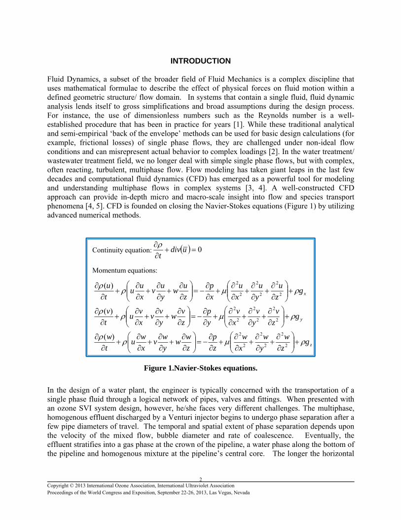
Fluid Dynamics, a subset of the broader field of Fluid Mechanics is a complex discipline that uses mathematical formulae to describe the effect of physical forces on fluid motion within a defined geometric structure/ flow domain. In systems that contain a single fluid, fluid dynamic analysis lends itself to gross simplifications and broad assumptions during the design process. For instance, the use of dimensionless numbers such as the Reynolds number is a well-established procedure that has been in practice for years [1]. While these traditional analytical and semi-empirical ‘back of the envelope’ methods can be used for basic design calculations (for example, frictional losses) of single phase flows, they are challenged under non-ideal flow conditions and can misrepresent actual behavior to complex loadings [2]. In the water treatment/ wastewater treatment field, we no longer deal with simple single phase flows, but with complex, often reacting, turbulent, multiphase flow. Flow modeling has taken giant leaps in the last few decades and computational fluid dynamics (CFD) has emerged as a powerful tool for modeling and understanding multiphase flows in complex systems [3, 4]. A well-constructed CFD approach can provide in-depth micro and macro-scale insight into flow and species transport phenomena [4, 5]. CFD is founded on closing the Navier-Stokes equations (Figure 1) by utilizing advanced numerical methods.
Figure 1.Navier-Stokes equations.
In the design of a water plant, the engineer is typically concerned with the transportation of a single phase fluid through a logical network of pipes, valves and fittings. When presented with an ozone SVI system design, however, he/she faces very different challenges. The multiphase, homogenous effluent discharged by a Venturi injector begins to undergo phase separation after a few pipe diameters of travel. The temporal and spatial extent of phase separation depends upon the velocity of the mixed flow, bubble diameter and rate of coalescence. Eventually, the effluent stratifies into a gas phase at the crown of the pipeline, a water phase along the bottom of the pipeline and homogenous mixture at the pipeline’s central core. The longer the horizontal
0
udivt
xgz
u
y
u
x
u
x
p
z
uw
y
uv
x
uu
t
u
2
2
2
2
2
2)(
ygz
v
y
v
x
v
y
p
z
vw
y
vv
x
vu
t
v
2
2
2
2
2
2)(
zgz
w
y
w
x
w
z
p
z
ww
y
wv
x
wu
t
w
2
2
2
2
2
2)(
Continuity equation:
Momentum equations:
3 Copyright © 2013 International Ozone Association, International Ultraviolet Association Proceedings of the World Congress and Exposition, September 22-26, 2013, Las Vegas, Nevada
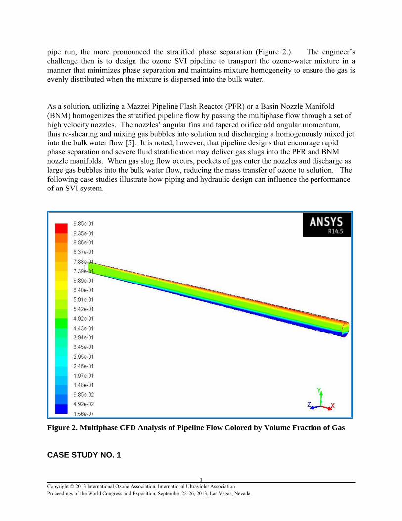
pipe run, the more pronounced the stratified phase separation (Figure 2.). The engineer’s challenge then is to design the ozone SVI pipeline to transport the ozone-water mixture in a manner that minimizes phase separation and maintains mixture homogeneity to ensure the gas is evenly distributed when the mixture is dispersed into the bulk water. As a solution, utilizing a Mazzei Pipeline Flash Reactor (PFR) or a Basin Nozzle Manifold (BNM) homogenizes the stratified pipeline flow by passing the multiphase flow through a set of high velocity nozzles. The nozzles’ angular fins and tapered orifice add angular momentum, thus re-shearing and mixing gas bubbles into solution and discharging a homogenously mixed jet into the bulk water flow [5]. It is noted, however, that pipeline designs that encourage rapid phase separation and severe fluid stratification may deliver gas slugs into the PFR and BNM nozzle manifolds. When gas slug flow occurs, pockets of gas enter the nozzles and discharge as large gas bubbles into the bulk water flow, reducing the mass transfer of ozone to solution. The following case studies illustrate how piping and hydraulic design can influence the performance of an SVI system.
Figure 2. Multiphase CFD Analysis of Pipeline Flow Colored by Volume Fraction of Gas CASE STUDY NO. 1
4 Copyright © 2013 International Ozone Association, International Ultraviolet Association Proceedings of the World Congress and Exposition, September 22-26, 2013, Las Vegas, Nevada
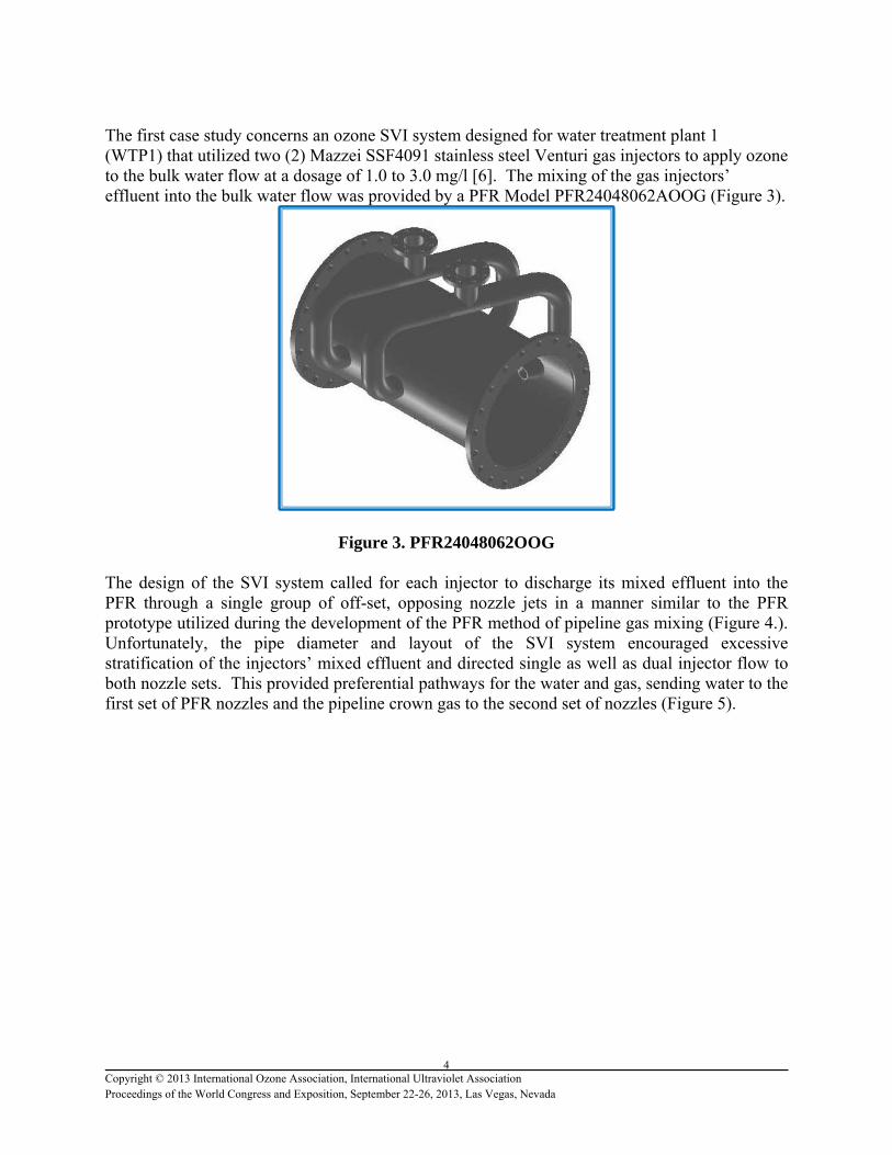
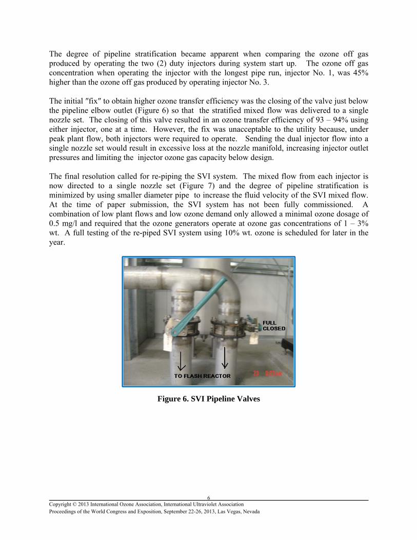
The first case study concerns an ozone SVI system designed for water treatment plant 1 (WTP1) that utilized two (2) Mazzei SSF4091 stainless steel Venturi gas injectors to apply ozone to the bulk water flow at a dosage of 1.0 to 3.0 mg/l [6]. The mixing of the gas injectors’ effluent into the bulk water flow was provided by a PFR Model PFR24048062AOOG (Figure 3).
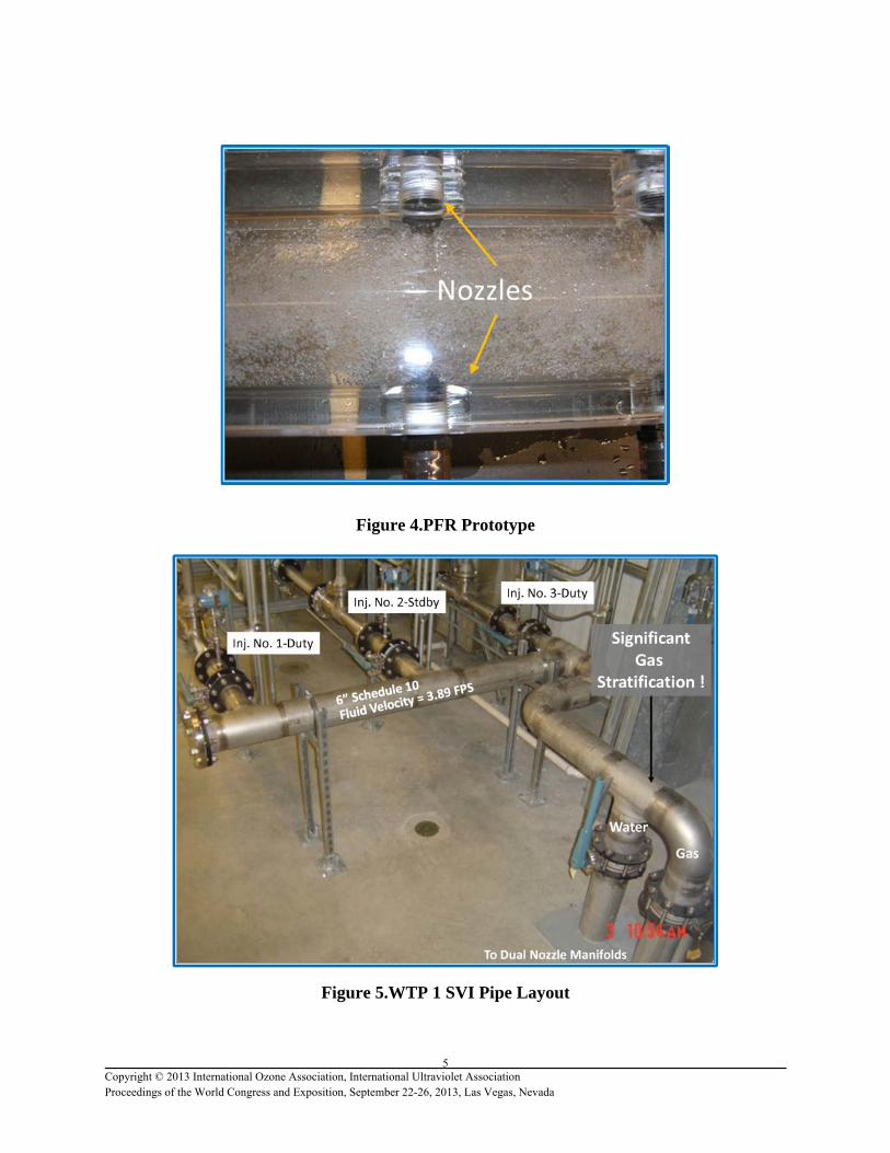
Figure 3. PFR24048062OOG The design of the SVI system called for each injector to discharge its mixed effluent into the PFR through a single group of off-set, opposing nozzle jets in a manner similar to the PFR prototype utilized during the development of the PFR method of pipeline gas mixing (Figure 4.). Unfortunately, the pipe diameter and layout of the SVI system encouraged excessive stratification of the injectors’ mixed effluent and directed single as well as dual injector flow to both nozzle sets. This provided preferential pathways for the water and gas, sending water to the first set of PFR nozzles and the pipeline crown gas to the second set of nozzles (Figure 5).
5 Copyright © 2013 International Ozone Association, International Ultraviolet Association Proceedings of the World Congress and Exposition, September 22-26, 2013, Las Vegas, Nevada
Figure 4.PFR Prototype
Figure 5.WTP 1 SVI Pipe Layout
6 Copyright © 2013 International Ozone Association, International Ultraviolet Association Proceedings of the World Congress and Exposition, September 22-26, 2013, Las Vegas, Nevada
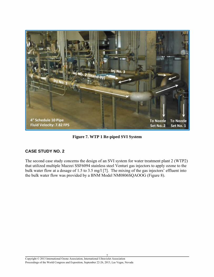
The degree of pipeline stratification became apparent when comparing the ozone off gas produced by operating the two (2) duty injectors during system start up. The ozone off gas concentration when operating the injector with the longest pipe run, injector No. 1, was 45% higher than the ozone off gas produced by operating injector No. 3. The initial ″fix″ to obtain higher ozone transfer efficiency was the closing of the valve just below the pipeline elbow outlet (Figure 6) so that the stratified mixed flow was delivered to a single nozzle set. The closing of this valve resulted in an ozone transfer efficiency of 93 – 94% using either injector, one at a time. However, the fix was unacceptable to the utility because, under peak plant flow, both injectors were required to operate. Sending the dual injector flow into a single nozzle set would result in excessive loss at the nozzle manifold, increasing injector outlet pressures and limiting the injector ozone gas capacity below design. The final resolution called for re-piping the SVI system. The mixed flow from each injector is now directed to a single nozzle set (Figure 7) and the degree of pipeline stratification is minimized by using smaller diameter pipe to increase the fluid velocity of the SVI mixed flow. At the time of paper submission, the SVI system has not been fully commissioned. A combination of low plant flows and low ozone demand only allowed a minimal ozone dosage of 0.5 mg/l and required that the ozone generators operate at ozone gas concentrations of 1 – 3% wt. A full testing of the re-piped SVI system using 10% wt. ozone is scheduled for later in the year.
Figure 6. SVI Pipeline Valves
7 Copyright © 2013 International Ozone Association, International Ultraviolet Association Proceedings of the World Congress and Exposition, September 22-26, 2013, Las Vegas, Nevada
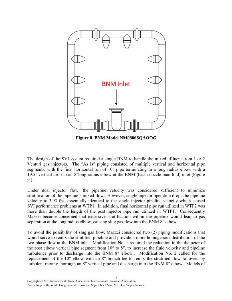
Figure 7. WTP 1 Re-piped SVI System CASE STUDY NO. 2 The second case study concerns the design of an SVI system for water treatment plant 2 (WTP2) that utilized multiple Mazzei SSF6094 stainless steel Venturi gas injectors to apply ozone to the bulk water flow at a dosage of 1.5 to 3.5 mg/l [7]. The mixing of the gas injectors’ effluent into the bulk water flow was provided by a BNM Model NM0806SQAOOG (Figure 8).
8 Copyright © 2013 International Ozone Association, International Ultraviolet Association Proceedings of the World Congress and Exposition, September 22-26, 2013, Las Vegas, Nevada
Figure 8. BNM Model NM0806SQAOOG The design of the SVI system required a single BNM to handle the mixed effluent from 1 or 2 Venturi gas injectors. The ″As is″ piping consisted of multiple vertical and horizontal pipe segments, with the final horizontal run of 10″ pipe terminating in a long radius elbow with a 19.5’ vertical drop to an 8″long radius elbow at the BNM (basin nozzle manifold) inlet (Figure 9.). Under dual injector flow, the pipeline velocity was considered sufficient to minimize stratification of the pipeline’s mixed flow. However, single injector operation drops the pipeline velocity to 3.93 fps, essentially identical to the single injector pipeline velocity which caused SVI performance problems at WTP1. In addition, final horizontal pipe run utilized in WTP2 was more than double the length of the post injector pipe run utilized in WTP1. Consequently Mazzei became concerned that excessive stratification within the pipeline would lead to gas separation at the long radius elbow, causing slug gas flow into the BNM 8″ elbow. To avoid the possibility of slug gas flow, Mazzei considered two (2) piping modifications that would serve to remix the stratified pipeline and provide a more homogenous distribution of the two phase flow at the BNM inlet. Modification No. 1 required the reduction in the diameter of the post elbow vertical pipe segment from 10″ to 8″, to increase the fluid velocity and pipeline turbulence prior to discharge into the BNM 8″ elbow.. Modification No. 2 called for the replacement of the 10″ elbow with an 8″ branch tee to remix the stratified flow followed by turbulent mixing thorough an 8″ vertical pipe and discharge into the BNM 8″ elbow. Models of
9 Copyright © 2013 International Ozone Association, International Ultraviolet Association Proceedings of the World Congress and Exposition, September 22-26, 2013, Las Vegas, Nevada
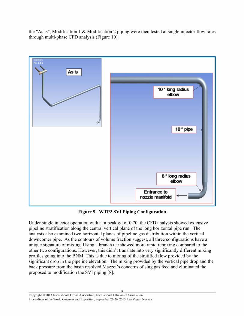
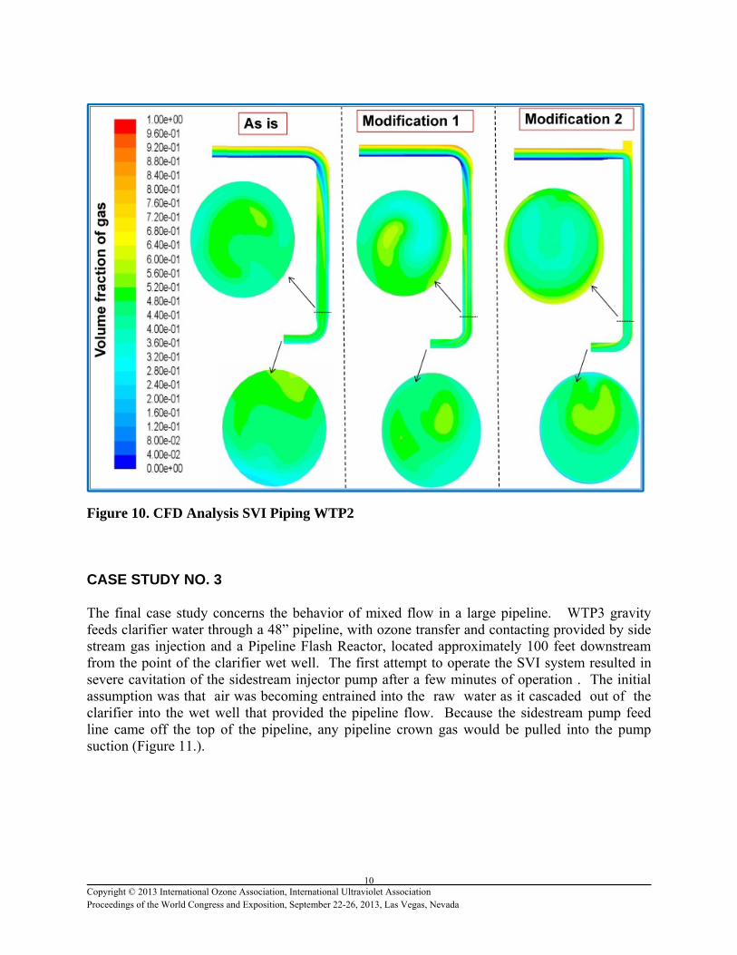
the ″As is″, Modification 1 & Modification 2 piping were then tested at single injector flow rates through multi-phase CFD analysis (Figure 10).
Figure 9. WTP2 SVI Piping Configuration Under single injector operation with at a peak g/l of 0.70, the CFD analysis showed extensive pipeline stratification along the central vertical plane of the long horizontal pipe run. The analysis also examined two horizontal planes of pipeline gas distribution within the vertical downcomer pipe. As the contours of volume fraction suggest, all three configurations have a unique signature of mixing. Using a branch tee showed more rapid remixing compared to the other two configurations. However, this didn’t translate into very significantly different mixing profiles going into the BNM. This is due to mixing of the stratified flow provided by the significant drop in the pipeline elevation. The mixing provided by the vertical pipe drop and the back pressure from the basin resolved Mazzei’s concerns of slug gas feed and eliminated the proposed to modification the SVI piping [8].
10 Copyright © 2013 International Ozone Association, International Ultraviolet Association Proceedings of the World Congress and Exposition, September 22-26, 2013, Las Vegas, Nevada
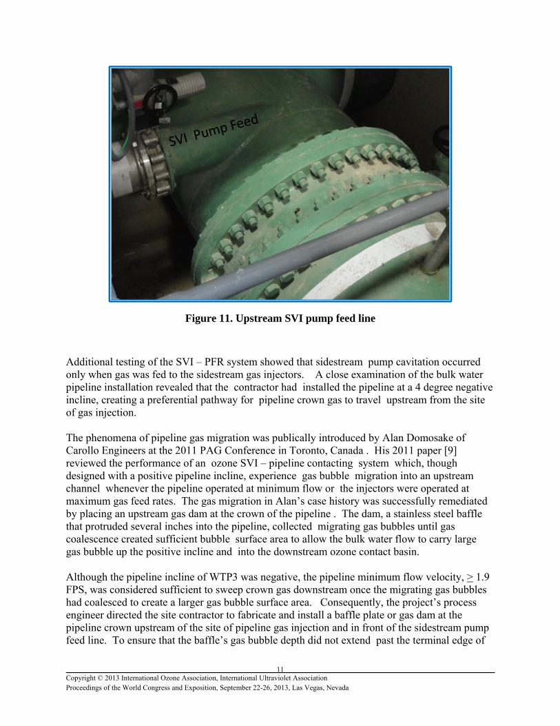
Figure 10. CFD Analysis SVI Piping WTP2 CASE STUDY NO. 3 The final case study concerns the behavior of mixed flow in a large pipeline. WTP3 gravity feeds clarifier water through a 48” pipeline, with ozone transfer and contacting provided by side stream gas injection and a Pipeline Flash Reactor, located approximately 100 feet downstream from the point of the clarifier wet well. The first attempt to operate the SVI system resulted in severe cavitation of the sidestream injector pump after a few minutes of operation . The initial assumption was that air was becoming entrained into the raw water as it cascaded out of the clarifier into the wet well that provided the pipeline flow. Because the sidestream pump feed line came off the top of the pipeline, any pipeline crown gas would be pulled into the pump suction (Figure 11.).
11 Copyright © 2013 International Ozone Association, International Ultraviolet Association Proceedings of the World Congress and Exposition, September 22-26, 2013, Las Vegas, Nevada
Figure 11. Upstream SVI pump feed line
Additional testing of the SVI – PFR system showed that sidestream pump cavitation occurred only when gas was fed to the sidestream gas injectors. A close examination of the bulk water pipeline installation revealed that the contractor had installed the pipeline at a 4 degree negative incline, creating a preferential pathway for pipeline crown gas to travel upstream from the site of gas injection. The phenomena of pipeline gas migration was publically introduced by Alan Domosake of Carollo Engineers at the 2011 PAG Conference in Toronto, Canada . His 2011 paper [9] reviewed the performance of an ozone SVI – pipeline contacting system which, though designed with a positive pipeline incline, experience gas bubble migration into an upstream channel whenever the pipeline operated at minimum flow or the injectors were operated at maximum gas feed rates. The gas migration in Alan’s case history was successfully remediated by placing an upstream gas dam at the crown of the pipeline . The dam, a stainless steel baffle that protruded several inches into the pipeline, collected migrating gas bubbles until gas coalescence created sufficient bubble surface area to allow the bulk water flow to carry large gas bubble up the positive incline and into the downstream ozone contact basin. Although the pipeline incline of WTP3 was negative, the pipeline minimum flow velocity, > 1.9 FPS, was considered sufficient to sweep crown gas downstream once the migrating gas bubbles had coalesced to create a larger gas bubble surface area. Consequently, the project’s process engineer directed the site contractor to fabricate and install a baffle plate or gas dam at the pipeline crown upstream of the site of pipeline gas injection and in front of the sidestream pump feed line. To ensure that the baffle’s gas bubble depth did not extend past the terminal edge of
12 Copyright © 2013 International Ozone Association, International Ultraviolet Association Proceedings of the World Congress and Exposition, September 22-26, 2013, Las Vegas, Nevada
the baffle plate, a vent pipe with a manually actuated valve was placed immediately upstream of the gas dam.
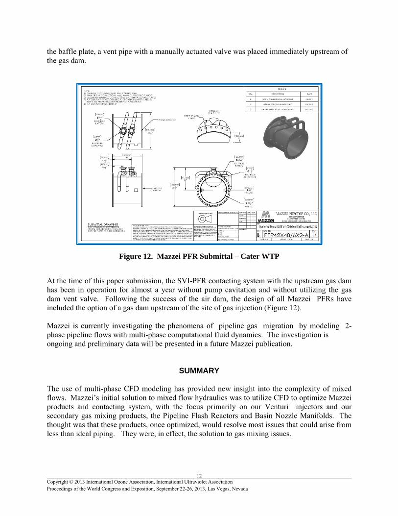
Figure 12. Mazzei PFR Submittal – Cater WTP
At the time of this paper submission, the SVI-PFR contacting system with the upstream gas dam has been in operation for almost a year without pump cavitation and without utilizing the gas dam vent valve. Following the success of the air dam, the design of all Mazzei PFRs have included the option of a gas dam upstream of the site of gas injection (Figure 12). Mazzei is currently investigating the phenomena of pipeline gas migration by modeling 2- phase pipeline flows with multi-phase computational fluid dynamics. The investigation is ongoing and preliminary data will be presented in a future Mazzei publication.
SUMMARY The use of multi-phase CFD modeling has provided new insight into the complexity of mixed flows. Mazzei’s initial solution to mixed flow hydraulics was to utilize CFD to optimize Mazzei products and contacting system, with the focus primarily on our Venturi injectors and our secondary gas mixing products, the Pipeline Flash Reactors and Basin Nozzle Manifolds. The thought was that these products, once optimized, would resolve most issues that could arise from less than ideal piping. They were, in effect, the solution to gas mixing issues.
13 Copyright © 2013 International Ozone Association, International Ultraviolet Association Proceedings of the World Congress and Exposition, September 22-26, 2013, Las Vegas, Nevada
However, recent project experience combined with an expanded use of multi-phase CFD for modeling mixed pipeline flows, has led Mazzei to gain a greater appreciation of how mixed flow hydraulics, when handled incorrectly in the design of the interconnection piping between our gas injectors and our secondary gas devices, can significantly reduce the performance of our gas injection systems. Consequently, Mazzei has developed new, more detailed installation guidelines and now plays a bigger role during the design phase of an ozone water or wastewater plant that will include a Mazzei ozone injection system. Details on the Mazzei guidelines for installing SVI systems can be found at Mazzei.net/Knowledge Center/Technical Bulletins/Tech Bulletin 11.
References
1. Tchobanoglous, G., F.L. Burton, and H. D. Stensel (Eds.) (2003), Wastewater Engineering:Treatment, Disposal, and Reuse, 4th Ed., Metcalf and Eddy Inc., McGraw Hill, Inc., New York.
2. Pathapati, S. and Sansalone, J. (2011), “Can a stepwise steady flow CFD model reproduce unsteady PM separation for common unit operations?” Environmental Science and Technology, 45 (13).
3. Ranade, V. V (2002), Computational flow modeling for chemical reactor engineering, 1st Ed., Academic Press, London, UK.
4. Pathapati, S., and Sansalone, J.J. (2009) CFD Modeling of a Stormwater Hydrodynamic Separator. J. Environmental Engineering -ASCE, 135 (4), 191-202.
5. Baawain, M.S., M. Gamal El-Din, D.W. Smith, and A. Mazzei “Hydrodynamic Characterization of an in-Line Opposing-Jets Ozone Contactor”, In Proc. of World Congress on Ozone and Ultraviolet Technologies (IOA/IUVA 2007), Los Angeles, CA USA, 10 p. (August 27-29, 2007).
6. Mazzei Project No. 1190 specifications, design notes and calculations.
7. Mazzei Project No. 1122 specifications, design notes and calculations.
8. Comparative Study of Stratification and Pressure Loss, Wylie WTP, Mazzei Injector Company LLC, January 31, 2013.
9. Alan Domonsake et al, “Ozone Sidestream Injection: Solving Start-Up Problems Using Underwater Video and Engineering Creativity” In Proc. of IOA PAG 2011, Toronto, Canada


![[PPT]Fundamentals of Process Plant Piping Designmetroc.ca/schedule/piping-design-presentation.ppsx · Web viewFundamentals ofPROCESS PLANT PIPING DESIGN … JOB … JOB … JOB …](https://img.pdfslide.net/doc/110x75/5b4648527f8b9afb078b75f9/pptfundamentals-of-process-plant-piping-web-viewfundamentals-ofprocess-plant.jpg)