Embed Size (px)
Citation preview
Effects of Impactor Geometry on the Low-VelocityImpact Behaviour of Fibre-Reinforced Composites:An Experimental and Theoretical Investigation
Haibao Liu1 & Jun Liu1 & Yuzhe Ding1 & Jin Zhou2 & Xiangshao Kong3 &
Bamber R.K. Blackman1 & Anthony J. Kinloch1 & Brian G. Falzon4 & John P. Dear1
# The Author(s) 2020
AbstractCarbon-fibre/epoxy-matrix composites used in aerospace and vehicle applications are oftensusceptible to critical loading conditions and one example is impact loading. The presentpaper describes a detailed experimental and numerical investigation on the relatively low-velocity (i.e. <10 m/s) impact behaviour of such composite laminates. In particular, theeffects of the geometry of the impactor have been studied and two types of impactor wereinvestigated: (a) a steel impactor with a hemispherical head and (b) a flat-ended steelimpactor. They were employed to strike the composite specimens with an impact energylevel of 15 J. After the impact experiments, all the composite laminates were inspected usingultrasonic C-scan tests to assess the damage that was induced by the two different types ofimpactor. A three-dimensional finite-element (FE) model, incorporating a newly developedelastic-plastic damage model which was implemented as a VUMAT subroutine, wasemployed to simulate the impact event and to investigate the effects of the geometry ofthe impactor. The numerical predictions, including those for the loading response and thedamage maps, gave good agreement with the experimental results.
Keywords Composite laminates . Finite-element analysis . Low-velocity impact .Modelling .
Numerical simulation
1 Introduction
Due to their high strength-to-weight ratio, carbon-fibre reinforced composite laminates, using athermosetting epoxy polymer matrix, have been widely used in the manufacture of structuralcomponents for commercial aircraft and vehicles [1–3]. However, their wider application in primary
https://doi.org/10.1007/s10443-020-09812-8
* Anthony J. [email protected]
* John P. [email protected]
Extended author information available on the last page of the article
Received: 3 April 2020 /Accepted: 11 May 2020 /Published online: 17 June 2020
Applied Composite Materials (2020) 27:533–553
load-carrying structures has been hindered by their reduced impact performance compared to that ofmore traditional metallic materials [4–6]. In particular, impact loading can lead to damage whichmay not be necessarily visible but which may, nonetheless, lead to a significant strength reduction[7–10]. To enhance confidence when using composite materials in the latest generation of aircraftand vehicles a better understanding of the impact behaviour of composite materials is needed.Driven by this requirement, considerable efforts have been made by both academia and industry tostudy and improve the impact performance of such composite laminates e.g. [11–24].
Experiments are an essential way to understand the impact behaviour of composite laminatesbut only a relatively small number of comparative studies have been reported on the effects of theshape of the impactor head. Mitrevski et al. [17] have reported the effect of impactor shape on theimpact behaviour of woven carbon-fibre/epoxy-matrix composites. Their studies involved thelow-velocity impact of the composites using 12 mm diameter hemispherical, ogival and conicalhead-shaped impactors at impact energies of 4 J and 6 J. They found that the energy absorbed bythe specimen was the highest for the conical impactor which also produced the largest penetrationdepth. However, the peak load was greatest for the hemispherical impactor which also producedthe shortest contact duration. In a subsequent paper [18] it was reported that different impactorhead-shapes produced different levels of the various types of damage that were observed, such asfibre breakage, matrix cracking and delamination, which affected the residual properties of thecomposite. It was found that the relatively blunt hemispherical impactor produced the largestdamage area and the type of damage was dominated by delamination. Robinson and Davies [19]have reported results from drop-weight tests using a hemispherically-shaped impactor at impactvelocities of up 6.0 m/s striking woven glass- and carbon-fibre composites based on amatrix of anacrylic polymer. They found that the impact damage caused was mainly a function of the impactenergy, and not the velocity or mass, separately, of the impactor. Further, the measured peak loadwas also shown to correlate with the impact energy independent of the impactor mass used,indicating that the low-velocity impact of these specimens was a quasi-static process. Their testresults also indicated that the peak load versus damage size relationship was independent of thediameter of the impactor.More recently, Sevkat et al. [20] have undertaken drop-weight tests at animpact velocity of 4.1 m/s on woven glass-fibre/carbon-fibre hybrid epoxy composites. Theyreported that the contact area between the impactor and the composite test specimen was a criticalfactor in the response of the composites. Impactors with relatively large contact surfaces produceda higher initial load peak, a higher maximum load, a shorter contact duration for the time-scale ofthe impact event and more extensive delaminations between the hybrid layers.
Another effective approach to investigate the impact response of composite laminates is bydeveloping analytical and numerical models. Analytical models are more suited to understand-ing the physics of the impact effects and have better computational efficiency, since they tendto be relatively tractable using simple geometries and boundary conditions. Numerical modelsare more suitable when trying to represent reality more closely, which should also lead to abetter understanding of the impact behaviour of composites. For example, to simulate thebehaviour of composite laminates under a large mass, low-velocity impact, Olsson proposed asimplified analytical model to predict the initiation and propagation of impact damage incomposites [21, 22]. Analytical results were compared with experimental results obtained fromcomposites with different lay-ups, geometries and boundary conditions. It was found that thecritical load for delamination growth was insensitive to the specimen geometry and boundaryconditions. A relatively high computational efficiency, for the level of accuracy achieved, wasdemonstrated by the analytical model when it was employed to predict the impact behaviour ofcomposite laminates which did not experience extensive fibre breakage. On the other hand,
Applied Composite Materials (2020) 27:533–553534
Bouvet et al. [23, 24] have used a numerical model to capture the different types of damagewithin composite laminates subjected to a relatively low-velocity/low-energy impact. In theirnumerical model, three types of damage, namely fibre failure, matrix cracking and delamina-tion, were considered. Delamination was conventionally modelled using interface elementsbased on a fracture mechanics approach. Fibre failure was simulated using degradation of thevolumetric elements. For simulating intralaminar matrix cracking, a series of longitudinalstrips, with one volume element through the ply thickness, were modelled and connected usingzero-thickness interface elements.
In the present work, a detailed study of the impact behaviour of composite laminates wasconducted using both experimental and numerical methods. For the experimental studies, panels ofcarbon-fibre/epoxy-matrix composite laminates, with a lay-up of [+453/03/−453/03]s, weremanufactured. The composite specimens, produced from the composite panels, were then employedto perform the drop-weight impact experiments. The specimen dimensions and experimental set-updescribed in ASTM D-7136 standard [25] were adopted. Hemispherical steel impactors or flat-ended steel impactors were used to strike the composite specimens with 15 J of energy. Subse-quently, all the tested specimens were examined using ultrasonic C-scanning to evaluate the extentof damage due the different impactors. For the numerical studies, a detailed finite-element (FE)model was developed within the commercial software code ‘Abaqus’ to simulate the drop-weightimpact tests. This approach follows on from previous research performed at Queen’s UniversityBelfast, in the Advanced Composites Research Group, and a novel aspect of the current research isto enhance the previous numerical analyses with an elastic-plastic model. The validated FE model,incorporating the elastic-plastic material response, was employed (a) to determine the damagedistribution and deformation in the composite specimen and (b) to gain further insights into theeffects of the shape of the impacting projectile on the impact behaviour of composite laminates.
2 Impactors and Specimens
2.1 Impactors
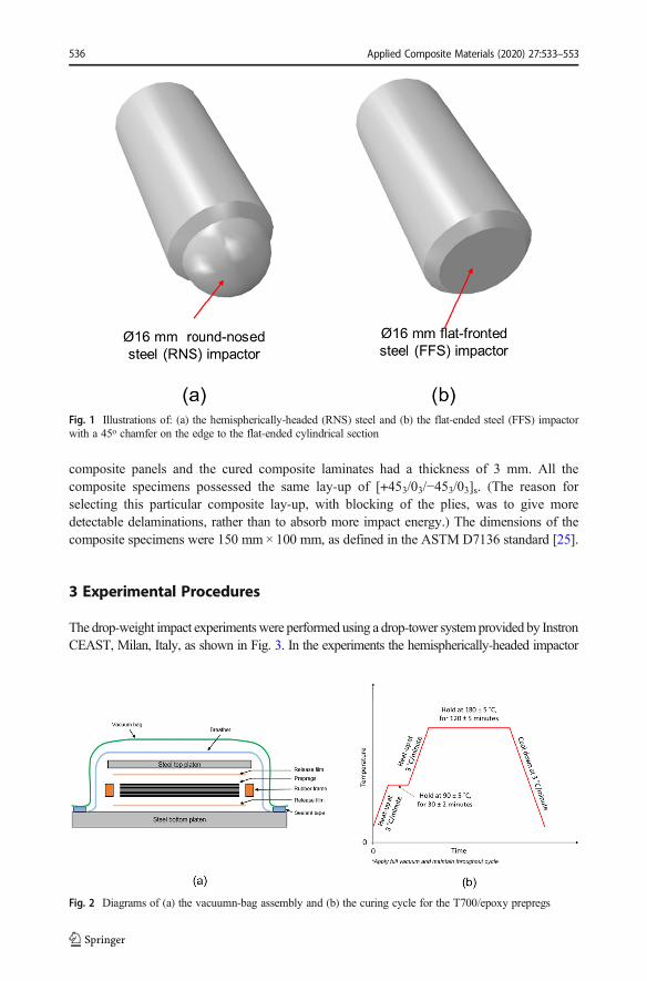
Two types of impactors with different shaped heads were used: a hemispherical steel (i.e. around-nosed steel (RNS)) impactor and a flat-ended (i.e. a flat-faced steel (FFS)) steelimpactor. The hemispherically-headed steel impactor and the flat-ended steel impactor weremanufactured from stainless steel and are illustrated in Fig. 1. They had masses of 5.20 and5.25 kg, respectively, and the impact velocities used were 2.40 m/s and 2.39 m/s respectively.The impact energy was 15 J in both cases. The impactor heads had a diameter of 16 mm, withthe head of the flat-ended impactor having a chamfer of about 45o around its periphery, asshown in Fig. 1. The diameter of the main body of the impactor was 20 mm and the load cell,with a data sampling rate of 500 kHz, was located in the forward section of the impactor.
2.2 Composite Specimens
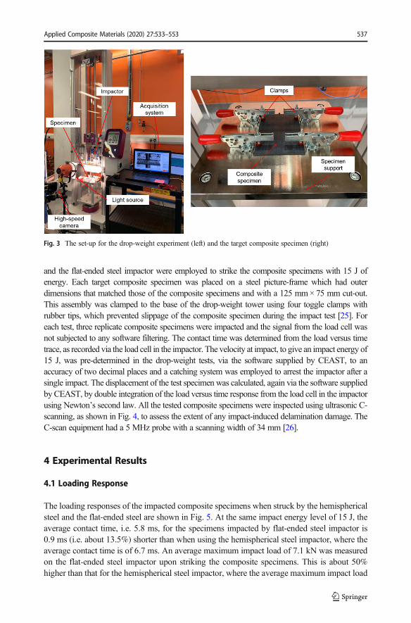
Composite laminates were manufactured from unidirectional (T700) carbon-fibre reinforcedepoxy-matrix pre-pregs. The stacked prepregs, provided by Beian Ltd., China, were cured inan autoclave. A schematic of the vacuum-bagging procedure for the autoclave and the curingcycle for the T700/epoxy pre-pregs (0.125 mm in thickness) are presented in Fig. 2. Compositetest specimens for the drop-weight impact experiments were produced from the manufactured
Applied Composite Materials (2020) 27:533–553 535
composite panels and the cured composite laminates had a thickness of 3 mm. All thecomposite specimens possessed the same lay-up of [+453/03/−453/03]s. (The reason forselecting this particular composite lay-up, with blocking of the plies, was to give moredetectable delaminations, rather than to absorb more impact energy.) The dimensions of thecomposite specimens were 150 mm× 100 mm, as defined in the ASTM D7136 standard [25].
3 Experimental Procedures
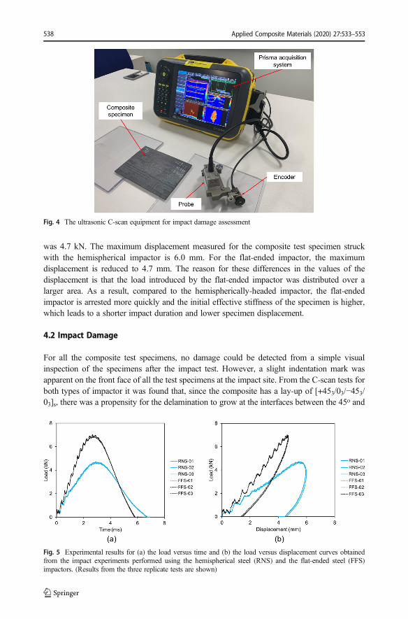
The drop-weight impact experimentswere performed using a drop-tower systemprovided by InstronCEAST, Milan, Italy, as shown in Fig. 3. In the experiments the hemispherically-headed impactor
Fig. 1 Illustrations of: (a) the hemispherically-headed (RNS) steel and (b) the flat-ended steel (FFS) impactorwith a 45o chamfer on the edge to the flat-ended cylindrical section
Fig. 2 Diagrams of (a) the vacuumn-bag assembly and (b) the curing cycle for the T700/epoxy prepregs
Applied Composite Materials (2020) 27:533–553536
and the flat-ended steel impactor were employed to strike the composite specimens with 15 J ofenergy. Each target composite specimen was placed on a steel picture-frame which had outerdimensions that matched those of the composite specimens and with a 125 mm×75 mm cut-out.This assembly was clamped to the base of the drop-weight tower using four toggle clamps withrubber tips, which prevented slippage of the composite specimen during the impact test [25]. Foreach test, three replicate composite specimens were impacted and the signal from the load cell wasnot subjected to any software filtering. The contact time was determined from the load versus timetrace, as recorded via the load cell in the impactor. The velocity at impact, to give an impact energy of15 J, was pre-determined in the drop-weight tests, via the software supplied by CEAST, to anaccuracy of two decimal places and a catching system was employed to arrest the impactor after asingle impact. The displacement of the test specimen was calculated, again via the software suppliedby CEAST, by double integration of the load versus time response from the load cell in the impactorusing Newton’s second law. All the tested composite specimens were inspected using ultrasonic C-scanning, as shown in Fig. 4, to assess the extent of any impact-induced delamination damage. TheC-scan equipment had a 5 MHz probe with a scanning width of 34 mm [26].
4 Experimental Results
4.1 Loading Response
The loading responses of the impacted composite specimens when struck by the hemisphericalsteel and the flat-ended steel are shown in Fig. 5. At the same impact energy level of 15 J, theaverage contact time, i.e. 5.8 ms, for the specimens impacted by flat-ended steel impactor is0.9 ms (i.e. about 13.5%) shorter than when using the hemispherical steel impactor, where theaverage contact time is of 6.7 ms. An average maximum impact load of 7.1 kN was measuredon the flat-ended steel impactor upon striking the composite specimens. This is about 50%higher than that for the hemispherical steel impactor, where the average maximum impact load
Fig. 3 The set-up for the drop-weight experiment (left) and the target composite specimen (right)
Applied Composite Materials (2020) 27:533–553 537
was 4.7 kN. The maximum displacement measured for the composite test specimen struckwith the hemispherical impactor is 6.0 mm. For the flat-ended impactor, the maximumdisplacement is reduced to 4.7 mm. The reason for these differences in the values of thedisplacement is that the load introduced by the flat-ended impactor was distributed over alarger area. As a result, compared to the hemispherically-headed impactor, the flat-endedimpactor is arrested more quickly and the initial effective stiffness of the specimen is higher,which leads to a shorter impact duration and lower specimen displacement.
4.2 Impact Damage
For all the composite test specimens, no damage could be detected from a simple visualinspection of the specimens after the impact test. However, a slight indentation mark wasapparent on the front face of all the test specimens at the impact site. From the C-scan tests forboth types of impactor it was found that, since the composite has a lay-up of [+453/03/−453/03]s, there was a propensity for the delamination to grow at the interfaces between the 45o and
Fig. 4 The ultrasonic C-scan equipment for impact damage assessment
Fig. 5 Experimental results for (a) the load versus time and (b) the load versus displacement curves obtainedfrom the impact experiments performed using the hemispherical steel (RNS) and the flat-ended steel (FFS)impactors. (Results from the three replicate tests are shown)
Applied Composite Materials (2020) 27:533–553538
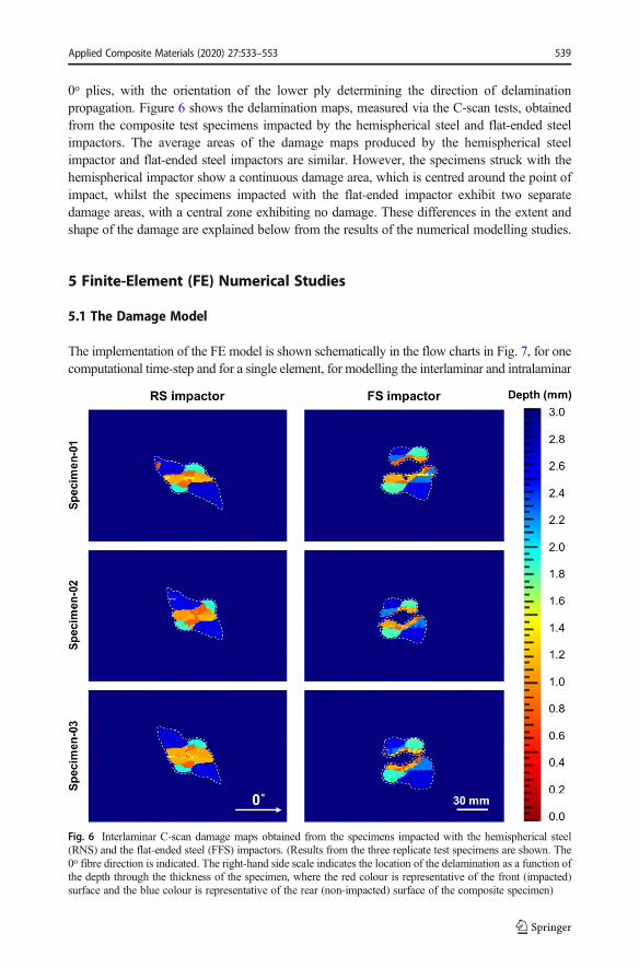
0o plies, with the orientation of the lower ply determining the direction of delaminationpropagation. Figure 6 shows the delamination maps, measured via the C-scan tests, obtainedfrom the composite test specimens impacted by the hemispherical steel and flat-ended steelimpactors. The average areas of the damage maps produced by the hemispherical steelimpactor and flat-ended steel impactors are similar. However, the specimens struck with thehemispherical impactor show a continuous damage area, which is centred around the point ofimpact, whilst the specimens impacted with the flat-ended impactor exhibit two separatedamage areas, with a central zone exhibiting no damage. These differences in the extent andshape of the damage are explained below from the results of the numerical modelling studies.
5 Finite-Element (FE) Numerical Studies
5.1 The Damage Model
The implementation of the FE model is shown schematically in the flow charts in Fig. 7, for onecomputational time-step and for a single element, for modelling the interlaminar and intralaminar
Fig. 6 Interlaminar C-scan damage maps obtained from the specimens impacted with the hemispherical steel(RNS) and the flat-ended steel (FFS) impactors. (Results from the three replicate test specimens are shown. The0o fibre direction is indicated. The right-hand side scale indicates the location of the delamination as a function ofthe depth through the thickness of the specimen, where the red colour is representative of the front (impacted)surface and the blue colour is representative of the rear (non-impacted) surface of the composite specimen)
Applied Composite Materials (2020) 27:533–553 539
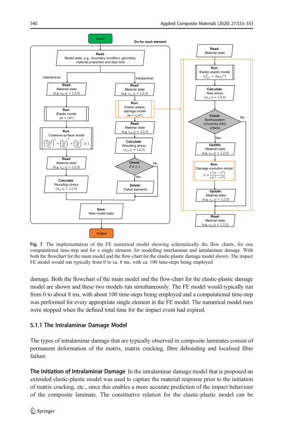
damage. Both the flowchart of the main model and the flow-chart for the elastic-plastic damagemodel are shown and these two models run simultaneously. The FE model would typically runfrom 0 to about 8 ms, with about 100 time-steps being employed and a computational time-stepwas performed for every appropriate single element in the FE model. The numerical model runswere stopped when the defined total time for the impact event had expired.
5.1.1 The Intralaminar Damage Model
The types of intralaminar damage that are typically observed in composite laminates consist ofpermanent deformation of the matrix, matrix cracking, fibre debonding and localised fibrefailure.
The Initiation of Intralaminar Damage In the intralaminar damage model that is proposed anextended elastic-plastic model was used to capture the material response prior to the initiationof matrix cracking, etc., since this enables a more accurate prediction of the impact behaviourof the composite laminate. The constitutive relation for the elastic-plastic model can be
Fig. 7 The implementation of the FE numerical model showing schematically the flow charts, for onecomputational time-step and for a single element, for modelling interlaminar and intralaminar damage. Withboth the flowchart for the main model and the flow-chart for the elastic-plastic damage model shown. The impactFE model would run typically from 0 to ca. 8 ms, with ca. 100 time-steps being employed
Applied Composite Materials (2020) 27:533–553540
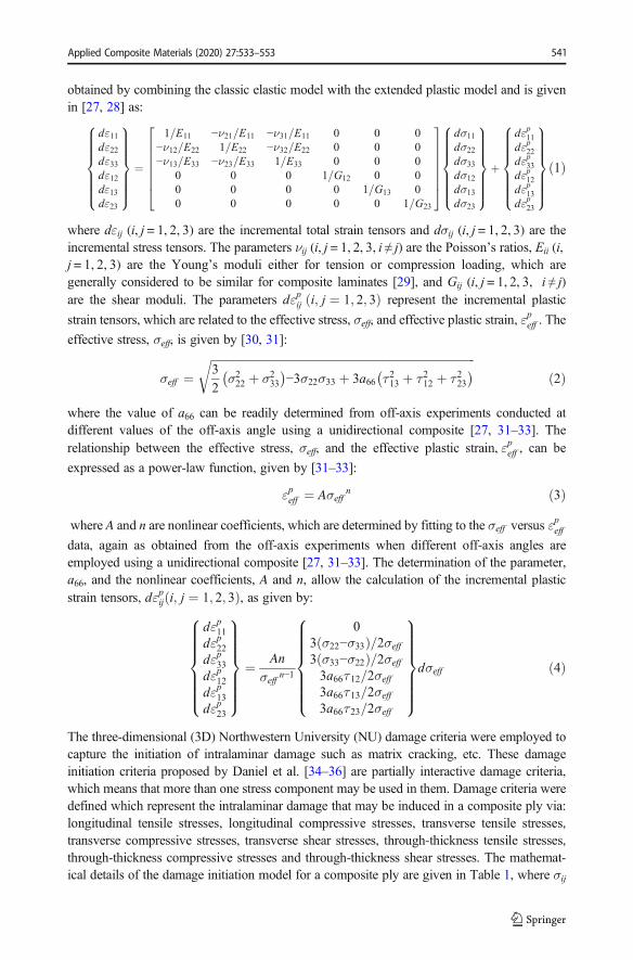
obtained by combining the classic elastic model with the extended plastic model and is givenin [27, 28] as:
dε11dε22dε33dε12dε13dε23
8>>>>>><>>>>>>:
9>>>>>>=>>>>>>;
¼
1=E11 −ν21=E11 −ν31=E11 0 0 0−ν12=E22 1=E22 −ν32=E22 0 0 0−ν13=E33 −ν23=E33 1=E33 0 0 0
0 0 0 1=G12 0 00 0 0 0 1=G13 00 0 0 0 0 1=G23
26666664
37777775
dσ11dσ22dσ33dσ12dσ13dσ23
8>>>>>><>>>>>>:
9>>>>>>=>>>>>>;
þ
dεp11dεp22dεp33dεp12dεp13dεp23
8>>>>>><>>>>>>:
9>>>>>>=>>>>>>;ð1Þ
where dεij (i, j = 1, 2, 3) are the incremental total strain tensors and dσij (i, j = 1, 2, 3) are theincremental stress tensors. The parameters νij (i, j = 1, 2, 3, i ≠ j) are the Poisson’s ratios, Eii (i,j = 1, 2, 3) are the Young’s moduli either for tension or compression loading, which aregenerally considered to be similar for composite laminates [29], and Gij (i, j = 1, 2, 3, i ≠ j)are the shear moduli. The parameters dεpij i; j ¼ 1; 2; 3ð Þ represent the incremental plastic
strain tensors, which are related to the effective stress, σeff, and effective plastic strain, εpeff . The
effective stress, σeff, is given by [30, 31]:
σeff ¼ffiffiffiffiffiffiffiffiffiffiffiffiffiffiffiffiffiffiffiffiffiffiffiffiffiffiffiffiffiffiffiffiffiffiffiffiffiffiffiffiffiffiffiffiffiffiffiffiffiffiffiffiffiffiffiffiffiffiffiffiffiffiffiffiffiffiffiffiffiffiffiffiffiffiffiffiffiffiffiffiffiffiffiffiffiffiffiffiffiffiffiffiffi3
2σ222 þ σ2
33
� �−3σ22σ33 þ 3a66 τ213 þ τ212 þ τ223
� �rð2Þ
where the value of a66 can be readily determined from off-axis experiments conducted atdifferent values of the off-axis angle using a unidirectional composite [27, 31–33]. Therelationship between the effective stress, σeff, and the effective plastic strain, εpeff , can be
expressed as a power-law function, given by [31–33]:
εpeff ¼ Aσeffn ð3Þ
where A and n are nonlinear coefficients, which are determined by fitting to the σeff versus εpeff
data, again as obtained from the off-axis experiments when different off-axis angles areemployed using a unidirectional composite [27, 31–33]. The determination of the parameter,a66, and the nonlinear coefficients, A and n, allow the calculation of the incremental plasticstrain tensors, dεpij i; j ¼ 1; 2; 3ð Þ, as given by:
dεp11dεp22dεp33dεp12dεp13dεp23
8>>>>>><>>>>>>:
9>>>>>>=>>>>>>;
¼ Anσeff
n−1
03 σ22−σ33ð Þ=2σeff
3 σ33−σ22ð Þ=2σeff
3a66τ12=2σeff
3a66τ13=2σeff
3a66τ23=2σeff
8>>>>>><>>>>>>:
9>>>>>>=>>>>>>;dσeff ð4Þ
The three-dimensional (3D) Northwestern University (NU) damage criteria were employed tocapture the initiation of intralaminar damage such as matrix cracking, etc. These damageinitiation criteria proposed by Daniel et al. [34–36] are partially interactive damage criteria,which means that more than one stress component may be used in them. Damage criteria weredefined which represent the intralaminar damage that may be induced in a composite ply via:longitudinal tensile stresses, longitudinal compressive stresses, transverse tensile stresses,transverse compressive stresses, transverse shear stresses, through-thickness tensile stresses,through-thickness compressive stresses and through-thickness shear stresses. The mathemat-ical details of the damage initiation model for a composite ply are given in Table 1, where σij
Applied Composite Materials (2020) 27:533–553 541
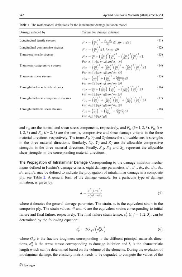
and τ13 are the normal and shear stress components, respectively, and FiT (i = 1, 2, 3), FiC (i =1, 2, 3) and FiS (i = 2, 3) are the tensile, compressive and shear damage criteria in the threematerial directions, respectively. The terms XT, YT and ZT denote the allowable tensile strengthsin the three material directions. Similarly, XC, YC and ZC are the allowable compressivestrengths in the three material directions. Finally, S12, S13 and S23 represent the allowableshear strengths in the corresponding material directions.
The Propagation of Intralaminar Damage Corresponding to the damage initiation mecha-nisms defined in Hashin’s damage criteria, eight damage parameters, d1t, d1c, d2t, d2c, d2s, d3t,d3c and d3s may be defined to indicate the propagation of intralaminar damage in a compositeply, see Table 2. A general form of the damage variable, for a particular type of damageinitiation, is given by:
d ¼ ε f ε−ε0ð Þε ε f −ε0ð Þ ð5Þ
where d denotes the general damage parameter. The strain, ε, is the equivalent strain in thecomposite ply. The strain values, ε0 and εf, are the equivalent strains corresponding to initial
failure and final failure, respectively. The final failure strain tensor, ε fij i; j ¼ 1; 2; 3ð Þ, can be
determined by the following equation:
ε fij ¼ 2Gcij= σ0ijlc� �
ð6Þ
where Gcij is the fracture toughness corresponding to the different principal materials direc-tions, σ0ij is the stress tensor corresponding to damage initiation and lc is the characteristic
length which can be determined based on the volume of the elements. During the evolution ofintralaminar damage, the elasticity matrix needs to be degraded to compute the values of the
Table 1 The mathematical definitions for the intralaminar damage initiation model
Damage induced by Criteria for damage initiation
Longitudinal tensile stressesF1T ¼ σ11
XT
� �2þ σ212þσ213
S212≤1; for σ11≥0
(11)
Longitudinal compressive stressesF1C ¼ σ11
XC
� �2≤1; for σ11≤0
(12)
Transverse tensile stressesF2T ¼ σ22
YTþ E22
2G12
� �2τ12YT
� �2þ E22
2G23
� �2τ23YT
� �2≤1;
For |σ22| ≥ |τ12(τ23)| and σ22 ≥ 0
(13)
Transverse compressive stressesF2C ¼ σ22
YC
� �2þ E22
G12
� �2τ12YC
� �2þ E22
G23
� �2τ23YC
� �2≤1
For |σ22| ≥ |τ12(τ23)| and σ22 ≤ 0
(14)
Transverse shear stressesF2S ¼ τ12
S12
� �2þ τ23
S23
� �2þ 2G12
E22
σ22YC
≤1For |σ33| ≥ |τ13(τ23)| and σ33 ≥ 0
(15)
Through-thickness tensile stressesF3T ¼ σ33
ZTþ E33
2G13
� �2τ13ZT
� �2þ E33
2G23
� �2τ23ZT
� �2≤1
For |σ33| ≥ |τ13(τ23)| and σ33 ≥ 0
(16)
Through-thickness compressive stressesF3C ¼ σ33
ZC
� �2þ E33
G13
� �2τ13ZC
� �2þ E33
G23
� �2τ23YC
� �2≤1
For |σ33| ≥ |τ13(τ23)| and σ33 ≤ 0
(17)
Through-thickness shear stressesF3S ¼ τ13
S13
� �2þ τ23
S23
� �2þ 2G13
E33
σ33ZC≤1
For |σ33| ≤ |τ13(τ23)|
(18)
Applied Composite Materials (2020) 27:533–553542
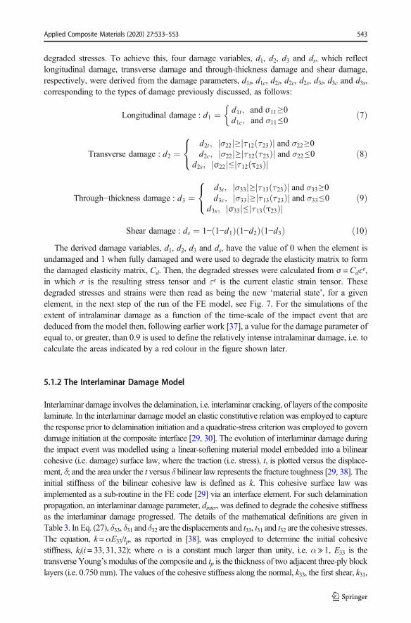
degraded stresses. To achieve this, four damage variables, d1, d2, d3 and ds, which reflectlongitudinal damage, transverse damage and through-thickness damage and shear damage,respectively, were derived from the damage parameters, d1t, d1c, d2t, d2c, d2s, d3t, d3c and d3s,corresponding to the types of damage previously discussed, as follows:
Longitudinal damage : d1 ¼ d1t; and σ11≥0d1c; and σ11≤0
�ð7Þ
Transverse damage : d2 ¼d2t; σ22j j≥ τ12 τ23ð Þj j and σ22≥0d2c; σ22j j≥ τ12 τ23ð Þj j and σ22≤0
d2s; σ22j j≤ τ12 τ23ð Þj j
8<: ð8Þ
Through−thickness damage : d3 ¼d3t; σ33j j≥ τ13 τ23ð Þj j and σ33≥0d3c; σ33j j≥ τ13 τ23ð Þj j and σ33≤0
d3s; σ33j j≤ τ13 τ23ð Þj j
8<: ð9Þ
Shear damage : ds ¼ 1− 1−d1ð Þ 1−d2ð Þ 1−d3ð Þ ð10ÞThe derived damage variables, d1, d2, d3 and ds, have the value of 0 when the element is
undamaged and 1 when fully damaged and were used to degrade the elasticity matrix to formthe damaged elasticity matrix, Cd. Then, the degraded stresses were calculated from σ =Cdεe,in which σ is the resulting stress tensor and εe is the current elastic strain tensor. Thesedegraded stresses and strains were then read as being the new ‘material state’, for a givenelement, in the next step of the run of the FE model, see Fig. 7. For the simulations of theextent of intralaminar damage as a function of the time-scale of the impact event that arededuced from the model then, following earlier work [37], a value for the damage parameter ofequal to, or greater, than 0.9 is used to define the relatively intense intralaminar damage, i.e. tocalculate the areas indicated by a red colour in the figure shown later.
5.1.2 The Interlaminar Damage Model
Interlaminar damage involves the delamination, i.e. interlaminar cracking, of layers of the compositelaminate. In the interlaminar damage model an elastic constitutive relation was employed to capturethe response prior to delamination initiation and a quadratic-stress criterion was employed to governdamage initiation at the composite interface [29, 30]. The evolution of interlaminar damage duringthe impact event was modelled using a linear-softening material model embedded into a bilinearcohesive (i.e. damage) surface law, where the traction (i.e. stress), t, is plotted versus the displace-ment, δ; and the area under the t versus δ bilinear law represents the fracture toughness [29, 38]. Theinitial stiffness of the bilinear cohesive law is defined as k. This cohesive surface law wasimplemented as a sub-routine in the FE code [29] via an interface element. For such delaminationpropagation, an interlaminar damage parameter, dinter, was defined to degrade the cohesive stiffnessas the interlaminar damage progressed. The details of the mathematical definitions are given inTable 3. In Eq. (27), δ33, δ31 and δ32 are the displacements and t33, t31 and t32 are the cohesive stresses.The equation, k=αE33/tp, as reported in [38], was employed to determine the initial cohesivestiffness, ki(i= 33, 31, 32); where α is a constant much larger than unity, i.e. α≫ 1, E33 is thetransverse Young’s modulus of the composite and tp is the thickness of two adjacent three-ply blocklayers (i.e. 0.750 mm). The values of the cohesive stiffness along the normal, k33, the first shear, k31,
Applied Composite Materials (2020) 27:533–553 543
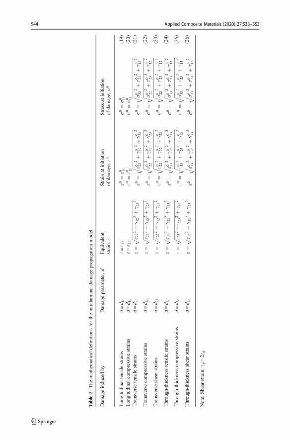
Table2
The
mathematicaldefinitio
nsfortheintralam
inar
damagepropagationmodel
Dam
ageinducedby
Dam
ageparameter,d
Equivalent
strain,ε
Strain
atinitiation
ofdamage,ε0
Stress
atinitiation
ofdamage,σ0
Longitudinaltensile
strains
d=d 1
tε=ε 1
1ε0
¼ε0 11
σ0¼
σ0 11
(19)
Longitudinalcompressive
strains
d=d 1
cε=ε 1
1ε0
¼ε0 11
σ0¼
σ0 11
(20)
Transversetensile
strains
d=d 2
tε¼
ffiffiffiffiffiffiffiffiffiffiffiffi
ffiffiffiffiffiffiffiffiffiffiffiffi
ffiffiffiffiffiffiffiffiffiffiffiffi
ε 222þγ12
2þγ23
2p
ε0¼
ffiffiffiffiffiffiffiffiffiffiffiffi
ffiffiffiffiffiffiffiffiffiffiffiffi
ffiffiffiffiffiffiffiffiffiffiffiffi
ε0 222þγ0 12
2þγ0 23
2q
σ0¼
ffiffiffiffiffiffiffiffiffiffiffiffi
ffiffiffiffiffiffiffiffiffiffiffiffi
ffiffiffiffiffiffiffiffiffiffiffiffiffi
σ0 22
2þτ0 23
2þτ0 12
2q
(21)
Transversecompressive
strains
d=d 2
cε¼
ffiffiffiffiffiffiffiffiffiffiffiffi
ffiffiffiffiffiffiffiffiffiffiffiffi
ffiffiffiffiffiffiffiffiffiffiffiffi
ε 222þγ12
2þγ23
2p
ε0¼
ffiffiffiffiffiffiffiffiffiffiffiffi
ffiffiffiffiffiffiffiffiffiffiffiffi
ffiffiffiffiffiffiffiffiffiffiffiffi
ε0 222þγ0 12
2þγ0 23
2q
σ0¼
ffiffiffiffiffiffiffiffiffiffiffiffi
ffiffiffiffiffiffiffiffiffiffiffiffi
ffiffiffiffiffiffiffiffiffiffiffiffiffi
σ0 22
2þτ0 23
2þτ0 12
2q
(22)
Transverseshearstrains
d=d 2
sε¼
ffiffiffiffiffiffiffiffiffiffiffiffi
ffiffiffiffiffiffiffiffiffiffiffiffi
ffiffiffiffiffiffiffiffiffiffiffiffi
ε 222þγ12
2þγ23
2p
ε0¼
ffiffiffiffiffiffiffiffiffiffiffiffi
ffiffiffiffiffiffiffiffiffiffiffiffi
ffiffiffiffiffiffiffiffiffiffiffiffi
ε0 222þγ0 12
2þγ0 23
2q
σ0¼
ffiffiffiffiffiffiffiffiffiffiffiffi
ffiffiffiffiffiffiffiffiffiffiffiffi
ffiffiffiffiffiffiffiffiffiffiffiffiffi
σ0 22
2þτ0 23
2þτ0 12
2q
(23)
Through-thickness
tensile
strains
d=d 3
tε¼
ffiffiffiffiffiffiffiffiffiffiffiffi
ffiffiffiffiffiffiffiffiffiffiffiffi
ffiffiffiffiffiffiffiffiffiffiffiffi
ε 332þγ23
2þγ13
2p
ε0¼
ffiffiffiffiffiffiffiffiffiffiffiffi
ffiffiffiffiffiffiffiffiffiffiffiffi
ffiffiffiffiffiffiffiffiffiffiffiffi
ε0 332þγ0 23
2þγ0 13
2q
σ0¼
ffiffiffiffiffiffiffiffiffiffiffiffi
ffiffiffiffiffiffiffiffiffiffiffiffi
ffiffiffiffiffiffiffiffiffiffiffiffiffi
σ0 33
2þτ0 23
2þτ0 13
2q
(24)
Through-thickness
compressive
strains
d=d 3
cε¼
ffiffiffiffiffiffiffiffiffiffiffiffi
ffiffiffiffiffiffiffiffiffiffiffiffi
ffiffiffiffiffiffiffiffiffiffiffiffi
ε 332þγ23
2þγ13
2p
ε0¼
ffiffiffiffiffiffiffiffiffiffiffiffi
ffiffiffiffiffiffiffiffiffiffiffiffi
ffiffiffiffiffiffiffiffiffiffiffiffi
ε0 332þγ0 23
2þγ0 13
2q
σ0¼
ffiffiffiffiffiffiffiffiffiffiffiffi
ffiffiffiffiffiffiffiffiffiffiffiffi
ffiffiffiffiffiffiffiffiffiffiffiffiffi
σ0 33
2þτ0 23
2þτ0 13
2q
(25)
Through-thickness
shearstrains
d=d 3
sε¼
ffiffiffiffiffiffiffiffiffiffiffiffi
ffiffiffiffiffiffiffiffiffiffiffiffi
ffiffiffiffiffiffiffiffiffiffiffiffi
ε 332þγ23
2þγ13
2p
ε0¼
ffiffiffiffiffiffiffiffiffiffiffiffi
ffiffiffiffiffiffiffiffiffiffiffiffi
ffiffiffiffiffiffiffiffiffiffiffiffi
ε0 332þγ0 23
2þγ0 13
2q
σ0¼
ffiffiffiffiffiffiffiffiffiffiffiffi
ffiffiffiffiffiffiffiffiffiffiffiffi
ffiffiffiffiffiffiffiffiffiffiffiffiffi
σ0 33
2þτ0 23
2þτ0 13
2q
(26)
Note:Sh
earstrain,γ
ij=2ε
ij
Applied Composite Materials (2020) 27:533–553544
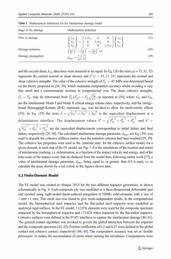
and the second shear, k32, directions were assumed to be equal. In Eq. (28) the term ti(i= 33, 31, 32)represents the current normal or shear stresses and t0i i ¼ 33; 31; 32ð Þ represents the normal andshear cohesive strengths. The value of the cohesive strength of t033 ¼ 43 MPa was determined basedon the theory proposed in [38, 39], which maintains computation accuracy whilst avoiding a veryfine mesh and a commensurate increase in computational cost. The shear cohesive strengths,
t031 ¼ t032, may be determined from t031 t032� � ¼ t033
ffiffiffiffiffiGIIcGIc
q, as reported in [39], where GIc and GIIc
are the interlaminar Mode I and Mode II critical energy release rates, respectively, and the energy-based Benzeggagh-Kenane (B-K) exponent, ηBK, was invoked to allow for mode-mixity effects
[39]. In Eq. (29) the term δ ¼ffiffiffiffiffiffiffiffiffiffiffiffiffiffiffiffiffiffiffiffiffiffiffiffiffiffiffiffiffiffiffiffiffiffiffiδ33
2 þ δ312 þ δ32
2p
is the equivalent displacement at a
delamination interface. The displacement values δ0 ¼ffiffiffiffiffiffiffiffiffiffiffiffiffiffiffiffiffiffiffiffiffiffiffiffiffiffiffiffiffiffiffiffiffiffiffiδ033
2 þ δ0312 þ δ032
2q
and δ f ¼ffiffiffiffiffiffiffiffiffiffiffiffiffiffiffiffiffiffiffiffiffiffiffiffiffiffiffiffiffiffiffiffiffiffiffiδ f33
2 þ δ f312 þ δ f32
2q
are the equivalent displacements corresponding to initial failure and final
failure, respectively [29, 39]. The calculated interlaminar damage parameter, dinter, see Eq. (29), wasused to degrade the cohesive stiffness matrix once the initiation criterion had been reached [29, 39].The cohesive law properties were used as the ‘material state’ for the cohesive surface model, for agiven element, in each step of the FEmodel, see Fig. 7. For the simulations of the location and extentof interlaminar cracking, i.e. delamination, as a function of the impact velocity and energy, and of thetime-scale of the impact event, that are deduced from the model then, following earlier work [37], avalue of interlaminar damage parameter, dinter, being equal to, or greater, than 0.9 is used, i.e. tocalculate the areas shown by a red colour in the figures shown later.
5.2 Finite-Element Model
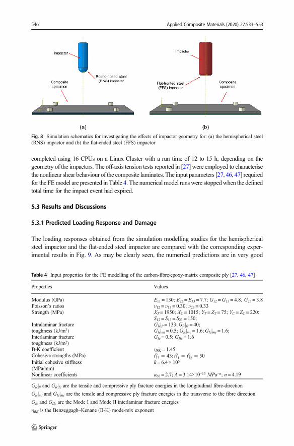
The FE model was created in Abaqus 2018 for the two different impactor geometries, as shownschematically in Fig. 8. Each composite ply was modelled as a three-dimensional deformable partand meshed using eight-noded linear-reduced integration (C3D8R) solid-elements with a size of1 mm× 1 mm. This mesh size was found to give mesh-independent results. In the computationalmodel, the hemispherical steel impactor and the flat-ended steel impactor were modelled asanalytical rigid surfaces. In the FE model, 112,076 elements were used for the composite specimenimpacted by the hemispherical impactor and 113,024 when impacted by the flat-ended impactor.Cohesive surfaces were defined at the 0o/45o interfaces to capture the interlaminar damage [40, 41].The general contact algorithm was invoked to govern the global interaction between the impactorand the composite specimen [42, 43]. Friction coefficients of 0.2 and 0.25were defined in the globalcontact and cohesive contact, respectively [44, 45]. The computation accuracy was set as ‘doubleprecession’ to reduce the accumulation of errors when running the simulation. Computations were
Table 3 Mathematical definitions for the interlaminar damage model
Stage of the damage Mathematical definition
Prior to damage δ33δ31δ32
8<:
9=; ¼
1=k33 0 00 1=k31 00 0 1=k32
24
35 t33
t31t32
8<:
9=;
(27)
Damage initiation t33h it033
� �2þ t31
t031
� �2þ t32
t032
� �2≥1 (28)
Damage propagation dinter ¼ δ f δ−δ0ð Þδ δ f −δ0ð Þ
(29)
Applied Composite Materials (2020) 27:533–553 545
completed using 16 CPUs on a Linux Cluster with a run time of 12 to 15 h, depending on thegeometry of the impactors. The off-axis tension tests reported in [27] were employed to characterisethe nonlinear shear behaviour of the composite laminates. The input parameters [27, 46, 47] requiredfor the FEmodel are presented in Table 4. The numericalmodel runswere stoppedwhen the definedtotal time for the impact event had expired.
5.3 Results and Discussions
5.3.1 Predicted Loading Response and Damage
The loading responses obtained from the simulation modelling studies for the hemisphericalsteel impactor and the flat-ended steel impactor are compared with the corresponding exper-imental results in Fig. 9. As may be clearly seen, the numerical predictions are in very good
Fig. 8 Simulation schematics for investigating the effects of impactor geometry for: (a) the hemispherical steel(RNS) impactor and (b) the flat-ended steel (FFS) impactor
Table 4 Input properties for the FE modelling of the carbon-fibre/epoxy-matrix composite ply [27, 46, 47]
Properties Values
Modulus (GPa) E11 = 130; E22 = E33 = 7.7; G12 =G13 = 4.8; G23 = 3.8Poisson’s ratios ν12 = ν13 = 0.30; ν23 = 0.33Strength (MPa) XT = 1950; XC = 1015; YT = ZT = 75; YC = ZC = 220;
S12 = S13 = S23 = 150;Intralaminar fracturetoughness (kJ/m2)
GIc|ft = 133;GIc|fc = 40;GIc|mt = 0.5; GIc|mc = 1.6;GIc|ms = 1.6;
Interlaminar fracturetoughness (kJ/m2)
GIc = 0.5; GIIc = 1.6
B-K coefficient ηBK = 1.45Cohesive strengths (MPa) t033 ¼ 43; t031 ¼ t032 ¼ 50Initial cohesive stiffness(MPa/mm)
k = 6.4 × 10⁵
Nonlinear coefficients a66 = 2.7; A = 3.14×10⁻¹³ MPa−n; n = 4.19
GIc|ft and GIc|fc are the tensile and compressive ply fracture energies in the longitudinal fibre-direction
GIc|mt and GIc|mc are the tensile and compressive ply fracture energies in the transverse to the fibre direction
GIc and GIIc are the Mode I and Mode II interlaminar fracture energies
ηBK is the Benzeggagh–Kenane (B-K) mode-mix exponent
Applied Composite Materials (2020) 27:533–553546
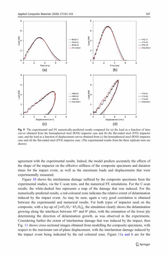
agreement with the experimental results. Indeed, the model predicts accurately the effects ofthe shape of the impactor on the effective stiffness of the composite specimens and durationtimes for the impact event, as well as the maximum loads and displacements that wereexperimentally measured.
Figure 10 shows the interlaminar damage suffered by the composite specimens from theexperimental studies, via the C-scan tests, and the numerical FE simulations. For the C-scanresults, the white-dashed line represents a map of the damage that was induced. For thenumerically-predicted results, a red-coloured zone indicates the relative extent of delaminationinduced by the impact event. As may be seen, again a very good correlation is obtainedbetween the experimental and numerical results. For both types of impactor used on thecomposite, with a lay-up of [+453/03/−453/03]s, the simulation clearly shows the delaminationgrowing along the interfaces between 45o and 0o plies, with the orientation of the lower plydetermining the direction of delamination growth, as was observed in the experiments.Considering further the extent of interlaminar damage that was induced by the impact, thenFig. 11 shows cross-sectional images obtained from modelling the composite specimens, withrespect to the maximum out-of-plane displacement, with the interlaminar damage induced bythe impact event being indicated by the red coloured zone. Figure 11a and b are for the
Fig. 9 The experimental and FE numerically-predicted results compared for (a) the load as a function of timecurves obtained from the hemispherical steel (RNS) impactor case and (b) the flat-ended steel (FFS) impactorcase; and the load as a function of displacement curves obtained from (c) the hemispherical steel (RNS) impactorcase and (d) the flat-ended steel (FFS) impactor case. (The experimental results from the three replicate tests areshown)
Applied Composite Materials (2020) 27:533–553 547
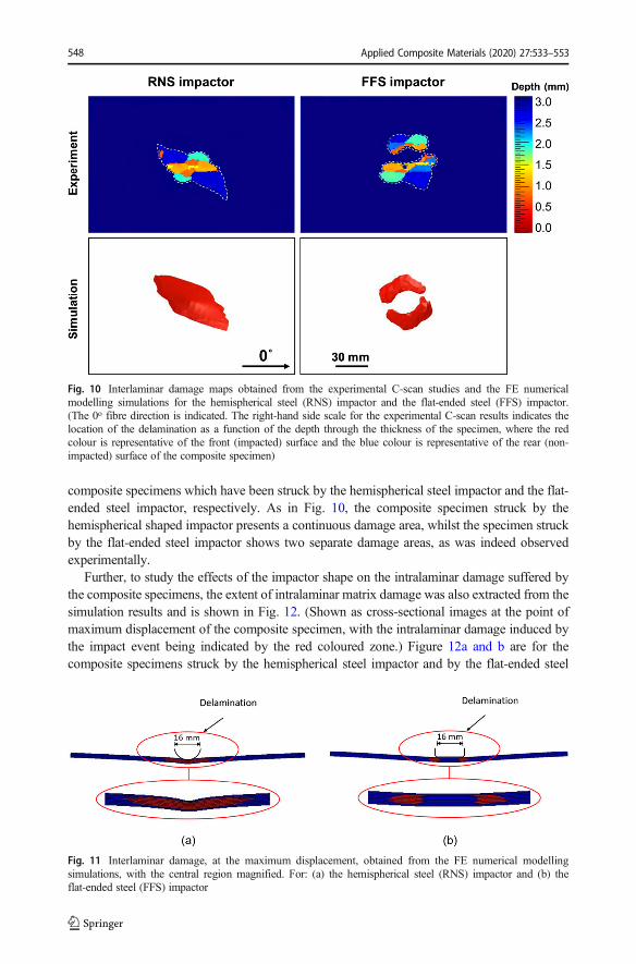
composite specimens which have been struck by the hemispherical steel impactor and the flat-ended steel impactor, respectively. As in Fig. 10, the composite specimen struck by thehemispherical shaped impactor presents a continuous damage area, whilst the specimen struckby the flat-ended steel impactor shows two separate damage areas, as was indeed observedexperimentally.
Further, to study the effects of the impactor shape on the intralaminar damage suffered bythe composite specimens, the extent of intralaminar matrix damage was also extracted from thesimulation results and is shown in Fig. 12. (Shown as cross-sectional images at the point ofmaximum displacement of the composite specimen, with the intralaminar damage induced bythe impact event being indicated by the red coloured zone.) Figure 12a and b are for thecomposite specimens struck by the hemispherical steel impactor and by the flat-ended steel
Fig. 10 Interlaminar damage maps obtained from the experimental C-scan studies and the FE numericalmodelling simulations for the hemispherical steel (RNS) impactor and the flat-ended steel (FFS) impactor.(The 0o fibre direction is indicated. The right-hand side scale for the experimental C-scan results indicates thelocation of the delamination as a function of the depth through the thickness of the specimen, where the redcolour is representative of the front (impacted) surface and the blue colour is representative of the rear (non-impacted) surface of the composite specimen)
Fig. 11 Interlaminar damage, at the maximum displacement, obtained from the FE numerical modellingsimulations, with the central region magnified. For: (a) the hemispherical steel (RNS) impactor and (b) theflat-ended steel (FFS) impactor
Applied Composite Materials (2020) 27:533–553548
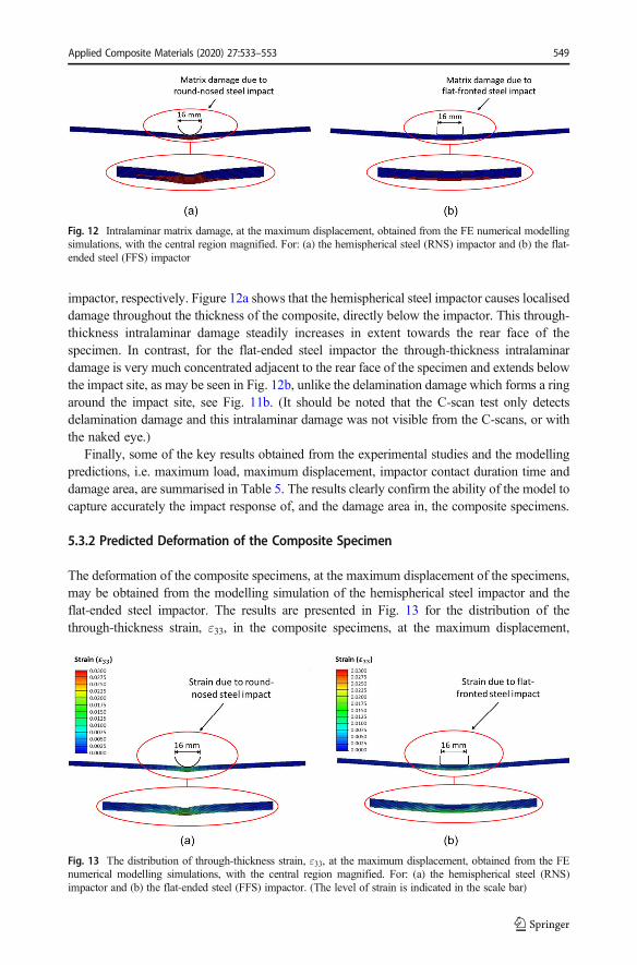
impactor, respectively. Figure 12a shows that the hemispherical steel impactor causes localiseddamage throughout the thickness of the composite, directly below the impactor. This through-thickness intralaminar damage steadily increases in extent towards the rear face of thespecimen. In contrast, for the flat-ended steel impactor the through-thickness intralaminardamage is very much concentrated adjacent to the rear face of the specimen and extends belowthe impact site, as may be seen in Fig. 12b, unlike the delamination damage which forms a ringaround the impact site, see Fig. 11b. (It should be noted that the C-scan test only detectsdelamination damage and this intralaminar damage was not visible from the C-scans, or withthe naked eye.)
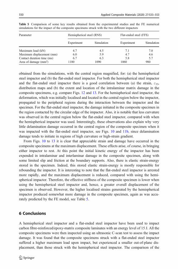
Finally, some of the key results obtained from the experimental studies and the modellingpredictions, i.e. maximum load, maximum displacement, impactor contact duration time anddamage area, are summarised in Table 5. The results clearly confirm the ability of the model tocapture accurately the impact response of, and the damage area in, the composite specimens.
5.3.2 Predicted Deformation of the Composite Specimen
The deformation of the composite specimens, at the maximum displacement of the specimens,may be obtained from the modelling simulation of the hemispherical steel impactor and theflat-ended steel impactor. The results are presented in Fig. 13 for the distribution of thethrough-thickness strain, ε33, in the composite specimens, at the maximum displacement,
Fig. 13 The distribution of through-thickness strain, ε33, at the maximum displacement, obtained from the FEnumerical modelling simulations, with the central region magnified. For: (a) the hemispherical steel (RNS)impactor and (b) the flat-ended steel (FFS) impactor. (The level of strain is indicated in the scale bar)
Fig. 12 Intralaminar matrix damage, at the maximum displacement, obtained from the FE numerical modellingsimulations, with the central region magnified. For: (a) the hemispherical steel (RNS) impactor and (b) the flat-ended steel (FFS) impactor
Applied Composite Materials (2020) 27:533–553 549
obtained from the simulations, with the central region magnified, for: (a) the hemisphericalsteel impactor and (b) the flat-ended steel impactor. For both the hemispherical steel impactorand the flat-ended steel impactor there is a good correlation between (a) the strain, ε33,distribution maps and (b) the extent and location of the intralaminar matrix damage in thecomposite specimens, e.g. compare Figs. 12 and 13. For the hemispherical steel impactor, thedeformation, which was initially localised and located in the central region below the impactor,propagated to the peripheral regions during the interaction between the impactor and thespecimen. For the flat-ended steel impactor, the damage initiated in the composite specimen inthe region contacted by the circular edge of the impactor. Also, it is notable that less curvaturewas observed in the central region below the flat-ended steel impactor, compared with whenthe hemispherical impactor was used. Interestingly, these observations also explain why verylittle delamination damage occurred in the central region of the composite specimen when itwas impacted with the flat-ended steel impactor, see Figs. 10 and 11b, since delaminationdamage tends to initiate in regions of high curvature or high-strain gradient.
From Figs. 10 to 13 it is clear that appreciable strain and damage have occurred in thecomposite specimens at the maximum displacement. These effects arise, of course, in bringingeither impactor to rest. At this point the initial kinetic energy of the impactor has beenexpended in intralaminar and interlaminar damage in the composite specimen, along withsome limited slip and friction at the boundary supports. Also, there is elastic strain-energystored in the specimen. Indeed, this stored elastic strain-energy is mostly responsible forrebounding the impactor. It is interesting to note that the flat-ended steel impactor is arrestedmore rapidly, and the maximum displacement is reduced, compared with using the hemi-spherical impactor. Therefore, the effective stiffness of the composite specimen is lower whenusing the hemispherical steel impactor and, hence, a greater overall displacement of thespecimen is observed. However, the higher localised strains generated by the hemisphericalimpactor produced somewhat more damage in the composite specimen, again as was accu-rately predicted by the FE model, see Table 5.
6 Conclusions
A hemispherical steel impactor and a flat-ended steel impactor have been used to impactcarbon fibre-reinforced/epoxy-matrix composite laminates with an energy level of 15 J. All thecomposite specimens were then inspected using an ultrasonic C-scan test to assess the impactdamage. It was found that the composite specimens struck with a flat-ended steel impactorsuffered a higher maximum load upon impact, but experienced a smaller out-of-plane dis-placement, than those struck with the hemispherical steel impactor. The comparison of the
Table 5 Comparison of some key results obtained from the experimental studies and the FE numericalsimulations for the impact of the composite specimens struck with the two different impactors
Parameter Hemispherical steel (RNS) Flat-ended steel (FFS)
Experiment Simulation Experiment Simulation
Maximum load (kN) 4.7 4.5 7.1 7.0Maximum displacement (mm) 6.0 5.9 4.7 4.6Contact duration time (ms) 6.7 6.3 5.8 5.7Area of damage (mm2) 1180 1090 1060 980
Applied Composite Materials (2020) 27:533–553550
experimental C-scan images showed that the delamination maps of the composite specimensimpacted with the hemispherical steel and the flat-ended steel impactors were similar in areabut with somewhat more areal damage occurring when the hemispherical steel impactor wasused. However, the composite specimens impacted with the hemispherical steel impactorshowed a continuous delamination area, which was centred around the point of impact, whilstthe flat-ended steel impacted specimens exhibited two separate delamination areas, with acentral zone exhibiting no delamination. To further understand the effects of the geometry ofthe impactor head, a three-dimensional, finite-element (FE) computational model was devel-oped to simulate the impact response of the composite laminates when struck with the twodifferent types of impactor. It was found that the FE numerical simulations, with an embeddedelastic-plastic damage model for the material response, very accurately predicted the keyparameters of the impact event, such as (a) the shape and area of the delamination, (b) themaximum load and displacement, and (c) the duration time of the impact event. Furthermore,these numerical simulations have explained the underlying reasons for the effects of the shapeof the impactor head on the impact behaviour of the composite specimens. These studies have,therefore, increased our understanding of the behaviour of composite laminates when subject-ed to a relatively low-velocity impact and have proposed, and validated, an elastic-plasticthree-dimensional FE numerical model for predicting the response of the laminate. This modelwill play a significant role in future academic research and industrial applications with respectto predicting and improving the impact behaviour of composite laminates.
Acknowledgements This paper was presented at the 3rd International Conference on Structural Integrity, 2nd–5th September 2019, Funchal, Madeira organised by Professor Pedro Moreira and Professor Paulo Tavares. Thestrong support from the Aviation Industry Corporation of China (AVIC) Manufacturing Technology Institute(MTI) in China, the First Aircraft Institute (FAI) in China and the Aircraft Strength Research Institute (ASRI) inChina for this funded research is much appreciated. The research was performed at the AVIC Centre forStructural Design and Manufacture at Imperial College London, UK. The authors are very grateful for usefuldiscussions with Professor Jianguo Lin, FREng of Imperial College London.
Open Access This article is licensed under a Creative Commons Attribution 4.0 International License, whichpermits use, sharing, adaptation, distribution and reproduction in any medium or format, as long as you giveappropriate credit to the original author(s) and the source, provide a link to the Creative Commons licence, andindicate if changes were made. The images or other third party material in this article are included in the article'sCreative Commons licence, unless indicated otherwise in a credit line to the material. If material is not includedin the article's Creative Commons licence and your intended use is not permitted by statutory regulation orexceeds the permitted use, you will need to obtain permission directly from the copyright holder. To view a copyof this licence, visit http://creativecommons.org/licenses/by/4.0/.
References
1. Roeseler B, Sarh B, Kismarton M. Composite Structures – The First 100 Years. Boeing 787 Progr ComposDes Tutor, 2009:1–41
2. Liu, H., Falzon, B.G., Catalanotti, G., Tan, W.: An experimental method to determine the intralaminarfracture toughness of high-strength carbon-fibre reinforced composite aerostructures. Aeronaut. J. 122,1352–1370 (2018)
3. Tehrani, M., Boroujeni, Y., Hartman, T.B., Haugh, T.P., Case, S.W., Al-Haik, M.S.: Mechanical charac-terization and impact damage assessment of a woven carbon fiber reinforced carbon nanotube-epoxycomposite. Compos. Sci. Technol. 75, 42–48 (2013)
4. Elder, D.J., Thomson, R.S., Nguyen, M.Q., Scott, M.L.: Review of delamination predictive methods for lowspeed impact of composite laminates. Compos. Struct. 66, 677–683 (2004)
Applied Composite Materials (2020) 27:533–553 551
5. Liu, H., Falzon, B.G., Tan, W.: Experimental and numerical studies on the impact response of damage-tolerant hybrid unidirectional/woven carbon-fibre reinforced composite laminates. Compos Part B Eng. 136,101–118 (2018)
6. Donadon, M.V., Iannucci, L., Falzon, B.G., Hodgkinson, J.M., De Almeida, S.F.M.: A progressive failure modelfor composite laminates subjected to low velocity impact damage. Comput. Struct. 86, 1232–1252 (2008)
7. Liu, H., Falzon, B.G., Tan, W.: Predicting the compression-after-impact (CAI) strength of damage-toleranthybrid unidirectional/woven carbon-fibre reinforced composite laminates. Compos Part A Appl Sci Manuf.105, 189–202 (2018)
8. Rivallant, S., Bouvet, C., Abi Abdallah, E., Broll, B., Barrau, J.J.: Experimental analysis of CFRP laminatessubjected to compression after impact: the role of impact-induced cracks in failure. Compos. Struct. 111,147–157 (2014)
9. Eyer, G., Montagnier, O., Hochard, C., Charles, J.: Effect of matrix damage on compressive strength in thefiber direction for laminated composites. Compos Part A Appl Sci Manuf. 94, 86–92 (2017)
10. De Freitas, M., Reis, L.: Failure mechanisms on composite specimens subjected to compression afterimpact. Compos. Struct. 42, 365–373 (1998)
11. Borg, R., Nilsson, L., Simonsson, K.: Simulation of low velocity impact on fiber laminates using a cohesivezone based delamination model. Compos. Sci. Technol. 64, 279–288 (2004)
12. Raimondo, L., Iannucci, L., Robinson, P., Curtis, P.T.: A progressive failure model for mesh-size-independent FE analysis of composite laminates subject to low-velocity impact damage. Compos. Sci.Technol. 72, 624–632 (2012)
13. Israr, H.A., Rivallant, S., Bouvet, C., Barrau, J.J.: Finite element simulation of 0/90 CFRP laminated platessubjected to crushing using a free-face-crushing concept. Compos Part A Appl Sci Manuf. 62, 16–25 (2014)
14. González, E.V., Maimí, P., Camanho, P.P., Turon, A., Mayugo, J.A.: Simulation of drop-weight impact andcompression after impact tests on composite laminates. Compos. Struct. 94, 3364–3378 (2012)
15. Petit, S., Bouvet, C., Bergerot, A., Barrau, J.J.: Impact and compression after impact experimental study of acomposite laminate with a cork thermal shield. Compos. Sci. Technol. 67, 3286–3299 (2007)
16. Rivallant, S., Bouvet, C., Hongkarnjanakul, N.: Failure analysis of CFRP laminates subjected to compres-sion after impact: FE simulation using discrete interface elements. Compos Part A Appl Sci Manuf. 55, 83–93 (2013)
17. Mitrevski, T., Marshall, I.H., Thompson, R., Jones, R., Whittingham, B.: The effect of impactor shape onthe impact response of composite laminates. Compos. Struct. 67, 139–148 (2005)
18. Mitrevski, T., Marshall, I.H., Thompson, R.: The influence of impactor shape on the damage to compositelaminates. Compos. Struct. 76, 116–122 (2006)
19. Robinson, P., Davies, G.A.O.: Impactor mass and specimen geometry effects in low velocity impact oflaminated composites. Int J Impact Eng. 12, 189–207 (1992)
20. Sevkat, E., Liaw, B., Delale, F.: Drop-weight impact response of hybrid composites impacted by impactorof various geometries. Mater & Design. 52, 67–77 (2013)
21. Olsson, R.: Analytical prediction of large mass impact damage in composite laminates. Compos Part AAppl Sci Manuf. 32, 1207–1215 (2001)
22. Olsson, R.: Analytical model for delamination growth during small mass impact on plates. Int. J. SolidsStruct. 47, 2884–2892 (2010)
23. Bouvet, C., Rivallant, S., Barrau, J.J.: Low velocity impact modeling in composite laminates capturingpermanent indentation. Compos. Sci. Technol. 72, 1977–1988 (2012)
24. Bouvet, C., Castanié, B., Bizeul, M., Barrau, J.J.: Low velocity impact modelling in laminate compositepanels with discrete interface elements. Int. J. Solids Struct. 46, 2809–2821 (2009)
25. ASTM. Standard Test Method for Measuring the Damage Resistance of a Fiber-Reinforced Polymer MatrixComposite to a Drop-Weight Impact Event. D7136, West Conshohocken, PA, USA, 2014
26. Liu, J., Liu, H., Kaboglu, C., Kong, X., Ding, Y., Chai, H., Blackman, B.R.K., Kinloch, A.J., Dear, J.P.:The impact performance of woven-fabric thermoplastic and thermoset composites subjected to high-velocitysoft- and hard-impact loading. Appl. Compos. Mater. 26, 1389–1410 (2019)
27. Yokozeki, T., Ogihara, S., Yoshida, S., Ogasawara, T.: Simple constitutive model for nonlinear response offiber-reinforced composites with loading-directional dependence. Compos. Sci. Technol. 67, 111–118(2007)
28. Gates, T.S., Sun, C.T.: Elastic/viscoplastic constitutive model for fiber reinforced thermoplastic composites.AIAA J. 29, 457–463 (1991)
29. Abaqus 2018 documentation. Dassault Systèmes. Provid Rhode Island, USA, 201830. Chen, J.K., Allahdadi, F.A., Sun, C.T.: A quadratic yield function for fiber-reinforced composites. J.
Compos. Mater. 31, 788–811 (1997)31. Sun, C.T., Chen, J.L.: A simple flow rule for characterizing nonlinear behavior of fiber composites. J.
Compos. Mater. 23, 1009–1020 (1989)
Applied Composite Materials (2020) 27:533–553552
32. Sun, C.T., Rui, Y.: Orthotropic elasto-plastic behavior of AS4/PEEK thermoplastic composite in compres-sion. Mech. Mater. 10, 117–125 (1990)
33. Yoon, K.J., Sun, C.T.: Characterization of elastic-viscoplastic properties of an AS4/PEEK thermoplasticcomposite. J. Compos. Mater. 25, 1277–1296 (1991)
34. Daniel, I.M., Luo, J.J., Schubel, P.M.: Three-dimensional characterization of textile composites. ComposPart B Eng. 39, 13–19 (2008)
35. Daniel, I.M., Luo, J.J., Schubel, P.M., Werner, B.T.: Interfiber/interlaminar failure of composites undermulti-axial states of stress. Compos. Sci. Technol. 69, 764–771 (2009)
36. Daniel, I.M.: Failure of composite materials. Strain. 43, 4–12 (2007)37. Faggiani, A., Falzon, B.G.: Predicting low-velocity impact damage on a stiffened composite panel. Compos
Part A Appl Sci Manuf. 41, 737–749 (2010)38. Turon, A., Dávila, C.G., Camanho, P.P., Costa, J.: An engineering solution for mesh size effects in the
simulation of delamination using cohesive zone models. Eng. Fract. Mech. 74, 1665–1682 (2007)39. Turon, A., Camanho, P.P., Costa, J., Renart, J.: Accurate simulation of delamination growth under mixed-
mode loading using cohesive elements: definition of interlaminar strengths and elastic stiffness. Compos.Struct. 92, 1857–1864 (2010)
40. Liu, H., Liu, J., Kaboglu, C., Chai, H., Kong, X., Blackman, B.R.K., Kinloch, A.J., Dear, J.P.: Experimentalinvestigations on the effects of projectile hardness on the impact response of fibre reinforced compositelaminates. Int J Light Mater Manuf. 3, 77–87 (2020)
41. Liu, H., Liu, J., Kaboglu, C., Chai, H., Kong, X., Blackman, B.R.K., Kinloch, A.J., Dear, J.P.: Experimentaland numerical studies on the behaviour of fibre-reinforced composites subjected to soft impact loading.Procedia Struct Integr. 17, 992–1001 (2019)
42. Falzon, B.G., Liu, H., Tan, W.: Comment on 'A tensorial based progressive damage model for fibrereinforced polymers'. Compos. Struct. 176, 877–882 (2017)
43. Liu, H., Falzon, B.G., Li, S., Tan, W., Liu, J., Chai, H., Blackman, B.R.K., Dear, J.P.: Compressive failureof woven fabric reinforced thermoplastic composites with an open-hole: an experimental and numericalstudy. Compos. Struct. 213, 108–117 (2019)
44. Chiu, L.N.S., Falzon, B.G., Ruan, D., Xu, S., Thomson, R.S., Chen, B., Yan, W.: Crush responses ofcomposite cylinder under quasi-static and dynamic loading. Compos. Struct. 131, 90–98 (2015)
45. Liu, H., Falzon, B.G., Dear, J.P.: An experimental and numerical study on the crush behaviour of hybridunidirectional/woven carbon-fibre reinforced composite laminates. Int. J. Mech. Sci. 164, 105160 (2019)
46. Abir, M.R., Tay, T.E., Ridha, M., Lee, H.P.: On the relationship between failure mechanism and compres-sion after impact (CAI) strength in composites. Compos. Struct. 182, 242–250 (2017)
47. Liu, H., Liu, J., Ding, Y., Zhou, J., Kong, X., Harper, L.T., Blackman, B.R.K., Falzon, B.G., Dear, J.P.:Modelling damage in fibre-reinforced thermoplastic composite laminates subjected to three-point bendloading. Compos. Struct. 236, 111889 (2020)
Publisher’s Note Springer Nature remains neutral with regard to jurisdictional claims in published maps andinstitutional affiliations.
Affiliations
Haibao Liu1& Jun Liu1
& Yuzhe Ding1& Jin Zhou2
& Xiangshao Kong3& Bamber R.K.
Blackman1& Anthony J. Kinloch1
& Brian G. Falzon4& John P. Dear1
1 Department of Mechanical Engineering, Imperial College London, London SW7 2AZ, United Kingdom2 School of Mechanical Engineering, Xi’an Jiaotong University, Xi’an 710049, People’s Republic of China3 Departments of Naval Architecture, Ocean and Structural Engineering, School of Transportation, Wuhan
University of Technology, Wuhan 430063, People’s Republic of China4 Advanced Composites Research Group, School of Mechanical and Aerospace Engineering, Queen’s
University Belfast, Belfast BT9 5AH, United Kingdom
Applied Composite Materials (2020) 27:533–553 553