Embed Size (px)
Citation preview
Effects of splinted prosthesis supporteda wide implant or two implants:a three-dimensional finiteelement analysis
Heng-Li HuangJehn-Shyun HuangChing-Chang KoJui-Ting HsuChih-Han ChangMichael Y. C. Chen
Authors’ affiliations:Heng-Li Huang, Jui-Ting Hsu, Chih-Han Chang,Institute of Biomedical Engineering, NationalCheng Kung University, Tainan, TaiwanChing-Chang Ko, Department of Oral Science,University of Minnesota School of Dentistry,Minneapolis, MN, USAJehn-Shyun Huang, Institute of Oral Medicine,National Cheng Kung University, Tainan, TaiwanMichael Y. C. Chen, Department of Oral &Maxillofacial Surgery, China Medical UniversityHospital, Taichuang, Taiwan
Correspondence to:Chih-Han ChangInstitute of Biomedical EngineeringNational Cheng Kung UniversityNo. 1 Ta-Hsueh RoadTainan 701TaiwanTel.: þ88-66-2757575-63427Fax: þ88-66-2343270e-mail: [email protected]
Key words: finite element analysis, oral implants, splinted crowns
Abstract
Objectives: Three-dimensional finite element (FE) models of splinted prosthetic crowns
were studied and stress analyses were evaluated with different types of implant support,
including standard, wide or two implant(s) for partial, posterior edentulous restorations.
Material and methods: The FE models were constructed based on a cadaver mandible
containing the 2nd premolar and the 1st molar. The crowns of these two teeth were
modeled as connected and disconnected to mimic the splinted and non-splinted designs,
respectively. One standard implant was placed at the premolar region, while three types of
implant support, one at a time (the standard implant, wide implant and two implants),
were used to support the molar crown. A 100 N oblique load was applied to the buccal cusp
on each crown. The FE simulation was validated experimentally via strain gauge
measurement.
Results: The experimental data were well correlated with the FE predictions (r2¼0.97).
When compared with the standard implant used in the molar area, the wide implant and
two implants reduced the peak stress in crestal bone by 29–37% for both splinted and non-
splinted cases. Inserting the standard implant into both the premolar and molar area, the
bone stresses were identical for splinted and non-splinted designs. However, splinting the
adjacent crowns has shown to decrease the bone stresses at the premolar region by 25%,
while the wide implant or two implants were placed at the molar region.
Conclusion: The biomechanical advantages of using the wide implant or two implants are
almost identical. The benefit of load sharing by the splinted crowns is notable only when
the implants on the premolar and molar regions have different supporting ability.
Implant-based restorations for molar teeth
present a challenging area in biomechanical
research. This is primarily due to the com-
plicated implant-prosthetic structures and
the complexity of stress-related bone adap-
tation. In the molar region, large chewing
forces occur that can be detrimental to the
prostheses and alveolar bone (Rangert et al.
1995; Ishigaki et al. 2003). This may in-
duce marginal bone loss and decrease im-
plant stability, thus imperiling the implant
and its supra-structures (Brunski 1999;
Miyata et al. 2000).
Three designs – widening the diameter of
implant, using two implants or splinting the
crowns – have been suggested to improve the
biomechanical performance of implant-sup-
ported molar restorations. Studies reported
that using wider implants could decrease the
percentage of failures (van Steenberghe et al.
1990; Davarpanah et al. 2001) and increase
the removal torque (Ivanoff et al. 1997).
Likewise, using two implants to support a
single crown could reduce the rotational
moment (Bahat & Handelsman 1996) and
decrease implant mobility (Balshi et al.Copyright r Blackwell Munksgaard 2005
Date:Accepted 7 July 2004
To cite this article:Huang H-L, Huang J-S, Ko C-C, Hsu J-T, Chang C-H,Chen MYC. Effects of splinted prosthesis supported awide implant or two implants: a three-dimensionalfinite element analysis.Clin. Oral Impl. Res. 16, 2005; 466–472doi: 10.1111/j.1600-0501.2005.01124.x
466
1996). Splinting the adjacent prosthetic
crowns was also used to decrease peak stres-
ses by load sharing (Guichet et al. 2002).
Each of these three designs has its own
advantages. However, the biomechanical
criteria for choosing one design over the
others have not been defined. It has been
stipulated that using a large diameter of
implants and two implants can increase
stiffness of the implant(s) and bone-to-im-
plant contact surfaces (Langer et al. 1993;
Balshi & Wolfinger 1997). Nevertheless,
the use of wide-diameter implants could
lead to bone loss when narrow posterior
ridges exist (Davarpanah et al. 2001).
Higher failure rates for wide implant have
been found in clinical reports (Ivanoff et al.
1999; Attard & Zarb 2003). Furthermore,
the stress states in the narrow space of bone
between the two implants are unclear.
Studies on the crown splinting showed
controversial results, which require further
investigation. (Herbst et al. 2000; Guichet
et al. 2002; Naert et al. 2002).
The aim of this study was to compare the
biomechanics between standard implants,
wide implants and two implants supports
with and without splinting the prosthetic
crowns for posterior, fixed, partial dentures
using three-dimensional (3D) finite element
(FE) analyses. The experimental strain
gauge analysis (ESGA) was also performed
to validate the FE simulation.
Material and methods
A posterior portion of a human cadaver
mandible containing the second premolar
and the first molar was used to construct
the FE model of alveolar bone. This man-
dible segment was approximately 32 mm
mesiodistally, 12 mm buccolingually at the
premolar site and 15 mm buccolingually at
the molar site. The bone height was 36 mm.
Cylindrical implants were used IMZ (FRIA-
DENT AG, Manheim, Germany). This is
3.75 mm in diameter for the standard im-
plant and 5 mm in diameter for the wide
implant. The length of the implant was fixed
at 12 mm. The detailed geometry and com-
ponents of the implant were omitted and the
cylindrical root was modeled.
3D FE analyses
Computer tomography (CT) images of
frontal plane (1 mm interval between
images) of the above-mentioned human
mandible were obtained. An in-house im-
age processing program was used to detect
the boundaries of various materials, i.e.,
the crown, cortex, as well as cancellous
bone, from each CT image. This program
uses various thresholds in CT number and
gradient values to separate different materi-
als. A depth-first search algorithm (Huang
et al. 2002) is used to detect the contours of
each material. The mandible model was
rendered using ANSYS (Swanson Analysis
Inc., Huston, PA, USA) in which cylinder
holes were removed for the incorporation
of implants as described below. Clinically,
because of the limited buccolingual man-
dibular width in the premolar region, the
standard size implant was selected for this
area.
To investigate the effects of crown
splinting and various molar implant sup-
ports, three implant support conditions
(standard implant, wide implant and two
implants) combined with two crown states
(splinted and non-splinted crown) were
modeled. In total, six FE models con-
structed with 10-node tetrahedral p-ele-
ment (ANSYS solid 148) were generated.
To label these models, two sets of symbols
were used. The first set of the symbol
indicates the splint factor: ‘Spl’ for splinted
and ‘nSpl’ for non-splinted. The second set
of the symbol represents the implant’s
configurations, i.e., S for standard implant,
W for wide implant and T for two im-
plants. Table 1 summarizes the notations
of these six models. The FE models of Spl-
S, Spl-T and nSpl-W are shown in Fig. 1.
Table 1. Design parameters of dental implant and prostheses on posterior partial edentu-lous (2nd premolar and 1st molar) restoration
Model Layouts of implants Types of prostheses
Spl-S 2nd premolar 1st molar Splinting prosthetic crowns
nSpl-S
3.75 mm
Non-splinting prosthetic crowns
Spl-T6.25 mm
Splinting prosthetic crowns
nSpl-T Non-splinting prosthetic crowns
Spl-W5.0 mm
Splinting prosthetic crowns
nSpl-W Non-splinting prosthetic crowns
Spl, splinted crown; nSpl, non-splinted crown; S, standard implant; T, two implants; W, wide implant.
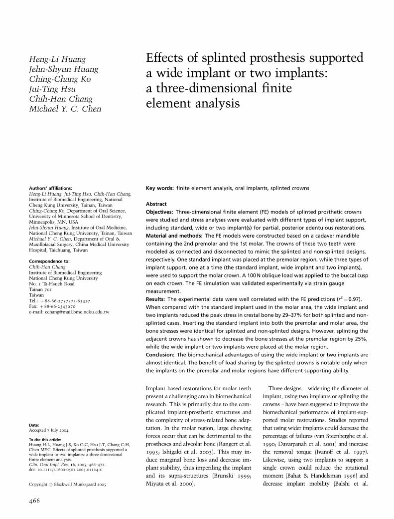
Fig. 1. Illustrations of (a) Model Spl-S, the splinted crown were supported by one standard implant at the 1st
molar site and one standard implant at the 2nd premolar site. The oblique loads (100 N each) were applied on
the buccal functional cusps. (b) Model Spl-T, the splinted crown were supported by two standard implants at
the 1st molar site and one standard implant at the 2nd premolar site. (c) Model nSpl-W, the non-splinted crowns
were supported by one wide implant at the 1st molar site and one standard implant 2nd at the premolar site. Spl,
splinted crown; nSpl, non-splinted crown; S, standard implant; T, two implants; W, wide implant.
Huang et al . Stress analysis of implant & prostheses designs
467 | Clin. Oral Impl. Res. 16, 2005 / 466–472
To examine the convergence level, the
p-value of the p-element was set to be
bounded between 2 (initial value) and 8
until the convergence was accomplished.
The p-level tolerance for convergence cri-
teria was set as the global strain energy
change less than 5%.
Material properties of the cortical and the
cancellous bone of the six models were
applied as transversely isotropic and lin-
early elastic (O’Mahony et al. 2001) while
the materials of implant and prosthetic
crown were assumed to be isotropic, and
linearly elastic (Sertgoz & Guvener 1996;
Ciftci & Canay 2000). All materials’ prop-
erties are listed in Table 2. The bite forces
were applied to buccal cusps of two pros-
thetic crowns with 451 bucccal inclination
(Fig 1). The load magnitudes were 100 N
for each site. The boundary condition
was constrained at the bottom surface of
the mandibular bone in all directions. The
bone–implant interface was identified as
bonded in all models to simulate osseoin-
tegration.
The mesh model Spl-S was further used
for the experimental validation. In this
model, the material properties, loading
and boundary conditions were re-assigned
based on the experimental setup described
in the next paragraph. The principal strains
of this validation model were compared
with those measured from the experi-
ments. The surface nodes on the lingual
mandible near the implant, corresponding
to the measured areas of experimental
strain gauges, were selected to calcu-
late the mean principal strains for the
comparison.
ESGA
Using the acrylic resin (Tempron, GC,
Kasugai, Japan), a posterior mandibular
sample was duplicated from the same man-
dibular cadaver used in the FE modeling.
The splinted second premolar and first
molar crown (crown type of Model Spl-S)
was also replicated with another acrylic
resin (Luxatemp, DMG, Hamburg, Ger-
many). The material properties of these
two resins were measured by the uni-axial
compressive test on cube specimens that
were plastered with bi-axial strain gauges.
The Young’s modulus was calculated from
the slope of the stress-strain curve within
the elastic region. The Poisson’s ratios
were obtained from the quotient of the
transverse (et) and axial (ea) strains, that
is, n¼ et/ea. These material properties are
listed in Table 3 and were used in the
validation FE model mentioned above.
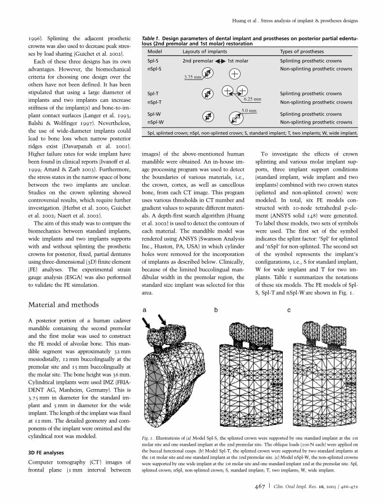
Two stainless steel cylinders (diameter
3.75 mm, length 12 mm), mimicking the
implants, were embedded in the mandibu-
lar model with the splinted crown. Two
single-axis strain gauges (KFG-1-120-C1-
11L1M2R, KYOWA, Tokyo, Japan) were
cemented on the lingual side of mandibular
model near the implant with cyano-acry-
late cement (CC-33A, KYOWA), oriented
toward the directions of the minimal prin-
cipal strain obtained from the validation FE
model (Fig. 2).
In order to evaluate various loading ef-
fects, a clamping jig was designed with an
adjustable screw-system so that the verti-
cal load could be transferred into an oblique
load on the implant/mandible construct.
On the premolar crown and the molar
crown, a force was applied either at the
center fossa with vertical direction or at the
buccal cusp with 451 buccal inclination;
hence, in total, there were four loading
conditions (Table 4). For each of these
four loading cases, two force magnitudes,
100 and 200 N, were applied. The strain
values were recorded through the data ac-
quisition system (instruNet Hardware,
GW instruments, Inc., Somerville, MA,
USA). Each measurement was repeated
three times.
Results
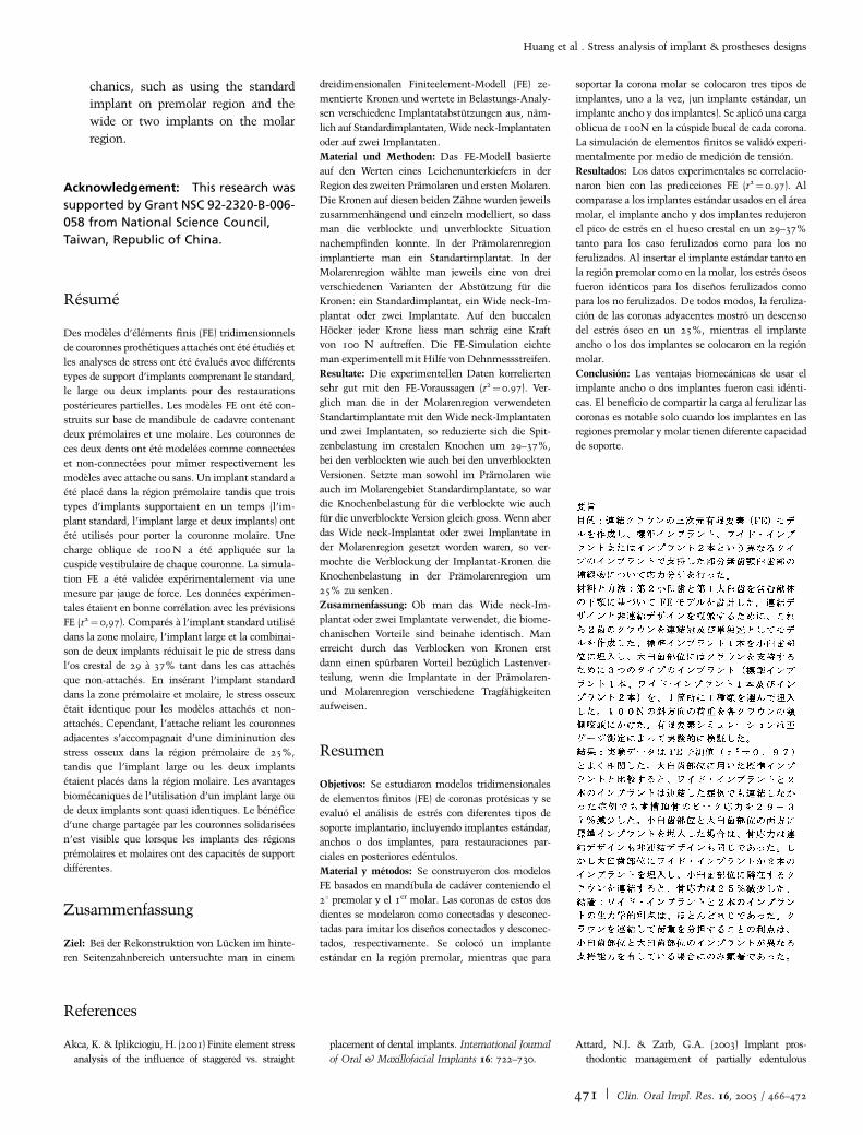
Table 4 shows the minimum (compressive)
principal strains in the experimental model
and the validation FE model under the four
loading conditions. In general, the experi-
Table 2. Material properties of the finite element models
Material Young’s modulusE (MPa)
Poisson’sratio n
Shear modulusG (MPa)
Cortical bone Ex¼ 12,600 nxy¼ 0.3 Gxy¼ 4850nyz¼ 0.253
Ey¼ 12,600 nxz¼ 0.253 Gyz¼ 5700nyx¼ 0.3
Ez¼ 19,400 nzy¼ 0.39 Gxz¼ 5700nzx¼ 0.39
Cancellous bone Ex¼ 1148 nxy¼ 0.055 Gxy¼ 68nyz¼ 0.01
Ey¼ 210 nxz¼ 0.322 Gyz¼ 68nyx¼ 0.01
Ez¼ 1148 nzy¼ 0.055 Gxz¼ 434nzx¼ 0.322
Titanium 110,000 0.35Porcelain 70,000 0.19
The vectors of x, y and z indicate the buccolingual, infero-superior and mesiodistal direction,
respectively.
Table 3. Young’s Modulus and Poisson’s ratio of each material of the experimental modelwas assigned to the validation finite element model
Material Young’s modulus E (MPa) Poisson’s ratio n
Resin (temporon) 2979 0.4Resin (Luxa temp) 6880 0.4Steel (ASTM-A242) 200,000 0.3
Fig. 2. The strain gauges were attached on the lin-
gual side of the experimental mandibular mold. The
resistors of each strain gauge were set along the
direction of minimum principal strains obtained
from the finite element model. Arrows indicate
the four loading points (dimples) located on the
central fossa and functional cusps.
Huang et al . Stress analysis of implant & prostheses designs
468 | Clin. Oral Impl. Res. 16, 2005 / 466–472
mental strains were higher than the simu-
lated strains and the differences were 10%
to 50%. However, comparing within all
loadings, the experimental and simulated
results did show a consistent relationship.
This indicated a high correlation between
the experimental and the FE approaches
(r2¼0.97). Moreover, the experimental-
ly measured compressive strains were
doubled when the loading increased from
100 to 200 N, which indicated the linear
status of this model.
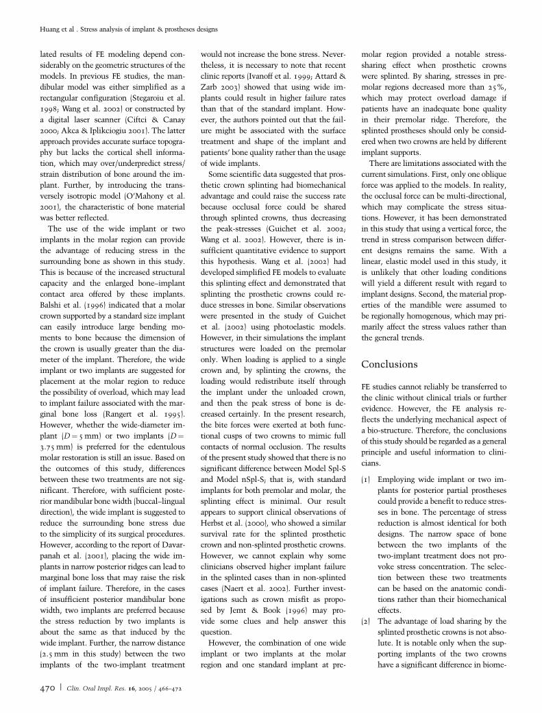
Figure 3 shows the von Mises stress
distributions on the cortical bone of the six
FE models. High stresses were located at the
alveolar crest around the implants, which
matched the clinical observations of crestal
bone loss (Rangert et al. 1995). In addition,
no stress was concentrated at the space
between the two implants of two-implant
models (Models Spl-T and nSpl-T).
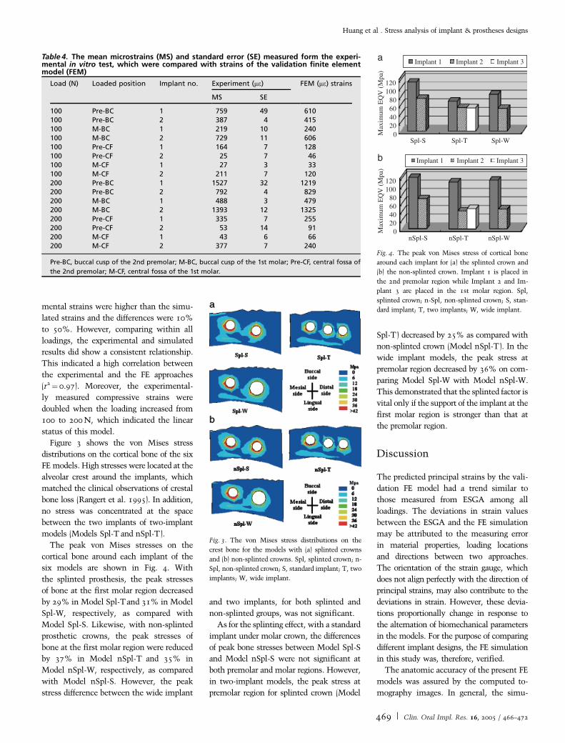
The peak von Mises stresses on the
cortical bone around each implant of the
six models are shown in Fig. 4. With
the splinted prosthesis, the peak stresses
of bone at the first molar region decreased
by 29% in Model Spl-Tand 31% in Model
Spl-W, respectively, as compared with
Model Spl-S. Likewise, with non-splinted
prosthetic crowns, the peak stresses of
bone at the first molar region were reduced
by 37% in Model nSpl-T and 35% in
Model nSpl-W, respectively, as compared
with Model nSpl-S. However, the peak
stress difference between the wide implant
and two implants, for both splinted and
non-splinted groups, was not significant.
As for the splinting effect, with a standard
implant under molar crown, the differences
of peak bone stresses between Model Spl-S
and Model nSpl-S were not significant at
both premolar and molar regions. However,
in two-implant models, the peak stress at
premolar region for splinted crown (Model
Spl-T) decreased by 25% as compared with
non-splinted crown (Model nSpl-T). In the
wide implant models, the peak stress at
premolar region decreased by 36% on com-
paring Model Spl-W with Model nSpl-W.
This demonstrated that the splinted factor is
vital only if the support of the implant at the
first molar region is stronger than that at
the premolar region.
Discussion
The predicted principal strains by the vali-
dation FE model had a trend similar to
those measured from ESGA among all
loadings. The deviations in strain values
between the ESGA and the FE simulation
may be attributed to the measuring error
in material properties, loading locations
and directions between two approaches.
The orientation of the strain gauge, which
does not align perfectly with the direction of
principal strains, may also contribute to the
deviations in strain. However, these devia-
tions proportionally change in response to
the alternation of biomechanical parameters
in the models. For the purpose of comparing
different implant designs, the FE simulation
in this study was, therefore, verified.
The anatomic accuracy of the present FE
models was assured by the computed to-
mography images. In general, the simu-
Table 4. The mean microstrains (MS) and standard error (SE) measured form the experi-mental in vitro test, which were compared with strains of the validation finite elementmodel (FEM)
Load (N) Loaded position Implant no. Experiment (me) FEM (me) strains
MS SE
100 Pre-BC 1 759 49 610100 Pre-BC 2 387 4 415100 M-BC 1 219 10 240100 M-BC 2 729 11 606100 Pre-CF 1 164 7 128100 Pre-CF 2 25 7 46100 M-CF 1 27 3 33100 M-CF 2 211 7 120200 Pre-BC 1 1527 32 1219200 Pre-BC 2 792 4 829200 M-BC 1 488 3 479200 M-BC 2 1393 12 1325200 Pre-CF 1 335 7 255200 Pre-CF 2 53 14 91200 M-CF 1 43 6 66200 M-CF 2 377 7 240
Pre-BC, buccal cusp of the 2nd premolar; M-BC, buccal cusp of the 1st molar; Pre-CF, central fossa of
the 2nd premolar; M-CF, central fossa of the 1st molar.
Fig. 3. The von Mises stress distributions on the
crest bone for the models with (a) splinted crowns
and (b) non-splinted crowns. Spl, splinted crown; n-
Spl, non-splinted crown; S, standard implant; T, two
implants; W, wide implant.
120100
80604020
0Spl-S Spl-T Spl-W
120100
80604020
0nSpl-S nSpl-T nSpl-W
Implant 1 Implant 2 Implant 3
Implant 1 Implant 2 Implant 3
Max
imum
EQ
V (
Mpa
)M
axim
um E
QV
(M
pa)
a
b
Fig. 4. The peak von Mises stress of cortical bone
around each implant for (a) the splinted crown and
(b) the non-splinted crown. Implant 1 is placed in
the 2nd premolar region while Implant 2 and Im-
plant 3 are placed in the 1st molar region. Spl,
splinted crown; n-Spl, non-splinted crown; S, stan-
dard implant; T, two implants; W, wide implant.
Huang et al . Stress analysis of implant & prostheses designs
469 | Clin. Oral Impl. Res. 16, 2005 / 466–472
lated results of FE modeling depend con-
siderably on the geometric structures of the
models. In previous FE studies, the man-
dibular model was either simplified as a
rectangular configuration (Stegaroiu et al.
1998; Wang et al. 2002) or constructed by
a digital laser scanner (Ciftci & Canay
2000; Akca & Iplikciogiu 2001). The latter
approach provides accurate surface topogra-
phy but lacks the cortical shell informa-
tion, which may over/underpredict stress/
strain distribution of bone around the im-
plant. Further, by introducing the trans-
versely isotropic model (O’Mahony et al.
2001), the characteristic of bone material
was better reflected.
The use of the wide implant or two
implants in the molar region can provide
the advantage of reducing stress in the
surrounding bone as shown in this study.
This is because of the increased structural
capacity and the enlarged bone–implant
contact area offered by these implants.
Balshi et al. (1996) indicated that a molar
crown supported by a standard size implant
can easily introduce large bending mo-
ments to bone because the dimension of
the crown is usually greater than the dia-
meter of the implant. Therefore, the wide
implant or two implants are suggested for
placement at the molar region to reduce
the possibility of overload, which may lead
to implant failure associated with the mar-
ginal bone loss (Rangert et al. 1995).
However, whether the wide-diameter im-
plant (D¼5 mm) or two implants (D¼3.75 mm) is preferred for the edentulous
molar restoration is still an issue. Based on
the outcomes of this study, differences
between these two treatments are not sig-
nificant. Therefore, with sufficient poste-
rior mandibular bone width (buccal–lingual
direction), the wide implant is suggested to
reduce the surrounding bone stress due
to the simplicity of its surgical procedures.
However, according to the report of Davar-
panah et al. (2001), placing the wide im-
plants in narrow posterior ridges can lead to
marginal bone loss that may raise the risk
of implant failure. Therefore, in the cases
of insufficient posterior mandibular bone
width, two implants are preferred because
the stress reduction by two implants is
about the same as that induced by the
wide implant. Further, the narrow distance
(2.5 mm in this study) between the two
implants of the two-implant treatment
would not increase the bone stress. Never-
theless, it is necessary to note that recent
clinic reports (Ivanoff et al. 1999; Attard &
Zarb 2003) showed that using wide im-
plants could result in higher failure rates
than that of the standard implant. How-
ever, the authors pointed out that the fail-
ure might be associated with the surface
treatment and shape of the implant and
patients’ bone quality rather than the usage
of wide implants.
Some scientific data suggested that pros-
thetic crown splinting had biomechanical
advantage and could raise the success rate
because occlusal force could be shared
through splinted crowns, thus decreasing
the peak-stresses (Guichet et al. 2002;
Wang et al. 2002). However, there is in-
sufficient quantitative evidence to support
this hypothesis. Wang et al. (2002) had
developed simplified FE models to evaluate
this splinting effect and demonstrated that
splinting the prosthetic crowns could re-
duce stresses in bone. Similar observations
were presented in the study of Guichet
et al. (2002) using photoelastic models.
However, in their simulations the implant
structures were loaded on the premolar
only. When loading is applied to a single
crown and, by splinting the crowns, the
loading would redistribute itself through
the implant under the unloaded crown,
and then the peak stress of bone is de-
creased certainly. In the present research,
the bite forces were exerted at both func-
tional cusps of two crowns to mimic full
contacts of normal occlusion. The results
of the present study showed that there is no
significant difference between Model Spl-S
and Model nSpl-S; that is, with standard
implants for both premolar and molar, the
splinting effect is minimal. Our result
appears to support clinical observations of
Herbst et al. (2000), who showed a similar
survival rate for the splinted prosthetic
crown and non-splinted prosthetic crowns.
However, we cannot explain why some
clinicians observed higher implant failure
in the splinted cases than in non-splinted
cases (Naert et al. 2002). Further invest-
igations such as crown misfit as propo-
sed by Jemt & Book (1996) may pro-
vide some clues and help answer this
question.
However, the combination of one wide
implant or two implants at the molar
region and one standard implant at pre-
molar region provided a notable stress-
sharing effect when prosthetic crowns
were splinted. By sharing, stresses in pre-
molar regions decreased more than 25%,
which may protect overload damage if
patients have an inadequate bone quality
in their premolar ridge. Therefore, the
splinted prostheses should only be consid-
ered when two crowns are held by different
implant supports.
There are limitations associated with the
current simulations. First, only one oblique
force was applied to the models. In reality,
the occlusal force can be multi-directional,
which may complicate the stress situa-
tions. However, it has been demonstrated
in this study that using a vertical force, the
trend in stress comparison between differ-
ent designs remains the same. With a
linear, elastic model used in this study, it
is unlikely that other loading conditions
will yield a different result with regard to
implant designs. Second, the material prop-
erties of the mandible were assumed to
be regionally homogenous, which may pri-
marily affect the stress values rather than
the general trends.
Conclusions
FE studies cannot reliably be transferred to
the clinic without clinical trials or further
evidence. However, the FE analysis re-
flects the underlying mechanical aspect of
a bio-structure. Therefore, the conclusions
of this study should be regarded as a general
principle and useful information to clini-
cians.
(1) Employing wide implant or two im-
plants for posterior partial prostheses
could provide a benefit to reduce stres-
ses in bone. The percentage of stress
reduction is almost identical for both
designs. The narrow space of bone
between the two implants of the
two-implant treatment does not pro-
voke stress concentration. The selec-
tion between these two treatments
can be based on the anatomic condi-
tions rather than their biomechanical
effects.
(2) The advantage of load sharing by the
splinted prosthetic crowns is not abso-
lute. It is notable only when the sup-
porting implants of the two crowns
have a significant difference in biome-
Huang et al . Stress analysis of implant & prostheses designs
470 | Clin. Oral Impl. Res. 16, 2005 / 466–472
chanics, such as using the standard
implant on premolar region and the
wide or two implants on the molar
region.
Acknowledgement: This research was
supported by Grant NSC 92-2320-B-006-
058 from National Science Council,
Taiwan, Republic of China.
Resume
Des modeles d’elements finis (FE) tridimensionnels
de couronnes prothetiques attaches ont ete etudies et
les analyses de stress ont ete evalues avec differents
types de support d’implants comprenant le standard,
le large ou deux implants pour des restaurations
posterieures partielles. Les modeles FE ont ete con-
struits sur base de mandibule de cadavre contenant
deux premolaires et une molaire. Les couronnes de
ces deux dents ont ete modelees comme connectees
et non-connectees pour mimer respectivement les
modeles avec attache ou sans. Un implant standard a
ete place dans la region premolaire tandis que trois
types d’implants supportaient en un temps (l’im-
plant standard, l’implant large et deux implants) ont
ete utilises pour porter la couronne molaire. Une
charge oblique de 100 N a ete appliquee sur la
cuspide vestibulaire de chaque couronne. La simula-
tion FE a ete validee experimentalement via une
mesure par jauge de force. Les donnees experimen-
tales etaient en bonne correlation avec les previsions
FE (r2¼ 0,97). Compares a l’implant standard utilise
dans la zone molaire, l’implant large et la combinai-
son de deux implants reduisait le pic de stress dans
l’os crestal de 29 a 37% tant dans les cas attaches
que non-attaches. En inserant l’implant standard
dans la zone premolaire et molaire, le stress osseux
etait identique pour les modeles attaches et non-
attaches. Cependant, l’attache reliant les couronnes
adjacentes s’accompagnait d’une dimininution des
stress osseux dans la region premolaire de 25%,
tandis que l’implant large ou les deux implants
etaient places dans la region molaire. Les avantages
biomecaniques de l’utilisation d’un implant large ou
de deux implants sont quasi identiques. Le benefice
d’une charge partagee par les couronnes solidarisees
n’est visible que lorsque les implants des regions
premolaires et molaires ont des capacites de support
differentes.
Zusammenfassung
Ziel: Bei der Rekonstruktion von Lucken im hinte-
ren Seitenzahnbereich untersuchte man in einem
dreidimensionalen Finiteelement-Modell (FE) ze-
mentierte Kronen und wertete in Belastungs-Analy-
sen verschiedene Implantatabstutzungen aus, nam-
lich auf Standardimplantaten, Wide neck-Implantaten
oder auf zwei Implantaten.
Material und Methoden: Das FE-Modell basierte
auf den Werten eines Leichenunterkiefers in der
Region des zweiten Pramolaren und ersten Molaren.
Die Kronen auf diesen beiden Zahne wurden jeweils
zusammenhangend und einzeln modelliert, so dass
man die verblockte und unverblockte Situation
nachempfinden konnte. In der Pramolarenregion
implantierte man ein Standartimplantat. In der
Molarenregion wahlte man jeweils eine von drei
verschiedenen Varianten der Abstutzung fur die
Kronen: ein Standardimplantat, ein Wide neck-Im-
plantat oder zwei Implantate. Auf den buccalen
Hocker jeder Krone liess man schrag eine Kraft
von 100 N auftreffen. Die FE-Simulation eichte
man experimentell mit Hilfe von Dehnmessstreifen.
Resultate: Die experimentellen Daten korrelierten
sehr gut mit den FE-Voraussagen (r2¼0.97). Ver-
glich man die in der Molarenregion verwendeten
Standartimplantate mit den Wide neck-Implantaten
und zwei Implantaten, so reduzierte sich die Spit-
zenbelastung im crestalen Knochen um 29–37%,
bei den verblockten wie auch bei den unverblockten
Versionen. Setzte man sowohl im Pramolaren wie
auch im Molarengebiet Standardimplantate, so war
die Knochenbelastung fur die verblockte wie auch
fur die unverblockte Version gleich gross. Wenn aber
das Wide neck-Implantat oder zwei Implantate in
der Molarenregion gesetzt worden waren, so ver-
mochte die Verblockung der Implantat-Kronen die
Knochenbelastung in der Pramolarenregion um
25% zu senken.
Zusammenfassung: Ob man das Wide neck-Im-
plantat oder zwei Implantate verwendet, die biome-
chanischen Vorteile sind beinahe identisch. Man
erreicht durch das Verblocken von Kronen erst
dann einen spurbaren Vorteil bezuglich Lastenver-
teilung, wenn die Implantate in der Pramolaren-
und Molarenregion verschiedene Tragfahigkeiten
aufweisen.
Resumen
Objetivos: Se estudiaron modelos tridimensionales
de elementos finitos (FE) de coronas protesicas y se
evaluo el analisis de estres con diferentes tipos de
soporte implantario, incluyendo implantes estandar,
anchos o dos implantes, para restauraciones par-
ciales en posteriores edentulos.
Material y metodos: Se construyeron dos modelos
FE basados en mandıbula de cadaver conteniendo el
21 premolar y el 1er molar. Las coronas de estos dos
dientes se modelaron como conectadas y desconec-
tadas para imitar los disenos conectados y desconec-
tados, respectivamente. Se coloco un implante
estandar en la region premolar, mientras que para
soportar la corona molar se colocaron tres tipos de
implantes, uno a la vez, (un implante estandar, un
implante ancho y dos implantes). Se aplico una carga
oblicua de 100N en la cuspide bucal de cada corona.
La simulacion de elementos finitos se valido experi-
mentalmente por medio de medicion de tension.
Resultados: Los datos experimentales se correlacio-
naron bien con las predicciones FE (r2¼ 0.97). Al
comparase a los implantes estandar usados en el area
molar, el implante ancho y dos implantes redujeron
el pico de estres en el hueso crestal en un 29–37%
tanto para los caso ferulizados como para los no
ferulizados. Al insertar el implante estandar tanto en
la region premolar como en la molar, los estres oseos
fueron identicos para los disenos ferulizados como
para los no ferulizados. De todos modos, la feruliza-
cion de las coronas adyacentes mostro un descenso
del estres oseo en un 25%, mientras el implante
ancho o los dos implantes se colocaron en la region
molar.
Conclusion: Las ventajas biomecanicas de usar el
implante ancho o dos implantes fueron casi identi-
cas. El beneficio de compartir la carga al ferulizar las
coronas es notable solo cuando los implantes en las
regiones premolar y molar tienen diferente capacidad
de soporte.
References
Akca, K. & Iplikciogiu, H. (2001) Finite element stress
analysis of the influence of staggered vs. straight
placement of dental implants. International Journal
of Oral & Maxillofacial Implants 16: 722–730.
Attard, N.J. & Zarb, G.A. (2003) Implant pros-
thodontic management of partially edentulous
Huang et al . Stress analysis of implant & prostheses designs
471 | Clin. Oral Impl. Res. 16, 2005 / 466–472
patients missing posterior teeth: the Toronto experi-
ence. Journal of Prosthetic Dentistry 89: 352–359.
Bahat, O. & Handelsman, M. (1996) Use of wide
implants and two implants in the posterior jaw: a
clinical report. International Journal of Oral &
Maxillofacial Implants 11: 379–386.
Balshi, T.J., Hernandez, R.E., Pryszlak, M.C &
Rangert, B. (1996) A comparative study of one
implant vs. two replacing a single molar. Interna-
tional Journal of Oral & Maxillofacial Implants
11: 372–378.
Balshi, T.J. & Wolfinger, G.J. (1997) Two-implant-
supported single molar replacement: interdental
space requirements and comparison to alternative
options. International Journal of Periodontics &
Restorative Dentistry 17: 427–435.
Brunski, J.B. (1999) In vivo bone response to bio-
mechanical loading at the bone/dental–implant
interface. Advances in Dental Research 13:
99–119.
Ciftci, Y. & Canay, S. (2000) The effect of veneering
materials on stress distribution in implant-sup-
ported fixed prosthetic restorations. International
Journal of Oral & Maxillofacial Implants 15:
571–582.
Davarpanah, M., Martines, H., Kebir, M., Etienne, D.
& Tecucianu, J.F. (2001) Wide-diameter implants:
new concepts. International Journal of Perio-
dontics & Restorative Dentistry 21: 149–159.
Guichet, D.L., Yoshinobu, D. & Caputo, A.A.
(2002) Effect of splinting and interproximal con-
tact tightness on load transfer by implant restora-
tions. Journal of Prosthetic Dentistry 87:
528–535.
Herbst, D., Nel, J.C., Driessen, C.H. & Becker, P.J.
(2000) Evaluation of impression accuracy for os-
seointegrated implant supported superstructure.
Journal of Prosthetic Dentistry 83: 555–561.
Huang, H.L., Chang, C.H., Ko, C.C., Lin, C.L &
Huang, J.S. (2002) Stress analyses of dental pros-
theses with various implant supported designs.
Journal of Medical & Biological Engineering 22:
s17–s24.
Ivanoff, C.-J., Grondahl, K., Sennerby, L., Berg-
strom, C. & Lekholm, U. (1999) Influence
of variations in implant diameters: a 3- to
5-year retrospective clinical report. International
Journal of Oral & Maxillofacial Implants 14:
173–180.
Ivanoff, C.-J., Sennerby, L., Johansson, C., Rangert,
B. & Lekholm, U. (1997) Influence of implant
diameters on the integration of screw implants.
An experimental study in rabbits. International
Journal of Oral and Maxillofacial Surgery 26:
141–148.
Ishigaki, S., Nakano, T., Yamada, S., Nakamura, T.
& Takashima, F. (2003) Biomechanical stress in
bone surrounding an implant under simulated
chewing. Clinical Oral Implants Research 14:
97–102.
Jemt, T. & Book, K. (1996) Prosthesis misfit and
marginal bone loss in edentulous implant pa-
tients. International Journal of Oral & Maxillo-
facial Implants 11: 620–625.
Langer, B., Langer, L., Herrmann, I. & Jorneus, L.
(1993) The wide fixture: a solution for special
bone and a rescue for the compromised implant.
part 1. International Journal of Oral & Maxillo-
facial Implants 8: 400–408.
Miyata, T., Kobayashi, Y. & Araki, H. (2000) The
influence of controlled occlusal overload on peri-
implant tissue. Part 3: a histologic study in
monkeys. International Journal of Oral & Max-
illofacial Implants 15: 425–431.
Naert, I., Koutsikakis, G., Duyck, J., Quirynen, M.,
Jacobs, R. & van Steenberghe, D. (2002) Biologic
outcome of implant-supported restoration in the
treatment of partial edentulism. Part 1. A long-
itudinal clinical evaluation. Clinical Oral Im-
plants Research 13: 381–389.
O’Mahony, A.M., Williams, J.L. & Spencer, P.
(2001) Anisotropic elasticity of cortical and con-
cellous bone in the posterior mandible increa-
ses peri-implant stress and strain under oblique
loading. Clinical Oral Implants Research 12:
648–657.
Rangert, B., Krogh, P.H.J. & Langer, B. (1995)
Bending Overload and implant fracture: a
retrospective clinical analysis. International Jour-
nal of Oral & Maxillofacial Implants 10:
326–334.
Sertgoz, A. & Guvener, S. (1996) Finite element
analysis of the effect of cantilever and implant
length on stress distribution in an implant-sup-
ported fixed prosthesis. Journal of Prosthetic Den-
tistry 76: 165–169.
Stegaroiu, R., Sato, T. & Kusakari, H. (1998)
Influence of restoration type on stress distribution
in bone around implants: a three-dimensional
finite element analysis. International Journal of
Oral & Maxillofacial Implants 13: 82–90.
van Steenberghe, D., Lekholm, U., Bolender, C.,
Folmer, T., Henry, P. & Herrmann, I. (1990)
Applicability of osseointegrated oral implants in
the rehabilitation of partial edentulism: a prospec-
tive multicenter study on 558 fixtures. Interna-
tional Journal of Oral & Maxillofacial Implants
5: 272–282.
Wang, T.M., Leu, L.J., Wang, J.S. & Lin, L.D. (2002)
Effects of prosthesis materials and prosthesis
splinting on peri-implant bone stress around im-
plants in poor-quality bone: a numeric analysis.
International Journal of Oral & Maxillofacial
Implants 17: 231–237.
Huang et al . Stress analysis of implant & prostheses designs
472 | Clin. Oral Impl. Res. 16, 2005 / 466–472

![INDEX [microdentsystem.com] · 2015-11-24 · INDEX PRESENTATION. INTRODUCTION MULTIPLE PROSTHESIS. REMOVABLE AND IMMEDIATE PROSTHESIS. SINGLE PROSTHESIS CEMENTED PROSTHESIS. Microdent](https://img.pdfslide.net/doc/110x75/5facd9ee77a5ed547a36b19c/index-2015-11-24-index-presentation-introduction-multiple-prosthesis-removable.jpg)