Embed Size (px)
Citation preview
European Association for the Development of Renewable Energies, Environment
and Power Quality (EA4EPQ)
International Conference on Renewable Energies and Power Quality (ICREPQ’12)
Santiago de Compostela (Spain), 28th to 30th March, 2012
Efficiency Analysis of Single-Phase Photovoltaic Transformer-less Inverters
M. Martino1, C. Citro2, K.Rouzbehi2, P. Rodriguez2
1 Department of Energy Technology at Aalborg University Pontoppidanstræde 101 · 9220 Aalborg e-mail: [email protected]
2 Electrical Department at University Politechnique of Catalunya
email: [email protected], [email protected], [email protected]
Abstract. This paper presents an efficiency analysis of five single-phase transformer-less inverters for photovoltaic applications (Full H-Bridge, Half H-Bridge, H5, HERIC and NPC inverters) implemented with different topologies of switches. Silicon (Si) and Silicon Carbide (SiC) diodes have been considered combined with two kinds of IGBTs. Simulation results have been obtained for each of the systems in different operating conditions by using PLECS software. Power losses and European Efficiency (EE) have been calculated for all the topologies by including the real characteristics of the switches in the thermal models provided by the software.
Keywords Transformer-less PV inverter, IGBTs, Silicon diodes, Silicon Carbide Diodes, European Efficiency. 1. Introduction
Renewable energy sources and mostly photovoltaic (PV) applications are nowadays experiencing a fast and continuous development. From the scientific point of view, the effort over the last years has gone into increasing the efficiency of PV cells and bringing down the manufacturing costs. Taken into account that the efficiency of the PV panels currently available on the market is only 15-20%, a crucial aspect in these kinds of applications is to design efficient power electronics systems to exploit the most of the produced energy. The main component of these systems is the PV inverter, representing the 25% of the whole system cost [1].
Inverters used in PV systems can be grouped into two main categories: the isolated and the non-isolated inverters. The former, in order to create a galvanic isolation between the input and the output include a transformer (mandatory in some countries) that limits the whole system performances in terms of efficiency, weight, size and cost. On the contrary, transformer-less inverters do not present any isolation and are characterized by little size, lower cost and higher efficiency (more than 2% higher). Nevertheless, the lack of transformers leads to leakage currents that can be harmful to the human body, as well as for the whole conversion system integrity. This can
be considered their main drawback [4]. The goal of this paper is to evaluate the efficiency of
different topologies of single-phase transformer-less PV inverters, implemented with different kinds of switches. Silicon (Si) and Silicon Carbide (SiC) diodes have been considered combined with two different IGBTs available on the market. Simulation results have been obtained for each of the systems in different operating conditions by using PLECS software.
A block diagram of the simulated systems is shown in Figure 1.
Figure 1. Block diagram of the simulated systems
The LC filter components considered for all the topologies have been designed using reference [3].
Power losses and European Efficiency (EE) have been calculated for all the topologies considering the real characteristics of the switches by including parameters of datasheets in the thermal models provided by the software.
Hereinafter, Section II introduces the concept of European Efficiency, while Section III describes the different tested inverter topologies. Section IV describes how the different simulations have been performed while Section V presents the obtained results. Conclusions are drawn in Section VI.
2. European Efficiency The efficiency of a power converter is defined by the
following equation:
(1)
https://doi.org/10.24084/repqj10.765 1569 RE&PQJ, Vol.1, No.10, April 2012
where is the DC input power. In the considered systems the losses are mainly due to the internal power dissipation of the switches (IGBTs and diodes in our case).
Since in the real applications, PV systems are installed in a wide range of solar sources, in order to take into account the different levels of efficiency at different levels of input power, a different factor is commonly used, the so-called European efficiency (EE) [9]. This parameter is a weighted conversion efficiency index and is defined as:
(2)
where is the conversion efficiency at of inverter input power. The typical EE of PV power converters is in the range 95-98%. 3. PV Inverter Topologies
This section presents a short description of the different inverter topologies tested in the simulations.
A. Full H-Bridge Inverter
The full H-bridge converter considered in this paper presents a DC decoupling scheme [7] which adds two extra switches and two extra diodes to common H-Bridge topology. IGBTs T5-T6 are switched at high frequency, while switches T1-T4 are switched with the grid frequency and in anti-parallel to T2, T3, depending on whether the reference voltage is in the positive or negative half period.
Figure 2. Full DC decoupled H-Bridge Inverter
B. Half H-Bridge Inverter
The Half H-bridge topology is formed by 2 IGBTs and a capacitive divider connected to the PV array (Fig. 3).
Figure3. Half H-Bridge Inverter
The connection of the grid neutral wire to the capacitive divider midpoint ensures an almost constant common
mode voltage, thus preventing leakage current through the parasitic capacitance of the PV module.
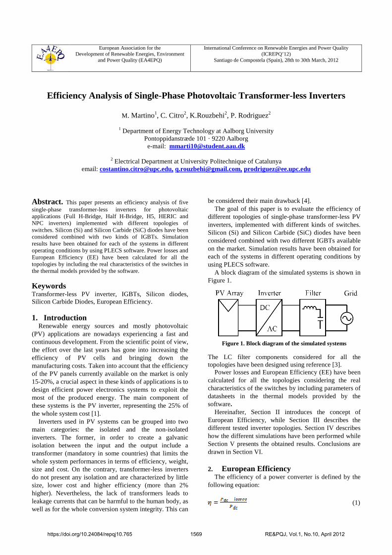
C. NPC Inverter
The operation of Neutral point clamp (NPC) topology (Fig.4) can be described as follow: during the positive half cycle, T2 remains ON, T1 commutates at switching frequency and T3 and T4 are OFF; in more detail, when T1 is ON the current flows through T1 and T2 toward the grid (current increasing), while when T1 is OFF, the current flows through D5 and T2 (current decreasing). During the negative half cycle, T3 remains ON, whereas T4 commutates at switching frequency and T1 and T2 are OFF; when T4 is ON current flows through T3 and T4 toward the grid (current increasing). Moreover, when T4 is OFF, the current flows through T3 and D6 (current decreasing) [8].
Figure 4. NPC Inverter
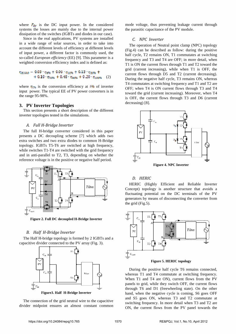
D. HERIC
HERIC (Highly Efficient and Reliable Inverter Concept) topology is another structure that avoids a fluctuating potential on the DC terminals of the PV generators by means of disconnecting the converter from the grid (Fig.5).
Figure 5. HERIC topology
During the positive half cycle T6 remains connected, whereas T1 and T4 commutate at switching frequency. When T1 and T4 are ON), current flows from the PV panels to grid, while they switch OFF, the current flows through T6 and D1 (freewheeling state). On the other hand, when the negative cycle is coming, S6 goes OFF and S5 goes ON, whereas T3 and T2 commutate at switching frequency. In more detail when T3 and T2 are ON, the current flows from the PV panel towards the
https://doi.org/10.24084/repqj10.765 1570 RE&PQJ, Vol.1, No.10, April 2012
load, thus when T3 and T2 turn off, the current flows through T5 and D2 [8].
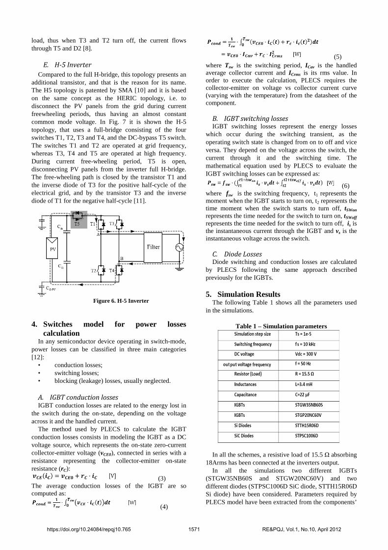
E. H-5 Inverter
Compared to the full H-bridge, this topology presents an additional transistor, and that is the reason for its name. The H5 topology is patented by SMA [10] and it is based on the same concept as the HERIC topology, i.e. to disconnect the PV panels from the grid during current freewheeling periods, thus having an almost constant common mode voltage. In Fig. 7 it is shown the H-5 topology, that uses a full-bridge consisting of the four switches T1, T2, T3 and T4, and the DC-bypass T5 switch. The switches T1 and T2 are operated at grid frequency, whereas T3, T4 and T5 are operated at high frequency. During current free-wheeling period, T5 is open, disconnecting PV panels from the inverter full H-bridge. The free-wheeling path is closed by the transistor T1 and the inverse diode of T3 for the positive half-cycle of the electrical grid, and by the transistor T3 and the inverse diode of T1 for the negative half-cycle [11].
Figure 6. H-5 Inverter
4. Switches model for power losses
calculation In any semiconductor device operating in switch-mode,
power losses can be classified in three main categories [12]:
• conduction losses; • switching losses; • blocking (leakage) losses, usually neglected. A. IGBT conduction losses IGBT conduction losses are related to the energy lost in
the switch during the on-state, depending on the voltage across it and the handled current.
The method used by PLECS to calculate the IGBT conduction losses consists in modeling the IGBT as a DC voltage source, which represents the on-state zero-current collector-emitter voltage (vCE0), connected in series with a resistance representing the collector-emitter on-state resistance (rC):
(3) The average conduction losses of the IGBT are so computed as:
(4)
(5) where Tsw is the switching period, ICav is the handled average collector current and ICrms is its rms value. In order to execute the calculation, PLECS requires the collector-emitter on voltage vs collector current curve (varying with the temperature) from the datasheet of the component.
B. IGBT switching losses IGBT switching losses represent the energy losses
which occur during the switching transient, as the operating switch state is changed from on to off and vice versa. They depend on the voltage across the switch, the current through it and the switching time. The mathematical equation used by PLECS to evaluate the IGBT switching losses can be expressed as:
(6) where fsw is the switching frequency, t1 represents the moment when the IGBT starts to turn on, t2 represents the time moment when the switch starts to turn off, tSWon represents the time needed for the switch to turn on, tSWoff
represents the time needed for the switch to turn off, is is the instantaneous current through the IGBT and vs is the instantaneous voltage across the switch.
C. Diode Losses Diode switching and conduction losses are calculated
by PLECS following the same approach described previously for the IGBTs.
5. Simulation Results The following Table 1 shows all the parameters used
in the simulations.
Table 1 – Simulation parameters
In all the schemes, a resistive load of 15.5 Ω absorbing 18Arms has been connected at the inverters output.
In all the simulations two different IGBTs (STGW35NB60S and STGW20NC60V) and two different diodes (STPSC1006D SiC diode, STTH15R06D Si diode) have been considered. Parameters required by PLECS model have been extracted from the components’
https://doi.org/10.24084/repqj10.765 1571 RE&PQJ, Vol.1, No.10, April 2012
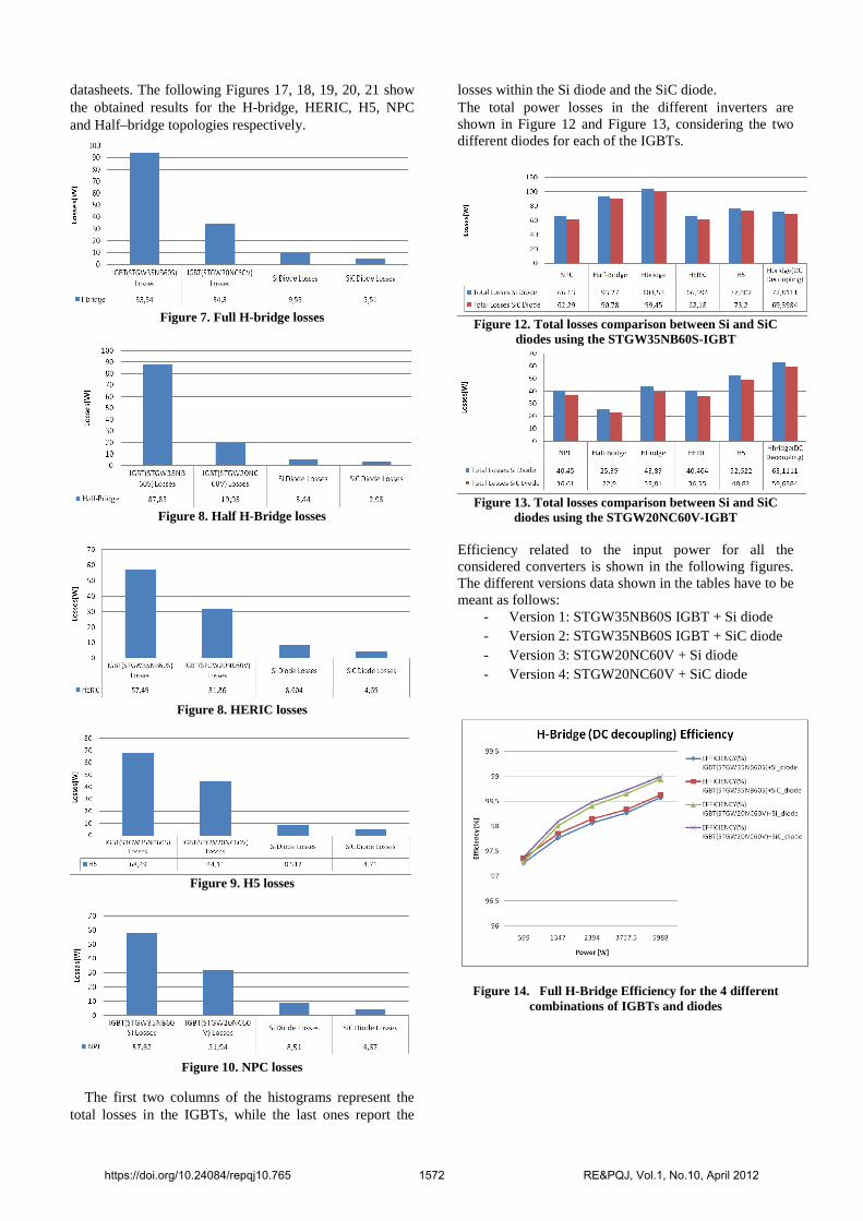
datasheets. The following Figures 17, 18, 19, 20, 21 show the obtained results for the H-bridge, HERIC, H5, NPC and Half–bridge topologies respectively.
Figure 7. Full H-bridge losses
Figure 8. Half H-Bridge losses
Figure 8. HERIC losses
Figure 9. H5 losses
Figure 10. NPC losses
The first two columns of the histograms represent the total losses in the IGBTs, while the last ones report the
losses within the Si diode and the SiC diode. The total power losses in the different inverters are shown in Figure 12 and Figure 13, considering the two different diodes for each of the IGBTs.
Figure 12. Total losses comparison between Si and SiC
diodes using the STGW35NB60S-IGBT
Figure 13. Total losses comparison between Si and SiC
diodes using the STGW20NC60V-IGBT Efficiency related to the input power for all the considered converters is shown in the following figures. The different versions data shown in the tables have to be meant as follows:
- Version 1: STGW35NB60S IGBT + Si diode - Version 2: STGW35NB60S IGBT + SiC diode - Version 3: STGW20NC60V + Si diode - Version 4: STGW20NC60V + SiC diode
Figure 14. Full H-Bridge Efficiency for the 4 different combinations of IGBTs and diodes
https://doi.org/10.24084/repqj10.765 1572 RE&PQJ, Vol.1, No.10, April 2012
Version 1 Version 2 Version 3 Version 4
98% 98,1% 98,3% 98,4%
Table 2. Full H-Bridge European Efficiency for the 4 different combinations of IGBTs and diodes
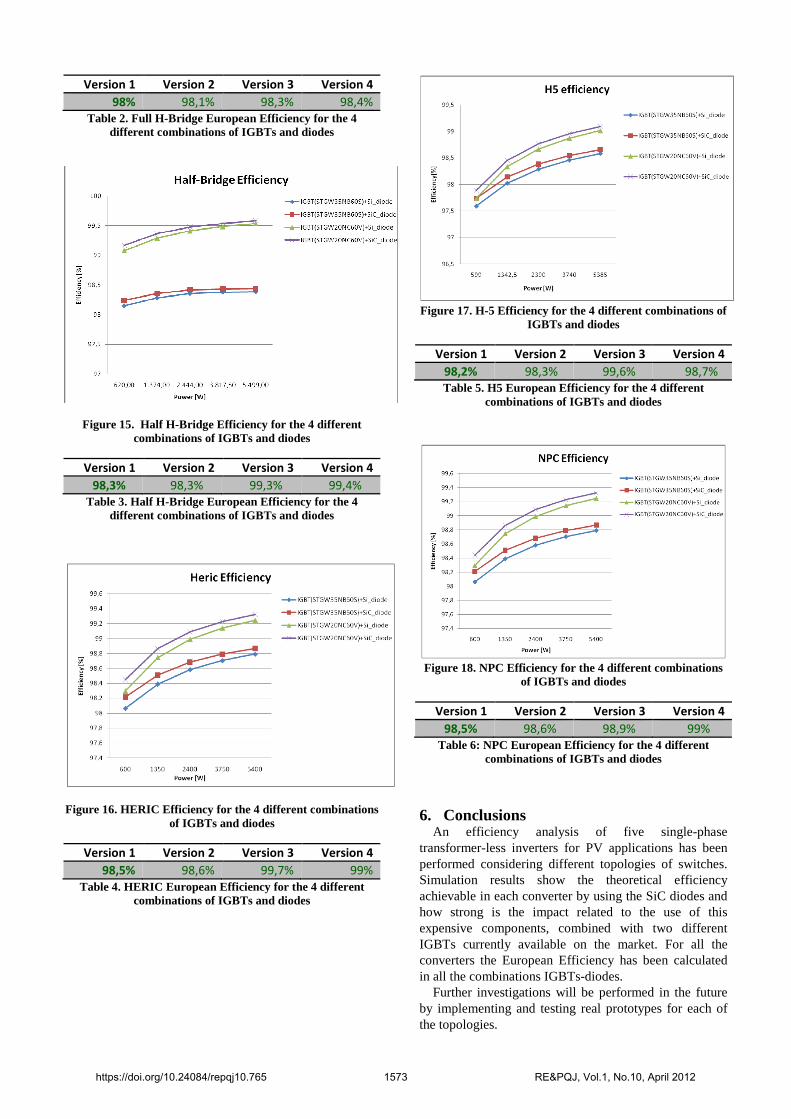
Figure 15. Half H-Bridge Efficiency for the 4 different combinations of IGBTs and diodes
Version 1 Version 2 Version 3 Version 4
98,3% 98,3% 99,3% 99,4%
Table 3. Half H-Bridge European Efficiency for the 4 different combinations of IGBTs and diodes
Figure 16. HERIC Efficiency for the 4 different combinations of IGBTs and diodes
Version 1 Version 2 Version 3 Version 4
98,5% 98,6% 99,7% 99%
Table 4. HERIC European Efficiency for the 4 different combinations of IGBTs and diodes
Figure 17. H-5 Efficiency for the 4 different combinations of
IGBTs and diodes
Version 1 Version 2 Version 3 Version 4
98,2% 98,3% 99,6% 98,7%
Table 5. H5 European Efficiency for the 4 different combinations of IGBTs and diodes
Figure 18. NPC Efficiency for the 4 different combinations
of IGBTs and diodes
Version 1 Version 2 Version 3 Version 4
98,5% 98,6% 98,9% 99%
Table 6: NPC European Efficiency for the 4 different combinations of IGBTs and diodes
6. Conclusions An efficiency analysis of five single-phase
transformer-less inverters for PV applications has been performed considering different topologies of switches. Simulation results show the theoretical efficiency achievable in each converter by using the SiC diodes and how strong is the impact related to the use of this expensive components, combined with two different IGBTs currently available on the market. For all the converters the European Efficiency has been calculated in all the combinations IGBTs-diodes.
Further investigations will be performed in the future by implementing and testing real prototypes for each of the topologies.
https://doi.org/10.24084/repqj10.765 1573 RE&PQJ, Vol.1, No.10, April 2012
7. Acknowledgement This work was supported in part by the projects ENE 2008-06841-C02/ALT and TRA2009-0103 of Spanish Ministry of Science and Innovation. 8. References
[1] Kerekes Tamas; "Analysis and Modelling of
Transformerless Photovoltaic Inverter Systems", 2009 PhD thesis, Aalborg University.
[2] Rashid Muhammad H., "Power Electronics", 2003. [3] Dahono, P.A.; Purwadi, A.; Qamaruzzaman; "An LC
filter design method for single-phase PWM inverters", Power Electronics and Drive Systems, 1995., Proceedings of 1995 International Conference on , vol., no., pp.571-576 vol.2, 21-24 Feb 1995.
[4] Araujo, S.V.; Zacharias, P.; Mallwitz, R.; "Highly Efficient Single-Phase Transformerless Inverters for Grid-Connected Photovoltaic Systems", Industrial Electronics, IEEE Transactions on , vol.57, no.9, pp.3118-3128, Sept. 2010.
[5] Kerekes, T.; Teodorescu, R.; Rodríguez, P.; Vázquez, G.; Aldabas, E.; "A New High-Efficiency Single-Phase Transformerless PV Inverter Topology", Industrial Electronics, IEEE Transactions on , vol.58, no.1, pp.184-191, Jan. 2011.
[6] Gonzalez, Roberto; Lopez, Jesus; Sanchis, Pablo; Gubia, Eugenio; Ursua, Alfredo; Marroyo, Luis; "High-Efficiency Transformerless Single-phase Photovoltaic Inverter", Power Electronics and Motion Control Conference, 2006. EPE-PEMC 2006. 12th International , vol., no., pp.1895-1900, Aug. 30 2006-Sept. 1 2006.
[7] Gonzalez, R.; Lopez, J.; Sanchis, P.; Marroyo, L.; "Transformerless Inverter for Single-Phase Photovoltaic Systems", Power Electronics, IEEE Transactions on , vol.22, no.2, pp.693-697, March 2007.
[8] Vazquez, G.; Kerekes, T.; Rolan, A.; Aguilar, D.; Luna, A.; Azevedo, G.; "Losses and CMV evaluation in transformerless grid-connected PV topologies", Industrial Electronics, 2009. ISIE 2009. IEEE International Symposium on , vol., no., pp.544-548, 5-8 July 2009.
[9] Valentini, M.; Raducu, A.; Sera, D.; Teodorescu, R.; "PV inverter test setup for European efficiency, static and dynamic MPPT efficiency evaluation", Optimization of Electrical and Electronic Equipment, 2008. OPTIM 2008. 11th International Conference on , vol., no., pp.433-438, 22-24 May 2008.
[10] Victor M, Greizer F, Bremicker S, Hübler U.
Patent: “Method of converting a DC voltage of a DC
source, in particular of a photovoltaic DC source, in an AC voltage” [EP 1 626 494]. 25-6-2004.
[11] Iván Patrao, Emilio Figueres, Fran González-Espín, Gabriel Garcerá “Transformerless topologies for grid-connected single-phase photovoltaic inverters”, Elsevier Renewable and Sustainable Energy Reviews 15 (2011) 3423– 3431.
[12] Graovac Dusan and Marco Purschel, "IGBT Power Losses Calculation Using the Datasheet Parameters", vol. Application Note v1.1, 2009.
https://doi.org/10.24084/repqj10.765 1574 RE&PQJ, Vol.1, No.10, April 2012