Embed Size (px)
Citation preview
Efficient Document Image SegmentationRepresentation by Approximating Minimum-Link
Polygons
George Retsinas1,2, Georgios Louloudis1, Nikolaos Stamatopoulos1 and Basilis Gatos1
1 Computational Intelligence Laboratory, Institute of Informatics and Telecommunications
National Center for Scientific Research ”Demokritos”
GR-15310 Athens, Greece
{georgeretsi,louloud,nstam,bgat}@iit.demokritos.gr
2 School of Electrical and Computer Engineering
National Technical University of Athens
GR-15773 Athens, Greece
Abstract—The result of a document image segmentation task,e.g. text line or word segmentation, is usually a labeled imagewith each label corresponding to a different segmented region.For many applications, the segmented regions need to be storedand represented in an efficient way, using simple geometricshapes. A challenging task is to restrict all pixels correspondingto a specific label inside a polygon with a minimum numberof vertices. Such a polygon promotes the description simplicityand the storage efficiency, while providing a much more user-friendly representation that can be edited easily. The proposedmethod is a cost-effective approximation of the minimum-edgespolygon problem, computing a contour enclosing only pixels of acertain label and using a greedy algorithm in order to reduce thecontour into a minimum-link polygon that retains the separabilityproperty between the labeled set of pixels.
Keywords—Document Image Segmentation Representation,Groundtruth Representation, Minimum-Link Polygon Approx-imation
I. INTRODUCTION
A basic preprocessing step in the document analysis and
recognition pipeline is image segmentation to specific ele-
ments, such as regions, text lines, words or even characters.
The majority of the approaches for document image segmen-
tation that have been proposed in the literature, result in a
labeled image that represents different segmented regions, ac-
cording to the segmentation task (e.g. region, text line or word
segmentation) [1],[2]. Labeled images, though descriptive and
easy to construct as a segmentation task output, are difficult
to represent and need many storage resources.
In order to address the problem of defining a simple and
efficient representation, it is imperative to restrict all labeled
elements inside simple geometric shapes, such as polygons
defined by their vertices. This approach provides a simple
conceptual representation for each segmented region and re-
sults to a very compact and storage efficient representation
of the document image segmentation results. Furthermore,
this representation is useful for user interaction tasks, such
as quickly evaluating or even editing a segmentation result
by simply moving some of the boundary polygon vertices.
These editing actions are supported by ground-truthing and
transcription applications, such as the Aletheia tool [3] and
Transkribus [4], and can be further simplified by using less
points to represent the segmented regions.
A convenient representation is to use the surrounding rectan-
gular box (bounding box) of every distinct segmented region,
which corresponds to storing only four points, the vertices
of the bounding box. Another convenient representation is to
use the convex hull of every distinct segmented region, which
results in storing a larger set of points (the vertices of the
convex hull polygon) with the benefit of a “tighter” represen-
tation of the segmented region. These approaches are usually
inadequate due to possible overlaps between the boxes/convex
hulls and consequently this results to poor representation of
the elements that cannot be separated anymore. Overlapping
convex hulls of segmented regions is a common case in
handwritten documents (see Fig. 1) and thus it is important
to address the problem of correctly representing segmented
regions in an efficient way.
(a)
(b)Fig. 1. Two text lines with overlapping (a) bounding boxes (b) convex hulls.
In [5], isothetic polygons are proposed for document seg-
mentation representation. These are polygons that have only
2016 12th IAPR Workshop on Document Analysis Systems
978-1-5090-1792-8/16 $31.00 © 2016 IEEE
DOI 10.1109/DAS.2016.59
293
horizontal and vertical edges or equivalently correspond to
the union of a set of rectangles. An isothetic polygon is
constructed by iteratively adding and subtracting simple rect-
angular blocks in order to enclose only the pixels of a specific
label, while trying to keep the edges as few as possible.
Starting from the bounding box of the selected label, at each
step, the minimum-edge rectangles that enclose pixels from
another label are subtracted and consequently the minimum-
edge rectangles that enclose the pixels which belong to the
selected label and are not in the current polygon are added.
However, the use of isothetic polygons approach has some
obvious drawbacks, even though it may work sufficiently well
for several segmentation scenarios. Specifically, when the seg-
mented regions are very close to each other, isothetic polygons
will converge after many iterations and the final representation
will consists of a large number of points due to the restriction
of horizontal/vertical edges resulting in a procedure similar to
contour-following. It can be easily observed that the time and
storage complexity of this approach is heavily dependent on
the spatial arrangement of neighboring regions.
In this paper, a novel approach for the polygonal represen-
tation problem is proposed, trying to address the aforemen-
tioned drawbacks of isothetic polygons. The main goal of our
approach is to loosen the restriction of vertical and horizontal
edges and allow any polygon as a representation, thus giving
a more generic and robust description that further decreases
the number of storage points. Our approach is based on a two-
step scheme. First, we extract a contour that encloses only the
pixels of a selected label using Distance Transform [6]. At the
next step, a greedy algorithm is used in order to construct the
final polygonal representation by retaining as few points as
possible from the contour.
The remainder of the paper is organized as follows. In
Section II, we discuss about the formalization and the com-
plexity of the problem. In Section III, the proposed method
is described in detail, while some applications and examples
are presented in Section IV. Finally, conclusions are drawn in
Section V.
II. PROBLEM DESCRIPTION
For the rest of the paper we define two different sets of
pixels. The first set, denoted as Point Set A or Interior Point
Set, consists of the pixels corresponding to a selected label,
while the second set, denoted as Point Set B or Exterior Point
Set, consists of any other labeled pixel. The background with
no label (or labeled as zero) is the “free” space, where a
polygon can expand without a problem.
For the trivial case of non-overlapping convex hulls or
bounding boxes between every pair of the segmented regions,
a satisfying solution would be the convex hull or the bounding
box accordingly.
Our goal is to build upon the simplicity of the convex hull
representation by finding the smallest (non-convex) polygonal
envelop containing only the points that belong to a specific
label, as it is stated below:
Minimum Separating Polygon: Given a Set of InteriorPoints A = {a1, a2, ..., aN} and a Set of Exterior PointsB = {b1, b2, ..., bK}, find a Polygon P with the minimumPerimeter such that every ai is inside P and every bi is outsideP or, equivalently, find the minimum-perimeter Polygon P thatseparates the two Sets.
A special case of the above problem occurs when none
of the points in Set B lies inside the convex hull of Set
A. In this case, the Minimum Separating Polygon is in fact
the Convex Hull of the Set A, which can be computed in
O(nlogn) (Graham Scan [7]). However, for the general case,
the problem is NP-hard, as shown in [8].
Due to the fact that the initial problem belongs to the
NP-hard complexity class, we choose to change the min-
imum perimeter optimization goal and replace it with the
optimization goal of minimizing the number of the polygon
edges (or equivalently the number of vertices), denoted as
minimum-link goal in the literature, which is more efficient
in terms of storage requirements. Furthermore, we add a
new constraint to the bounding area of the resulting polygon
because unconstrained minimum-link optimization may result
to flawed representations that are far off the initial goal
of minimum-perimeter polygons (see Fig. 2). Therefore we
constrain the minimum-link polygon to lie into the area defined
by a bounding (convex) polygon C. In practice, an expanded
bounding box is used as the bounding polygon C, which
promotes a more descriptive representation as it is depicted
in Fig. 3. The above problem is formulated as follows:
Minimum-Link Representation Polygon: Given a Set ofInterior Points A = {a1, a2, ..., aN}, a Set of Exterior PointsB = {b1, b2, ..., bK} and a Bounding Polygon C, find aPolygon P inside C with the minimum number of edges/linkssuch that every ai is inside P and every bi is outside P.
The above problem is also a separating problem between
two sets (the boundary points of the bounding polygon C
can be also considered points of the exterior point set) with
the goal of optimizing the edges of the separating polygon.
However, this problem still belongs to NP-hard complexity
class [9].
As it will be described in detail in the upcoming section,
we propose an efficient approximation, with linear complexity
in terms of the image size, to the later problem in order to
represent a segmented region using a polygon to separate the
points of the label of interest from any other labeled points.
The proposed approach assumes that such a polygon exists.
III. PROPOSED METHODOLOGY
The proposed methodology emphasizes on finding an ap-
proximation of the minimum edge (restricted) polygon at a
low computational cost, using a two-step scheme: a) estimate
a contour enclosing only the label of interest b) efficiently
reduce the contour to a valid polygon with as few edges
as possible. Segmented region representation has not a strict
requirement over the number of polygon vertices and it will
be beneficial if the whole procedure was fast enough as part
of an application or an interaction tool. Therefore, we prefer
294
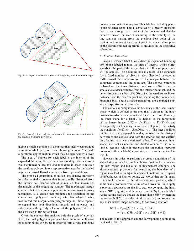
Fig. 2. Example of a non-descriptive enclosing polygon with minimum edges.
Fig. 3. Example of an enclosing polygon with minimum edges restricted inthe (dashed) bounding polygon C.
taking a rough estimation of a contour that ideally can produce
a minimum-link polygon over choosing a more “rational”
algorithmic approximation which may be significantly slower.
The area of interest for each label is the interior of the
expanded bounding box of the corresponding pixel set. As it
was mentioned before, this choice is done in order to restrain
the resulting polygon into a representative area for the labeled
region and avoid flawed non-descriptive representations.
The proposed approximation utilizes the distance transform
in order to find a contour that is maximally distanced from
the interior and exterior sets of points, i.e. that maximizes
the margin of the separating contour. The maximized margin
contour, that is a common practice in separating/optimizing
techniques, is a choice that promotes the reduction of the
contour to a polygonal boundary with few edges. Having
maximized this margin, each polygon edge has more “space”
to expand into both directions, inwards and outwards, and
subsequently the greedy selection of the polygon vertices in
the next step is further assisted.
Given the contour that encloses only the pixels of a certain
label, the final polygon is produced by a minimum collection
of contour points as vertices in order to form a valid polygonal
boundary without including any other label or excluding pixels
of the selected label. This is achieved by a greedy algorithm
that passes through each point of the contour and decides
either to discard or keep it according to the validity of the
line segment starting from the previous kept point of the
contour and ending at the current point. A detailed description
of the aforementioned algorithm is provided in the respective
subsection.
A. Contour Extraction
Given a selected label l, we extract an expanded bounding
box of the labeled region, the area of interest, which corre-
sponds to the part of the image that the following procedures
will be applied. The bounding box is chosen to be expanded
(by a fixed number of pixels at each direction) in order to
further assist the maximization of the margin between the
computed contour and the point sets. The contour extraction
is based on the inner distance transform IntDistl, i.e. the
smallest euclidean distance from the interior point set, and the
outer distance transform ExtDistl, i.e. the smallest euclidean
distance from the exterior point set, including the boundary of
bounding box. These distance transforms are computed only
at the respective area of interest.
The contour is computed as the boundary of the label’s inner
shape, which is defined as the area that is closer to the inner
distance transform than the outer distance transform. Formally,
the inner shape for a label l is defined as the foreground
of the binary image BWl = IntDistl < ExtDistl, and
consequently its boundary is consisted of pixels that satisfy
the condition |IntDistl−ExtDistl| < 1. The later condition
implies that the proposed boundary maximizes the distance
between of the contour and both the interior and the exterior
set of points, as it was mentioned before. The computed inner
shape is in fact an non-uniform dilated version of the initial
labeled regions, while it preserves the separation (between
points of different labels) constraint, as it can be depicted in
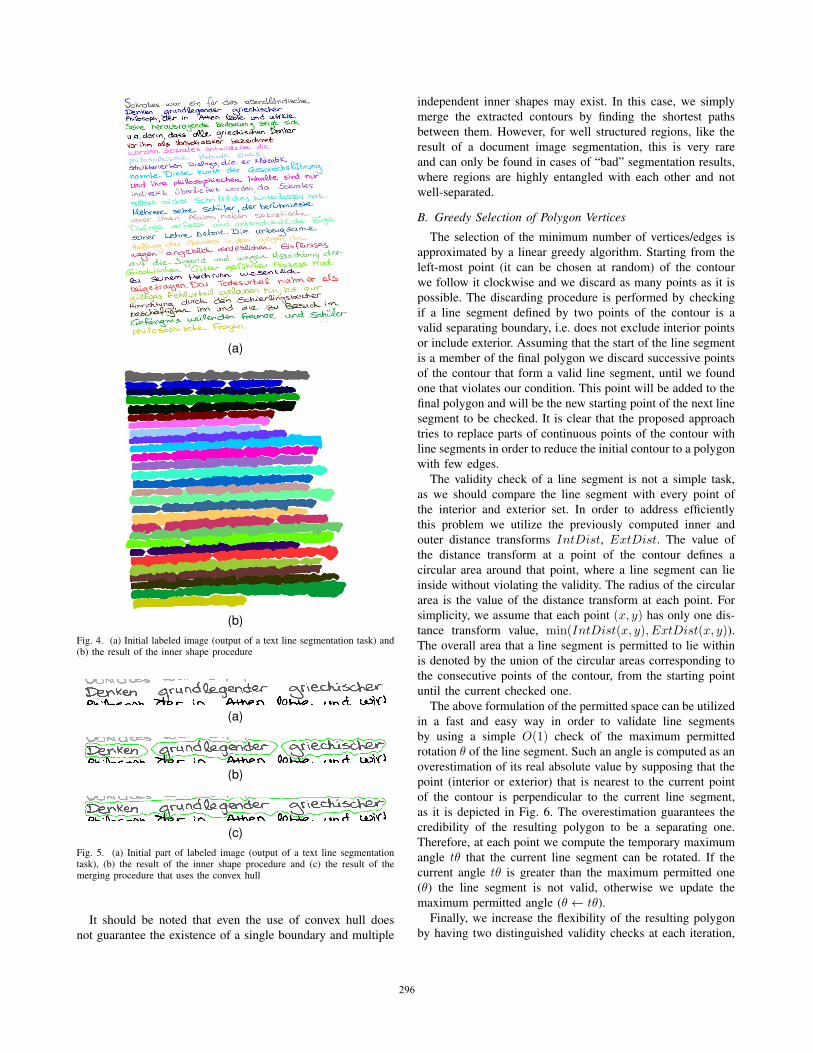
Fig. 4.
However, in order to perform the greedy algorithm of the
second step we need a simple cohesive contour for represent-
ing each region and not a set of independent contours. The
aforementioned procedure for extracting the boundary of a
region may lead to multiple independent contours due to sparse
neighborhoods of interior points, e.g. words that are far apart.
A simple solution to the aforementioned problem, which
additionally promotes results similar to convex hull, is to apply
a two-pass approach. At the first pass we compute the inner
shape BWl (Fig. 4b) and the convex hull CHl for each label.
At the second pass we update the inner shape BW ′l by merging
the convex hull CHl and the initial shape BWl and subtracting
any other label’s shape according to following relation:
BW ′l = ∩i �=l[(CHl ∪BWl) \BWi]
= {x ∈ CHl ∪BWl : x /∈ BWi, i �= l}The results of this approach and the corresponding contour are
depicted in Fig. 5.
295
(a)
(b)Fig. 4. (a) Initial labeled image (output of a text line segmentation task) and(b) the result of the inner shape procedure
(a)
(b)
(c)Fig. 5. (a) Initial part of labeled image (output of a text line segmentationtask), (b) the result of the inner shape procedure and (c) the result of themerging procedure that uses the convex hull
It should be noted that even the use of convex hull does
not guarantee the existence of a single boundary and multiple
independent inner shapes may exist. In this case, we simply
merge the extracted contours by finding the shortest paths
between them. However, for well structured regions, like the
result of a document image segmentation, this is very rare
and can only be found in cases of “bad” segmentation results,
where regions are highly entangled with each other and not
well-separated.
B. Greedy Selection of Polygon Vertices
The selection of the minimum number of vertices/edges is
approximated by a linear greedy algorithm. Starting from the
left-most point (it can be chosen at random) of the contour
we follow it clockwise and we discard as many points as it is
possible. The discarding procedure is performed by checking
if a line segment defined by two points of the contour is a
valid separating boundary, i.e. does not exclude interior points
or include exterior. Assuming that the start of the line segment
is a member of the final polygon we discard successive points
of the contour that form a valid line segment, until we found
one that violates our condition. This point will be added to the
final polygon and will be the new starting point of the next line
segment to be checked. It is clear that the proposed approach
tries to replace parts of continuous points of the contour with
line segments in order to reduce the initial contour to a polygon
with few edges.
The validity check of a line segment is not a simple task,
as we should compare the line segment with every point of
the interior and exterior set. In order to address efficiently
this problem we utilize the previously computed inner and
outer distance transforms IntDist, ExtDist. The value of
the distance transform at a point of the contour defines a
circular area around that point, where a line segment can lie
inside without violating the validity. The radius of the circular
area is the value of the distance transform at each point. For
simplicity, we assume that each point (x, y) has only one dis-
tance transform value, min(IntDist(x, y), ExtDist(x, y)).The overall area that a line segment is permitted to lie within
is denoted by the union of the circular areas corresponding to
the consecutive points of the contour, from the starting point
until the current checked one.
The above formulation of the permitted space can be utilized
in a fast and easy way in order to validate line segments
by using a simple O(1) check of the maximum permitted
rotation θ of the line segment. Such an angle is computed as an
overestimation of its real absolute value by supposing that the
point (interior or exterior) that is nearest to the current point
of the contour is perpendicular to the current line segment,
as it is depicted in Fig. 6. The overestimation guarantees the
credibility of the resulting polygon to be a separating one.
Therefore, at each point we compute the temporary maximum
angle tθ that the current line segment can be rotated. If the
current angle tθ is greater than the maximum permitted one
(θ) the line segment is not valid, otherwise we update the
maximum permitted angle (θ ← tθ).
Finally, we increase the flexibility of the resulting polygon
by having two distinguished validity checks at each iteration,
296
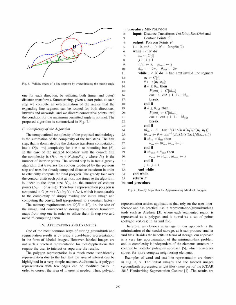
Fig. 6. Validity check of a line segment by overestimating the margin angle
one for each direction, by utilizing both (inner and outer)
distance transforms. Summarizing, given a start point, at each
step we compute an overestimation of the angles that the
expanding line segment can be rotated for both directions,
inwards and outwards, and we discard consecutive points until
the condition for the maximum permitted angle is not met. The
proposed algorithm is summarized in Fig. 7.
C. Complexity of the Algorithm
The computational complexity of the proposed methodology
is the summation of the complexity of the two steps. The first
step, that is dominated by the distance transform computation,
has a O(n · m) complexity for a n × m bounding box [6].
In the case of the merged boundary with the convex hull
the complexity is O(n · m + NAlogNA) , where NA is the
number of interior points. The second step is in fact a greedy
algorithm that traverses the contour produced by the previous
step and uses the already computed distance transform in order
to efficiently compute the final polygon. The greedy tour over
the contour visits each point at most two times so the algorithm
is linear to the input size NC , i.e. the number of contour
points (NC = O(n·m)). Therefore a representation polygon is
computed in O(n·m+NAlogNA+NC), which is comparable
to the complexity of simply reading the initial image and
computing the convex hull (proportional to a constant factor).
The memory requirements are O(N ×M), i.e. the size of
the image, and correspond to storing the distance transform
maps from step one in order to utilize them in step two and
avoid re-computing them.
IV. APPLICATIONS AND EXAMPLES
One of the most common ways of storing groundtruth and
segmentation results is by using a pixel-based representation,
in the form of labeled images. However, labeled images are
not such a practical representation for tools/applications that
require the user to interact or supervise the results.
The polygon representation is a much more user-friendly
representation due to the fact that the area of interest can be
highlighted in a very simple manner. Additionally, a polygon
representation with few edges can be modified easily in
order to correct the area of interest if needed. Thus, polygon
1: procedure MINPOLYGON
2: input: Distance Transforms IntDist, ExtDist and
3: Contour Points C4: output: Polygon Points P5: i← 0, cnt← 0, N ← length(C)6: while i < N do7: as ← C[i]8: j ← i+ 19: idin ← j, idout ← j
10: θin ← −2π, θout ← 2π11: while j < N do � find next invalid line segment
12: at ← C[j]13: θ ← � (at,as);14: if θ ≤ θin then15: P [cnt]← C[idin]16: cntv ← cnt+ 1, i← idin17: break18: end if19: if θ ≥ θout then20: P [cnt]← C[idout]21: cnt← cnt+ 1. i← idout22: break23: end if24: tθin ← θ − tan−1(IntDist(at)/d(as,at))25: tθout ← θ + tan−1(ExtDist(at)/d(as,at))26: if tθin > θin then27: θin ← tθin, idin ← j28: end if29: if tθout < θout then30: θout ← tθout, idout ← j31: end if32: j ← j + 1;
33: end while34: end while35: return P36: end procedure
Fig. 7. Greedy Algorithm for Approximating Min-Link Polygon
representation assists applications that rely on the user inter-
ference and has practical use in representation/groundtruthing
tools such as Aletheia [3], where each segmented region is
represented as a polygon and is stored as a set of points
(polygon vertices) in an xml file.
Therefore, an obvious advantage of our approach is the
minimization of the needed storage, as it can produce smaller
xml files. Besides the benefits in terms of storage, our approach
is a very fast approximation of the minimum-link problem
and its complexity is independent of the elements structure in
contrast to isothetic polygons approach [5], which converges
slower for more complex neighboring elements.
Examples of word and text line representation are shown
in Fig. 8, 9. The initial images and the labeled images
(groundtruth represented as .dat files) were part of the ICDAR
2013 Handwriting Segmentation Contest [1]. The results are
297
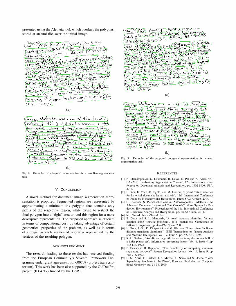
presented using the Aletheia tool, which overlays the polygons,
stored at an xml file, over the initial image.
(a)
(b)Fig. 8. Examples of polygonal representation for a text line segmentationtask
V. CONCLUSION
A novel method for document image segmentation repre-
sentation is proposed. Segmented regions are represented by
approximating a minimum-link polygon that contains only
pixels of the respective region, while trying to restrict the
final polygon into a “tight” area around this region for a more
descriptive representation. The proposed approach is efficient
in terms of computational cost, by taking advantage of certain
geometrical properties of the problem, as well as in terms
of storage, as each segmented region is represented by the
vertices of the resulting polygon.
ACKNOWLEDGMENT
The research leading to these results has received funding
from the European Community’s Seventh Framework Pro-
gramme under grant agreement no. 600707 (project tranScrip-
torium). This work has been also supported by the OldDocPro
project (ID 4717) funded by the GSRT.
(a)
(b)Fig. 9. Examples of the proposed polygonal representation for a wordsegmentation task
REFERENCES
[1] N. Stamatopoulos, G. Louloudis, B. Gatos, U. Pal and A. Alaei, “IC-DAR2013 Handwriting Segmentation Contest”, 12th International Con-ference on Document Analysis and Recognition, pp. 1402-1406, USA,2013.
[2] H. Wei, K. Chen, R. Ingold, and M. Liwicki, “Hybrid feature selectionfor historical document layout analysis”, 14th International Conferenceon Frontiers in Handwriting Recognition, pages 8792, Greece, 2014.
[3] C. Clausner, S. Pletschacher and A. Antonacopoulos, “Aletheia - AnAdvanced Document Layout and Text Ground-Truthing System for Pro-duction Environments”, Proceedings of the 11th International Conferenceon Document Analysis and Recognition, pp. 48-52, China, 2011.
[4] http://transkribus.eu/Transkribus[5] B. Gatos and S. L. Mantzaris, “A novel recursive algorithm for area
location using isothetic polygons”, 15th International Conference onPattern Recognition, pp. 496-499, Spain, 2000.
[6] H. Breu, J. Gil, D. Kirkpatrick and M. Werman, “Linear time Euclideandistance transform algorithms”, IEEE Transactions on Pattern Analysisand Machine Intelligence, Vol. 17, Issue 5, pp. 529-533, 1995.
[7] R. L. Graham, “An efficient algorith for determining the convex hull ofa finite planar set”, Information processing letters, Vol. 1, Issue 4, pp.132-133, 1972.
[8] P. Eades and D. Rappaport, “The complexity of computing minimumseparating polygons”, Pattern Recognition Letters, Vol. 14, Issue 9, pp.715-718, 1993.
[9] E. M. Arkin, F. Hurtado, J. S. Mitchel, C. Seara and S. Skiena, “SomeSeparability Problems in the Plane”, European Workshop on Computa-tional Geometry, pp. 51-54, 2000.
298