Embed Size (px)
Citation preview
Efficient multiscale modelling of path dependent problems
XIV International Conference on Computational Plasticity. Fundamentals and ApplicationsCOMPLAS XIV
E. Onate, D.R.J. Owen, D. Peric & M. Chiumenti (Eds)
EFFICIENT MULTI-SCALE MODELLING OF PATHDEPENDENT PROBLEMS – COMPLAS 2017
NINA ZUPAN∗, JOZE KORELC†
∗ Faculty of Civil and Geodetic EngineeringUniversity of Ljubljana
Jamova cesta 2, 1000 Ljubljana, Sloveniae-mail: [email protected], web page: http://www3.fgg.uni-lj.si
† Faculty of Civil and Geodetic EngineeringUniversity of Ljubljana
Jamova cesta 2, 1000 Ljubljana, Sloveniae-mail: [email protected], web page: http://www3.fgg.uni-lj.si
Key words: Multi-scale, MIEL, sensitivity analysis, path dependent
Abstract. With growing capabilities of computers use of multi-scale methods for detailedanalysis of response with respect to material and geometric nonlinearities is becomingmore relevant. In this paper focus is on MIEL (mesh-in-element) multi-scale method andits implementation with AceGen and AceFEM based on analytical sensitivity analysis.Such implementation enables efficient multi-scale modelling, consistency and quadraticconvergence also for two-level path following methods for the solution of path dependentproblems.
1 INTRODUCTION
Implementation of multi-scale methods is possible in various ways. Here, the numericalscheme for implementation of MIEL multi-scale method based on sensitivity analysis ispresented. Implementation is done with the Mathematica packages AceGen and AceFEM[1]. Programs enable analytical sensitivity analysis of first and second order [2], that canbe used for efficient implementation of multi-scale finite element methods, eg. FE2 orMIEL.
2 AUTOMATIC DIFFERENTIATION BASED (ADB) NOTATION
AceGen is advanced automatic code generator, where automatic differentiation tech-nique, automatic code optimization and generation are combined with computer algebrasystemMathematica[3]. Size of code is reduced through control of expression swell[4]. TheAceFEM package is a general finite element environment designed to solve multi-physicsand multi-field problems.
1
926
N. Zupan, J. Korelc
Automation of primal and sensitivity analysis is done with AceGen. The automaticdifferentiation technique (AD) can be used for the evaluation of the exact derivatives ofany arbitrary complex function via chain rule and represents an alternative solution tothe numerical differentiation and symbolic differentiation. The result of AD procedure is
called ”computational derivative” and is written as δf(a)
δa. The AD operator δf(a)
δarepresents
partial derivative of a function f(a) with respect to variables a. If, for example, alternativeor additional dependencies for a set of intermediate variables b have to be considered fordifferentiation, then the AD exception is indicated by the following formalism
δf(a,b)
δa
∣∣∣∣∣DbDa
=M
, (1)
which indicates that during the AD procedure, the total derivatives of variables b withrespect to variables a are set to be equal to matrix M. The automatic differentiationexceptions are the basis for the ADB formulation of computational problem. The ADBnotation can be directly translated to the AceGen input and is part of numerically efficientcode automation. Details of the method and of the corresponding software AceGen canbe found in [4], [2] and [5].
The automation of multi-scale analysis requires the automation of primal and sensi-tivity analysis. In primal analysis the response of the system is evaluated, whereas insensitivity analysis the derivatives of the response, e.g. displacements, strains, stressesor work, with respect to arbitrary design parameter φi are sought. The primal problemis solved by the standard Newton-Raphson iterative procedure (see e.g. [2]). For theautomation of the multi-scale methods the sensitivity analysis with respect to prescribedessential boundary conditions is needed.
3 MULTI-SCALE METHODS
Multi-scale methods are nowadays widespread in computational mechanics [6, 7, 8].They usually originate from the demand to model heterogeneous materials, like fiberreinforced composites, particle reinforced adhesives, concrete and even metal. FE2 is astandard two-level finite element homogenization approach [9], that is appropriate for theproblems where scales are separated far enough and are only weakly coupled. FE2 methodis already implemented in AceFEM using sensitivity analysis, for details reader is referredto [10, 11]. In some cases for example when difference between two scales is finite, or whenin the region of high gradients, the FE2 multi-scale approach fails, thus we need to usesome sort of domain decomposition method. One possibility is the mesh-in-element orMIEL scheme described e.g. by Markovic and Ibrahimbegovic in [12].
3.1 MIEL method
MIEL method is variant of domain decomposition methods. Here its implementationbased on sensitivity analysis is presented. The finite element models at different scalescommunicate between each other through degrees of freedom of the finite element at
2
927
N. Zupan, J. Korelc
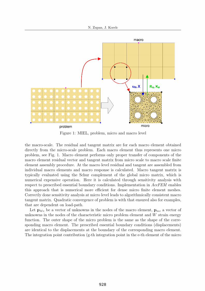
Figure 1: MIEL, problem, micro and macro level
the macro-scale. The residual and tangent matrix are for each macro element obtaineddirectly from the micro-scale problem. Each macro element thus represents one microproblem, see Fig. 1. Macro element performs only proper transfer of components of themacro element residual vector and tangent matrix from micro scale to macro scale finiteelement assembly procedure. At the macro level residual and tangent are assembled fromindividual macro elements and macro response is calculated. Macro tangent matrix istypically evaluated using the Schur complement of the global micro matrix, which isnumerical expensive operation. Here it is calculated through sensitivity analysis withrespect to prescribed essential boundary conditions. Implementation in AceFEM enablesthis approach that is numerical more efficient for dense micro finite element meshes.Correctly done sensitivity analysis at micro level leads to algorithmically consistent macrotangent matrix. Quadratic convergence of problem is with that ensured also for examples,that are dependent on load-path.
Let pMe be a vector of unknowns in the nodes of the macro element, pme a vector ofunknowns in the nodes of the characteristic micro problem element and W strain energyfunction. The outer shape of the micro problem is the same as the shape of the corre-sponding macro element. The prescribed essential boundary conditions (displacements)are identical to the displacements at the boundary of the corresponding macro element.The integration point contribution (g-th integration point in the e-th element of the micro
3
928
N. Zupan, J. Korelc
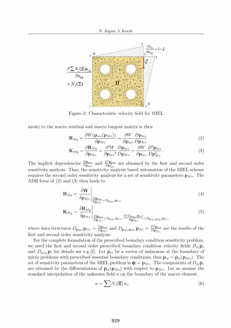
Figure 2: Characteristic velocity field for MIEL
mesh) to the macro residual and macro tangent matrix is then
RMg =∂W (pme(pMe))
∂pMe
=∂W
∂pme
Dpme
DpMe
(2)
KMg =∂RMg
∂pMe
=∂2W
∂pme2
Dpme
DpMe
+∂W
∂pme
D2pme
Dp2Me
. (3)
The implicit dependencies Dpme
DpM eand D2pme
Dp2M e
are obtained by the first and second order
sensitivity analysis. Thus, the sensitivity analysis based automation of the MIEL schemerequires the second order sensitivity analysis for a set of sensitivity parameters pMe. TheADB form of (2) and (3) then leads to
RMg =δW
δpMe
∣∣∣∣∣Dpme
DpM e=DpM e
pme
(4)
KMg =δRMg
δpMe
∣∣∣∣∣Dpme
DpM e=DpM e
pme,D(DpM e
pm)
DpM e=DpM epM e
pme
(5)
where data structures DpM epme =
Dpme
DpM eand DpM epM e
pme =D2pme
Dp2M e
are the results of the
first and second order sensitivity analysis.For the complete formulation of the prescribed boundary condition sensitivity problem,
we need the first and second order prescribed boundary condition velocity fields Dφipe
and Dφiφjpe for details see e.g.[2]. Let pm be a vector of unknowns at the boundary of
micro problems with prescribed essential boundary conditions, thus pm = pm(pMe). Theset of sensitivity parameters of the MIEL problem is φ = pMe. The components of Dφi
pe
are obtained by the differentiation of pm(pMe) with respect to pMe. Let us assume thestandard interpolation of the unknown field u on the boundary of the macro element
u =∑
Ni(Ξ) ui, (6)
4
929
N. Zupan, J. Korelc
where Ni(Ξ) are the shape functions and ui the nodal unknowns and∂u∂ui
= Ni(Ξ). Thus,the components of the first order boundary condition velocity field Dφi
pe are the valuesof the macro element shape functions at the position of the boundary nodes of the micromesh, see Fig. 2. For boundary condition in form of linear combination (6), the secondorder velocity field is zero Dφiφj
pe = 0.
4 EFFICIENCY IMPROVEMENT
Numerical efficiency of multi-scale methods can be improved in different ways. Firstimprovement was done at individual macro problem, with replacing calculation of Schurcomplement with sensitivity analysis based calculation of macro tangent matrix. Fordensely meshed micro-structure calculation of the Schur complement inflicts high memoryallocation and is time consuming, which is not the case for the sensitivity analysis basedimplementation. In case of MIEL method this is due to the fact that the number ofsensitivity parameters remains the same, regardless of the density of the micro mesh,whereas the size of the Schur complement grows with the number of the nodes on theboundary of the micro problem.
Further optimisation can be done with use of unified sensitivity based approach tomulti-scale modelling, that is enabled by automatic-differentiation-based (ADB) formula-tion for an arbitrary nonlinear, time dependent coupled problem (e.g. general finite strainplasticity). Different multi-scale methods FE2, MIEL and also single scale schemes canbe used together in one model. With that optimal domain discretization is possible. Forexample, MIEL that is numerically most demanding can be used only where it is needed,other ways FE2 or single-scale method can be used.
In AceFEM solving of nonlinear problems is done implicitly with a Newton-Raphsontype iterative solution procedure. Since we have two scales, we have in general a pathfollowing procedure at both scales, resulting in two-level path following procedure. Tra-ditionally, each step at macro level is followed by only one step at micro level. Sensitivityanalysis based multi-scale analysis allows extension to more general case, where eachmacro step can be followed by an arbitrary number of micro substeps.
Implementation of the presented multi-scale computational approach in AceFEM isfully parallelized for multi-core processors. Micro problems are distributed on kernels byevaluating each individual micro problem always at the same kernel. With parallelizedcomputation, computational time for complex problems can be significantly reduced. Thesetup is also appropriate for the implementation on clusters.
5 NUMERICAL EXAMPLE
Multi-scale MIEL method was tested on Cook membrane benchmark problem, to verifyconsistency and efficiency of micro-macro coupling. The homogeneous micro structure ischosen intentionally for the benchmark purposes. Effect of macro mesh density and useof different finite elements were investigated. With AceGen, the codes of analytical firstand second order sensitivity analysis are generated automatically. Examples were calcu-lated with AceFEM, where whole MIEL scheme is implemented including communication
5
930
N. Zupan, J. Korelc
between macro and micro scale. Essential boundary condition of macro mesh are sentto micro problem and interpolated over the edge. Important is that essential boundarycondition velocity fields are set correctly.
5.1 Description of example
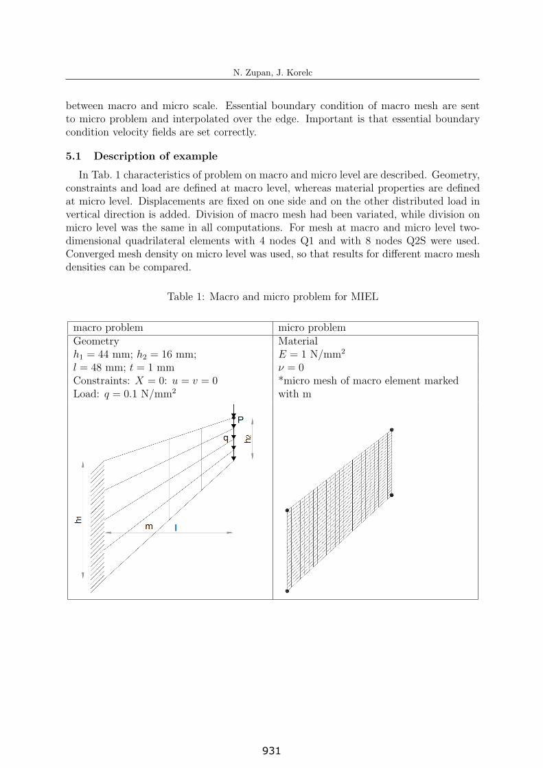
In Tab. 1 characteristics of problem on macro and micro level are described. Geometry,constraints and load are defined at macro level, whereas material properties are definedat micro level. Displacements are fixed on one side and on the other distributed load invertical direction is added. Division of macro mesh had been variated, while division onmicro level was the same in all computations. For mesh at macro and micro level two-dimensional quadrilateral elements with 4 nodes Q1 and with 8 nodes Q2S were used.Converged mesh density on micro level was used, so that results for different macro meshdensities can be compared.
Table 1: Macro and micro problem for MIEL
macro problem micro problemGeometry Materialh1 = 44 mm; h2 = 16 mm; E = 1 N/mm2
l = 48 mm; t = 1 mm ν = 0Constraints: X = 0: u = v = 0 *micro mesh of macro element markedLoad: q = 0.1 N/mm2 with m
6
931
N. Zupan, J. Korelc
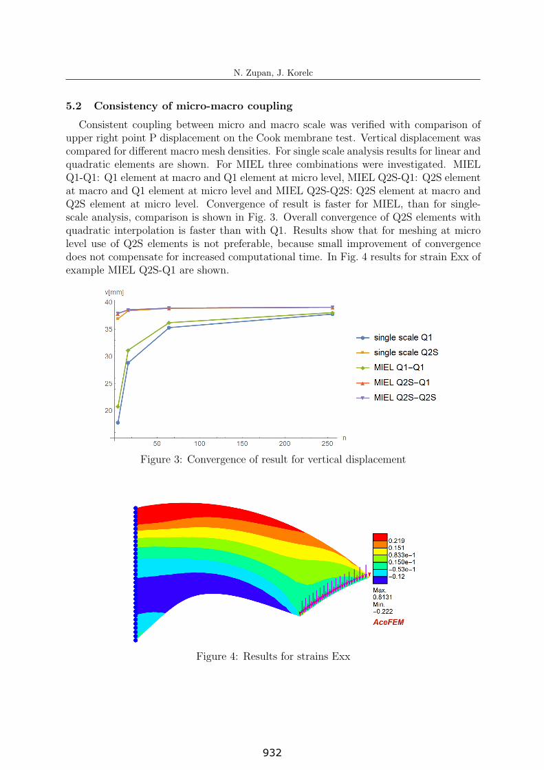
5.2 Consistency of micro-macro coupling
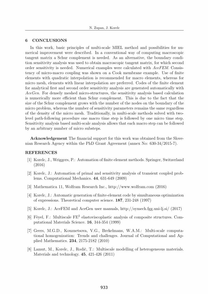
Consistent coupling between micro and macro scale was verified with comparison ofupper right point P displacement on the Cook membrane test. Vertical displacement wascompared for different macro mesh densities. For single scale analysis results for linear andquadratic elements are shown. For MIEL three combinations were investigated. MIELQ1-Q1: Q1 element at macro and Q1 element at micro level, MIEL Q2S-Q1: Q2S elementat macro and Q1 element at micro level and MIEL Q2S-Q2S: Q2S element at macro andQ2S element at micro level. Convergence of result is faster for MIEL, than for single-scale analysis, comparison is shown in Fig. 3. Overall convergence of Q2S elements withquadratic interpolation is faster than with Q1. Results show that for meshing at microlevel use of Q2S elements is not preferable, because small improvement of convergencedoes not compensate for increased computational time. In Fig. 4 results for strain Exx ofexample MIEL Q2S-Q1 are shown.
Figure 3: Convergence of result for vertical displacement
Figure 4: Results for strains Exx
7
932
N. Zupan, J. Korelc
6 CONCLUSIONS
In this work, basic principles of multi-scale MIEL method and possibilities for nu-merical improvement were described. In a conventional way of computing macroscopictangent matrix a Schur complement is needed. As an alternative, the boundary condi-tion sensitivity analysis was used to obtain macroscopic tangent matrix, for which secondorder sensitivity is needed. Numerical examples were calculated with AceFEM. Consis-tency of micro-macro coupling was shown on a Cook membrane example. Use of finiteelements with quadratic interpolation is recommended for macro elements, whereas formicro mesh, elements with linear interpolation are preferred. Codes of the finite elementfor analytical first and second order sensitivity analysis are generated automatically withAceGen. For densely meshed micro-structures, the sensitivity analysis based calculationis numerically more efficient than Schur complement. This is due to the fact that thesize of the Schur complement grows with the number of the nodes on the boundary of themicro problem, whereas the number of sensitivity parameters remains the same regardlessof the density of the micro mesh. Traditionally, in multi-scale methods solved with two-level path-following procedure one macro time step is followed by one micro time step.Sensitivity analysis based multi-scale analysis allows that each macro step can be followedby an arbitrary number of micro substeps.
Acknowledgement The financial support for this work was obtained from the Slove-nian Research Agency within the PhD Grant Agreement (annex No: 630-34/2015-7).
REFERENCES
[1] Korelc, J., Wriggers, P.: Automation of finite element methods. Springer, Switzerland(2016)
[2] Korelc, J.: Automation of primal and sensitivity analysis of transient coupled prob-lems. Computational Mechanics. 44, 631-649 (2009)
[3] Mathematica 11, Wolfram Research Inc., http://www.wolfram.com (2016)
[4] Korelc, J.: Automatic generation of finite-element code by simultaneous optimizationof expressions. Theoretical computer science. 187, 231-248 (1997)
[5] Korelc, J.: AceFEM and AceGen user manuals, http://symech.fgg.uni-lj.si/ (2017)
[6] Feyel, F.: Multiscale FE2 elastoviscoplastic analysis of composite structures. Com-putational Materials Science. 16, 344-354 (1999)
[7] Geers, M.G.D., Kouznetsova, V.G., Brekelmans, W.A.M.: Multi-scale computa-tional homogenization: Trends and challenges. Journal of Computational and Ap-plied Mathematics. 234, 2175-2182 (2010)
[8] Lamut, M., Korelc, J., Rodic, T.: Multiscale modelling of heterogeneous materials.Materials and technology. 45, 421-426 (2011)
8
933
N. Zupan, J. Korelc
[9] Kouznetsova, V., Brekelmans, W.A.M., Baaijens F.P.T.: An approach to micro-macro modelling of heterogeneous materials. Computational Machanics. 27, 37-48(2001)
[10] Miehe, C., Schotte, J., Schroder, J.: Computational Micro-Macro Transitions andOverall Moduli in the Analysis of Polycrystals at Large Strains. Computational Ma-terials Science. 16, 372-382 (1999)
[11] Solinc, U., Korelc, J.: A simple way to improved formulation of FE2 analysis. Com-putational Mechanics. 56, 905-915 (2015)
[12] Markovic, D., Ibrahimbegovic, A.: On micro-macro interface conditions for microscale based FEM for inelastic behaviour of heterogeneous materials. Computer meth-ods in applied mechanics and engineering. 193, 5503-5523 (2004)
9
934