Embed Size (px)
Citation preview

For additional information, refer to . . .
Control Supplement and Gas Control Partsfor EG/PEG – Natural gas only for EGH – Natural or Liquefied Petroleum (Propane) gas(tankless heater application optional)
EGPEG
EGH
• Installation
• Startup
• Maintenance
• PartsBoiler Manual
This manual must only be used by a qualified heating installer/service technician. Before installing, read all instructions, including this manual, the burner manual and any related supplements. Perform steps in the order given. Failure to comply could result in severe personal injury, death or substantial property damage.
EG/PEG/EGH Series 5
Gas-Fired Boilers
Part No. 550-142-905/0117
Part Number 550-142-905/01172
Contents
The following defined terms are used throughout this manual to bring attention to the presence of hazards of various risk levels, or to important information concerning the life of the product.
Indicates presence of hazards that will cause severe personal injury, death or substantial property damage.
Indicates presence of hazards that can cause severe personal injury, death or substantial property damage.
Indicates presence of hazards that will or can cause minor personal injury or property damage.
Indicates special instructions on installation, operation or maintenance that are important but not related to personal injury or property damage.
Hazard Defintions 2
Read this page first 4
Codes and Checklist 4
Prepare boiler location 5
Prepare the boiler 9
Connect piping — water boilers 14
Connect piping — steam boilers 17
Install boiler controls 20
Connect piping — tankless heater 21
Connect gas supply piping 22
Connect field wiring to boiler 23
Start-up 24
Department of Energy – Compliance . . . . . . . . . . . . . . . . . . . . . . . . . . . . 28
Service and maintenance 29
Handling fiberglass and ceramic fiber materials . . . . . . . . . . . . . . . . . . . .33
Replacement parts — EG/PEG 34
Replacement parts — EGH 36
Dimensional data 38
Ratings 39
Standard and optional equipment 40
Hazard definitions
EG & PEG sEriEs 5 • EGH sEriEs 5 Gas-firEd boilErs — boilEr manual
Part Number 550-142-905/0117 3
Read this page first
Failure to adhere to the guidelines below can result in severe personal injury, death or substantial property damage.
When servicing boiler —
To avoid electric shock, disconnect all electrical supplies to the boiler before performing maintenance.
To avoid severe burns, allow boiler to cool before performing maintenance.
This boiler contains ceramic fiber and fiberglass materials. Refer to the WARN-ING and instructions on page 33.
Boiler operation —Do not block flow of combustion or ven-tilation air to boiler.
Should overheating occur or gas supply fail to shut off, do not turn off or discon-nect electrical supply to pump. Instead, shut off the gas supply at a location ex-ternal to the appliance.
Combustion air —
DO NOT install combustion air intake where there is a risk of combustion air contamination.
Boiler water —
Do not use petroleum-based cleaning or sealing compounds in boiler system. Gaskets and seals in the system may be damaged. This can result in substantial property damage.
DO NOT use “ homemade cures ” or “ boiler patent medicines”. Serious dam-age to boiler, personnel and/or property may result.
Continual fresh make-up water will re-duce boiler life. Mineral buildup in eat exchanger reduces heat transfer, overheats the aluminum heat exchanger, and causes failure. Addition of oxygen carried in by make-up water can cause internal cor-rosion. Leaks in boiler or piping must be repaired at once to prevent make-up water. Use this boiler ONLY in a closed-loop system.
Do not add cold water to a hot boiler. Thermal shock can cause sections to crack.
Freeze protection fluids —NEVER use automotive or standard
glycol antifreeze. Use only freeze-protection fluids made for hydronic systems. Follow all guidelines given by the antifreeze manufacturer. Thoroughly clean and flush any re-placement boiler system that has used glycol before installing the new boiler
Frozen Water Damage Hazard
Residences or buildings that are unat-tended in severely cold weather, boiler system components failures, power out-ages, or other electrical system failures could result in frozen plumbing and water damage in a matter of hours. For your protection, take preventative actions such as having a security system installed that operates during power outages, senses low temperature, and initiates an effective ac-tion. Consult with your boiler contractor or a home security agency.
If any part of a boiler, burner or its controls has been sprayed with or submerged under water, either partially or fully, DO NOT attempt to op-erate the boiler until the boiler has been either replaced or completely repaired, inspected, and you are sure that the boiler and all components are in good condition and fully reliable.
Otherwise, by operating this boiler, you will cause a fire or explosion hazard, and an electrical shock hazard, leading to serious injury, death, or substantial property damage. See the instructions at right.
Saltwater Damage — The exposure of boiler components to saltwater can have both immediate and long-term effects. While the immediate effects of saltwater damage are similar to those of fresh-water (shorting out of electrical components, washing out of critical lubricants, etc.), the salt and other contaminants left behind can lead to longer term issues after the water is gone due to the conductive and corrosive nature of the salt residue. Therefore, Weil-McLain equipment contaminated with saltwater or polluted water will no longer be covered under warranty and should be replaced.
Electrical Damage — If any electrical component or wiring came into contact with water, or was suspected to have come into contact with water, replace the boiler with a new Weil-McLain boiler.
Installer— Read all instructions, including this manual and all other information shipped with the boiler, before installing. Perform steps in the order given.
User — This manual is for use only by a qualified heating installer/service technician. Refer to User’s Information Manual for your reference.
User — Have this boiler serviced/inspected by a qualified service technician, at least annually.
Failure to comply with the above could result in severe personal injury, death or substantial property damage.
Improper installation, adjustment, alteration, ser-vice or maintenance can cause property damage, personal injury, exposure to hazardous materials, or loss of life. Installation and service must be performed by a qualified installer, service agency or the gas supplier who must read and follow the supplied instructions before installing, servicing or removing this boiler. This boiler contains possibly carcinogenic, to humans.
Write in the CP number in the space provided on the Installation and Service Certificatee on page 27, if not already shown.
When calling or writing about the boiler— Please have the boiler model number from the boiler rating label and the CP number from the boiler jacket.
Consider piping and installation when determining boiler location.
Any claims for damage or shortage in shipment must be filed immediately against the transportation company by the consignee.
EG and EGH boilers for tankless or storage heater application are available only on special order as factory-installed optional equipment. Tankless heater cannot be added to standard block assem-bly. Block assembly must be ordered with heater openings. Standard boilers cannot be adapted for heater use.
EG & PEG sEriEs 5 • EGH sEriEs 5 Gas-firEd boilErs — boilEr manual
Part Number 550-142-905/01174
Installation must follow these codes:• Local, state, provincial, and national codes, laws, regulations and ordinances.• National Fuel Gas Code, ANSI Z223.1/NFPA 54 - latest edition.• National Electrical Code.• Canadian installations must comply with the Natural Gas and Propane Installation Code,
CAN/CSA B149.1 or B149.2 Installation Codes.
• Where required by the authority having jurisdiction, the installation must conform to the Standard for Controls and Safety Devices for Automatically Fired Boilers, ANSI/ASME CSD1.
The equipment shall be installed in accordance with those installation regulations in force in the local area where the installation is to be made. These shall be carefully followed in all cases. Authorities having jurisdiction shall be consulted before installations are made.
Commonwealth of MassachusettsWhen the boiler is installed within the Commonwealth of Massachusetts:
• This product must be installed by a licensed plumber.
• If antifreeze is used, a reduced pressure back-flow preventer device shall be used.
Certification
Safe operating and other performance criteria were met with the gas manifold and control assembly provided on boiler when boiler underwent tests specified in ANSI Z21.13 - latest edition.
Before locating the boiler:
❏ Check for nearby connection to:
• Venting connections
• Gas supply piping
• Electrical power
❏ Check area around boiler. Remove any combustible materials, gasoline and other flammable liquids.
Failure to keep boiler area clear and free of combustible materials, gasoline and other flammable liquids and vapors can result in severe personal injury, death or substantial property damage.
❏ Boiler must be installed so that gas control system components are protected from dripping or spraying water or rain during operation or service.
❏ If new boiler will replace existing boiler, check for and correct system problems, such as:
• System leaks causing oxygen corrosion or section cracks from hard water deposits.
Glycol — potential fire hazard —All glycol is flammable when exposed to high temperatures. If glycol is allowed to accumulate in or around the boiler or any other potential ignition source, a fire can develop. In order to prevent potential severe personal injury, death or substantial property damage from fire and/or structural damage:
• Never store glycol of any kind near the boiler or any potential ignition source.
• Monitor and inspect the system and boiler regularly for leakage. Repair any leaks immedi-ately to prevent possible accumulation of glycol.
Codes & Checklist
EG & PEG sEriEs 5 • EGH sEriEs 5 Gas-firEd boilErs — boilEr manual
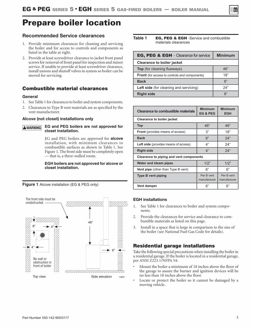
Figure 1 Alcove installation (EG & PEG only)
EGH installations
1. See Table 1 for clearances to boiler and system compo-nents.
2. Provide the clearances for service and clearance to com-bustible materials as listed on this page.
3. Install in a space that is large in comparison to the size of the boiler (see National Fuel Gas Code for details).
Part Number 550-142-905/0117 5
Table 1 EG, PEG & EGH -Service and combustible materials clearances
Prepare boiler locationRecommended Service clearances
1. Provide minimum clearances for cleaning and servicing the boiler and for access to controls and components as listed in the table at right.
2. Provide at least screwdriver clearance to jacket front panel screws for removal of front panel for inspection and minor service. If unable to provide at least screwdriver clearance, install unions and shutoff valves in system so boiler can be moved for servicing.
Combustible material clearances
General1. See Table 1 for clearances to boiler and system components.
2. Clearances to Type B vent materials are as specified by the vent manufacturer.
Alcove (not closet) installations only
EG and PEG boilers are not approved for closet installation.
EG and PEG boilers are approved for alcove installation, with minimum clearances to combustible surfaces as shown in Table 1. See Figure 1. The front side must be completely open — that is, a three-walled room.
EGH boilers are not approved for alcove or closet installation.
EG, PEG & EGH - Clearance for service MinimumClearance to boiler jacketTop (for cleaning flueways) 46”
Front (for access to controls and components) 18”
Back 6”
Left side (for cleaning and servicing) 24”
Right side 6”
Clearance to combustible materials MinimumEG & PEG
MinimumEGH
Clearance to boiler jacket
Top 46” 46”Front (provides means of access) 3” 18”Back 6” 24”Left side (provides means of access) 4” 24”Right side 4” 24”Clearance to piping and vent components
Water and steam pipes 1/2” 1/2”Vent pipe (other than Type B vent) 6” 6”Type B vent piping Per B vent
manufacturerPer B vent
manufacturer
Vent damper 6” 6”
Residential garage installationsTake the following special precautions when installing the boiler in a residential garage. If the boiler is located in a residential garage, per ANSI Z223.1/NFPA 54:
• Mount the boiler a minimum of 18 inches above the floor of the garage to assure the burner and ignition devices will be no less than 18 inches above the floor.
• Locate or protect the boiler so it cannot be damaged by a moving vehicle.
EG & PEG sEriEs 5 • EGH sEriEs 5 Gas-firEd boilErs — boilEr manual
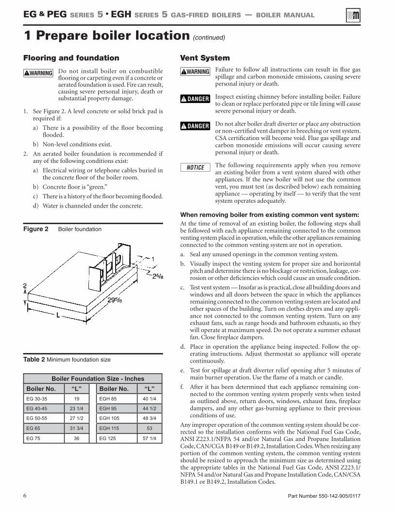
Table 2 Minimum foundation size
Figure 2 Boiler foundation
Part Number 550-142-905/01176
Vent System Failure to follow all instructions can result in flue gas
spillage and carbon monoxide emissions, causing severe personal injury or death.
Inspect existing chimney before installing boiler. Failure to clean or replace perforated pipe or tile lining will cause severe personal injury or death.
Do not alter boiler draft diverter or place any obstruction or non-certified vent damper in breeching or vent system. CSA certification will become void. Flue gas spillage and carbon monoxide emissions will occur causing severe personal injury or death.
The following requirements apply when you remove an existing boiler from a vent system shared with other appliances. If the new boiler will not use the common vent, you must test (as described below) each remaining appliance — operating by itself — to verify that the vent system operates adequately.
When removing boiler from existing common vent system:At the time of removal of an existing boiler, the following steps shall be followed with each appliance remaining connected to the common venting system placed in operation, while the other appliances remaining connected to the common venting system are not in operation.
a. Seal any unused openings in the common venting system.
b. Visually inspect the venting system for proper size and horizontal pitch and determine there is no blockage or restriction, leakage, cor-rosion or other deficiencies which could cause an unsafe condition.
c. Test vent system — Insofar as is practical, close all building doors and windows and all doors between the space in which the appliances remaining connected to the common venting system are located and other spaces of the building. Turn on clothes dryers and any appli-ance not connected to the common venting system. Turn on any exhaust fans, such as range hoods and bathroom exhausts, so they will operate at maximum speed. Do not operate a summer exhaust fan. Close fireplace dampers.
d. Place in operation the appliance being inspected. Follow the op-erating instructions. Adjust thermostat so appliance will operate continuously.
e. Test for spillage at draft diverter relief opening after 5 minutes of main burner operation. Use the flame of a match or candle.
f. After it has been determined that each appliance remaining con-nected to the common venting system properly vents when tested as outlined above, return doors, windows, exhaust fans, fireplace dampers, and any other gas-burning appliance to their previous conditions of use.
Any improper operation of the common venting system should be cor-rected so the installation conforms with the National Fuel Gas Code, ANSI Z223.1/NFPA 54 and/or Natural Gas and Propane Installation Code, CAN/CGA B149 or B149.2, Installation Codes. When resizing any portion of the common venting system, the common venting system should be resized to approach the minimum size as determined using the appropriate tables in the National Fuel Gas Code, ANSI Z223.1/NFPA 54 and/or Natural Gas and Propane Installation Code, CAN/CSA B149.1 or B149.2, Installation Codes.
Flooring and foundation
Do not install boiler on combustible flooring or carpeting even if a concrete or aerated foundation is used. Fire can result, causing severe personal injury, death or substantial property damage.
1. See Figure 2. A level concrete or solid brick pad is required if:
a) There is a possibility of the floor becoming flooded.
b) Non-level conditions exist.
2. An aerated boiler foundation is recommended if any of the following conditions exist:
a) Electrical wiring or telephone cables buried in the concrete floor of the boiler room.
b) Concrete floor is “green.”
c) There is a history of the floor becoming flooded.
d) Water is channeled under the concrete.
1 Prepare boiler location (continued)
Boiler Foundation Size - InchesBoiler No. “L” Boiler No. “L”EG 30-35 19 EGH 85 40 1/4
EG 40-45 23 1/4 EGH 95 44 1/2
EG 50-55 27 1/2 EGH 105 48 3/4
EG 65 31 3/4 EGH 115 53
EG 75 36 EG 125 57 1/4
EG & PEG sEriEs 5 • EGH sEriEs 5 Gas-firEd boilErs — boilEr manual
Part Number 550-142-905/0117 7
Products to avoidSpray cans containing chloro/fluorocarbons
Permanent wave solutions
Chlorinated waxes/cleaners
Chlorine-based swimming pool chemicals
Calcium chloride used for thawing
Sodium chloride used for water softening
Refrigerant leaks
Paint or varnish removers
Hydrochloric acid/muriatic acid
Cements and glues
Antistatic fabric softeners used in clothes dryers
Chlorine-type bleaches, detergents, and cleaning solvents found in household laundry rooms
Adhesives used to fasten building products and other similar products
Areas likely to have contaminantsDry cleaning/laundry areas and establishments
Swimming pools
Metal fabrication plants
Beauty shops
Refrigeration repair shops
Photo processing plants
Auto body shops
Plastic manufacturing plants
Furniture refinishing areas and establishments
New building construction
Remodeling areas
Garages with workshops
Buildings under construction (where air is contaminated with particulates)
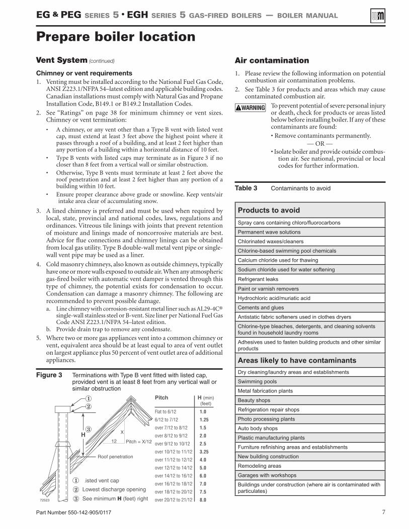
Figure 3 Terminations with Type B vent fitted with listed cap, provided vent is at least 8 feet from any vertical wall or similar obstruction
Vent System (continued)
Chimney or vent requirements1. Venting must be installed according to the National Fuel Gas Code,
ANSI Z223.1/NFPA 54–latest edition and applicable building codes. Canadian installations must comply with Natural Gas and Propane Installation Code, B149.1 or B149.2 Installation Codes.
2. See “Ratings” on page 38 for minimum chimney or vent sizes. Chimney or vent termination:
• A chimney, or any vent other than a Type B vent with listed vent cap, must extend at least 3 feet above the highest point where it passes through a roof of a building, and at least 2 feet higher than any portion of a building within a horizontal distance of 10 feet.
• Type B vents with listed caps may terminate as in Figure 3 if no closer than 8 feet from a vertical wall or similar obstruction.
• Otherwise, Type B vents must terminate at least 2 feet above the roof penetration and at least 2 feet higher than any portion of a building within 10 feet.
• Ensure proper clearance above grade or snowline. Keep vents/air intake area clear of accumulating snow.
3. A lined chimney is preferred and must be used when required by local, state, provincial and national codes, laws, regulations and ordinances. Vitreous tile linings with joints that prevent retention of moisture and linings made of noncorrosive materials are best. Advice for flue connections and chimney linings can be obtained from local gas utility. Type B double-wall metal vent pipe or single-wall vent pipe may be used as a liner.
4. Cold masonry chimneys, also known as outside chimneys, typically have one or more walls exposed to outside air. When any atmospheric gas-fired boiler with automatic vent damper is vented through this type of chimney, the potential exists for condensation to occur. Condensation can damage a masonry chimney. The following are recommended to prevent possible damage.a. Line chimney with corrosion-resistant metal liner such as AL29-4C®
single-wall stainless steel or B-vent. Size liner per National Fuel Gas Code ANSI Z223.1/NFPA 54–latest edition.
b. Provide drain trap to remove any condensate.
5. Where two or more gas appliances vent into a common chimney or vent, equivalent area should be at least equal to area of vent outlet on largest appliance plus 50 percent of vent outlet area of additional appliances.
Air contamination
1. Please review the following information on potential combustion air contamination problems.
2. See Table 3 for products and areas which may cause contaminated combustion air.
To prevent potential of severe personal injury or death, check for products or areas listed below before installing boiler. If any of these contaminants are found:
• Remove contaminants permanently. — OR —
• Isolate boiler and provide outside combus-tion air. See national, provincial or local codes for further information.
Prepare boiler location
Table 3 Contaminants to avoid
EG & PEG sEriEs 5 • EGH sEriEs 5 Gas-firEd boilErs — boilEr manual
Part Number 550-142-905/01178
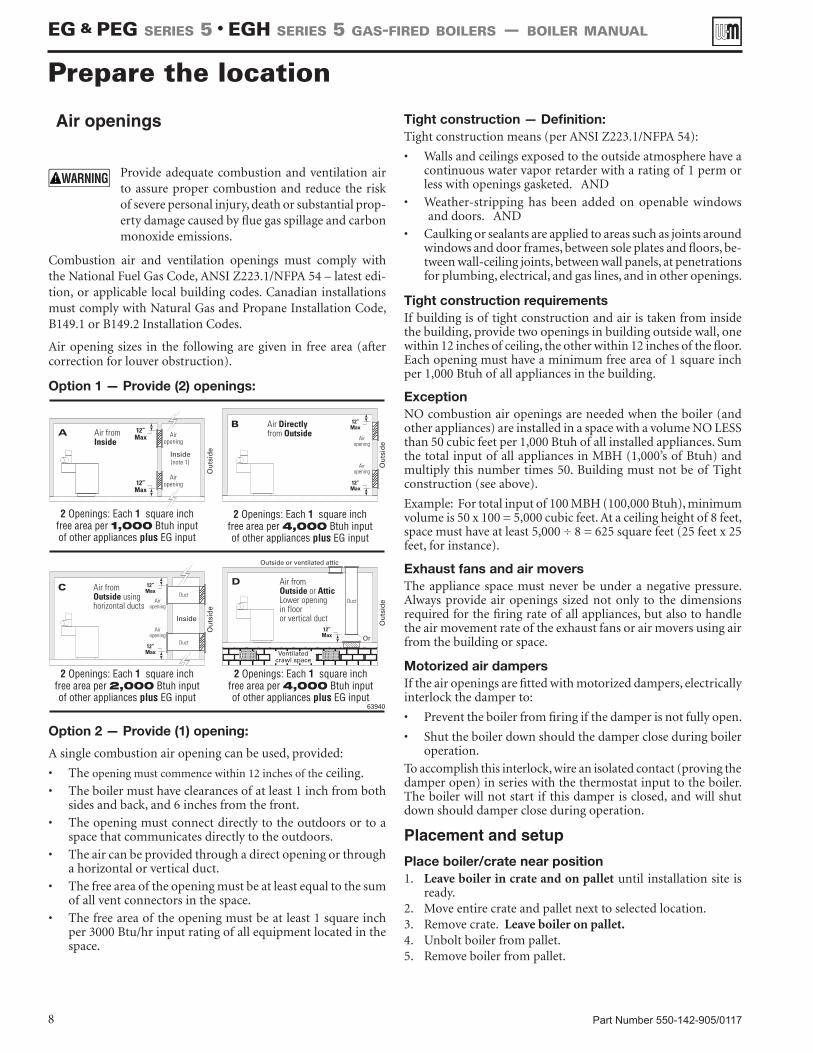
Air openings
Provide adequate combustion and ventilation air to assure proper combustion and reduce the risk of severe personal injury, death or substantial prop-erty damage caused by flue gas spillage and carbon monoxide emissions.
Combustion air and ventilation openings must comply with the National Fuel Gas Code, ANSI Z223.1/NFPA 54 – latest edi-tion, or applicable local building codes. Canadian installations must comply with Natural Gas and Propane Installation Code, B149.1 or B149.2 Installation Codes.
Air opening sizes in the following are given in free area (after correction for louver obstruction).
Option 1 — Provide (2) openings:
Option 2 — Provide (1) opening:
A single combustion air opening can be used, provided:
• The opening must commence within 12 inches of the ceiling.
• The boiler must have clearances of at least 1 inch from both sides and back, and 6 inches from the front.
• The opening must connect directly to the outdoors or to a space that communicates directly to the outdoors.
• The air can be provided through a direct opening or through a horizontal or vertical duct.
• The free area of the opening must be at least equal to the sum of all vent connectors in the space.
• The free area of the opening must be at least 1 square inch per 3000 Btu/hr input rating of all equipment located in the space.
Tight construction — Definition:Tight construction means (per ANSI Z223.1/NFPA 54):
• Walls and ceilings exposed to the outside atmosphere have a continuous water vapor retarder with a rating of 1 perm or less with openings gasketed. AND
• Weather-stripping has been added on openable windows and doors. AND
• Caulking or sealants are applied to areas such as joints around windows and door frames, between sole plates and floors, be-tween wall-ceiling joints, between wall panels, at penetrations for plumbing, electrical, and gas lines, and in other openings.
Tight construction requirementsIf building is of tight construction and air is taken from inside the building, provide two openings in building outside wall, one within 12 inches of ceiling, the other within 12 inches of the floor. Each opening must have a minimum free area of 1 square inch per 1,000 Btuh of all appliances in the building.
ExceptionNO combustion air openings are needed when the boiler (and other appliances) are installed in a space with a volume NO LESS than 50 cubic feet per 1,000 Btuh of all installed appliances. Sum the total input of all appliances in MBH (1,000’s of Btuh) and multiply this number times 50. Building must not be of Tight construction (see above).
Example: For total input of 100 MBH (100,000 Btuh), minimum volume is 50 x 100 = 5,000 cubic feet. At a ceiling height of 8 feet, space must have at least 5,000 ÷ 8 = 625 square feet (25 feet x 25 feet, for instance).
Exhaust fans and air moversThe appliance space must never be under a negative pressure. Always provide air openings sized not only to the dimensions required for the firing rate of all appliances, but also to handle the air movement rate of the exhaust fans or air movers using air from the building or space.
Motorized air dampersIf the air openings are fitted with motorized dampers, electrically interlock the damper to:
• Prevent the boiler from firing if the damper is not fully open.
• Shut the boiler down should the damper close during boiler operation.
To accomplish this interlock, wire an isolated contact (proving the damper open) in series with the thermostat input to the boiler. The boiler will not start if this damper is closed, and will shut down should damper close during operation.
Placement and setup
Place boiler/crate near position1. Leave boiler in crate and on pallet until installation site is
ready.2. Move entire crate and pallet next to selected location.3. Remove crate. Leave boiler on pallet.4. Unbolt boiler from pallet.5. Remove boiler from pallet.
Prepare the location
EG & PEG sEriEs 5 • EGH sEriEs 5 Gas-firEd boilErs — boilEr manual
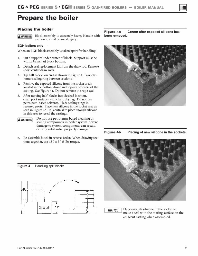
Figure 4 Handling split blocks
Part Number 550-142-905/0117 9
Placing the boiler
Block assembly is extremely heavy. Handle with caution to avoid personal injury.
EGH boilers only —
When an EGH block assembly is taken apart for handling:
1. Put a support under center of block. Support must be within ½ inch of block bottom.
2. Detach seal replacement kit from the draw rod. Remove short center draw rods.
3. Tip half blocks on end as shown in Figure 4. Save elas-tomer sealing ring between sections.
4. Remove the exposed silicone from the socket areas located in the bottom-front and top-rear corners of the casting. See Figure 4a. Do not remove the rope seal.
5. After moving half-blocks into desired location, clean port surfaces with clean, dry rag. Do not use petroleum-based solvents. Place sealing rings in recessed ports. Place new silicone in the socket area as seen in Figure 4b. It is critical to place enough silicone in this area to reseal the castings.
Do not use petroleum-based cleaning or sealing compounds in boiler system. Severe damage to system components can result, causing substantial property damage.
6. Re-assemble block in reverse order. When drawing sec-tions together, use 45 ( ± 5 ) ft-lbs torque.
1
Figure 4a Corner after exposed silicone has been removed.
Figure 4b Placing of new silicone in the sockets.
Place enough silicone in the socket to make a seal with the mating surface on the adjacent casting when assembled.
Prepare the boiler
EG & PEG sEriEs 5 • EGH sEriEs 5 Gas-firEd boilErs — boilEr manual
Part Number 550-142-905/011710
Hydrostatic pressure testPressure test before attaching gas piping or electrical supply.
1. Plug any necessary boiler tappings or openings.
2. Do not use gauge supplied with boiler for pressure testing. Install gauge with appropriate range.
3. Fill boiler with water. Vent all air. Test steam boilers between 45 - 55 psi. Test water boilers at 1-1/2 times maximum work-ing pressure.
Do not leave boiler unattended. A cold water fill could expand and cause excessive pressure, resulting in severe personal injury, death or substantial property damage.
4. Verify gauge pressure is maintained. Check for leaks. Repair if found.
Leaks must be repaired at once. Failure to do so can cause boiler damage, resulting in substantial property damage.
Do not use petroleum-based sealing compounds in boiler system. Severe damage to boiler will result, causing substantial property damage.
5. Drain boiler and repair leaks if found.
6. Retest boiler after repairing leaks.
7. Remove plugs from any tappings that will be used for controls and accessories. Refer to Table 4 and Figure 5.
8. On initial start-up check for leaks in the system piping. If found, repair at once.
Installation of flue baffles (EGH only)1. Bend the two (2) tabs on the flue baffle approx. 90 degrees in
opposite directions.
2. Slide flue baffles (notch down and to the back) in between each section.
The installer must install all flue baffles for proper boiler operation.
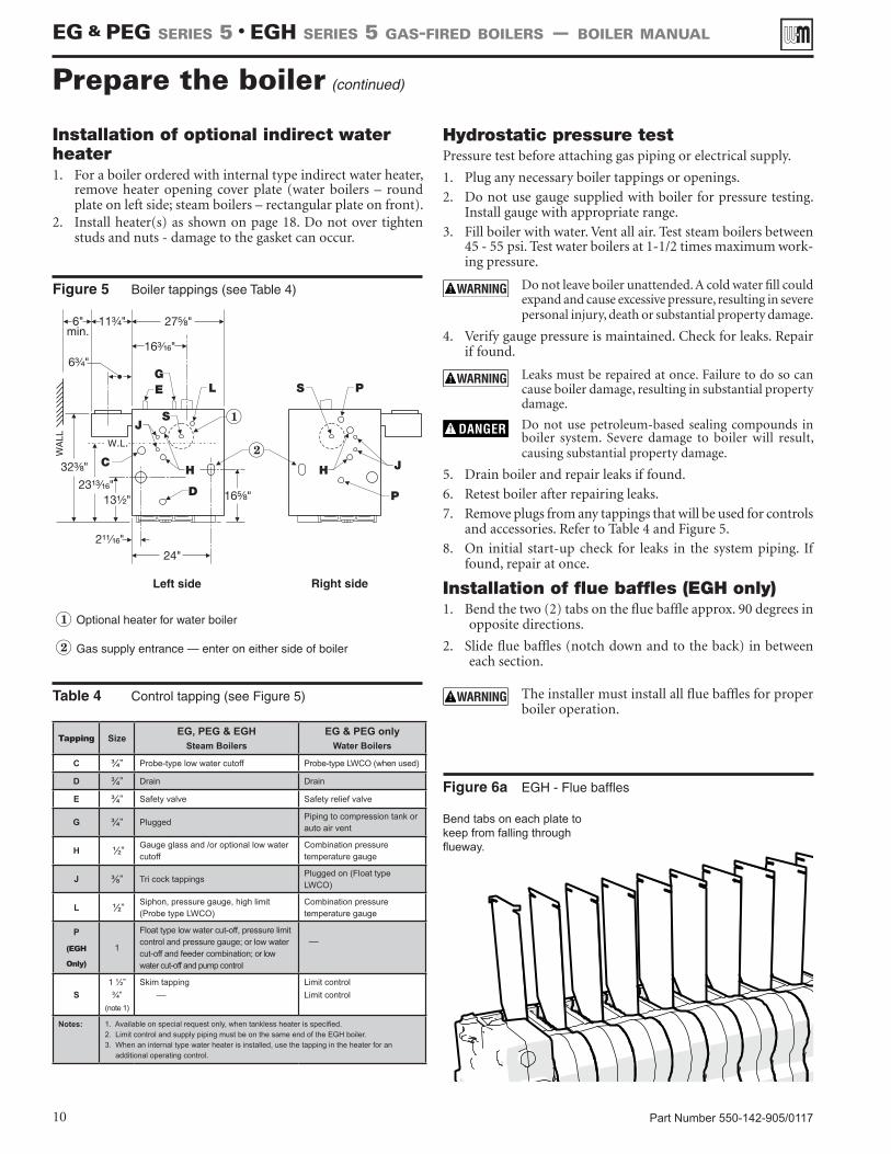
Figure 5 Boiler tappings (see Table 4)
Table 4 Control tapping (see Figure 5)
Prepare the boiler (continued)
Tapping SizeEG, PEG & EGH
Steam BoilersEG & PEG only
Water Boilers
C ¾” Probe-type low water cutoff Probe-type LWCO (when used)
D ¾” Drain Drain
E ¾” Safety valve Safety relief valve
G ¾” PluggedPiping to compression tank or auto air vent
H ½” Gauge glass and /or optional low water cutoff
Combination pressure temperature gauge
J ⅜” Tri cock tappingsPlugged on (Float type LWCO)
L ½” Siphon, pressure gauge, high limit (Probe type LWCO)
Combination pressure temperature gauge
P
(EGH
Only)
1
Float type low water cut-off, pressure limit control and pressure gauge; or low water cut-off and feeder combination; or low water cut-off and pump control
––
S1 ½”¾”
(note 1)
Skim tapping ––
Limit controlLimit control
Notes: 1. Available on special request only, when tankless heater is specified.2. Limit control and supply piping must be on the same end of the EGH boiler. 3. When an internal type water heater is installed, use the tapping in the heater for an additional operating control.
Figure 6a EGH - Flue baffles
Installation of optional indirect water heater1. For a boiler ordered with internal type indirect water heater,
remove heater opening cover plate (water boilers – round plate on left side; steam boilers – rectangular plate on front).
2. Install heater(s) as shown on page 18. Do not over tighten studs and nuts - damage to the gasket can occur.
EG & PEG sEriEs 5 • EGH sEriEs 5 Gas-firEd boilErs — boilEr manual
Bend tabs on each plate to keep from falling through flueway.
Part Number 550-142-905/0117 11
Installation of flue collector hood (Factory installed on PEG boilers)
Set flue collector hood on boiler as shown in Figure 6b. Use boiler cement furnished to provide gas-tight seal.
Failure to maintain gas-tight seal can cause flue gas spillage and carbon monoxide emissions, resulting in severe personal injury or death.
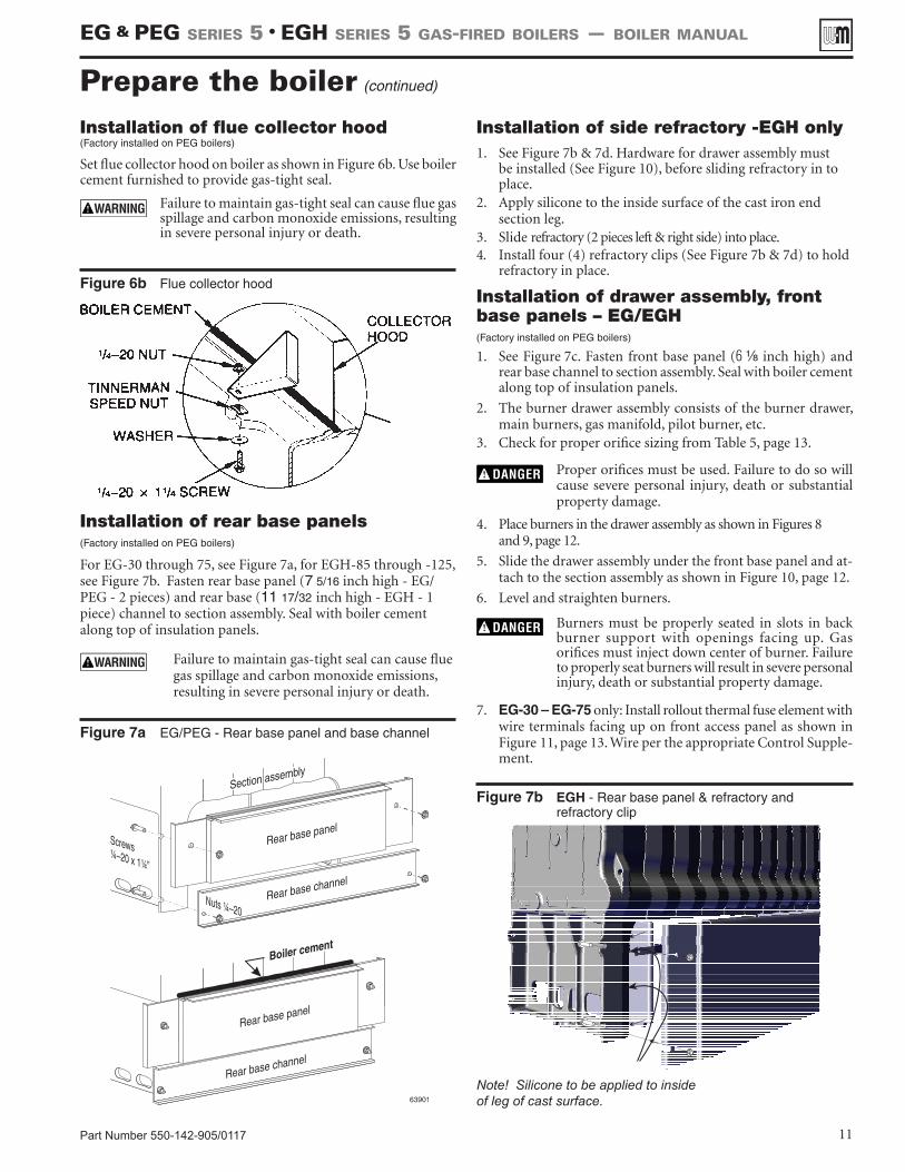
Installation of rear base panels
(Factory installed on PEG boilers)
For EG-30 through 75, see Figure 7a, for EGH-85 through -125, see Figure 7b. Fasten rear base panel (7 5/16 inch high - EG/PEG - 2 pieces) and rear base (11 17/32 inch high - EGH - 1 piece) channel to section assembly. Seal with boiler cement along top of insulation panels.
Failure to maintain gas-tight seal can cause flue gas spillage and carbon monoxide emissions, resulting in severe personal injury or death.
Figure 7a EG/PEG - Rear base panel and base channel
Prepare the boiler (continued)
Installation of side refractory -EGH only1. See Figure 7b & 7d. Hardware for drawer assembly must
be installed (See Figure 10), before sliding refractory in to place.
2. Apply silicone to the inside surface of the cast iron end section leg.
3. Slide refractory (2 pieces left & right side) into place.4. Install four (4) refractory clips (See Figure 7b & 7d) to hold
refractory in place.
Installation of drawer assembly, front base panels – EG/EGH
(Factory installed on PEG boilers)
1. See Figure 7c. Fasten front base panel (6 Z\, inch high) and rear base channel to section assembly. Seal with boiler cement along top of insulation panels.
2. The burner drawer assembly consists of the burner drawer, main burners, gas manifold, pilot burner, etc.
3. Check for proper orifice sizing from Table 5, page 13.
Proper orifices must be used. Failure to do so will cause severe personal injury, death or substantial property damage.
4. Place burners in the drawer assembly as shown in Figures 8 and 9, page 12.
5. Slide the drawer assembly under the front base panel and at-tach to the section assembly as shown in Figure 10, page 12.
6. Level and straighten burners.
Burners must be properly seated in slots in back burner support with openings facing up. Gas orifices must inject down center of burner. Failure to properly seat burners will result in severe personal injury, death or substantial property damage.
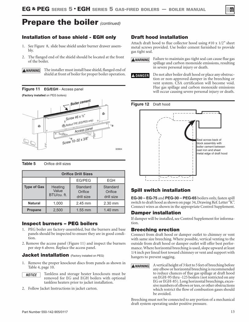
7. EG-30 – EG-75 only: Install rollout thermal fuse element with wire terminals facing up on front access panel as shown in Figure 11, page 13. Wire per the appropriate Control Supple-ment.
Figure 6b Flue collector hood
Figure 7b EGH - Rear base panel & refractory and refractory clip
EG & PEG sEriEs 5 • EGH sEriEs 5 Gas-firEd boilErs — boilEr manual
Note! Silicone to be applied to inside of leg of cast surface.
Part Number 550-142-905/011712
Prepare the boiler (continued)
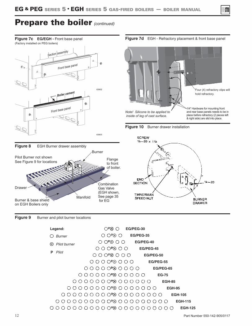
Figure 10 Burner drawer installation
Figure 9 Burner and pilot burner locations
Figure 8 EGH Burner drawer assembly
Figure 7c EG/EGH - Front base panel(Factory installed on PEG boilers)
Figure 7d EGH - Refractory placement & front base panel
EG & PEG sEriEs 5 • EGH sEriEs 5 Gas-firEd boilErs — boilEr manual
Burner
CombinationGas Valve(EGH shown,See page 35 for EGBurner & base shield
on EGH Boilers only
Manifold
Drawer
Pilot Burner not shownSee Figure 9 for locations
Four (4) refractory clips will hold refractory.
1/4” Hardware for mounting front and rear base panels needs to be in place before refractory (2 pieces left & right side) are slid into place.
Flange to front of boiler.
Note! Silicone to be applied to inside of leg of cast surface.
Part Number 550-142-905/0117 13
Figure 11 EG/EGH - Access panel
(Factory installed on PEG boilers)
Spill switch installation
EG-30 – EG-75 and PEG-30 – PEG-65 boilers only, fasten spill switch to draft hood as shown on page 34, Drawing Ref. Letter “K”. Connect wires as shown in the appropriate Control Supplement.
Damper installationIf damper will be installed, see Control Supplement for informa-tion.
Breeching erectionConnect from draft hood or damper outlet to chimney or vent with same size breeching. Where possible, vertical venting to the outside from draft hood or damper outlet will offer best perfor-mance. Where horizontal breeching is used, slope upward at least 1/4 inch per lineal foot toward chimney or vent and support with hangers to prevent sagging.
A vertical height of 3 feet to 5 feet of breeching before any elbow or horizontal breeching is recommended to reduce chances of flue gas spillage at draft hood on EGH-95 thru -125 boilers (not restricted on any EG or EGH-85). Long horizontal breechings, exces-sive numbers of elbows or tees, or other obstructions which restrict the flow of combustion gases should be avoided.
Breeching must not be connected to any portion of a mechanical draft system operating under positive pressure.
Inspect burners – PEG boilers1. PEG boiler are factory-assembled, but the burners and base
panels should be inspected to ensure they are in good condi-tion.
2. Remove the access panel (Figure 11) and inspect the burners per step 6 above. Replace the access panel.
Jacket installation (Factory installed on PEG)
1. Remove the proper knockout discs from panels as shown in Table 4, page 10.
Tankless and storage heater knockouts must be removed for EG and EGH boilers with optional tankless heaters prior to jacket installation.
2. Follow Jacket Instructions in jacket carton.
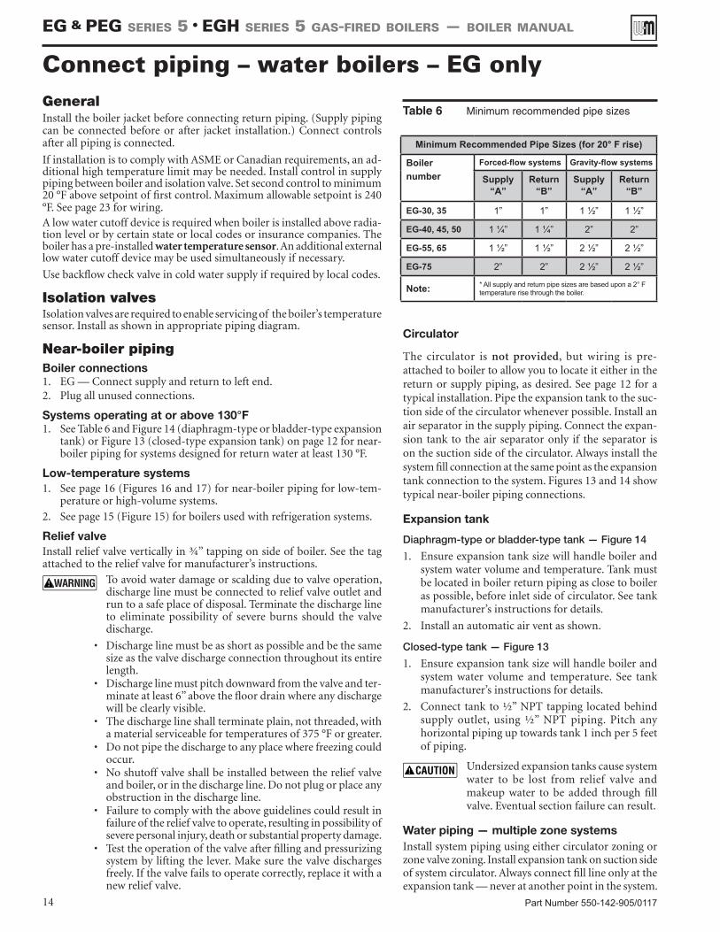
Figure 12 Draft hood
Prepare the boiler (continued)
Table 5 Orifice drill sizes
Orifice Drill SizesEG/PEG EGH
Type of Gas Heating Value
BTU/cu. ft.
Standard Orifice
drill size
Standard Orifice
drill size
Natural 1,000 2.45 mm 2.30 mm
Propane 2,500 1.55 mm 1.40 mm
Draft hood installationAttach draft hood to flue collector hood using #10 x 1/2” sheet metal screws provided. Use boiler cement furnished to provide gas tight seal.
Failure to maintain gas-tight seal can cause flue gas spillage and carbon monoxide emissions, resulting in severe personal injury or death.
Do not alter boiler draft hood or place any obstruc-tion or non-approved damper in the breeching or vent system. CSA certification will become void. Flue gas spillage and carbon monoxide emissions will occur causing severe personal injury or death.
Installation of base shield - EGH only
1. See Figure 8, slide base shield under burner drawer assem-bly.
2. The flanged end of the shield should be located at the front of the boiler.
The installer must install base shield, flanged end of shield at front of boiler for proper boiler operation.
EG & PEG sEriEs 5 • EGH sEriEs 5 Gas-firEd boilErs — boilEr manual
Seal across back of block assembly withboiler cement betweencast iron and sheetmetal edge of draft hood
Part Number 550-142-905/011714
GeneralInstall the boiler jacket before connecting return piping. (Supply piping can be connected before or after jacket installation.) Connect controls after all piping is connected.
If installation is to comply with ASME or Canadian requirements, an ad-ditional high temperature limit may be needed. Install control in supply piping between boiler and isolation valve. Set second control to minimum 20 °F above setpoint of first control. Maximum allowable setpoint is 240 °F. See page 23 for wiring.A low water cutoff device is required when boiler is installed above radia-tion level or by certain state or local codes or insurance companies. The boiler has a pre-installed water temperature sensor. An additional external low water cutoff device may be used simultaneously if necessary.
Use backflow check valve in cold water supply if required by local codes.
Isolation valvesIsolation valves are required to enable servicing of the boiler’s temperature sensor. Install as shown in appropriate piping diagram.
Near-boiler pipingBoiler connections1. EG — Connect supply and return to left end.2. Plug all unused connections.
Systems operating at or above 130°F1. See Table 6 and Figure 14 (diaphragm-type or bladder-type expansion
tank) or Figure 13 (closed-type expansion tank) on page 12 for near-boiler piping for systems designed for return water at least 130 °F.
Low-temperature systems1. See page 16 (Figures 16 and 17) for near-boiler piping for low-tem-
perature or high-volume systems.
2. See page 15 (Figure 15) for boilers used with refrigeration systems.
Relief valveInstall relief valve vertically in ¾” tapping on side of boiler. See the tag attached to the relief valve for manufacturer’s instructions.
To avoid water damage or scalding due to valve operation, discharge line must be connected to relief valve outlet and run to a safe place of disposal. Terminate the discharge line to eliminate possibility of severe burns should the valve discharge.
• Discharge line must be as short as possible and be the same size as the valve discharge connection throughout its entire length.
• Discharge line must pitch downward from the valve and ter-minate at least 6” above the floor drain where any discharge will be clearly visible.
• The discharge line shall terminate plain, not threaded, with a material serviceable for temperatures of 375 °F or greater.
• Do not pipe the discharge to any place where freezing could occur.
• No shutoff valve shall be installed between the relief valve and boiler, or in the discharge line. Do not plug or place any obstruction in the discharge line.
• Failure to comply with the above guidelines could result in failure of the relief valve to operate, resulting in possibility of severe personal injury, death or substantial property damage.
• Test the operation of the valve after filling and pressurizing system by lifting the lever. Make sure the valve discharges freely. If the valve fails to operate correctly, replace it with a new relief valve.
Circulator
The circulator is not provided, but wiring is pre-attached to boiler to allow you to locate it either in the return or supply piping, as desired. See page 12 for a typical installation. Pipe the expansion tank to the suc-tion side of the circulator whenever possible. Install an air separator in the supply piping. Connect the expan-sion tank to the air separator only if the separator is on the suction side of the circulator. Always install the system fill connection at the same point as the expansion tank connection to the system. Figures 13 and 14 show typical near-boiler piping connections.
Expansion tank
Diaphragm-type or bladder-type tank — Figure 14
1. Ensure expansion tank size will handle boiler and system water volume and temperature. Tank must be located in boiler return piping as close to boiler as possible, before inlet side of circulator. See tank manufacturer’s instructions for details.
2. Install an automatic air vent as shown.
Closed-type tank — Figure 13
1. Ensure expansion tank size will handle boiler and system water volume and temperature. See tank manufacturer’s instructions for details.
2. Connect tank to ½” NPT tapping located behind supply outlet, using ½” NPT piping. Pitch any horizontal piping up towards tank 1 inch per 5 feet of piping.
Undersized expansion tanks cause system water to be lost from relief valve and makeup water to be added through fill valve. Eventual section failure can result.
Water piping — multiple zone systemsInstall system piping using either circulator zoning or zone valve zoning. Install expansion tank on suction side of system circulator. Always connect fill line only at the expansion tank — never at another point in the system.
Table 6 Minimum recommended pipe sizes
Connect piping – water boilers – EG only
Minimum Recommended Pipe Sizes (for 20° F rise)
Boilernumber
Forced-flow systems Gravity-flow systems
Supply “A”
Return “B”
Supply “A”
Return “B”
EG-30, 35 1” 1” 1 ½” 1 ½”
EG-40, 45, 50 1 ¼” 1 ¼” 2” 2”
EG-55, 65 1 ½” 1 ½” 2 ½” 2 ½”
EG-75 2” 2” 2 ½” 2 ½”
Note: * All supply and return pipe sizes are based upon a 2° F temperature rise through the boiler.
EG & PEG sEriEs 5 • EGH sEriEs 5 Gas-firEd boilErs — boilEr manual
Part Number 550-142-905/0117 15
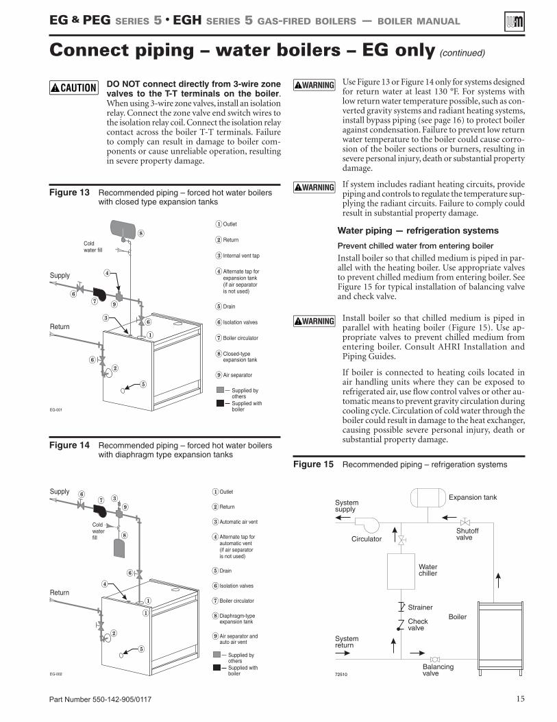
Figure 13 Recommended piping – forced hot water boilers with closed type expansion tanks
Figure 14 Recommended piping – forced hot water boilers with diaphragm type expansion tanks
Water piping — refrigeration systems
Prevent chilled water from entering boiler
Install boiler so that chilled medium is piped in par-allel with the heating boiler. Use appropriate valves to prevent chilled medium from entering boiler. See Figure 15 for typical installation of balancing valve and check valve.
Use Figure 13 or Figure 14 only for systems designed for return water at least 130 °F. For systems with low return water temperature possible, such as con-verted gravity systems and radiant heating systems, install bypass piping (see page 16) to protect boiler against condensation. Failure to prevent low return water temperature to the boiler could cause corro-sion of the boiler sections or burners, resulting in severe personal injury, death or substantial property damage.
If system includes radiant heating circuits, provide piping and controls to regulate the temperature sup-plying the radiant circuits. Failure to comply could result in substantial property damage.
Figure 15 Recommended piping – refrigeration systems
Install boiler so that chilled medium is piped in parallel with heating boiler (Figure 15). Use ap-propriate valves to prevent chilled medium from entering boiler. Consult AHRI Installation and Piping Guides.
If boiler is connected to heating coils located in air handling units where they can be exposed to refrigerated air, use flow control valves or other au-tomatic means to prevent gravity circulation during cooling cycle. Circulation of cold water through the boiler could result in damage to the heat exchanger, causing possible severe personal injury, death or substantial property damage.
Connect piping – water boilers – EG only (continued)
DO NOT connect directly from 3-wire zone valves to the T-T terminals on the boiler. When using 3-wire zone valves, install an isolation relay. Connect the zone valve end switch wires to the isolation relay coil. Connect the isolation relay contact across the boiler T-T terminals. Failure to comply can result in damage to boiler com-ponents or cause unreliable operation, resulting in severe property damage.
EG & PEG sEriEs 5 • EGH sEriEs 5 Gas-firEd boilErs — boilEr manual
Part Number 550-142-905/011716
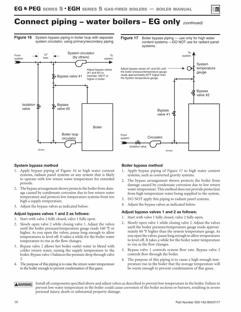
Figure 16 System bypass piping in boiler loop with separate system circulator, using primary/secondary piping.
Figure 17 Boiler bypass piping — use only for high water content systems —DO NOT use for radiant panel systems.
Connect piping – water boilers – EG only (continued)
Install all components specified above and adjust valves as described to prevent low temperature in the boiler. Failure to prevent low water temperature in the boiler could cause corrosion of the boiler sections or burners, resulting in severe personal injury, death or substantial property damage.
System bypass method1. Apply bypass piping of Figure 16 to high water content
systems, radiant panel systems or any system that is likely to operate with low return water temperature for extended periods.
2. The bypass arrangement shown protects the boiler from dam-age caused by condensate corrosion due to low return water temperature and protects low temperature systems from too high a supply temperature.
3. Adjust the bypass valves as indicated below.
Adjust bypass valves 1 and 2 as follows:1. Start with valve 2 fully closed, valve 1 fully open.
2. Slowly open valve 2 while closing valve 1. Adjust the valves until the boiler pressure/temperature gauge reads 160 °F or higher. As you open the valves, pause long enough to allow temperatures to level off. It takes a while for the boiler water temperature to rise as the flow changes.
3. Bypass valve 2 allows hot boiler outlet water to blend with colder return water, raising the supply temperature to the boiler. Bypass valve 1 balances the pressure drop through valve 2.
4. The purpose of this piping is to raise the return water temperature to the boiler enough to prevent condensation of flue gases.
Boiler bypass method1. Apply bypass piping of Figure 17 to high water content
systems, such as converted gravity systems.
2. The bypass arrangement shown protects the boiler from damage caused by condensate corrosion due to low return water temperature. This method does not provide protection from high temperature water being supplied to the system.
3. DO NOT apply this piping to radiant panel systems.
4. Adjust the bypass valves as indicated below.
Adjust bypass valves 1 and 2 as follows:1. Start with valve 1 fully closed, valve 2 fully open.
2. Slowly open valve 1 while closing valve 2. Adjust the valves until the boiler pressure/temperature gauge reads approxi-mately 60 °F higher than the system temperature gauge. As you open the valves, pause long enough to allow temperatures to level off. It takes a while for the boiler water temperature to rise as the flow changes.
3. Bypass valve 1 controls system flow rate. Bypass valve 2 controls flow through the boiler.
4. The purpose of this piping is to cause a high enough tem-perature rise in the boiler that the average temperature will be warm enough to prevent condensation of flue gases.
EG & PEG sEriEs 5 • EGH sEriEs 5 Gas-firEd boilErs — boilEr manual
Part Number 550-142-905/0117 17
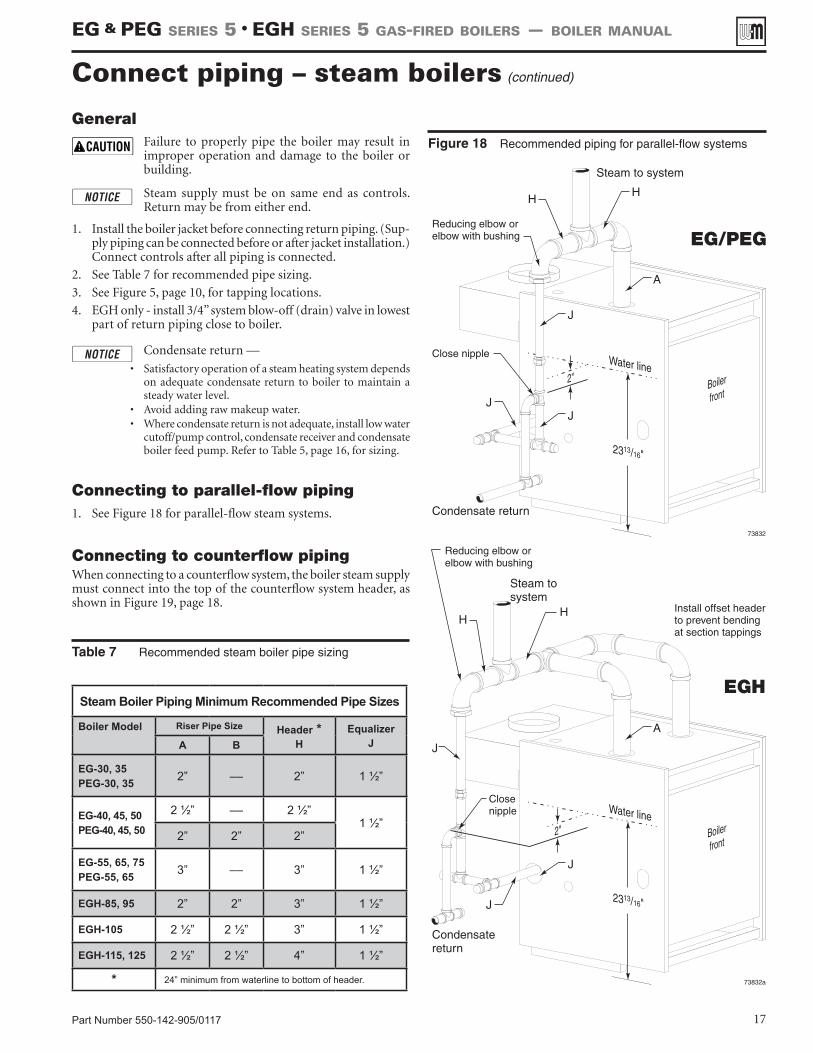
General Failure to properly pipe the boiler may result in
improper operation and damage to the boiler or building.
Steam supply must be on same end as controls. Return may be from either end.
1. Install the boiler jacket before connecting return piping. (Sup-ply piping can be connected before or after jacket installation.) Connect controls after all piping is connected.
2. See Table 7 for recommended pipe sizing.
3. See Figure 5, page 10, for tapping locations.
4. EGH only - install 3/4” system blow-off (drain) valve in lowest part of return piping close to boiler.
Condensate return —
• Satisfactory operation of a steam heating system depends on adequate condensate return to boiler to maintain a steady water level.
• Avoid adding raw makeup water.• Where condensate return is not adequate, install low water
cutoff/pump control, condensate receiver and condensate boiler feed pump. Refer to Table 5, page 16, for sizing.
Connecting to parallel-flow piping1. See Figure 18 for parallel-flow steam systems.
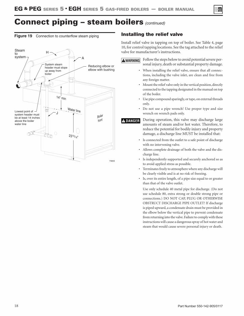
Connecting to counterflow pipingWhen connecting to a counterflow system, the boiler steam supply must connect into the top of the counterflow system header, as shown in Figure 19, page 18.
Figure 18 Recommended piping for parallel-flow systems
Table 7 Recommended steam boiler pipe sizing
Steam Boiler Piping Minimum Recommended Pipe Sizes
Boiler Model Riser Pipe Size Header *H
Equalizer JA B
EG-30, 35 PEG-30, 35 2” –– 2” 1 ½”
EG-40, 45, 50 PEG-40, 45, 50
2 ½” –– 2 ½”1 ½”
2” 2” 2”
EG-55, 65, 75 PEG-55, 65 3” –– 3” 1 ½”
EGH-85, 95 2” 2” 3” 1 ½”
EGH-105 2 ½” 2 ½” 3” 1 ½”
EGH-115, 125 2 ½” 2 ½” 4” 1 ½”
* 24” minimum from waterline to bottom of header.
Connect piping – steam boilers (continued)
EG & PEG sEriEs 5 • EGH sEriEs 5 Gas-firEd boilErs — boilEr manual
Part Number 550-142-905/011718
Installing the relief valve
Install relief valve in tapping on top of boiler. See Table 4, page 10, for control tapping locations. See the tag attached to the relief valve for manufacturer’s instructions.
Follow the steps below to avoid potential severe per-sonal injury, death or substantial property damage.
• When installing the relief valve, ensure that all connec-tions, including the valve inlet, are clean and free from any foreign matter.
• Mount the relief valve only in the vertical position, directly connected to the tapping designated in the manual on top of the boiler.
• Use pipe compound sparingly, or tape, on external threads only.
• Do not use a pipe wrench! Use proper type and size wrench on wrench pads only.
During operation, this valve may discharge large amounts of steam and/or hot water. Therefore, to reduce the potential for bodily injury and property damage, a discharge line MUST be installed that:
• Is connected from the outlet to a safe point of discharge with no intervening valve.
• Allows complete drainage of both the valve and the dis-charge line.
• Is independently supported and securely anchored so as to avoid applied stress as possible.
• Terminates freely to atmosphere where any discharge will be clearly visible and is at no risk of freezing.
• Is, over its entire length, of a pipe size equal to or greater than that of the valve outlet.
Use only schedule 40 metal pipe for discharge. (Do not use schedule 80, extra strong or double strong pipe or connections.) DO NOT CAP, PLUG OR OTHERWISE OBSTRUCT DISCHARGE PIPE OUTLET! If discharge is piped upward, a condensate drain must be provided in the elbow below the vertical pipe to prevent condensate from returning into the valve. Failure to comply with these instructions will cause a dangerous spray of hot water and steam that would cause severe personal injury or death.
Figure 19 Connection to counterflow steam piping
Connect piping – steam boilers (continued)
EG & PEG sEriEs 5 • EGH sEriEs 5 Gas-firEd boilErs — boilEr manual
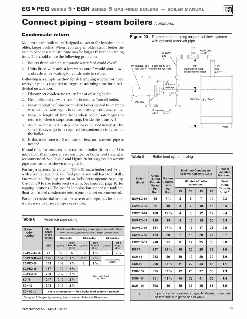
Table 9 Boiler feed system sizing
Figure 20 Recommended piping for parallel-flow systems with optional reservoir pipe
Part Number 550-142-905/0117 19
Condensate return
Modern steam boilers are designed to steam for less time than older, larger boilers. When replacing an older steam boiler the system condensate return time may be longer than the steaming time. This could cause the following problems:
1. Boilers fitted with an automatic water feed could overfill.
2. Units fitted with only a low water cutoff would shut down and cycle while waiting for condensate to return.
Following is a simple method for determining whether or not a reservoir pipe is required to lengthen steaming time for a resi-dential installation:
1. Disconnect condensate return line at existing boiler.
2. Heat boiler and allow to steam for 10 minutes. Turn off boiler.
3. Measure length of time from when boiler started to steam to when condensate begins to return through condensate line.
4. Measure length of time from when condensate begins to return to when it stops returning. Divide this time by 2.
5. Add time measured in step 3 to time calculated in step 4. This sum is the average time required for condensate to return to the boiler.
6. If this total time is 10 minutes or less, no reservoir pipe is needed.
If total time for condensate to return to boiler (from step 5) is more than 10 minutes, a reservoir pipe (or boiler feed system) is recommended. See Table 8 and Figure 20 for suggested reservoir pipe size. Install as shown in Figure 20.
For larger systems (as noted in Table 8), use a boiler feed system with a condensate tank and feed pump. You will have to install a low water cutoff/pump control on the boiler to operate the pump. Use Table 9 to size boiler feed systems. See Figure 5, page 10, for tapping locations. (The use of a combination condensate tank and float-controlled condensate return pump is not recommended.)
For most residential installations a reservoir pipe may be all that is necessary to ensure proper operation.
Boiler model number
Max. boiler grossoutput
Time from initial steaming to average condensate return(boiler steaming capacity based on 970 Btu per pound of steam)
15 minutes 20 minutes 30 minutes
MBH gallonspipe
length (feet)
gallonspipe
length (feet)
gallonspipe
length (feet)
EG/PEG-30,-35 75 ¾ ¾ 1 ½ 1 ½ 3 2 ½EG/PEG-40,-45 125 1 ¼ 1 ¼ 2 ½ 2 ¼ Use boiler feed
systemEG/PEG-50 145 1 ½ 1 ½ 3 2 ½EG/PEG-55 167 1 ¾ 1 ¾
Use boiler feedsystem
EG/PEG-65 209 2 ¼ 2 ¼EG-75 247 2 ½ 2 ½
EGH-85 243 2 ½ 2 ½
EGH-95 up Not recommended –– Use boiler feed system if needed
Designed full capacity steaming time of modern boilers is 10 minutes.
Table 8 Reservoir pipe sizing
BoilerModel
Gross Output Pounds Steam
PerHour
GallonsConden-
sate Per
Hour
Minimum Condensate Receiver Capacity (Gal.)
Recom-mended
Maximum
Minutes of boiler operation:
FeedPump
Capacity GPM *15 30 45 60
EG/PEG-30 65 7 ½ 2 5 7 10 0.3
EG/PEG-35 86 10 3 7 10 13 0.3
EG/PEG-40 108 12 ½ 4 8 12 17 0.4
EG/PEG-45 130 15 5 10 15 20 0.5
EG/PEG-50 151 17 ½ 6 12 17 23 0.6
EG/PEG-55 174 20 7 13 20 27 0.7
EG/PEG-65 218 25 8 17 25 33 0.8
EG-75 257 29 ½ 10 20 29 39 1.0
EGH-85 253 29 10 19 29 39 1.0
EGH-95 290 33 ½ 11 22 33 45 1.1
EGH-105 325 37 ½ 12 25 37 50 1.3
EGH-115 361 41 ½ 14 28 41 55 1.4
EGH-125 398 46 15 31 45 61 1.5
* If pump capacity exceeds capacity shown, pump can be throttled with globe or ball valve.
Connect piping – steam boilers (continued)
EG & PEG sEriEs 5 • EGH sEriEs 5 Gas-firEd boilErs — boilEr manual
Part Number 550-142-905/011720
Failure to properly install, pipe and wire boiler controls may result in severe damage to the boiler, building and personnel.
Water boiler - EG only
1. Install controls as shown on Control Tapping Table and Figure 5, page 10.
2. Low water cut off for water boilers:
a) Must be installed if boiler is located above radiation level.
b) May be required on water boilers by certain state, lo-
cal or territorial codes or insurance companies. If
a low water cut-off is used on a water boiler, use a
control designed especially for water installations.
An electrode probe type may be located in a tee in the
supply line above boiler, also see Table 4, page 10.
3. If system is to be ASME inspected and approved, an ad-ditional high temperature limit is needed. Purchase and install in supply line above boiler.
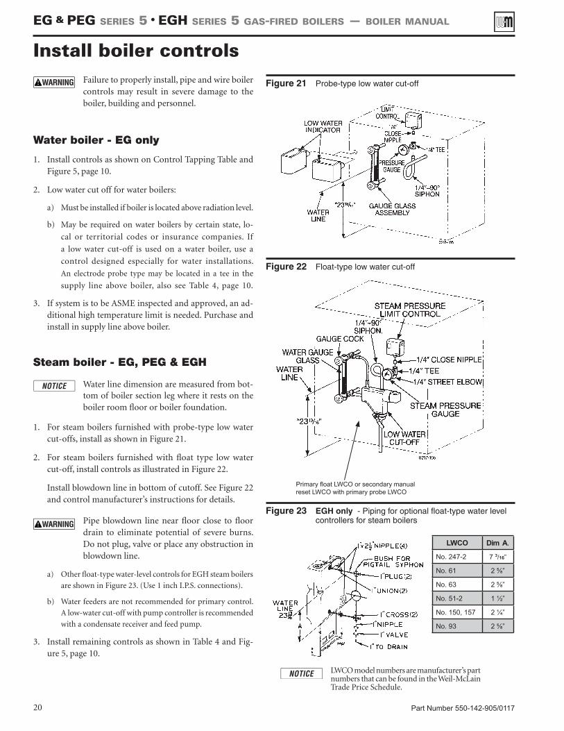
Steam boiler - EG, PEG & EGH
Water line dimension are measured from bot-tom of boiler section leg where it rests on the boiler room floor or boiler foundation.
1. For steam boilers furnished with probe-type low water cut-offs, install as shown in Figure 21.
2. For steam boilers furnished with float type low water cut-off, install controls as illustrated in Figure 22.
Install blowdown line in bottom of cutoff. See Figure 22 and control manufacturer’s instructions for details.
Pipe blowdown line near floor close to floor drain to eliminate potential of severe burns. Do not plug, valve or place any obstruction in blowdown line.
a) Other float-type water-level controls for EGH steam boilers
are shown in Figure 23. (Use 1 inch I.P.S. connections).
b) Water feeders are not recommended for primary control.
A low-water cut-off with pump controller is recommended
with a condensate receiver and feed pump.
3. Install remaining controls as shown in Table 4 and Fig-ure 5, page 10.
Install boiler controls
Figure 23 EGH only - Piping for optional float-type water level controllers for steam boilers
LWCO model numbers are manufacturer’s part numbers that can be found in the Weil-McLain Trade Price Schedule.
LWCO Dim A.
No. 247-2 7 ³/16”
No. 61 2 ⅝”
No. 63 2 ⅝”
No. 51-2 1 ½”
No. 150, 157 2 ¼”
No. 93 2 ⅝”
Primary float LWCO or secondary manual reset LWCO with primary probe LWCO
EG & PEG sEriEs 5 • EGH sEriEs 5 Gas-firEd boilErs — boilEr manual
Figure 21 Probe-type low water cut-off
Figure 22 Float-type low water cut-off
Part Number 550-142-905/0117 21
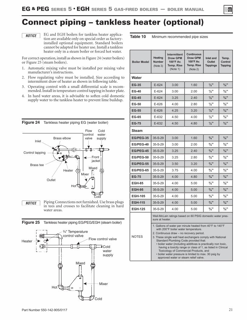
EG and EGH boilers for tankless heater applica-tion are available only on special order as factory-installed optional equipment. Standard boilers cannot be adapted for heater use. Install a tankless heater only in a steam boiler or forced hot water.
For correct operation, install as shown in Figure 24 (water boilers) or Figure 25 (steam boilers).
1. Automatic mixing valve must be installed per mixing valve manufacturer’s instructions.
2. Flow regulating valve must be installed. Size according to intermittent draw of heater as shown in following table.
3. Operating control with a small differential scale is recom-mended. Install in temperature control tapping in heater plate.
4. In hard water areas, it is advisable to soften cold domestic supply water to the tankless heater to prevent lime buildup.
Figure 24 Tankless heater piping EG (water boiler)
Connect piping – tankless heater (optional)Table 10 Minimum recommended pipe sizes
Piping Connections not furnished. Use brass plugs in tees and crosses to facilitate cleaning in hard water areas.
Figure 25 Tankless heater piping EG/PEG/EGH (steam boiler)
Boiler Model Heating Number (Note 3)
Intermittent Draw GPM 100°F Av.
Temp. Rise (Note 1)
Continuous Draw GPM 100°F Av.
Temp. Rise (Note 2)
Inlet and Outlet
Tappings
Temp. Control Tapping
Water
EG-35 E-624 3.00 1.60 ½” ¾”EG-40 E-624 3.00 2.00 ½” ¾”EG-45 E-624 3.25 2.40 ½” ¾”EG-50 E-626 4.00 2.80 ½” ¾”EG-55 E-626 4.25 3.20 ½” ¾”EG-65 E-632 4.50 4.00 ½” ¾”EG-75 E-632 4.50 4.80 ½” ¾”
Steam
EG/PEG-35 35-S-29 3.00 1.60 ¾” ¾”EG/PEG-40 35-S-29 3.00 2.00 ¾” ¾”EG/PEG-45 35-S-29 3.25 2.40 ¾” ¾”EG/PEG-50 35-S-29 3.25 2.80 ¾” ¾”EG/PEG-55 35-S-29 3.50 3.20 ¾” ¾”EG/PEG-65 35-S-29 3.75 4.00 ¾” ¾”EG-75 35-S-29 4.00 4.80 ¾” ¾”EGH-85 35-S-29 4.00 5.00 ¾” ¾”EGH-95 35-S-29 4.00 5.00 ¾” ¾”EGH-105 35-S-29 4.00 5.00 ¾” ¾”EGH-115 35-S-29 4.00 5.00 ¾” ¾”EGH-125 35-S-29 4.00 5.00 ¾” ¾”
NOTES
Weil-McLain ratings based on 60 PSIG domestic water pres-sure at heater.
1. Gallons of water per minute heated from 40°F to 140°F with 200°F boiler water temperature.
2. Continuous draw – no recovery period. 3. These single wall heat exchangers comply with National
Standard Plumbing Code provided that: • boiler water (including additives is practically non toxic, having a toxicity range or class of 1, as listed in Clinical Toxicology of Commercial Products, and • boiler water pressure is limited to max. 30 psig by approved water or steam relief valve.
EG & PEG sEriEs 5 • EGH sEriEs 5 Gas-firEd boilErs — boilEr manual
Part Number 550-142-905/011722
Connecting gas supply piping
1. Size gas piping considering:a) Diameter and length of gas supplying piping.b) Number of fittings.c) Maximum gas consumption (including any possible future
expansion).d) Allowable loss in gas pressure from gas meter outlet to boiler.
For pressure drops, see ANSI Z223.1/NFPA 54. Canadian instal-lations must comply with Natural Gas and Propane Installation Code, CAN/CSA B149.1 or B149.2 Installation Codes.
2. For natural gas:a) Refer to Table 11 or the National Fuel Gas Code. To obtain cubic
feet per hour, divide the input by 1000.b) Size for rated boiler input.c) Inlet gas pressure: 5” w.c. minimum 13” w.c. maximumd) Manifold gas pressure: 3Z\₂" w.c.e) Install 100% lock-up gas pressure regulator in supply line if inlet
pressure exceeds 13" w.c., then adjust for 13" w.c. maximum.
3. For propane gas:a) Inlet gas pressure: 11” w.c. minimum 13” w.c. maximumb) Manifold gas pressure: 10” w.c.c) Gas pressure regulator provided by gas supplier must be adjusted
for maximum pressure of 13” w.c.d) Contact gas supplier to size pipes, tanks and regulator.
4. Remove knock-out disc from jacket panel which gas supply is to be piped.
5. Follow good piping practices.
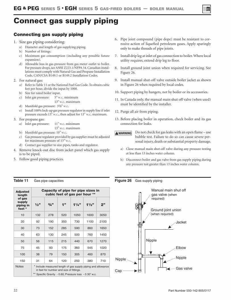
6. Pipe joint compound (pipe dope) must be resistant to cor-rosive action of liquefied petroleum gases. Apply sparingly only to make threads of pipe joints.
7. Install drip leg at inlet of gas connection to boiler. Where local utility requires, extend drip leg to floor.
8. Install ground joint union when required for servicing. See Figure 26.
9. Install manual shut-off valve outside boiler jacket as shown in Figure 26 when required by local codes.
10. Support piping by hangers, not by boiler or its accessories.
11. In Canada only, the manual main shut off valve (when used) must be identified by the installer.
12. Purge all air from piping.
13. Before placing boiler in operation, check boiler and its gas connection for leaks.
Do not check for gas leaks with an open flame – use bubble test. Failure to do so can cause severe per-sonal injury, death or substantial property damage.
a) Close manual main shut-off valve during any pressure testing at less than 13 inches water column.
b) Disconnect boiler and gas valve from gas supply piping during any pressure test greater than 13 inches water column.
Figure 26 Gas supply piping
Connect gas supply piping
Table 11 Gas pipe capacities
Adjustedlengthof gassupply
piping in feet *
Capacity of pipe for pipe sizes incubic feet of gas per hour **
½” ¾” 1” 1¼” 1½” 2”
10 132 278 520 1050 1600 3050
20 92 190 350 730 1100 2100
30 73 152 285 590 860 1650
40 63 130 245 500 760 1450
50 56 115 215 440 670 1270
75 45 93 175 360 545 1020
100 38 79 150 305 460 870
150 31 64 120 250 380 710
Notes * Include measured length of gas supply piping and allowance in feet for number and size of fittings.
** Specific Gravity - 0.60; Pressure loss - 0.30” w.c.
EG & PEG sEriEs 5 • EGH sEriEs 5 Gas-firEd boilErs — boilEr manual
Part Number 550-142-905/0117 23
For your safety, turn off electrical power supply at ser-vice entrance panel before making any electrical con-nections to avoid possible electric shock hazard. Fail-ure to do so can cause severe personal injury or death.
Refer to the Control Supplement for additional information, operating instructions and control wiring diagram.
Wiring must be N.E.C. Class 1.
If rollout thermal fuse element wire supplied with boiler must be replaced, type 200 °C wire or equiva-lent must be used. If other original wiring supplied with boiler must be replaced, use only type 105 °C wire or equivalent.
Boiler must be electrically grounded as required by National Electrical Code ANSI/NFPA 70–latest edition.
Electrical installation must comply with:1. National Electrical Code and any other national, state, pro-
vincial or local codes or regulations.2. In Canada, CSA C22.1 Canadian Electrical Code Part 1, and
any local codes
Wiring connections1. Boiler is shipped with controls completely wired, except
spill switch and vent damper. See wiring diagram in Control Supplement for details.
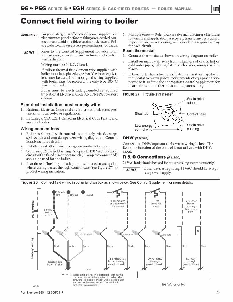
2. Installer must attach wiring diagram inside jacket door.3. See Figure 26 for field wiring. A separate 120 VAC electrical
circuit with a fused disconnect switch (15 amp recommended) should be used for the boiler.
4. A strain relief bushing and adapter must be used at each point where wiring passes through control case (see Figure 27) to protect wiring insulation.
5. Multiple zones — Refer to zone valve manufacturer’s literature for wiring and application. A separate transformer is required to power zone valves. Zoning with circulators requires a relay for each circuit.
Room thermostat1. Connect thermostat as shown on wiring diagram on boiler.
2. Install on inside wall away from influences of drafts, hot or cold water pipes, lighting fixtures, television, sunrays or fire-places.
3. If thermostat has a heat anticipator, set heat anticipator in thermostat to match power requirements of equipment con-nected to it. Refer to the appropriate Control Supplement for instructions on the thermostat anticipator setting.
Figure 27 Provide strain relief
Connect field wiring to boiler
Figure 26 Connect field wiring in boiler junction box as shown below. See Control Supplement for more details.
DHW (if used) Connect the DHW aquastat as shown in wiring below. The Economy function of the control is not utilized with DHW input.
R & C Connections (if used) 24 VAC leads should be used for power stealing thermostats only !
Other devices requiring 24 VAC should have sepa-rate power supply.
EG & PEG sEriEs 5 • EGH sEriEs 5 Gas-firEd boilErs — boilEr manual
Part Number 550-142-905/011724
Freeze protection (when used)Use antifreeze especially made for hydronic systems. Inhibited propylene glycol is recommended.
Do not use automotive, ethylene glycol or undiluted antifreeze. Severe personal injury, death or substan-tial property damage can result.
A 50% glycol solution provides protection to about -30°F.
Local codes may require back-flow preventer or actual disconnect from city water supply.
Determine quantity according to system water content. Boiler water content is listed on page 38. Remember to add in expansion tank water content.
Follow antifreeze manufacturer’s instructions.
Filling water systems
1. Close manual air vents, drain cock, and automatic air vent, if used.
2. Fill to correct system pressure. Correct pressure will vary with each application. Residential systems are often designed for 12 psig of cold fill pressure.
3. Open automatic air vent one turn, if used.
4. Open manual water feed valve.
a) Starting on lowest floor, open air vents one at a time until water squirts out. Close vent.
b) Repeat with remaining vents.
5. Close manual water feed valve when correct boiler pressure is reached.
6. If purge valve is used - located in the return piping above isolation valve:
a) Connect hose to purge valve.b) Close isolation valve. Open purge valve.c) Open hand water feed valve and allow system to purge all
air. If system has more than one circuit, purge each circuit separately by opening each balancing valve one at a time.
d) Close purge valve and water feed valve cock. e) Open isolation valve.f) Fill system to correct pressure.
Filling steam boilers1. Fill to normal waterline, halfway up gauge glass.
2. Boiler water pH 7.0 to 8.5 is recommended.
3. Follow skimming procedure.
Wiring multiple zones Refer to zone valve manufacturer’s literature for wiring and ap-plication. A separate transformer is required to power zone valves. Zoning with circulators requires a relay for each circulator.
DO NOT connect directly from 3-wire zone valves to the T-T terminals on the boiler. When using 3-wire zone valves, install an isolation relay. Connect the zone valve end switch wires to the isolation relay coil. Connect the isolation relay contact across the boiler T-T terminals. Failure to comply can result in damage to boiler components or cause unreliable operation, resulting in severe property damage.
Check for gas leaks Before starting the boiler, and during initial opera-
tion, smell near the floor and around the boiler for gas odorant or any unusual odor. Do not proceed with start-up if there is any indication of a gas leak. Repair any leak at once.
Propane boilers only — Your propane supplier mixes an odorant with the propane to make its presence detectable. In some instances, the odorant can fade and the gas may no longer have an odor.
• Propane gas can accumulate at floor level. Smell near the floor for the gas odorant or any unusual odor. If you suspect a leak, do not attempt to light the pilot.
• Use caution when attempting to light the propane pilot. This should be done by a qualified service technician, particularly if pilot outages are common.
• Periodically check the odorant level of your gas.• Inspect boiler and system at least yearly to make
sure all gas piping is leak-tight.• Consult your propane supplier regarding installa-
tion of a gas leak detector. There are some products on the market intended for this purpose. Your sup-plier may be able to suggest an appropriate device.
Fill the system Do not fill (except for leakage tests) until the boiler
is ready to be fired.
Determine if water treatment is needed
Do not use petroleum-based cleaning or sealing compounds in boiler system. Severe damage to boiler will occur, resulting in substantial property damage.
Eliminate all system leaks. Continual fresh makeup water will reduce boiler life. Minerals can build up in sections, reducing heat transfer, overheating cast iron, and causing section failure.
Consult local water treatment companies for unusually hard water areas (above 7 grains hardness) or low pH water conditions (below 7.0). Boiler water pH of 7.0 to 8.5 is recommended.
Start-up
EG & PEG sEriEs 5 • EGH sEriEs 5 Gas-firEd boilErs — boilEr manual
Part Number 550-142-905/0117 25
Operate boiler
Check system and boiler
DO NOT proceed with boiler operation unless boiler and system have been filled with water and all instructions and procedures of previous manual sections have been completed. Failure to do so could result in severe personal injury, death or substantial property damage.
Before starting the boiler . . .• See Control Supplement for “Operating Instruc-
tions”.• Verify the boiler and system water level is correct
(Steam — no more than ½ of gauge glass or less than ¼” above bottom of gauge glass).
• Verify the “Preparation” procedures on the previous pages have been completed.
Start the boiler1. Steam boilers — Check boiler water level — Should be ap-
proximately ½ way up gauge glass.
2. Remove boiler jacket door and note the gas valve manufacturer and model number.
3. Follow the Lighting or Operating Instructions in the Control Supplement, depending on gas valve installed in boiler. Use only the Operating Instruction which applies to this gas valve. (The Operating Instruction label on the boiler provides the same information.)
4. If boiler fails to start, see “If boiler doesn’t start . . . Check for:” on the next page.
Check system and boiler
Eliminate all system leaks. Continual fresh makeup water will reduce boiler life. Minerals can build up in sections, reducing heat transfer, overheating cast iron, and causing section failure.
If you discover evidence of any gas leak, shut down the boiler at once. Find the leak source with bubble test and repair immediately. Do not start boiler again until corrected. Failure to comply could re-sult in severe personal injury, death or substantial property damage.
Do not use petroleum-based cleaning or sealing compounds in boiler system. Severe damage to boiler will occur, resulting in substantial property damage.
1. Check system piping for leaks. If found, shut down boiler and repair immediately.
2. Inspect vent system thoroughly for signs of deterioration from corrosion, physical damage or sagging. Verify that masonry chimney liners are in good condition, with no obstructions, and there are no openings into the chimney.
3. Check around the boiler for gas leaks following the procedure of step 13, page 22.
4. Verify operation using procedures below. Perform “Checkout procedure”, page 27, and fill in the “Installation and Service Certificate”.
Skim the steam boiler
Clean all newly installed steam boilers to remove oil and grease. Failure to properly clean can result in violent fluctuations of water level, water passing into steam mains or high maintenance costs on strainers, traps and vents.
Do not use petroleum-based cleaning or sealing compounds in boiler system. Severe damage to boiler will occur, resulting in substantial property damage.
1. Provide 1½” piping from skim tapping to floor drain.
2. Adjust waterline to midpoint of skim tapping. See Figure 5, page 10.
3. Follow “Operating Instructions” in the Control Supplement to fire boiler to maintain temperature below steaming rate.
4. Feed in water to maintain water level. Cycle burners to prevent rise in steam pressure.
5. Continue skimming until discharge is clear. May take several hours.
6. Drain boiler. While boiler is warm, but not hot, flush all inte-rior surfaces under full pressure until drain water runs clear.
7. Remove skim piping. Plug tapping.
8. Close drain cock. Fill with fresh water to waterline. Start burn-ers and steam for 15 minutes to remove dissolved gases. Stop burners.
9. Check traps and air vents for proper operation.
10. Process may need to be repeated after several weeks of opera-tion.
Inspect base insulation The boiler contains ceramic fiber and fiberglass
materials. Use care when handling these materials per instructions on page 33 of this manual. Failure to comply could result in severe personal injury.
Check to make sure insulation is secure against all four sides of the base. If insulation is damaged or displaced, do not operate boiler. Replace or reposition insulation.
Failure to replace damaged insulation or reposition insulation can result in a fire hazard, causing se-vere personal injury, death or substantial property damage.
Start-up (continued)
EG & PEG sEriEs 5 • EGH sEriEs 5 Gas-firEd boilErs — boilEr manual
Part Number 550-142-905/011726
4. Repeat Steps 2 through 4 several times to verify operation.
5. Return thermostat to normal setting.
6. Set thermostat heat anticipator setting indicated on wiring diagram.
Check venting system operationWith boiler firing, hold a candle or match below lower edge of draft diverter “skirt.” If flame does not blow out, but burns undis-turbed, the vent system is working properly. If flame blows out or flickers severely, the vent system must be checked for obstructions or other causes of improper venting.
Verify operation
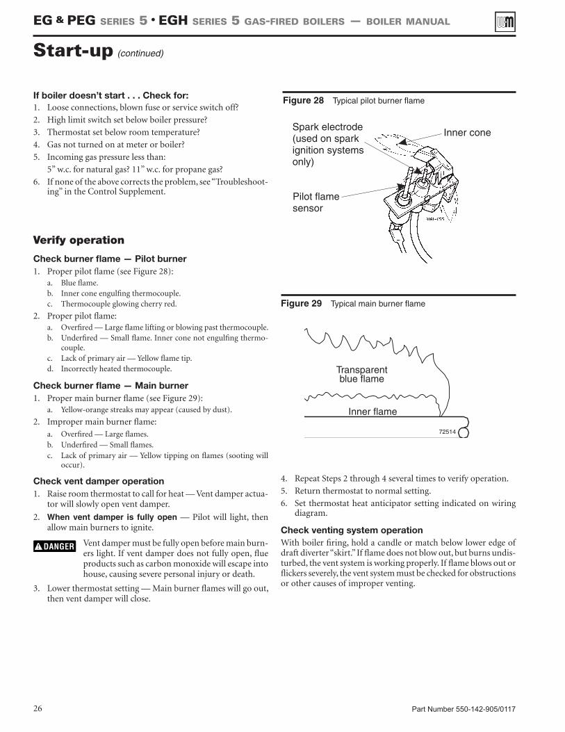
Check burner flame — Pilot burner 1. Proper pilot flame (see Figure 28):
a. Blue flame.b. Inner cone engulfing thermocouple.c. Thermocouple glowing cherry red.
2. Proper pilot flame:a. Overfired — Large flame lifting or blowing past thermocouple.b. Underfired — Small flame. Inner cone not engulfing thermo-
couple.c. Lack of primary air — Yellow flame tip.d. Incorrectly heated thermocouple.
Check burner flame — Main burner 1. Proper main burner flame (see Figure 29):
a. Yellow-orange streaks may appear (caused by dust).
2. Improper main burner flame:a. Overfired — Large flames.b. Underfired — Small flames.c. Lack of primary air — Yellow tipping on flames (sooting will
occur).
Check vent damper operation1. Raise room thermostat to call for heat — Vent damper actua-
tor will slowly open vent damper.
2. When vent damper is fully open — Pilot will light, then allow main burners to ignite.
Vent damper must be fully open before main burn-ers light. If vent damper does not fully open, flue products such as carbon monoxide will escape into house, causing severe personal injury or death.
3. Lower thermostat setting — Main burner flames will go out, then vent damper will close.
Start-up (continued)
If boiler doesn’t start . . . Check for:1. Loose connections, blown fuse or service switch off?
2. High limit switch set below boiler pressure?
3. Thermostat set below room temperature?
4. Gas not turned on at meter or boiler?
5. Incoming gas pressure less than:
5” w.c. for natural gas? 11” w.c. for propane gas?
6. If none of the above corrects the problem, see “Troubleshoot-ing” in the Control Supplement.
Figure 28 Typical pilot burner flame
Figure 29 Typical main burner flame
EG & PEG sEriEs 5 • EGH sEriEs 5 Gas-firEd boilErs — boilEr manual
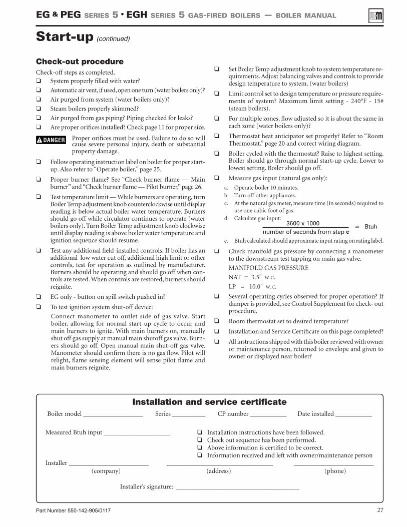
Part Number 550-142-905/0117 27
Check-out procedureCheck-off steps as completed.❏ System properly filled with water?
❏ Automatic air vent, if used, open one turn (water boilers only)?
❏ Air purged from system (water boilers only)?
❏ Steam boilers properly skimmed?
❏ Air purged from gas piping? Piping checked for leaks?
❏ Are proper orifices installed? Check page 11 for proper size.
Proper orifices must be used. Failure to do so will cause severe personal injury, death or substantial property damage.
❏ Follow operating instruction label on boiler for proper start-up. Also refer to “Operate boiler,” page 25.
❏ Proper burner flame? See “Check burner flame — Main burner” and “Check burner flame — Pilot burner,” page 26.
❏ Test temperature limit — While burners are operating, turn Boiler Temp adjustment knob counterclockwise until display reading is below actual boiler water temperature. Burners should go off while circulator continues to operate (water boilers only). Turn Boiler Temp adjustment knob clockwise until display reading is above boiler water temperature and ignition sequence should resume.
❏ Test any additional field-installed controls: If boiler has an additional low water cut off, additional high limit or other controls, test for operation as outlined by manufacturer. Burners should be operating and should go off when con-trols are tested. When controls are restored, burners should reignite.
❏ EG only - button on spill switch pushed in?
❏ To test ignition system shut-off device:
Connect manometer to outlet side of gas valve. Start boiler, allowing for normal start-up cycle to occur and main burners to ignite. With main burners on, manually shut off gas supply at manual main shutoff gas valve. Burn-ers should go off. Open manual main shut-off gas valve. Manometer should confirm there is no gas flow. Pilot will relight, flame sensing element will sense pilot flame and main burners reignite.
❏ Set Boiler Temp adjustment knob to system temperature re-quirements. Adjust balancing valves and controls to provide design temperature to system. (water boilers)
❏ Limit control set to design temperature or pressure require-ments of system? Maximum limit setting - 240°F - 15# (steam boilers).
❏ For multiple zones, flow adjusted so it is about the same in each zone (water boilers only)?
❏ Thermostat heat anticipator set properly? Refer to “Room Thermostat,” page 20 and correct wiring diagram.
❏ Boiler cycled with the thermostat? Raise to highest setting. Boiler should go through normal start-up cycle. Lower to lowest setting. Boiler should go off.
❏ Measure gas input (natural gas only):
a. Operate boiler 10 minutes.b. Turn off other appliances.c. At the natural gas meter, measure time (in seconds) required to
use one cubic foot of gas.d. Calculate gas input:
3600 x 1000number of seconds from step c
= Btuh
e. Btuh calculated should approximate input rating on rating label.
❏ Check manifold gas pressure by connecting a manometer to the downstream test tapping on main gas valve.
MANIFOLD GAS PRESSURE
NAT = 3.5" w.c.
LP = 10.0" w.c.
❏ Several operating cycles observed for proper operation? If damper is provided, see Control Supplement for check- out procedure.
❏ Room thermostat set to desired temperature?
❏ Installation and Service Certificate on this page completed?
❏ All instructions shipped with this boiler reviewed with owner or maintenance person, returned to envelope and given to owner or displayed near boiler?
Start-up (continued)
Installation and service certificateBoiler model __________________ Series __________ CP number ___________ Date installed ___________
Measured Btuh input ____________________
Installer ________________________ ________________________________ ________________________ (company) (address) (phone)
Installer’s signature: _____________________________________
❏ Installation instructions have been followed.❏ Check out sequence has been performed.❏ Above information is certified to be correct.❏ Information received and left with owner/maintenance person
EG & PEG sEriEs 5 • EGH sEriEs 5 Gas-firEd boilErs — boilEr manual
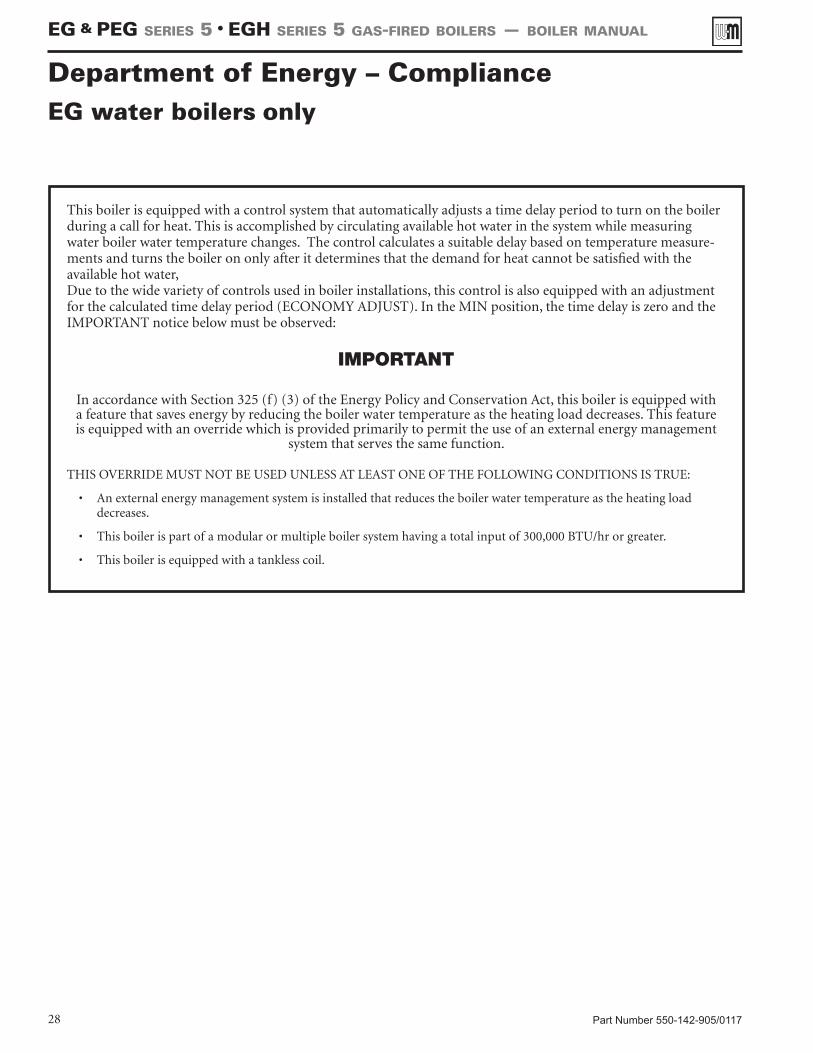
Part Number 550-142-905/011728
Department of Energy – ComplianceEG water boilers only
This boiler is equipped with a control system that automatically adjusts a time delay period to turn on the boiler during a call for heat. This is accomplished by circulating available hot water in the system while measuring water boiler water temperature changes. The control calculates a suitable delay based on temperature measure-ments and turns the boiler on only after it determines that the demand for heat cannot be satisfied with the available hot water,Due to the wide variety of controls used in boiler installations, this control is also equipped with an adjustment for the calculated time delay period (ECONOMY ADJUST). In the MIN position, the time delay is zero and the IMPORTANT notice below must be observed:
IMPORTANT
In accordance with Section 325 (f) (3) of the Energy Policy and Conservation Act, this boiler is equipped with a feature that saves energy by reducing the boiler water temperature as the heating load decreases. This feature is equipped with an override which is provided primarily to permit the use of an external energy management
system that serves the same function.
THIS OVERRIDE MUST NOT BE USED UNLESS AT LEAST ONE OF THE FOLLOWING CONDITIONS IS TRUE:
• An external energy management system is installed that reduces the boiler water temperature as the heating load decreases.
• This boiler is part of a modular or multiple boiler system having a total input of 300,000 BTU/hr or greater.
• This boiler is equipped with a tankless coil.
EG & PEG sEriEs 5 • EGH sEriEs 5 Gas-firEd boilErs — boilEr manual
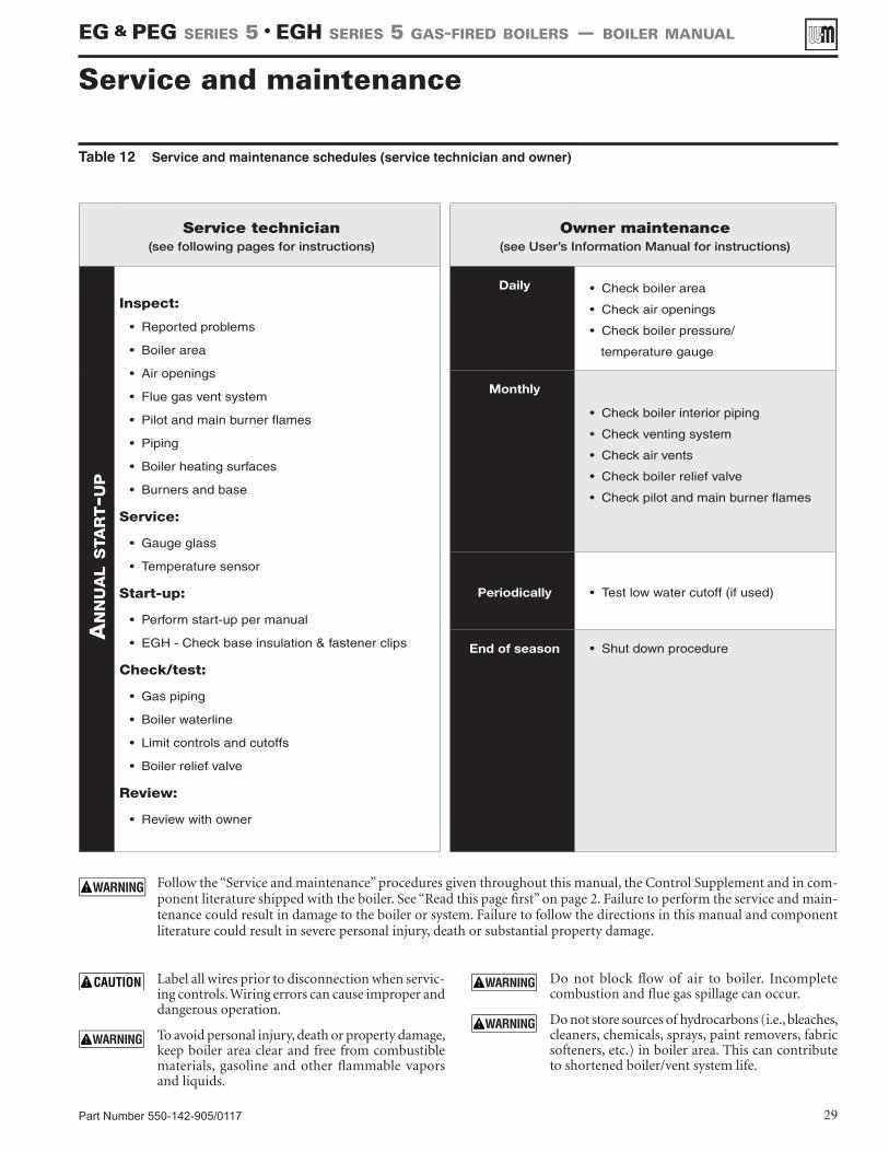
Part Number 550-142-905/0117 29
Table 12 Service and maintenance schedules (service technician and owner)
Follow the “Service and maintenance” procedures given throughout this manual, the Control Supplement and in com-ponent literature shipped with the boiler. See “Read this page first” on page 2. Failure to perform the service and main-tenance could result in damage to the boiler or system. Failure to follow the directions in this manual and component literature could result in severe personal injury, death or substantial property damage.
Service and maintenance
Label all wires prior to disconnection when servic-ing controls. Wiring errors can cause improper and dangerous operation.
To avoid personal injury, death or property damage, keep boiler area clear and free from combustible materials, gasoline and other flammable vapors and liquids.
Do not block flow of air to boiler. Incomplete combustion and flue gas spillage can occur.
Do not store sources of hydrocarbons (i.e., bleaches, cleaners, chemicals, sprays, paint removers, fabric softeners, etc.) in boiler area. This can contribute to shortened boiler/vent system life.
Service technician (see following pages for instructions)
Owner maintenance (see User’s Information Manual for instructions)
An
nu
Al s
tAr
t-u
p
Inspect:
• Reported problems
• Boiler area
• Air openings
• Flue gas vent system
• Pilot and main burner flames
• Piping
• Boiler heating surfaces
• Burners and base
Service:
• Gauge glass
• Temperature sensor
Start-up:
• Perform start-up per manual
• EGH - Check base insulation & fastener clips
Check/test:
• Gas piping
• Boiler waterline
• Limit controls and cutoffs
• Boiler relief valve
Review:
• Review with owner
Daily • Check boiler area
• Check air openings
• Check boiler pressure/
temperature gauge
Monthly
• Check boiler interior piping
• Check venting system
• Check air vents
• Check boiler relief valve
• Check pilot and main burner flames
Periodically • Test low water cutoff (if used)
End of season • Shut down procedure
EG & PEG sEriEs 5 • EGH sEriEs 5 Gas-firEd boilErs — boilEr manual
Part Number 550-142-905/011730
The boiler should be inspected and started annu-ally, at the beginning of the heating season, only by a qualified service technician. In addition, the maintenance and care of the boiler designated in Table 12, page 29 and explained on the following pages must be performed to assure maximum boiler efficiency and reliability. Failure to service and maintain the boiler and system could result in equipment failure.
Electrical shock hazard — Turn off power to the boiler before any service operation on the boiler except as noted otherwise in this manual. Failure to turn off electrical power could result in electrical shock, causing severe personal injury or death.
The boiler contains ceramic fiber and fiberglass materials. Use care when handling these materials per instructions on page 33 of this manual. Failure to comply could result in severe personal injury.
Inspect . . . . . . . . . .
Reported problemsInspect any problems reported by owner and correct before proceeding.
Boiler area1. Verify that boiler area is free of any combustible materials,
gasoline and other flammable vapors and liquids.
2. Verify that boiler area is free of any of the contaminants listed on page 7 of this manual. If any of these are present in the boiler intake air vicinity, they must be removed. If they can-not be removed, install combustion air piping to the boiler in accordance with national, provincial or local codes.
Air openings1. Verify that combustion and ventilation air openings to the
boiler room and/or building are open and unobstructed. Check operation and wiring of automatic combustion air dampers, if used.
2. Verify that boiler vent discharge and air intake are clean and free of obstructions.
Flue gas vent system1. Visually inspect entire flue gas venting system for blockage,
deterioration or leakage. Repair any joints that show signs of leakage in accordance with vent manufacturer’s instructions.
2. Verify that masonry chimneys are lined, lining is in good condition, and there are not openings into the chimney.
Failure to inspect for the above conditions and have them repaired can result in severe personal injury or death.
Pilot and main burner flamesVisually inspect pilot burner and main burner flames as directed on page 26 of this manual.
Piping1. Check the boiler interior piping and all system piping for signs
of leaks. Repair any leaks before proceeding.
Do not use petroleum-based cleaning or sealing compounds in boiler system. Severe damage to boiler will occur, resulting in substantial property damage.
Eliminate all system or boiler leaks. Continual fresh makeup water will reduce boiler life. Minerals can build up in sections, reducing heat transfer, overheating cast iron, and causing section failure. Leaking water may also cause severe property damage.
Boiler heating surfaces
The boiler contains ceramic fiber and fiberglass materials. Use care when handling these materials per instructions on page 33 of this manual. Failure to comply could result in severe personal injury.
1. Disconnect the vent pipe at the boiler draft diverter and re-move draft diverter after turning off power to the boiler.
2. Use a bright light to inspect the boiler flue collector and heat-ing surfaces.
3. If the vent pipe or boiler interior surfaces show evidence of soot, follow “Cleaning boiler heating surfaces”, page 30. Re-move the flue collector and clean the boiler if necessary after closer inspection of boiler heating surfaces.
4. If there is evidence of rusty scale deposits on boiler surfaces, check the water piping and control system to make sure the boiler return water temperature is properly maintained (per this manual).
5. Reconnect vent and draft diverter. Replace all boiler components before returning to service.
6. Check inside and around boiler for evidence of any leaks from the boiler. If found, locate source of leaks and repair.
Burners and base1. After turning off power to the boiler, remove the jacket door
and base access panel.
2. Inspect burners and all other components in the boiler base.
3. If burners must be cleaned, raise rear of each burner to release from support slot, slide forward and remove. Then brush and vacuum the burners thoroughly, making sure all ports are free of debris. Carefully replace all burners, making sure burner with pilot bracket is replaced in its original position and all burners are upright (ports up).
4. Inspect the base insulation.a. Verify that the insulation is intact and secure against all four
sides of the base and attachment clips are still in place.
If insulation is damaged or displaced, do not oper-ate the boiler. Replace or reposition insulation as necessary. Failure to replace damaged insulation can result in a fire hazard, causing severe personal injury, death or substantial property damage.
Service and maintenance (continued)
EG & PEG sEriEs 5 • EGH sEriEs 5 Gas-firEd boilErs — boilEr manual
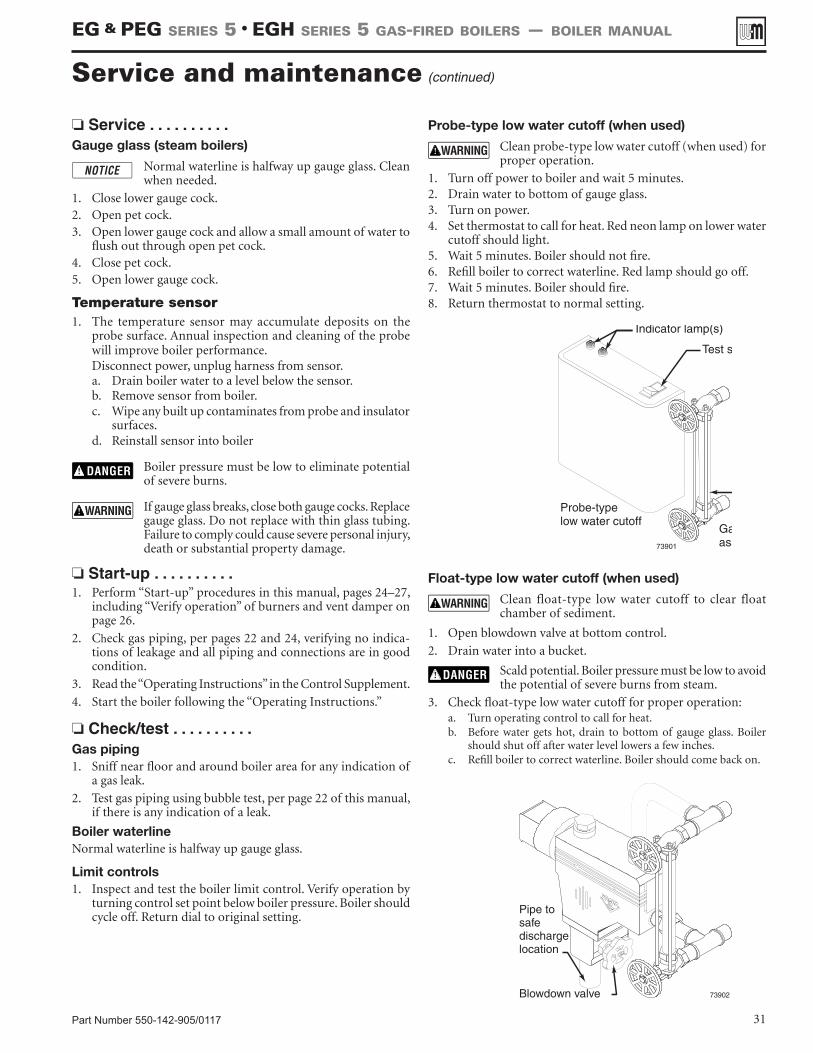
Part Number 550-142-905/0117 31
Service and maintenance (continued)
❏ Service . . . . . . . . . .Gauge glass (steam boilers)
Normal waterline is halfway up gauge glass. Clean when needed.
1. Close lower gauge cock.2. Open pet cock.3. Open lower gauge cock and allow a small amount of water to
flush out through open pet cock.4. Close pet cock.5. Open lower gauge cock.
Temperature sensor1. The temperature sensor may accumulate deposits on the
probe surface. Annual inspection and cleaning of the probe will improve boiler performance.Disconnect power, unplug harness from sensor.a. Drain boiler water to a level below the sensor.b. Remove sensor from boiler.c. Wipe any built up contaminates from probe and insulator
surfaces.d. Reinstall sensor into boiler
Boiler pressure must be low to eliminate potential of severe burns.
If gauge glass breaks, close both gauge cocks. Replace gauge glass. Do not replace with thin glass tubing. Failure to comply could cause severe personal injury, death or substantial property damage.
❏ Start-up . . . . . . . . . .1. Perform “Start-up” procedures in this manual, pages 24–27,
including “Verify operation” of burners and vent damper on page 26.
2. Check gas piping, per pages 22 and 24, verifying no indica-tions of leakage and all piping and connections are in good condition.
3. Read the “Operating Instructions” in the Control Supplement.
4. Start the boiler following the “Operating Instructions.”
❏ Check/test . . . . . . . . . .Gas piping 1. Sniff near floor and around boiler area for any indication of
a gas leak.
2. Test gas piping using bubble test, per page 22 of this manual, if there is any indication of a leak.
Boiler waterlineNormal waterline is halfway up gauge glass.
Limit controls 1. Inspect and test the boiler limit control. Verify operation by
turning control set point below boiler pressure. Boiler should cycle off. Return dial to original setting.
Probe-type low water cutoff (when used)
Clean probe-type low water cutoff (when used) for proper operation.
1. Turn off power to boiler and wait 5 minutes.2. Drain water to bottom of gauge glass.3. Turn on power.4. Set thermostat to call for heat. Red neon lamp on lower water
cutoff should light.5. Wait 5 minutes. Boiler should not fire.6. Refill boiler to correct waterline. Red lamp should go off.7. Wait 5 minutes. Boiler should fire.8. Return thermostat to normal setting.
Float-type low water cutoff (when used)
Clean float-type low water cutoff to clear float chamber of sediment.
1. Open blowdown valve at bottom control.
2. Drain water into a bucket.
Scald potential. Boiler pressure must be low to avoid the potential of severe burns from steam.
3. Check float-type low water cutoff for proper operation:a. Turn operating control to call for heat.b. Before water gets hot, drain to bottom of gauge glass. Boiler
should shut off after water level lowers a few inches.c. Refill boiler to correct waterline. Boiler should come back on.
EG & PEG sEriEs 5 • EGH sEriEs 5 Gas-firEd boilErs — boilEr manual
Part Number 550-142-905/011732
❏ Check/test . . . . . . . . . .
Boiler relief valve
1. After following the warning directions below, if the relief valve weeps or will not seat properly, replace the relief valve.
Before testing, make certain discharge pipe is proper-ly connected to valve outlet and arranged to contain and safely dispose of boiler discharge. Wear gloves to protect your hands from hot surfaces. Verify that discharge piping is installed in accordance with this manual and the instructions on the relief valve tag. Failure to comply will expose operator and others to severe personal injury or death.
Safety relief valves should be reinspected AT LEAST ONCE EVERY THREE YEARS, by a licensed plumb-ing contractor or authorized inspection agency, to ensure that the product has not been affected by corrosive water conditions and to ensure that the valve and discharge line have not been altered or tampered with illegally. Certain naturally occurring conditions may corrode the valve or its compo-nents over time, rendering the valve inoperative. Such conditions are not detectable unless the valve and its components are physically removed and inspected. This inspection must only be conducted by a plumbing contractor or authorized inspection agency — not by the owner. Failure to reinspect the boiler relief valve as directed could result in unsafe pressure buildup, which can result in severe personal injury, death or substantial property damage.
Check the setting of the boiler limit control. The control should never be set with a pressure above 10 psig. Operating at a higher pressure can cause damage to the boiler relief valve.
The boiler relief valve must be tested at least monthly during the heating season to verify the valve and discharge piping flow freely. If corrosion and/or deposits are noticed within the valve body, testing must be performed more often. A “try lever test” must also be performed at the end of any non-service period. Follow the instructions below for a “try lever test”:
With the system at operating pressure, lift and hold the test lever fully open for at least 5 seconds to flush the valve seat free of sediment and debris. Then release lever and permit the valve to snap shut.
❏ Review with owner1. Review the User’s Information Manual with the owner.
2. Emphasize the need to perform the maintenance schedule specified in the User’s Information Manual (and in this manual as well).
3. Remind the owner of the need to call in a licensed contractor should the boiler or system exhibit any unusual behavior.
4. Remind the owner to follow the proper shutdown procedure and to schedule an annual start-up at the beginning of the next heating season.
❏ Cleaning boiler heating surfaces The boiler contains ceramic fiber and fiberglass
materials. Use care when handling these materials per instructions on page 33 of this manual. Failure to comply could result in severe personal injury.
1. Follow shut-down procedure
2. Disconnect breeching and remove damper (if used) and draft hood.
3. Remove upper rear jacket panel. Turn back jacket insulation to expose collector hood.
4. Remove collector hood. Clean excess boiler cement from col-lector hood and cast iron sections.
5. Remove burners from base of boiler. Follow “Cleaning main burners” to thoroughly clean burners. Place newspaper in base of boiler to collect soot that will fall.
6. With a wire flue brush, clean between the sections.
7. Remove paper and soot. Vacuum or brush base and surround-ing area.
8. Replace collector hood. Seal with boiler cement.
9. Replace draft hood, damper (if used) and breeching.
10. Replace insulation and jacket panel.
11. Replace main burners.
Cleaning main burners1. Vacuum or brush burners to remove dust and lint.
When replacing, burner tubes must be seated in slots in the back with openings face up. Gas orifices must inject down center of burner. Failure to properly seat burners will result in severe personal injury, death or substantial property damage.
Annual shut-down procedure1. Follow correct operating instructions on boiler.
2. Do not drain system unless exposure to freezing temperatures will occur. If antifreeze is used with system, do not drain.
3. If complete boiler and piping system must be drained to avoid freezing, provide method to drain water from both ends of boiler at or below return tapping level.
Service and maintenance (continued)
EG & PEG sEriEs 5 • EGH sEriEs 5 Gas-firEd boilErs — boilEr manual
Part Number 550-142-905/0117 33
REMOVAL OF COMBUSTION CHAMBER LINING OR BASE PANELS
Handling fiberglass and ceramic fiber materials
The combustion chamber lining or base insulation panels in this product contains ceramic fiber materials that have been identified as carcinogenic, or possibly carcinogenic, to humans. Ceramic fibers can be converted to cristobalite in very high temperature applications. The International Agency for Research on Cancer (IARC) has concluded, “Crystalline silica inhaled in the form of quartz or cristobalite from occupational sources is carcinogenic to humans (Group 1).”:
■ Avoid breathing dust and contact with skin and eyes.• Use NIOSH certified dust respirator (N95). This type of respirator is based on the
OSHA requirements for cristobalite at the time this document was written. Other types of respirators may be needed depending on the job site conditions. Current NIOSH recommendations can be found on the NIOSH web site at http://www.cdc.gov/niosh/homepage.html. NIOSH approved respirators, manufacturers, and phone numbers are also listed on this web site.
• Wear long-sleeved, loose fitting clothing, gloves, and eye protection.■ Apply enough water to the combustion chamber lining or base insulation to prevent air-
borne dust.■ Remove combustion chamber lining or base insulation from the boiler and place it in a
plastic bag for disposal.■ Wash potentially contaminated clothes separately from other clothing. Rinse clothes washer
thoroughly.
NIOSH stated First Aid.■ Eye: Irrigate immediately.■ Breathing: Fresh air.
REMOVAL OF FIBERGLASS WOOL — OR —INSTALLATION OF FIBERGLASS WOOL, COMBUSTION CHAMBER LINING OR BASE PANELS:
This product contains fiberglass jacket insulation and ceramic fiber materials in combustion chamber lining or base panels in gas fired products. Airborne fibers from these materials have been listed by the State of California as a possible cause of cancer through inhalation.
■ Avoid breathing dust and contact with skin and eyes.
• Use NIOSH certified dust respirator (N95). This type of respirator is based on the OSHA requirements for fiberglass wool at the time this document was written. Other types of respirators may be needed depending on the job site conditions. Current NIOSH recommendations can be found on the NIOSH web site at http://www.cdc.gov/niosh/homepage.html. NIOSH approved respirators, manufacturers, and phone numbers are also listed on this web site.
• Wear long-sleeved, loose fitting clothing, gloves, and eye protection.
■ Operations such as sawing, blowing, tear out, and spraying may generate airborne fiber concentration requiring additional protection.
■ Wash potentially contaminated clothes separately from other clothing. Rinse clothes washer thoroughly.
NIOSH stated First Aid.■ Eye: Irrigate immediately.
■ Breathing: Fresh air.
EG & PEG sEriEs 5 • EGH sEriEs 5 Gas-firEd boilErs — boilEr manual
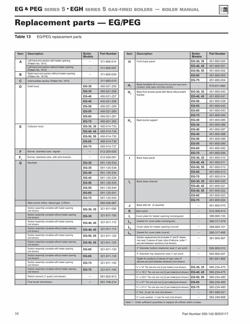
Part Number 550-142-905/011734
Replacement parts — EG/PEGTable 13 EG/PEG replacement parts
Item Description Boiler Models
Part Number
A Left hand end section with heater opening (Pattern No. 1814)
–– 311-800-014
Left hand end section without heater opening (Pattern No. 1813)
–– 311-800-007
B Right hand end section without heater opening (Pattern No. 18118)
–– 311-800-029
C Intermediate section (Pattern No. 1815) –– 311-800-010
D Draft hood EG-30 450-021-255
EG-35 450-021-256
EG-40 450-021-257
EG-45 450-021-258
EG-50 450-021-259
EG-55 450-021-260
EG-65 450-021-261
EG-75 450-021-262
E Collector hood EG-30, 35 450-014-733
EG-40, 45 450-014-734
EG-50, 55 450-014-735
EG-65 450-014-736
EG-75 450-014-737
F Burner, stainless tube, regular –– 512-200-000
F1Burner, stainless tube, with pilot bracket –– 512-200-001
G Manifold EG-30 591-125-533
EG-35 591-125-538
EG-40 591-125-534
EG-45 591-125-539
EG-50 591-125-535
EG-55 591-125-540
EG-65 591-125-541
EG-75 591-125-542
Main burner orifice, natural gas, 2.45mm –– 560-528-987
Section assembly complete with heater opening (not shown) EG-30, 35 321-811-095
Section assembly complete without heater opening (not shown) EG-35 321-811-100
Section assembly complete with heater opening (not shown) EG-40, 45 321-811-110
Section assembly complete without heater opening (not shown) EG-40, 45 321-811-115
Section assembly complete with heater opening(not shown)
EG-50, 55 321-811-120
Section assembly complete without heater opening (not shown)
EG-50, 55 321-811-125
Section assembly complete with heater opening (not shown)
EG-65 321-811-130
Section assembly complete without heater opening (not shown)
EG-65 321-811-135
Section assembly complete with heater opening(not shown)
EG-75 321-811-140
Section assembly complete without heater opening (not shown)
EG-75 321-811-145
Retort cement (1 quart) (not shown) –– 591-602-913
Flue brush (not shown) –– 591-706-214
Item Description Boiler Models
Part Number
H Front base panel EG-30, 35 451-800-000EG-40, 45 451-800-001EG-50, 55 451-800-002EG-65 451-800-003EG-75 451-800-004
H1Base insulation kit (includes front and rear base panel insulation, water glass, and boiler cement) –– 510-811-660
H2 Base front access panel with flame rollout switch bracket
EG-30, 35 451-800-040EG-40, 45 451-800-041EG-50 451-800-039EG-55 451-800-042EG-65 451-800-043EG-75 451-800-044
H3Back burner support EG-30 451-800-085
EG-34 451-800-086EG-40 451-800-087EG-45 451-800-088EG-50 451-800-089EG-55 451-800-090EG-65 451-800-092EG-75 451-800-094
I Back base panel EG-30, 35 451-800-010EG-40, 45 451-800-011EG-50, 55 451-800-012EG-65 451-800-013EG-75 451-800-014
I2Back base channel EG-30, 35 451-800-020
EG-40, 45 451-800-021EG-50, 55 451-800-022EG-65 451-800-023EG-75 451-800-024
J Base side rail (2 required) –– 451-800-070
K Spill switch –– 510-300-013
L Cover plate for heater opening (rectangular) –– 389-900-103
L2Gasket for cover plate (rectangular) –– 590-317-579
L3Cover plate for heater opening (round) –– 389-900-101
L4Gasket for cover plate (round) –– 590-317-495Section replacement kit (includes 3” and 6” elasto-mer seal, 2 pieces of rope, tube of silicone, order 1 per joint between sections) (not shown)
–– 381-800-667
3” Diameter bottom elastomer seal (1 per joint) –– 592-800-010
6” Diameter top elastomer seal (1 per joint) –– 592-800-007Sealer for sections (2 pieces of rope, tube of silicone per joint between sections) (not shown)
–– 591-641-865
½” x 14” Tie rod w/o nut (2 per boiler) (not shown) EG-30, 35 560-234-470
½” x 18½” Tie rod w/o nut (2 per boiler)(not shown) EG-40, 45 560-234-475
½” x 22¾” Tie rod w/o nut (2 per boiler)(not shown) EG-50, 55 560-234-480
½” x 27” Tie rod w/o nut (2 per boiler)(not shown) EG-65 560-234-485
½” x 31¼” Tie rod w/o nut (2 per boiler)(not shown) EG-75 560-234-490
½” Nut (2 per tie rod) (not shown) –– 561-928-221
½” Lock washer (1 per tie rod) (not shown) –– 562-248-668
Note 1: Order sufficient quantities to replace all orifices within a base.
EG & PEG sEriEs 5 • EGH sEriEs 5 Gas-firEd boilErs — boilEr manual
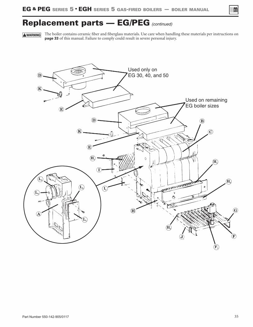
Part Number 550-142-905/0117 35
Replacement parts — EG/PEG (continued)
The boiler contains ceramic fiber and fiberglass materials. Use care when handling these materials per instructions on page 33 of this manual. Failure to comply could result in severe personal injury.
EG & PEG sEriEs 5 • EGH sEriEs 5 Gas-firEd boilErs — boilEr manual
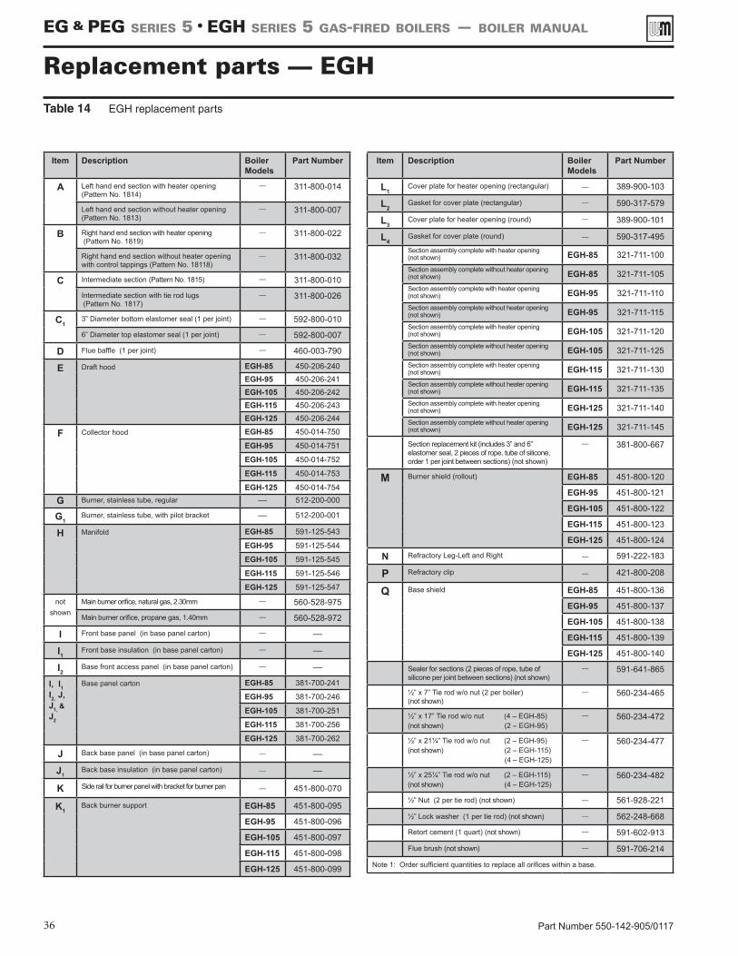
Part Number 550-142-905/011736
Replacement parts — EGHTable 14 EGH replacement parts
Item Description Boiler Models
Part Number
A Left hand end section with heater opening(Pattern No. 1814)
–– 311-800-014
Left hand end section without heater opening (Pattern No. 1813)
–– 311-800-007
B Right hand end section with heater opening (Pattern No. 1819)
–– 311-800-022
Right hand end section without heater opening with control tappings (Pattern No. 18118)
–– 311-800-032
C Intermediate section (Pattern No. 1815) –– 311-800-010
Intermediate section with tie rod lugs (Pattern No. 1817)
–– 311-800-026
C13” Diameter bottom elastomer seal (1 per joint) –– 592-800-010
6” Diameter top elastomer seal (1 per joint) –– 592-800-007
D Flue baffle (1 per joint) –– 460-003-790
E Draft hood EGH-85 450-206-240EGH-95 450-206-241EGH-105 450-206-242EGH-115 450-206-243EGH-125 450-206-244
F Collector hood EGH-85 450-014-750
EGH-95 450-014-751
EGH-105 450-014-752
EGH-115 450-014-753
EGH-125 450-014-754
G Burner, stainless tube, regular –– 512-200-000
G1Burner, stainless tube, with pilot bracket –– 512-200-001
H Manifold EGH-85 591-125-543
EGH-95 591-125-544
EGH-105 591-125-545
EGH-115 591-125-546
EGH-125 591-125-547
notshown
Main burner orifice, natural gas, 2.30mm –– 560-528-975
Main burner orifice, propane gas, 1.40mm –– 560-528-972
I Front base panel (in base panel carton) –– ––
I1Front base insulation (in base panel carton) –– ––
I2Base front access panel (in base panel carton) –– ––
I, I1 I2, J, J1, & J2
Base panel carton EGH-85 381-700-241
EGH-95 381-700-246
EGH-105 381-700-251
EGH-115 381-700-256
EGH-125 381-700-262
J Back base panel (in base panel carton) –– ––
J1Back base insulation (in base panel carton) –– ––
K Side rail for burner panel with bracket for burner pan –– 451-800-070
K1Back burner support EGH-85 451-800-095
EGH-95 451-800-096
EGH-105 451-800-097
EGH-115 451-800-098
EGH-125 451-800-099
Item Description Boiler Models
Part Number
L1Cover plate for heater opening (rectangular) –– 389-900-103
L2Gasket for cover plate (rectangular) –– 590-317-579
L3Cover plate for heater opening (round) –– 389-900-101
L4Gasket for cover plate (round) –– 590-317-495Section assembly complete with heater opening (not shown) EGH-85 321-711-100Section assembly complete without heater opening (not shown) EGH-85 321-711-105Section assembly complete with heater opening (not shown) EGH-95 321-711-110Section assembly complete without heater opening (not shown) EGH-95 321-711-115Section assembly complete with heater opening (not shown) EGH-105 321-711-120Section assembly complete without heater opening(not shown) EGH-105 321-711-125Section assembly complete with heater opening(not shown) EGH-115 321-711-130Section assembly complete without heater opening(not shown) EGH-115 321-711-135Section assembly complete with heater opening (not shown) EGH-125 321-711-140Section assembly complete without heater opening (not shown) EGH-125 321-711-145
Section replacement kit (includes 3” and 6” elastomer seal, 2 pieces of rope, tube of silicone, order 1 per joint between sections) (not shown)
–– 381-800-667
M Burner shield (rollout) EGH-85 451-800-120
EGH-95 451-800-121
EGH-105 451-800-122
EGH-115 451-800-123
EGH-125 451-800-124
N Refractory Leg-Left and Right –– 591-222-183
P Refractory clip –– 421-800-208
Q Base shield EGH-85 451-800-136
EGH-95 451-800-137
EGH-105 451-800-138
EGH-115 451-800-139
EGH-125 451-800-140
Sealer for sections (2 pieces of rope, tube of silicone per joint between sections) (not shown)
–– 591-641-865
½” x 7” Tie rod w/o nut (2 per boiler) (not shown)
–– 560-234-465
½” x 17” Tie rod w/o nut (4 – EGH-85) (not shown) (2 – EGH-95)
–– 560-234-472
½” x 21¼” Tie rod w/o nut (2 – EGH-95) (not shown) (2 – EGH-115) (4 – EGH-125)
–– 560-234-477
½” x 25¼” Tie rod w/o nut (2 – EGH-115) (not shown) (4 – EGH-125)
–– 560-234-482
½” Nut (2 per tie rod) (not shown) –– 561-928-221
½” Lock washer (1 per tie rod) (not shown) –– 562-248-668
Retort cement (1 quart) (not shown) –– 591-602-913
Flue brush (not shown) –– 591-706-214
Note 1: Order sufficient quantities to replace all orifices within a base.
EG & PEG sEriEs 5 • EGH sEriEs 5 Gas-firEd boilErs — boilEr manual
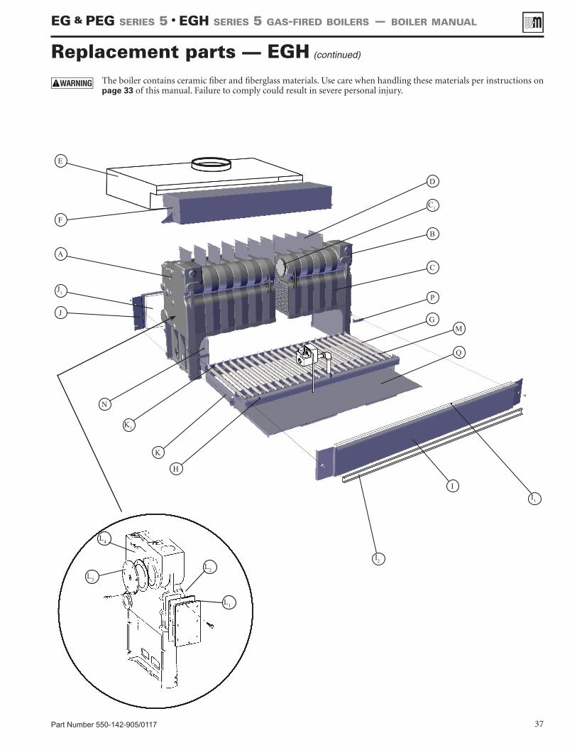
Part Number 550-142-905/0117 37
Replacement parts — EGH (continued)
EG & PEG sEriEs 5 • EGH sEriEs 5 Gas-firEd boilErs — boilEr manual
L4
L3
L2
L1
The boiler contains ceramic fiber and fiberglass materials. Use care when handling these materials per instructions on page 33 of this manual. Failure to comply could result in severe personal injury.
C1
F
E
A
J
N
B
C
P
Q
K
K1
H
D
I1
I2
M
J1
I
G
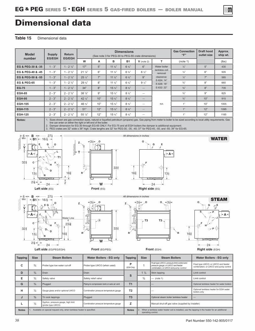
Part Number 550-142-905/011738
Dimensional dataTable 15 Dimensional data
Tapping Size Steam Boilers Water Boilers - EG only Tapping Size Steam Boilers Water Boilers - EG only
C ¾ Probe type low water cut-off Probe type LWCO (when used) P (EGH Only)
1Float type LWCO, pressure limit control and pressure gauge; or LWCO and feeder combination; or LWCO and pump control
Float type LWCO; or LWCO and feeder combination; or LWCO and pump control
D ¾ Drain DrainS
1 ½ Skim tapping Limit control
E ¾ Safety valve Safety relief valve ¾ –– (note 1) Limit control
G ¾ Plugged Piping to compression tank or auto air vent T1 –– Optional tankless heater for water boilers
H ½ Gauge glass and/or optional LWCO Combination pressure temperature gauge T2 –– Optional tankless heater for EGH water boilers only
J ⅜ Tri cock tappings Plugged T3 Optional steam boiler tankless heater ––
L ½ Syphon, pressure gauge, high limit (probe type LWCO)
Combination pressure temperature gauge Z Manual shut-off gas valve (supplied by installer)
Notes 1. Available on special request only, when tankless heater is specified. Notes 2. When a tankless water heater coil is installed, use the tapping in the heater for an additional operating control.
Model number
Supply EG/EGH
Return EG/EGH
Dimensions (See note 3 for PEG-30 to PEG-55 crate dimensions)
Gas Connection “F”
Draft hood outlet size
Approx. ship wt.
W A B B1 V (note 2) T (note 1) (lbs)
EG & PEG-30 & -35 1 - 3” 1 - 2 ½” 17” 5” 11 ¾” 6 ¾” 6” Water boiler tankless coil
removal clearance: E-624: 14” E-626: 18”E-632: 22”
½” 5” 430
EG & PEG-40 & -45 1 - 3” 1 - 2 ½” 21 ¼” 6” 11 ¾” 6 ¾” 6 ½” ½” 6” 505
EG & PEG-50 & -55 1 - 3” 1 - 2 ½” 25 ½” 7” 11 ¾” 6 ¾” 9” ½” 7” 585
EG & PEG-65 1 - 3” 1 - 2 ½” 29 ¾” 8” 11 ¾” 6 ¾” 9 ½” ¾” 8” 660
EG-75 1 - 3” 1 - 2 ½” 34” 8” 15 ¾” 8 ¾” –– ¾” 8” 735
EGH-85 2 - 3” 2 - 2 ½” 38 ¼” 9” 15 ¾” 8 ¾” ––
N/A
¾” 9” 825
EGH-95 2 - 3” 2 - 2 ½” 42 ½” 10” 15 ¾” 8 ¾” –– ¾” 10” 915
EGH-105 2 - 3” 2 - 2 ½” 46 ¾” 10” 15 ¾” 8 ¾” –– 1” 10” 1005
EGH-115 2 - 3” 2 - 2 ½” 51” 12” 15 ¾” 8 ¾” –– 1” 12” 1095
EGH-125 2 - 3” 2 - 2 ½” 55 ¼” 12” 15 ¾” 8 ¾” –– 1” 12” 1185
Notes: 1. Sizes shown are gas connection sizes, natural or liquefied petroleum (propane) gas. Gas piping from meter to boiler to be sized according to local utility requirements. Gas line can enter on either the right or left end of the boiler.
2. Damper dimension for EG-30 through EG-65 ONLY. For EG-75 and all EGH boilers the damper is additional equipment.3. PEG crates are 32” wide x 39” high. Crate lengths are 32” for PEG-30, -35, -40; 37” for PEG-45, -50, and -55; 39” for EG-65.
EG & PEG sEriEs 5 • EGH sEriEs 5 Gas-firEd boilErs — boilEr manual
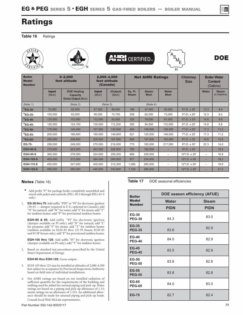
Boiler ModelNumber
DOE season efficiency (AFUE)
Water SteamPIDN PIDN
EG-30PEG-30
84.3 83.0
EG-35PEG-35
83.6 82.9
EG-40PEG-40 84.0 82.9
EG-45PEG-45 83.5 82.9
EG-50PEG-50 83.8 82.8
EG-55PEG-55 83.8 82.8
EG-65PEG-65 84.0 83.0
EG-75 82.7 82.4
Part Number 550-142-905/0117 39
Notes (Table 16)
* Add prefix “P” for package boiler completely assembled and wired with jacket and controls (PEG-30-S through PEG-65-S only).
1. EG-30 thru 75: Add suffix “PID” or “PI” for electronic ignition (30-65 — damper required in U.S.; optional in Canada); add “N” for natural; add “W” for water; add “S” for steam; add “T” for tankless heater; add “P” for provisional tankless heater.
EGH-85 & 95: Add suffix “PI” for electronic ignition (damper available on PI only); add “N” for natural; add “L” for propane; add “S” for steam; add “T” for tankless heater (tankless available on EGH-85 thru 125 PI Steam; EGH-85 and 95 SP Steam only); add “P” for provisional tankless heater.
EGH-105 thru 125: Add suffix “PI” for electronic ignition (damper available on PI only); add “T” for tankless heater.
2. Based on standard test procedures prescribed by the United States Department of Energy.
EGH-85 thru EGH-125: Gross output.
3. EGH-105 thru 125 may be installed at altitudes of 2,000-4,500 feet subject to acceptance by Provincial Inspections Authority based on field tests of individual installations.
4. Net AHRI ratings are based on net installed radiation of sufficient quantity for the requirements of the building and nothing need be added for normal piping and pick-up. Water ratings are based on a piping and pick-up allowance of 1.15; steam ratings on an allowance of 1.333. An additional allow-ance should be made for unusual piping and pick-up loads. Consult local Weil-McLain representative.
Table 17 DOE seasonal efficiencies
Ratings
Boiler ModelNumber
0–2,000 feet altitude
2,000–4,500feet altitude
(Canada)
Net AHRI Ratings ChimneySize
Boiler Water Content(Gallons)
Input(Btuh)
DOE HeatingCapacity
Gross Output (Btuh)
Input(Btuh)
(Output) (Btuh)
Sq. Ft.Steam
Steam Btuh
Water Btuh
Water Steam(to Waterline)
(Note 1) (Note 2) (Note 3) (Note 4)
*EG-30- 75,000 62,000 67,500 56,000 196 47,000 55,000 5"I.D. x 20' 12.3 8.4
*EG-35- 100,000 83,000 90,000 74,700 258 62,000 73,000 5"I.D. x 20' 12.3 8.4
*EG-40- 125,000 103,900 112,000 93,000 325 78,000 91,000 6"I.D. x 20' 14.8 9.8
*EG-45- 150,000 124,700 135,000 112,200 392 94,000 110,000 6"I.D. x 20' 14.8 9.8
*EG-50- 175,000 145,400 157,500 130,900 454 109,000 128,000 7"I.D. x 20' 17.3 11.2
*EG-55- 200,000 166,600 180,000 149,900 521 125,000 146,000 7"I.D. x 20' 17.3 11.2
*EG-65- 250,000 208,800 225,000 187,900 654 157,000 183,000 8"I.D. x 20' 19.8 12.6
EG-75- 299,000 249,000 270,000 216,000 770 185,000 217,000 8"I.D. x 20' 22.3 14.0
EGH-85-S 315,000 243,000 283,500 226,800 760 182,000 – 9"I.D. x 20' – 15.4
EGH-95-S 360,000 278,000 324,000 259,200 868 208,000 – 10"I.D. x 20' – 16.8
EGH-105-S 405,000 312,000 364,500 280,800 977 234,000 – 10"I.D. x 20' – 18.2
EGH-115-S 450,000 347,000 405,000 312,300 1,085 260,000 – 12"I.D. x 20' – 19.6
EGH-125-S 495,000 382,000 445,500 343,800 1,193 286,000 – 12"I.D. x 20' – 21.0
Table 16 Ratings
EG & PEG sEriEs 5 • EGH sEriEs 5 Gas-firEd boilErs — boilEr manual
DOE
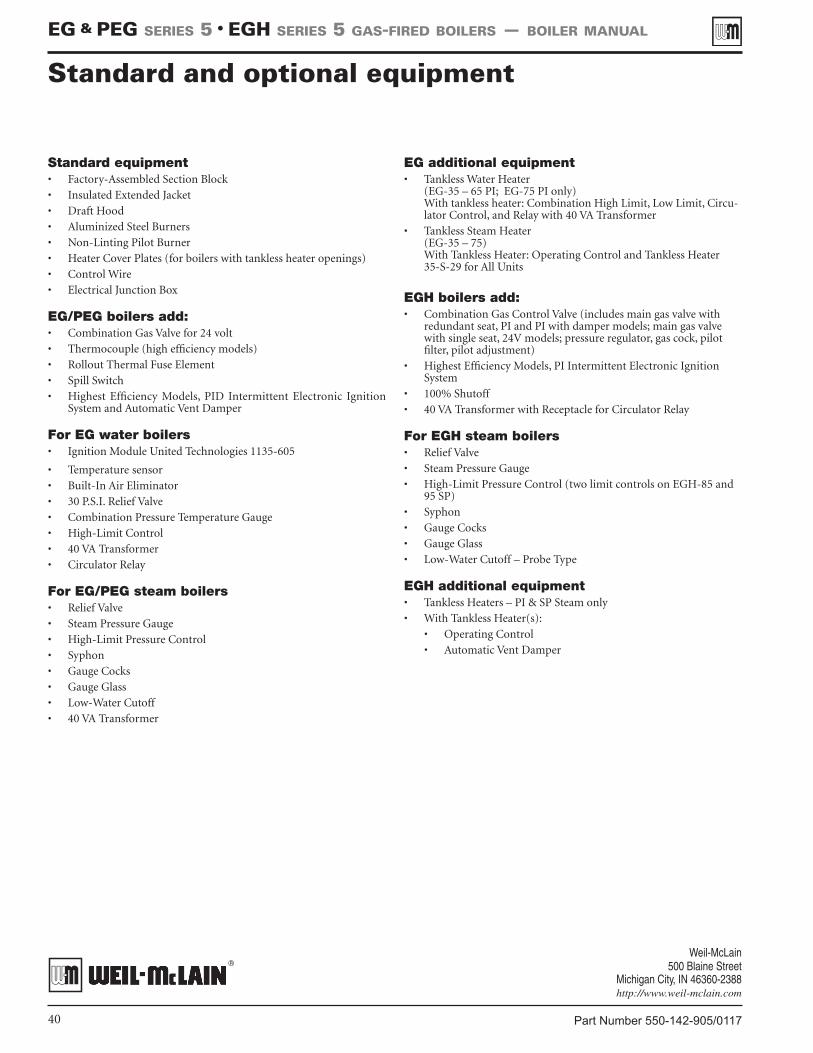
Part Number 550-142-905/011740
EG & PEG sEriEs 5 • EGH sEriEs 5 Gas-firEd boilErs — boilEr manual
Standard equipment• Factory-Assembled Section Block
• Insulated Extended Jacket
• Draft Hood
• Aluminized Steel Burners
• Non-Linting Pilot Burner
• Heater Cover Plates (for boilers with tankless heater openings)
• Control Wire
• Electrical Junction Box
EG/PEG boilers add: • Combination Gas Valve for 24 volt
• Thermocouple (high efficiency models)
• Rollout Thermal Fuse Element
• Spill Switch
• Highest Efficiency Models, PID Intermittent Electronic Ignition System and Automatic Vent Damper
For EG water boilers• Ignition Module United Technologies 1135-605
• Temperature sensor
• Built-In Air Eliminator
• 30 P.S.I. Relief Valve
• Combination Pressure Temperature Gauge
• High-Limit Control
• 40 VA Transformer
• Circulator Relay
For EG/PEG steam boilers• Relief Valve
• Steam Pressure Gauge
• High-Limit Pressure Control
• Syphon
• Gauge Cocks
• Gauge Glass
• Low-Water Cutoff
• 40 VA Transformer
EG additional equipment • Tankless Water Heater
(EG-35 – 65 PI; EG-75 PI only) With tankless heater: Combination High Limit, Low Limit, Circu-lator Control, and Relay with 40 VA Transformer
• Tankless Steam Heater (EG-35 – 75) With Tankless Heater: Operating Control and Tankless Heater 35-S-29 for All Units
EGH boilers add: • Combination Gas Control Valve (includes main gas valve with
redundant seat, PI and PI with damper models; main gas valve with single seat, 24V models; pressure regulator, gas cock, pilot filter, pilot adjustment)
• Highest Efficiency Models, PI Intermittent Electronic Ignition System
• 100% Shutoff
• 40 VA Transformer with Receptacle for Circulator Relay
For EGH steam boilers• Relief Valve
• Steam Pressure Gauge
• High-Limit Pressure Control (two limit controls on EGH-85 and 95 SP)
• Syphon
• Gauge Cocks
• Gauge Glass
• Low-Water Cutoff – Probe Type
EGH additional equipment• Tankless Heaters – PI & SP Steam only
• With Tankless Heater(s):
• Operating Control
• Automatic Vent Damper
Standard and optional equipment