Embed Size (px)
Citation preview

BRGM GFZ
EGS Technology: hydraulic fraccing: oil and gas and shale gas best practive
BRGM GFZ
Content
rationale
Borehole Stress and failure
What applications for hydraulic fracturing (general)
How does it work (theory and operational)
Models vs reality
Fracture aperture and permeability
What did we learn from gas shales
BRGM GFZ
Useful books
E. Fjaer et al
Petroleum Related Rock Mechanics
2nd edition
J. Jaeger, N.G. Cook & R. Zimmermann
Fundamentals of Rock Mechanics
George E. King
Thirty Years of Gas Shale Fracturing: What Have We Learned?
SPE 133456
Kevin Fisher
SPE YP presentation : Hydraulic Fracturing: Modeling vs. Reality

BRGM GFZ
(www.soultz.net)
•EU research project > 20 years
•3 wells > 5 Km deep
•Comprehensive Fracturing programe
•3MWel Power via ORC plant
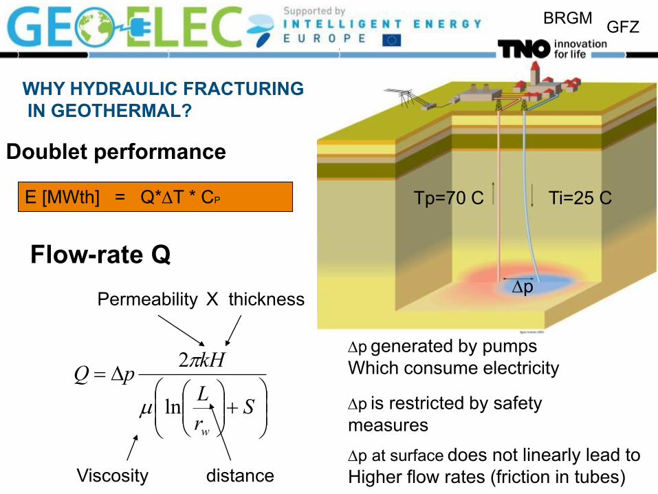
Enhanced Geothermal Systems WHY HYDRAULIC FRACTURING IN GEOTHERMAL?
BRGM GFZ
Doublet performance
Flow-rate Q Dp
Dp generated by pumps
Which consume electricity
Dp is restricted by safety
measures
Dp at surface does not linearly lead to
Higher flow rates (friction in tubes)
Permeability X thickness
Viscosity distance
D
Sr
L
kHpQ
w
ln
2
E [MWth] = Q*DT * CP Tp=70 C Ti=25 C
WHY HYDRAULIC FRACTURING
IN GEOTHERMAL?
BRGM GFZ
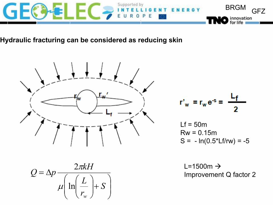
Hydraulic fracturing can be considered as reducing skin
D
Sr
L
kHpQ
w
ln
2
Lf = 50m
Rw = 0.15m
S = - ln(0.5*Lf/rw) = -5
L=1500m
Improvement Q factor 2

BRGM GFZ
Effect of hydraulic fraccing
0
0,5
1
1,5
2
2,5
3
3,5
4
4,5
0 5 10 15 20
Doublet Power (MWth) / Costs of Energy (EUR/GJ)
De
pth
(km
)
0 20 40 60 80 100
Tranmissivity (Dm)
DoubletPower orig.
Costs ofEnergy orig.
DoubletPower
Costs ofEnergy
Transmissivity
Transmissivity
BRGM GFZ
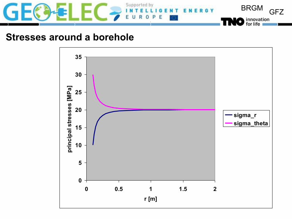
Stresses around a borehole
0
5
10
15
20
25
30
35
0 0.5 1 1.5 2
r [m]
pri
nc
ipa
l s
tre
ss
es
[M
Pa
]
sigma_r
sigma_theta

BRGM GFZ
Effect of Fluid Pressure – Net Stress
The sand grains in the
rock “feel” the net stress:
Question: What happens to the Mohr circle and the failure criterion?
Effects the horizontal position
Iσσ p'
sh’ 0.5(sh’+sH’) sH’
t
2q
(s,t)
2q
(s’,t)
αp
sh 0.5(sh+sH) sH s,s’

BRGM GFZ
Hydraulic fracturing – Applications
Frac & Pack
Weak, permeable formations
Bypass skin
Sand control
Massive Hydraulic Fracturing
(EGS, aquifers)
Low-permeability reservoir
Usually first minifrac test
Fracture pressure
Containment
Leakoff behavior
Stimulating naturally fractured
reservoir
Activate fracture network
E.g. unconventional shale gas
Water injection
Maintain injectivity
Thermal fracturing
Leakoff tests, Extended leakoff
tests
Fracture gradient
Mininum in-situ stress
Waste disposal
Drill cuttings
Produced water
BRGM GFZ
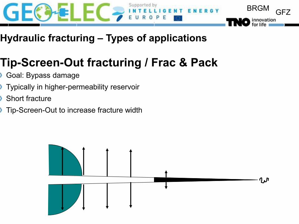
Hydraulic fracturing – Types of applications
Tip-Screen-Out fracturing / Frac & Pack Goal: Bypass damage
Typically in higher-permeability reservoir
Short fracture
Tip-Screen-Out to increase fracture width
BRGM GFZ
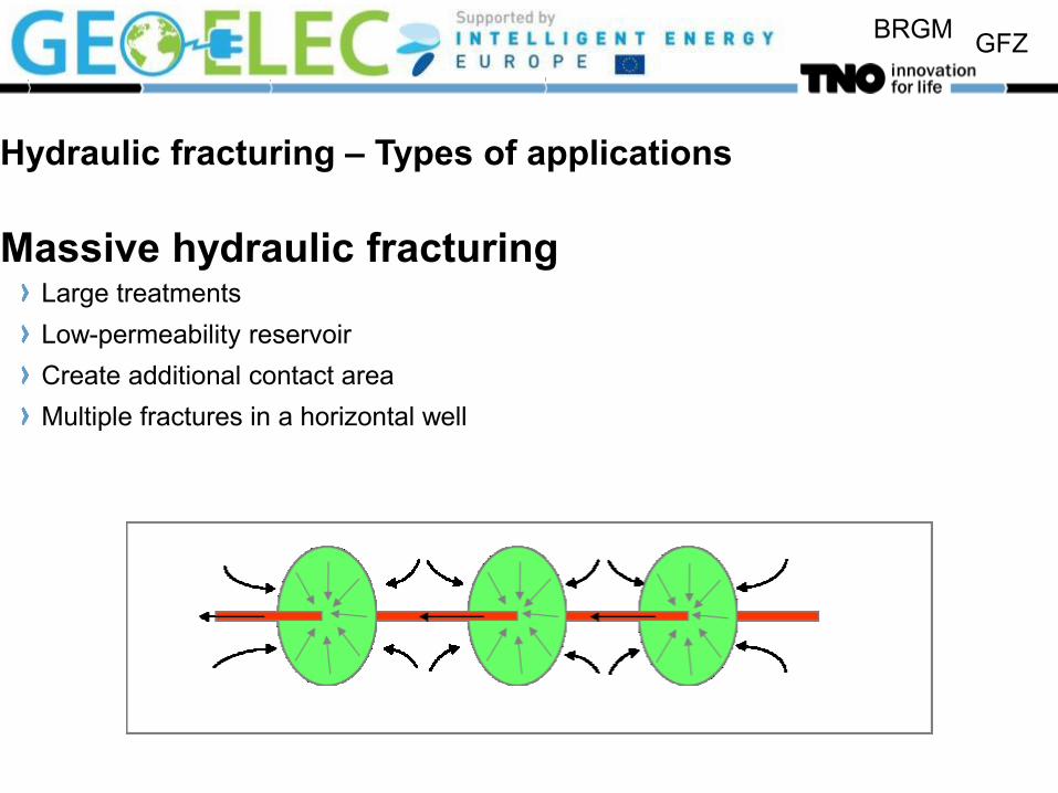
Hydraulic fracturing – Types of applications
Massive hydraulic fracturing Large treatments
Low-permeability reservoir
Create additional contact area
Multiple fractures in a horizontal well
BRGM GFZ
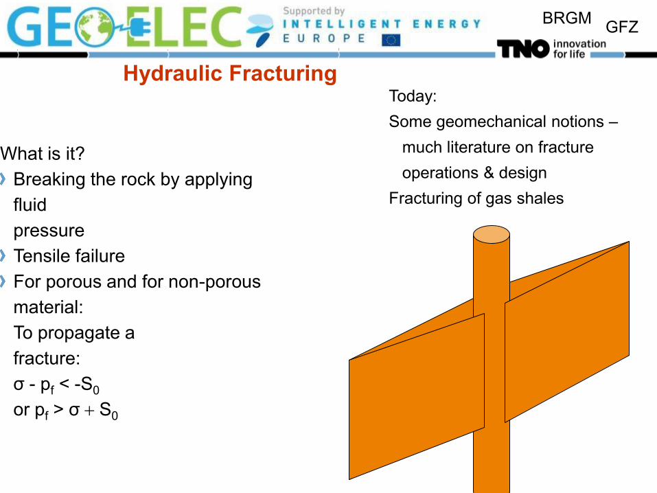
Hydraulic Fracturing
What is it?
Breaking the rock by applying
fluid
pressure
Tensile failure
For porous and for non-porous
material:
To propagate a
fracture:
σ - pf < -S0
or pf > σ S0
Today:
Some geomechanical notions –
much literature on fracture
operations & design
Fracturing of gas shales

BRGM GFZ
Physical process
pf>closure stress(sc ==sh)
Hydra
ulic
fraccin
g
Shut-in
Elastic closure
Leakoff
Pf==sc

BRGM GFZ
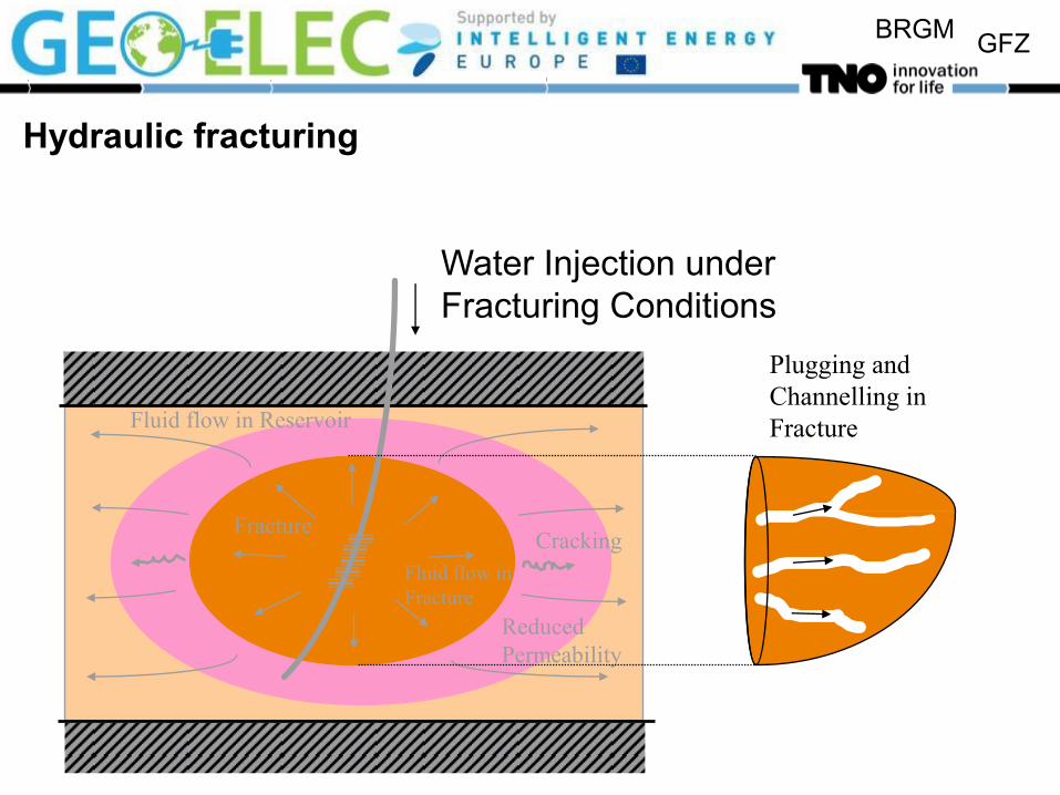
Hydraulic fracturing
Cracking
Fluid flow in Reservoir
Fluid flow in
Fracture
Plugging and
Channelling in
Fracture
Reduced
Permeability
Fracture
Water Injection under
Fracturing Conditions
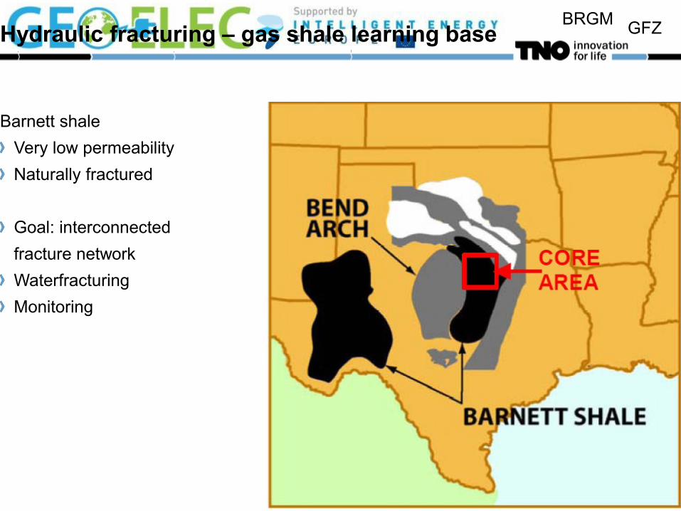
BRGM GFZ Hydraulic fracturing – gas shale learning base
Barnett shale
Very low permeability
Naturally fractured
Goal: interconnected
fracture network
Waterfracturing
Monitoring

BRGM GFZ
Hydraulic fracturing – Basic concepts
Stress: maximum stress vertical;
minimum and medium stresses
horizontal
Modes of fracturing
Hydraulic fracturing: Tensile (mode I) – Vertical fracture has least resistance
s1
s3
s2
Mode I: Opening Mode III: TearingMode II: Sliding

BRGM GFZ
Hydraulic Fracturing
• Tensile failure, NOT shear failure • Orientation of the fracture: that direction
where pf > σ T0 first, i.e. σ is minimal (T0: tensile strength)
• The normal stress on the fracture wall “tries” to close the fracture
• Therefore the orientation is • Perpendicular to the minimum in-
situ stress direction • Parallel to the medium and the
maximum in-situ stress direction • Vertical • Sometimes horizontal for very
shallow fractures

BRGM GFZ
Hydraulic Fracturing – Coupled Processes
BRGM GFZ
Hydraulic fracturing
Cracking
Fluid flow in Reservoir
Fluid flow in
Fracture
Plugging and
Channelling in
Fracture
Reduced
Permeability
Fracture
Water Injection under
Fracturing Conditions
BRGM GFZ
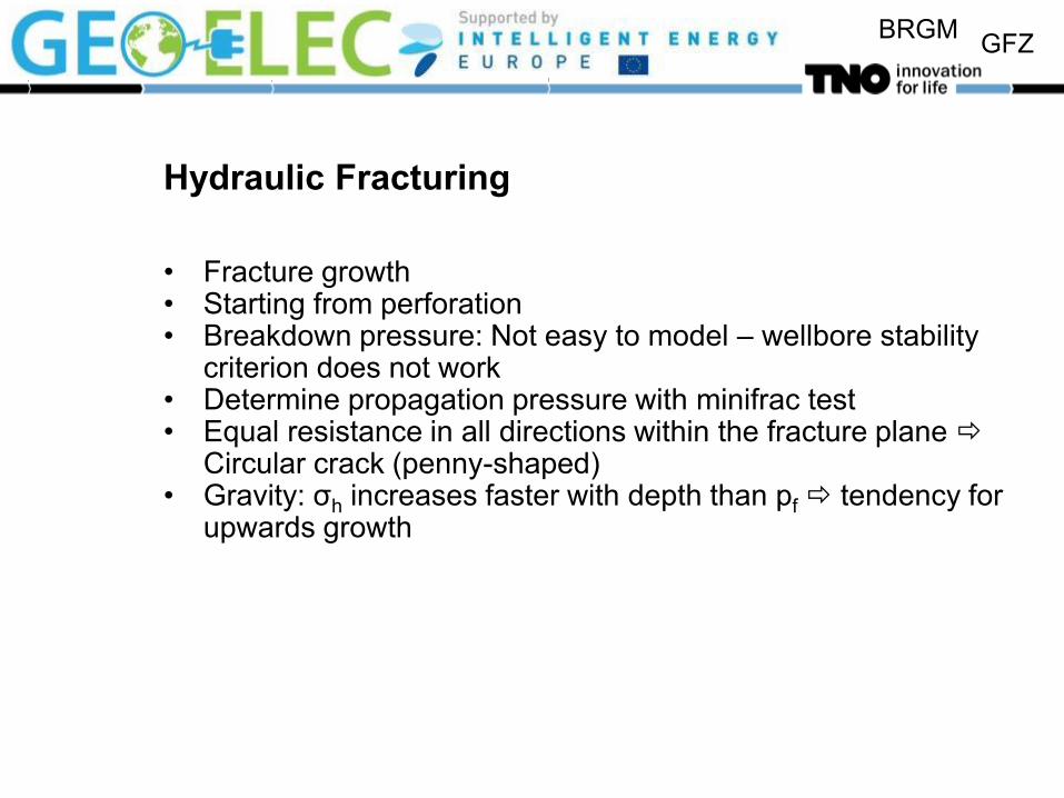
Hydraulic Fracturing
• Fracture growth • Starting from perforation • Breakdown pressure: Not easy to model – wellbore stability
criterion does not work • Determine propagation pressure with minifrac test • Equal resistance in all directions within the fracture plane
Circular crack (penny-shaped) • Gravity: σh increases faster with depth than pf tendency for
upwards growth
BRGM GFZ
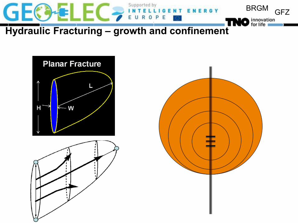
Hydraulic Fracturing – growth and confinement

BRGM GFZ
1800
2000
2200
2400
2600
2800
3000
3200
3400
0 20 40 60 80
Stress [MPa]
De
pth
[m
]
Hydraulic Fracturing
Lithography induces contrasts
in minimum in-situ stress
Lithgraphic density: 2200 kg /
m3
Fluid density:
1000 kg / m3
gzf
zh
s
s
1
21
1
gzz s
=
0.4
=
0.3
=
0.4
Poisson’s ratio [-]
0 1

BRGM GFZ
Hydraulic fracturing – Concept
KI: Stress intensity – measure of singular stress behaviour beyond the tip Length increases when KI > KIc Volume balance Elastic opening Leakoff correlation
s
t
leakoffpenetrated
frac
penetratedresfracleakoff
fracture
leakoffleakoff
leakoffinj
fracture
fracture
IcI
I
dtvd
EL
wp
dppv
dAvQ
QQdt
dV
A
Vw
KK
AwfK
0
3
'
,

BRGM GFZ
dep
th
injection
σh
Fracture vs time
Hydraulic Fracturing – Effect of layering, confinement
Layering
Elasticity
Stress
Permeability
Porosity
BRGM GFZ
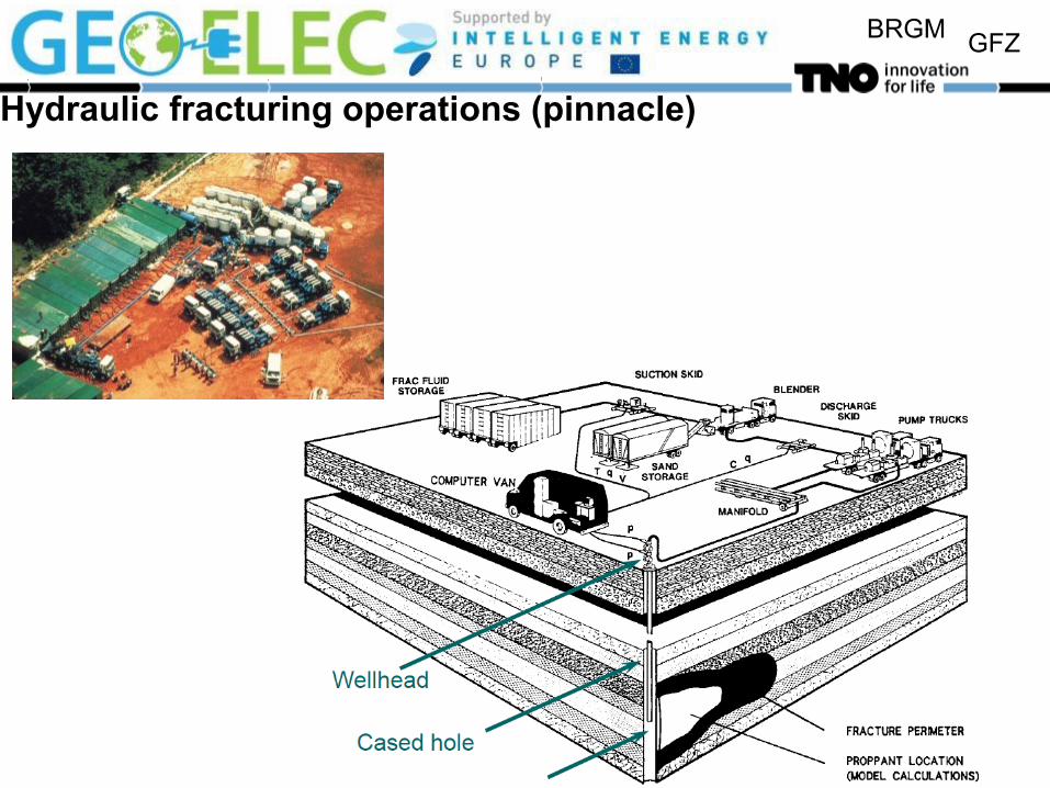
Hydraulic fracturing operations (pinnacle)
BRGM GFZ
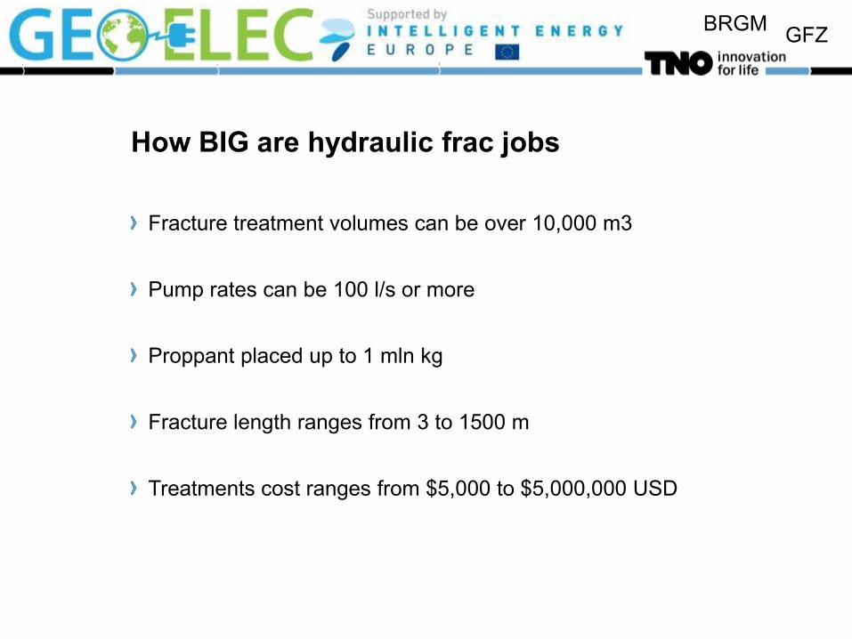
How BIG are hydraulic frac jobs
Fracture treatment volumes can be over 10,000 m3
Pump rates can be 100 l/s or more
Proppant placed up to 1 mln kg
Fracture length ranges from 3 to 1500 m
Treatments cost ranges from $5,000 to $5,000,000 USD

BRGM GFZ
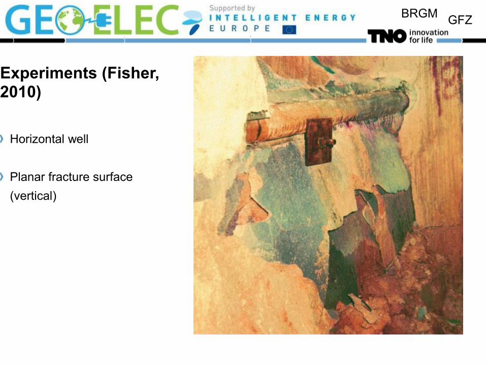
Experiments (Fisher, 2010)
BRGM GFZ
Experiments (Fisher, 2010)
Horizontal well
Planar fracture surface
(vertical)
BRGM GFZ
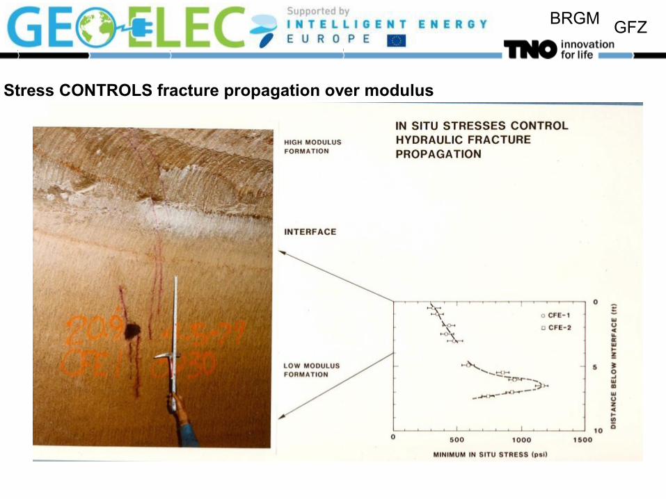
Stress CONTROLS fracture propagation over modulus
BRGM GFZ
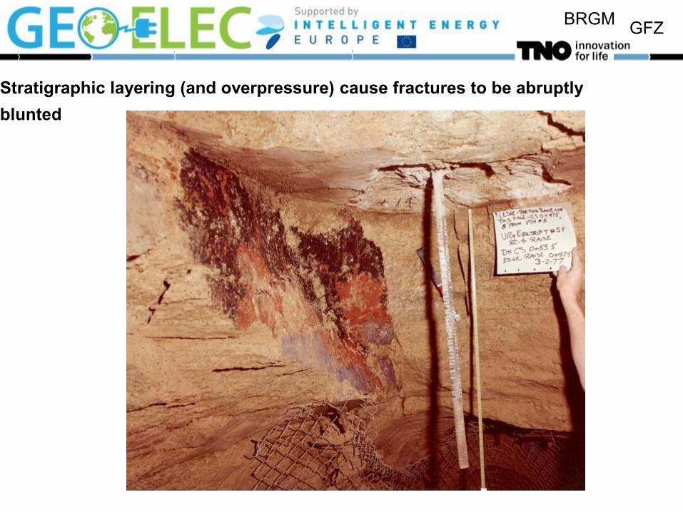
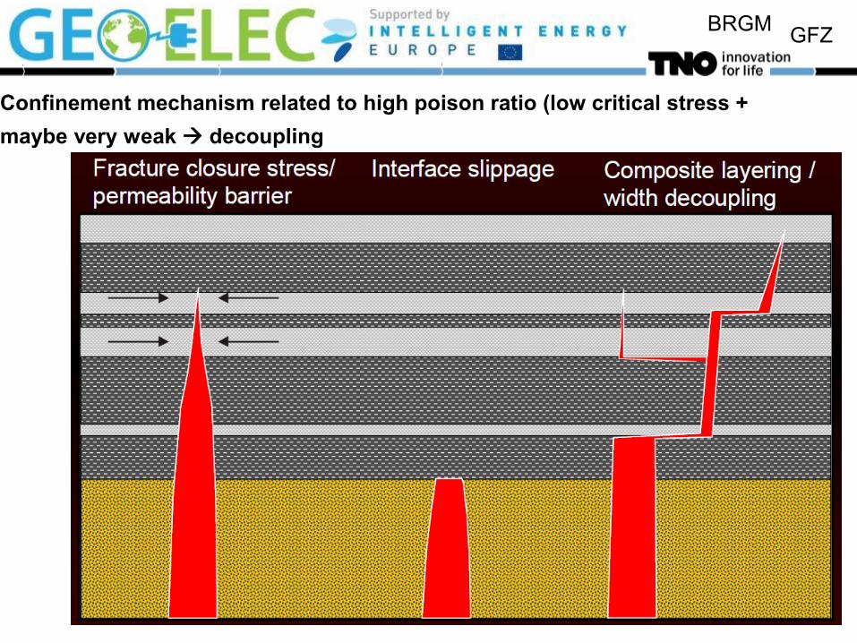
Stratigraphic layering (and overpressure) cause fractures to be abruptly
blunted
BRGM GFZ
Confinement mechanism related to high poison ratio (low critical stress +
maybe very weak decoupling
BRGM GFZ
BRGM GFZ
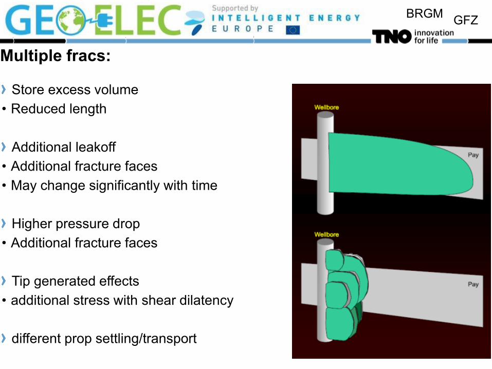
Multiple fracs:
Store excess volume
• Reduced length
Additional leakoff
• Additional fracture faces
• May change significantly with time
Higher pressure drop
• Additional fracture faces
Tip generated effects
• additional stress with shear dilatency
different prop settling/transport

BRGM GFZ
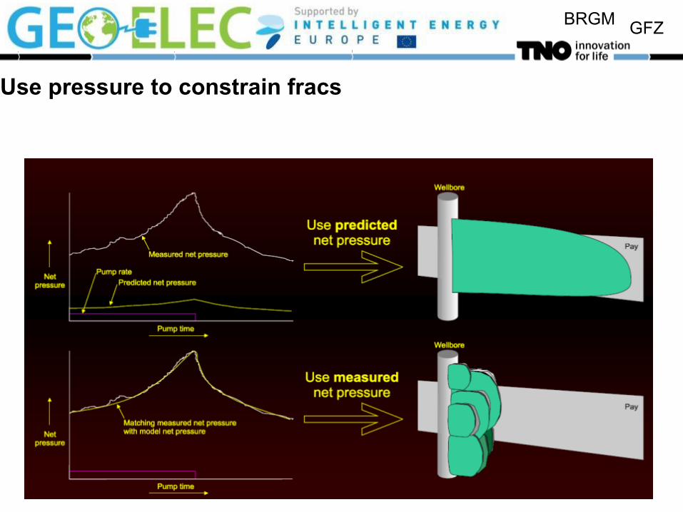
Modelling versus measuring
Fracture
growth models incomplete physical
understanding
Mapping
diagnostics not predictive
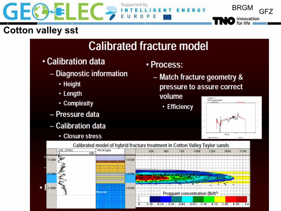
Calibrated models more
realistically predict how
fractures will grow for
alternative designs

BRGM GFZ
An example of a model:Effect of Stress Gradient and Stress Contrast
900
950
1000
1050
1100
1150
1200
1250
1300
0 2000 4000 6000 8000
Time (days)
De
pth
(m
)
0
50
100
150
200
250
300
350
400
Fra
ctu
re le
ng
th (
m)
Fracture
height
Fracture length
Shale layer
Ds = 0 MPa
Ds = 1 MPa
Ds = 2 MPa
Ds = 3 MPa
Increased stress
in shale layer

BRGM GFZ
Width and length contours (Ds = 2 MPa)

BRGM GFZ
What can we measure/ESTIMATE
• Lithology (logs) • Gamma Ray (GR)
• dynamic modulus (E) and • poision ratio (v)
• Micro-seismicity (shear failure only) • Stress (special measurements MRX) • Pressure • Tilt meters

BRGM GFZ
Preferably do a mini-frac test
More input for design:
In-situ stresses
Fracturing pressures Minifrac test
Leakoff behaviour
ISIP = initial shut –in
Pressure
Shut-in time
}
BRGM GFZ
Use pressure to constrain fracs

BRGM GFZ Stress changes during fracturing

BRGM GFZ
Sometimes model predictions and measurements agree well

BRGM GFZ
But in other cases not

BRGM GFZ
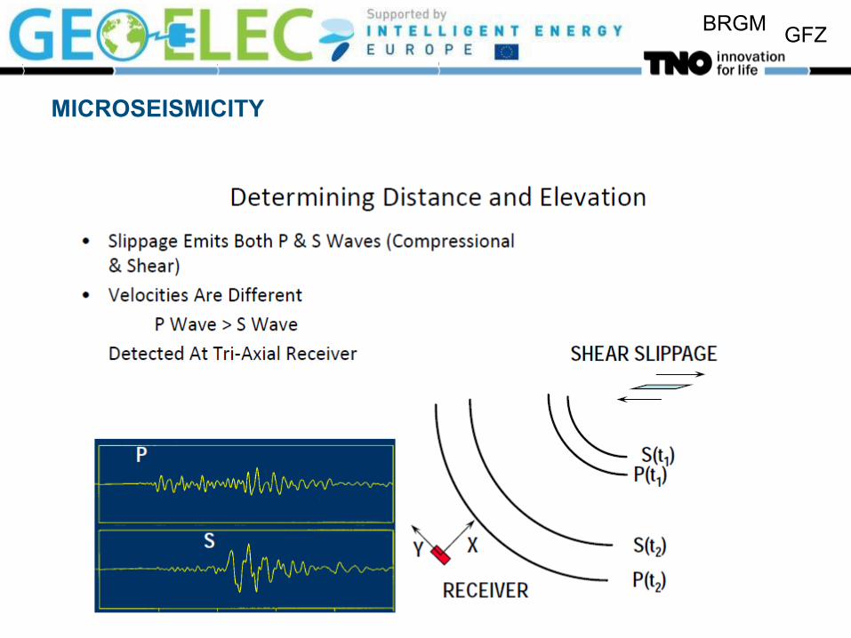
MICROSEISMICITY
BRGM GFZ
MICROSEISMICITY
BRGM GFZ
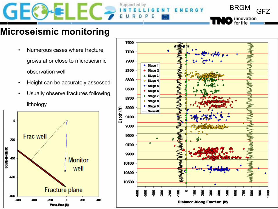
Microseismic monitoring
• Numerous cases where fracture
grows at or close to microseismic
observation well
• Height can be accurately assessed
• Usually observe fractures following
lithology

BRGM GFZ
Fracture containment AS a conseqence of strength of surrounding layers
Variable containment in shales
• Containment (e.g., Barnett)
• Bounded by carbonates
• Upward growth
• Continuous shale
Faulting effects

BRGM GFZ
Microseismic data and model calibration-cotton valley sst
BRGM GFZ
Cotton valley sst

BRGM GFZ
Offset due to natural fractures and faults

BRGM GFZ
microseismicity shows shear fractures
how about shear fracture mechanisms, aperture and permeability?
BRGM GFZ
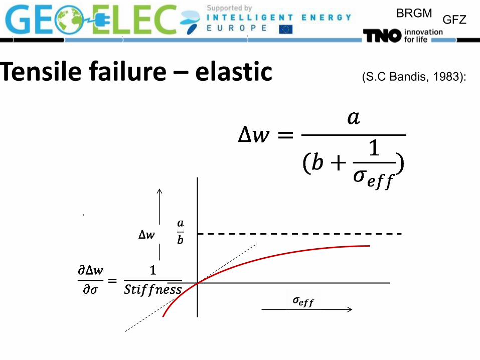
Tensile failure – elastic (S.C Bandis, 1983):

BRGM GFZ
Tensile failure - elastic
BRGM GFZ
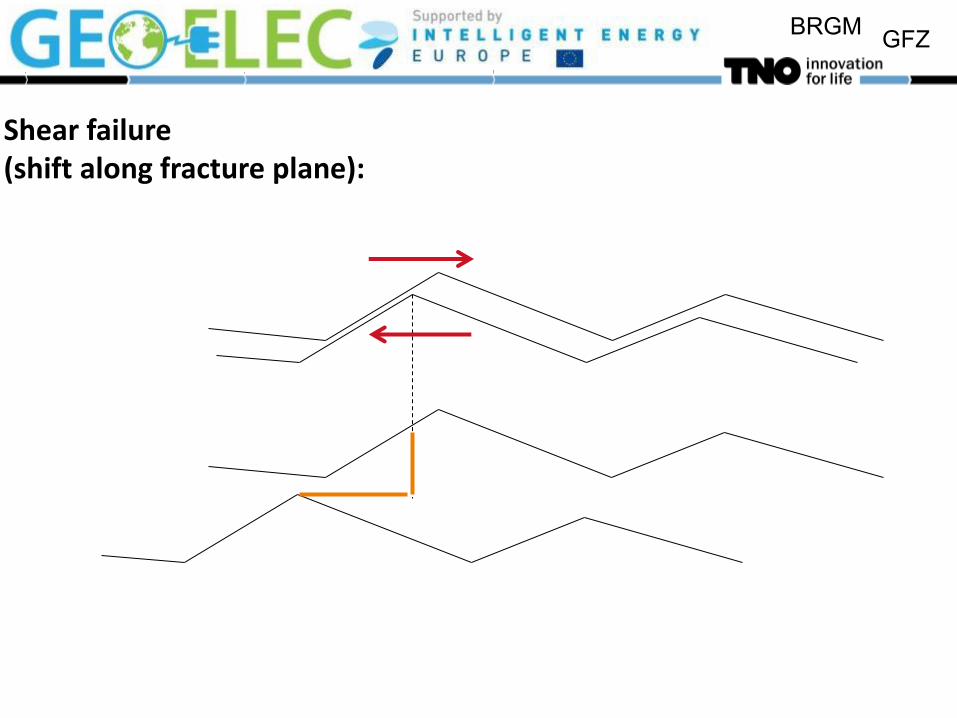
Shear failure (shift along fracture plane):

BRGM GFZ
Shear failure
(T. Kohl et al, 2007)
BRGM GFZ
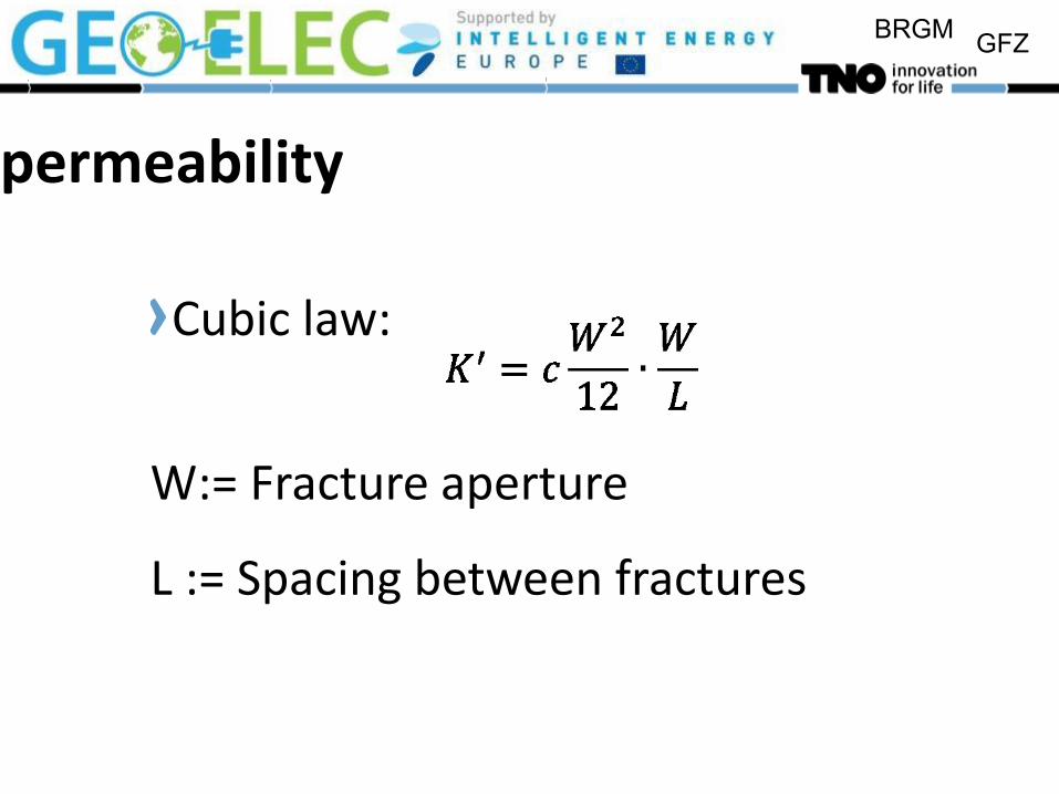
permeability Cubic law:
W:= Fracture aperture
L := Spacing between fractures
BRGM GFZ
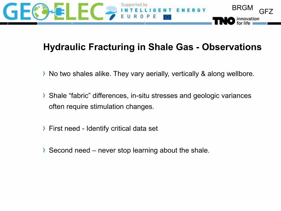
Hydraulic Fracturing in Shale Gas - Observations
No two shales alike. They vary aerially, vertically & along wellbore.
Shale “fabric” differences, in-situ stresses and geologic variances
often require stimulation changes.
First need - Identify critical data set
Second need – never stop learning about the shale.
BRGM GFZ
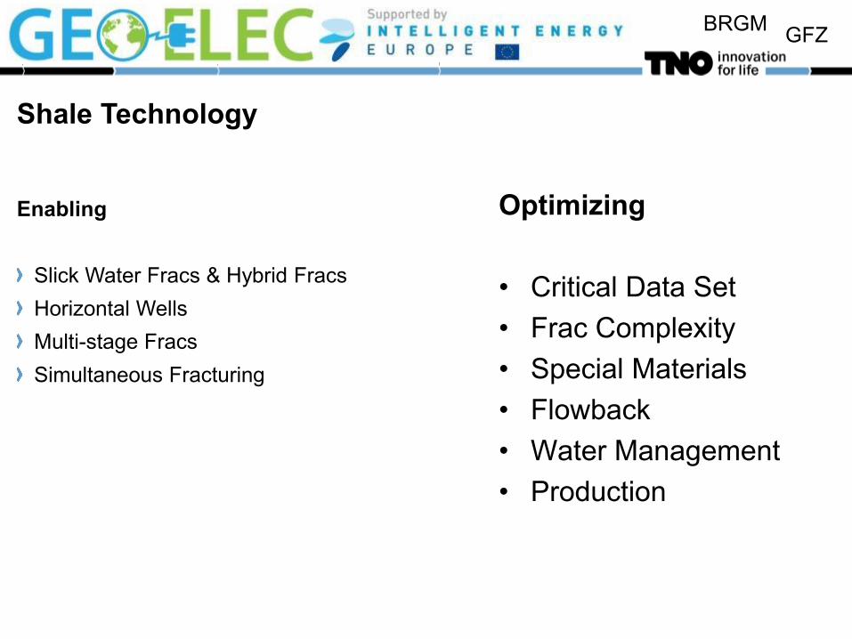
Shale Technology
Enabling
Slick Water Fracs & Hybrid Fracs
Horizontal Wells
Multi-stage Fracs
Simultaneous Fracturing
Optimizing
• Critical Data Set
• Frac Complexity
• Special Materials
• Flowback
• Water Management
• Production

BRGM GFZ
BRGM GFZ
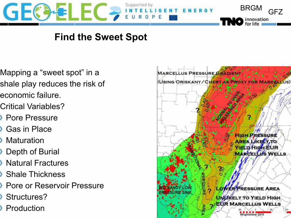
Find the Sweet Spot
Mapping a “sweet spot” in a
shale play reduces the risk of
economic failure.
Critical Variables?
Pore Pressure
Gas in Place
Maturation
Depth of Burial
Natural Fractures
Shale Thickness
Pore or Reservoir Pressure
Structures?
Production

BRGM GFZ
Critical Factors vs. Critical Data Set
Factors describe the shale to be evaluated – not the whole play.
Data sets include:
How to get the most accurate & representative data for the specific
shale.
Knowledge of what operations are needed to optimize production.
“Must have data” includes environmental concerns and resolutions

BRGM GFZ
Natural fracture systems
Natural pathways. Open at 50 to 60% of rock frac pressure. Open by low viscosity fluid invasion. Difficult to prop. Dominate Permeability
BRGM GFZ
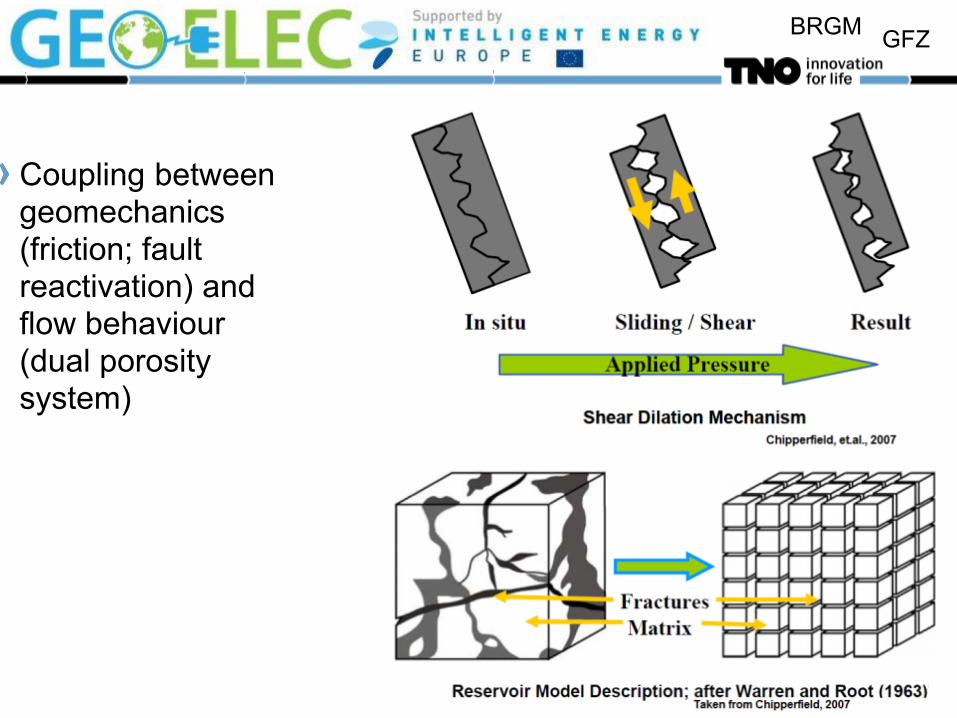
Coupling between geomechanics (friction; fault reactivation) and flow behaviour (dual porosity system)

BRGM GFZ
Effect of elastic / plastic behaviour
Brittle shales are more easily fractured
Soft material: Healing of fractures
Dynamic E=sonic
Static E=mechanical
experiment

BRGM GFZ
Design
The goal: Maximize frac contact with shale.
Wellbore orientation (for transverse induced fractures)
Wellbore length
Toe up or down?
Number of Frac Stages
How to place: by average distance or gas shows?
Spacing, number, holes? Interference?
Hydraulic diversion?

BRGM GFZ
Re-Fracturing
They Work – But Why? Old fractures with gel
Slick water fracturing
connects to larger part of
reservoir
Change of stress orientation

BRGM GFZ
Fracture Network Complexity
Complexity develops if natural fracture system is connected to induced fracture
and opened
Observed with microseismic monitoring

BRGM GFZ
Proppant placement
Proppant settles due to low water viscosity Unpropped fracture part still contributes to flow through propped part Distinction between brittle material (fractures stay) and ductile material (fractures heal)
BRGM GFZ
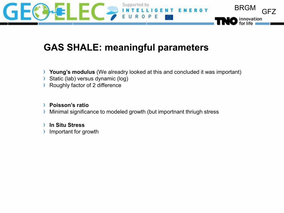
GAS SHALE: meaningful parameters
Young’s modulus (We alreadry looked at this and concluded it was important)
Static (lab) versus dynamic (log)
Roughly factor of 2 difference
Poisson’s ratio
Minimal significance to modeled growth (but importnant thriugh stress
In Situ Stress
Important for growth
BRGM GFZ
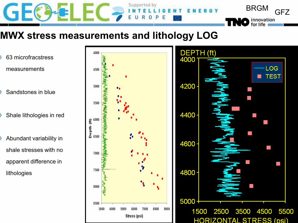
MWX stress measurements and lithology LOG
63 microfracstress
measurements
Sandstones in blue
Shale lithologies in red
Abundant variability in
shale stresses with no
apparent difference in
lithologies

BRGM GFZ
Water Management
Cleanup water produced back early
Use produced water for later fracture treatments
Economic and Ecologic advantages
BRGM GFZ
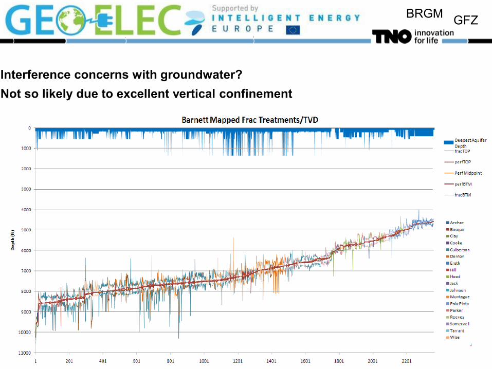
Interference concerns with groundwater?
Not so likely due to excellent vertical confinement

BRGM GFZ
Hydraulic Fracturing – Other Issues
Treatment Design
Required Productivity
“Tip Screen Out” design
Minifrac analysis
In-situ stress
Leakoff behaviour
Fracture containment
Fracture characterization
P & Q recording
Tiltmeters
Induced seismicity
Proppant properties
Productivity calculation
Sand control
Strength
Frac fluid properties
Leakoff control
Proppant placement
Cleanup
Unconventional fracturing
Naturally fractured low perm
(Barnett shales)