Embed Size (px)
Citation preview

BRGM GFZ
EGS Technology: hydraulic fraccing:il d d h l b t tioil and gas and shale gas best practice

BRGM GFZ
Content
rationale
Borehole Stress and failure
What applications for hydraulic fracturing (general)
How does it work (theory and operational)
Models vs reality
Fracture aperture and permeabilityFracture aperture and permeability
What did we learn from gas shales

BRGM GFZ
Useful books
E. Fjaer et alPetroleum Related Rock Mechanics2nd edition
J. Jaeger, N.G. Cook & R. ZimmermannFundamentals of Rock Mechanics
George E. King Thirty Years of Gas Shale Fracturing: What Have We Learned? SPE 133456
Kevin FisherSPE YP presentation : Hydraulic Fracturing: Modeling vs. Reality
BRGM GFZ
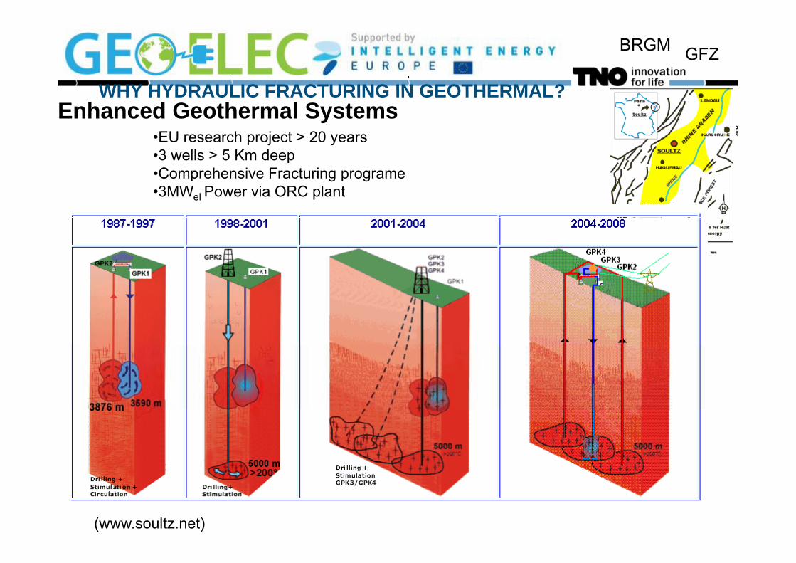
WHY HYDRAULIC FRACTURING IN GEOTHERMAL?
•EU research project > 20 years•3 wells > 5 Km deep
Enhanced Geothermal SystemsWHY HYDRAULIC FRACTURING IN GEOTHERMAL?
•3 wells > 5 Km deep•Comprehensive Fracturing programe•3MWel Power via ORC plant
(www.soultz.net)

BRGM GFZ
WHY HYDRAULIC FRACTURINGIN GEOTHERMAL?
Doublet performance
Fl t Q
E [MWth] = Q*ΔT * CP Tp=70 C Ti=25 C
Flow-rate QΔp
Permeability X thickness
Δp generated by pumpsWhich consume electricity
y
ΔkHQ 2π Which consume electricity
Δp is restricted by safetymeasures⎟⎟
⎠
⎞⎜⎜⎝
⎛+⎟⎟
⎠
⎞⎜⎜⎝
⎛Δ=
SrL
pQ
w
lnμ
Δp at surface does not linearly lead toHigher flow rates (friction in tubes)Viscosity distance
⎠⎝ ⎠⎝ w

BRGM GFZ
Hydraulic fracturing can be considered as reducing skin
Lf = 50mRw = 0.15mS = - ln(0.5*Lf/rw) = -5
⎟⎞
⎜⎛ ⎞⎛
Δ=LkHpQ 2π L=1500m
Improvement Q factor 2
⎟⎟⎠
⎞⎜⎜⎝
⎛+⎟⎟
⎠
⎞⎜⎜⎝
⎛S
rLw
lnμ

BRGM GFZ
Effect of hydraulic fraccing
Doublet Power (MWth) / Costs of Energy (EUR/GJ)
0
0,5
0 5 10 15 20DoubletPower orig.
Costs of1
1,5
2(km)
Costs ofEnergy orig.DoubletPower2
2,5
3Dep
th ( Power
Costs ofEnergy
Transmissivit3,5
4
4,5
yTransmissivity
0 20 40 60 80 100
Tranmissivity (Dm)

BRGM GFZ
Hydraulic fracturing – Types of applications
Tip-Screen-Out fracturing / Frac & PackGoal: Bypass damageTypically in higher-permeability reservoirShort fractureTip-Screen-Out to increase fracture widthTip Screen Out to increase fracture width

Well layout (5-7 km depth) Tensile fraccing
80C240C
400 m

10October 10, 2011
Depth of top Dinantian Carbonates(Geluk, 2007)
Seismic interpretation

BRGM GFZ
[mDm]

BRGM GFZ
Hydraulic fracturing – Applications
Frac & Pack Weak, permeable formations
Stimulating naturally fractured reservoir
Bypass skinSand control
M i H d li F t i
Activate fracture networkE.g. unconventional shale gas
Water injectionMassive Hydraulic Fracturing(EGS, aquifers)
Low-permeability reservoir
Water injectionMaintain injectivityThermal fracturingo pe eab ty ese o
Usually first minifrac testFracture pressure
Leakoff tests, Extended leakofftests
Fracture gradientContainment
Leakoff behavior
Fracture gradientMininum in-situ stress
Waste disposalpDrill cuttingsProduced water

BRGM GFZ
Hydraulic Fracturing – Coupled Processes
BRGM GFZ
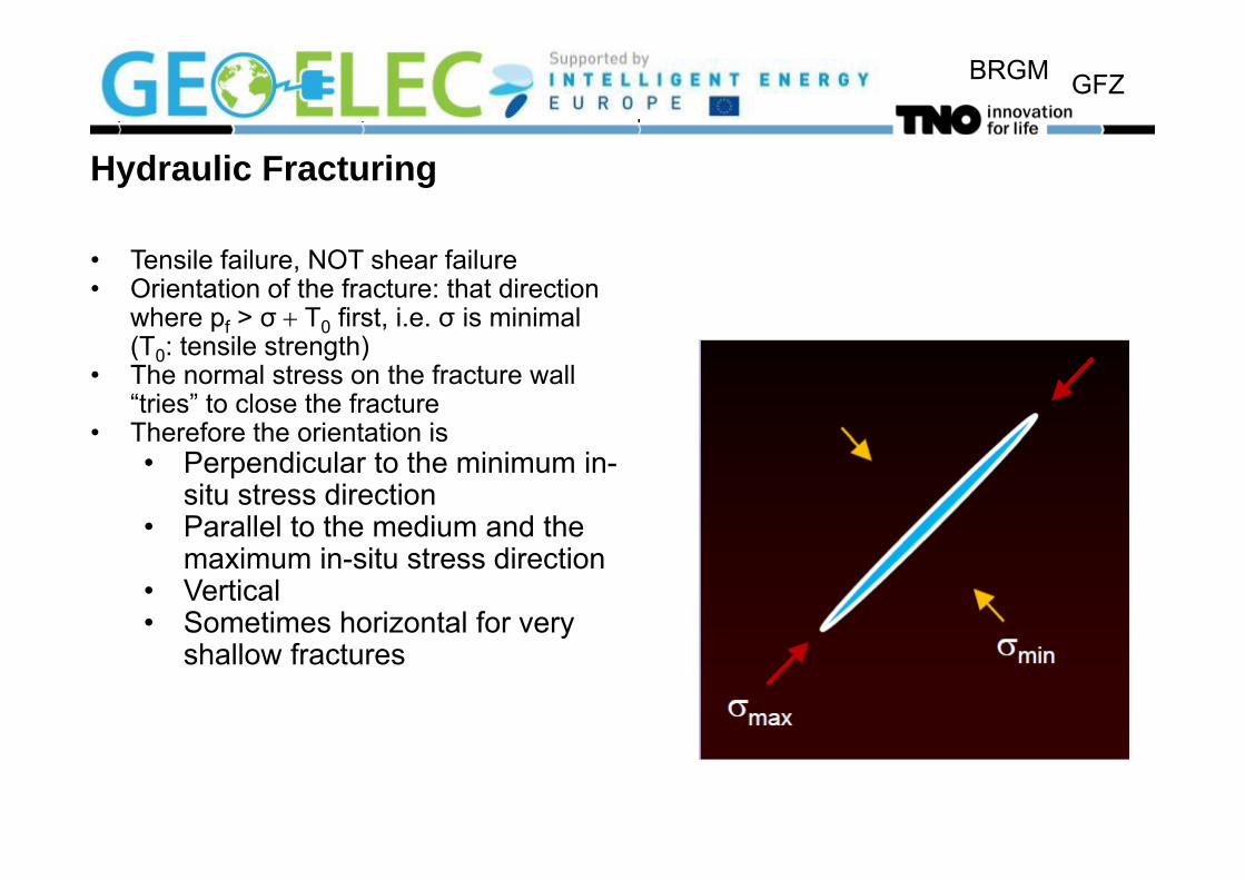
Hydraulic Fracturing
• Tensile failure, NOT shear failure• Orientation of the fracture: that direction
where pf > σ + T0 first, i.e. σ is minimal (T t il t th)(T0: tensile strength)
• The normal stress on the fracture wall “tries” to close the fracture
• Therefore the orientation isTherefore the orientation is• Perpendicular to the minimum in-
situ stress direction• Parallel to the medium and the
maximum in-situ stress direction• Vertical• Sometimes horizontal for very
shallow fractures

BRGM GFZ
Ph i lPhysical process
pf>closure stress(σc ==σh)
Hydraulic fraccinng
S Elastic closureShut-in
Elastic closure
LeakoffPf==σc

BRGM GFZ
Hydraulic fracturing
Water Injection under Fracturing Conditions
Plugging and Channelling in
Fracturing Conditions
Fluid flow in Reservoirg
Fracture
CrackingFluid flow in Fracture
Fracture
ReducedPermeability

BRGM GFZHydraulic fracturing – gas shale learning base
Barnett shaleVery low permeabilityNaturally fractured
Goal: interconnected fracture networkfracture networkWaterfracturingMonitoring

BRGM GFZ
Hydraulic fracturing – Basic concepts
σStress: maximum stress vertical; minimum and medium stresses
σ1
horizontal
Modes of fracturingσ3
Modes of fracturing
σ2
Hydraulic fracturing: Tensile (mode I) – Vertical fracture has least resistance
Mode I: Opening Mode III: TearingMode II: Sliding

BRGM GFZ
Sollicited Induced seismicityEGS operations relies on generating permeability through shear fractures.
Through massive fluid injection typically 50l/s over various daysThrough massive fluid injection typically 50l/s over various days
Basel injection rate (haering, 2008)

BRGM GFZ
H d li F t i th d fi tHydraulic Fracturing – growth and confinement

BRGM GFZ
Hydraulic Fracturing
18000 20 40 60 80
Stress [MPa]Lithography induces contrasts in minimum in-situ stress 1800
2000
2200
in minimum in-situ stressLithgraphic density: 2200 kg / m3
gzz ρσ =ν=2200
2400
2600th [m
]
Fluid density:1000 kg / m3
0.4
ν=2600
2800
3000D
ept
zh σνσ =1
0.3
ν=3000
3200
3400
gzfαρνν
ν
−−
+
−
121
10.4
3400
Poisson’s ratio [-]0 1

BRGM GFZ
Hydraulic Fracturing –Effect of layering confinementEffect of layering, confinement
Layeringσh
y gElasticityStress
hFracture vs timePermeability
Porosityde
pth
injection

BRGM GFZ
H d li f t i ti ( i l )Hydraulic fracturing operations (pinnacle)

BRGM GFZ
How BIG are hydraulic frac jobs
Fracture treatment volumes can be over 10,000 m3
Pump rates can be 100 l/s or more
Proppant placed up to 1 mln kg
Fracture length ranges from 3 to 1500 m
$ $Treatments cost ranges from $5,000 to $5,000,000 USD

BRGM GFZ
Experiments (Fisher, 2010)

BRGM GFZ
Experiments (Fisher, 2010)2010)
Horizontal wellHorizontal well
Planar fracture surface (vertical)

BRGM GFZ
Stress CONTROLS fracture propagation over modulus

BRGM GFZ
Stratigraphic layering (and overpressure) cause fractures to be abruptly blunted
BRGM GFZ
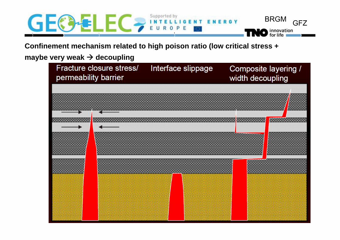
Confinement mechanism related to high poison ratio (low critical stress + maybe very weak decoupling

BRGM GFZ

BRGM GFZ
Multiple fracs:
Store excess volumeStore excess volume• Reduced length
Additional leakoff• Additional fracture faces• May change significantly with time• May change significantly with time
Higher pressure dropg p p• Additional fracture faces
Ti t d ff tTip generated effects• additional stress with shear dilatency
different prop settling/transport

BRGM GFZ
Modelling versus measuring
Fracture growth models
Mapping diagnosticsincomplete physical
understanding
diagnosticsnot predictive
C lib t d d lCalibrated models more realistically predict how fractures will grow forfractures will grow for alternative designs

BRGM GFZ
An example of a model:Effect of Stress Gradient and Stress Contrast
900 400900
950
1000 300
350
400
(m)Shale layer Increased stress
in shale layer1050
1100
1150Dep
th (m
)
150
200
250
ctur
e le
ngth
Fracture height
Fracture length
Δσ = 0 MPaΔσ = 1 MPaΔσ = 2 MPaΔ 3 MP
in shale layer
1150
1200
1250 50
100
150
Frac Δσ = 3 MPa
13000 2000 4000 6000 8000
Time (days)
0

BRGM GFZ
Width and length contours (Δσ = 2 MPa)

BRGM GFZ
What can we measure/ESTIMATE
• Lithology (logs) • Gamma Ray (GR)
• dynamic modulus (E) and• dynamic modulus (E) and • poision ratio (v)
• Micro-seismicity (shear failure only)y ( y)• Stress (special measurements MRX)• Pressure
Tilt t• Tilt meters

BRGM GFZ
P f bl d i i f t tPreferably do a mini-frac test
M i t f d iMore input for design:In-situ stressesFracturing pressures Minifrac test}Fracturing pressures Minifrac testLeakoff behaviour
}ISIP = initial shut –inPressure
Shut-in time

BRGM GFZ
Use pressure to constrain fracs

BRGM GFZStress changes during fracturing

BRGM GFZ
Sometimes model predictions and measurements agree well

BRGM GFZ
But in other cases not

BRGM GFZ
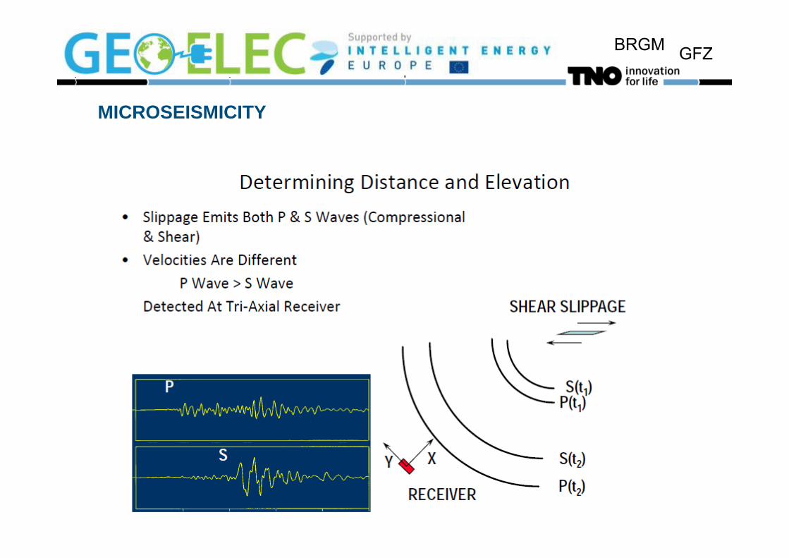
MICROSEISMICITY
BRGM GFZ
MICROSEISMICITY

BRGM GFZ
Microseismic monitoring
• Numerous cases where fracture
grows at or close to microseismic
observation well
• Height can be accurately assessed
• Usually observe fractures following
lithologylithology

BRGM GFZ
Fracture containment AS a conseqence of strength of surrounding layers
Variable containment in shales• Containment (e.g., Barnett)• Bounded by carbonates• Upward growth• Continuous shale• Continuous shale
Faulting effects

BRGM GFZ
Microseismic data and model calibration-cotton valley sst

BRGM GFZ
Offset due to natural fractures and faults

BRGM GFZ
Hydraulic Fracturing in Shale Gas - Observations
No two shales alike. They vary aerially, vertically & along wellbore.
Shale “fabric” differences, in-situ stresses and geologic variances often require stimulation changesoften require stimulation changes.
First need - Identify critical data set y
Second need – never stop learning about the shale.

BRGM GFZ
Natural pathways. Open at 50 to 60% ofOpen at 50 to 60% of rock frac pressure. Open by low viscosity fl id i ifluid invasion. Difficult to prop. DominateDominate Permeability
Natural fracture systems

BRGM GFZ
Coupling betweenCoupling between geomechanics(friction; fault reactivation) and flow behaviour (dual porosity(dual porosity system)

BRGM GFZ
Effect of elastic / plastic behaviourBrittle shales are more easily fracturedSoft material: Healing of fractures
Dynamic E=sonicStatic E=mechanicalexperiment

BRGM GFZ
Re-Fracturing
Th W k B t Wh ?They Work – But Why?Old fractures with gel
Slick water fracturingSlick water fracturing connects to larger part of reservoir
Change of stress orientation

BRGM GFZ
Fracture Network Complexity
Complexity develops if natural fracture system is connected to induced fractureComplexity develops if natural fracture system is connected to induced fracture and openedObserved with microseismic monitoring

BRGM GFZ
P t l tProppant placement
Proppant settles due to low water viscosityyUnpropped fracture part still contributes to flow th h d tthrough propped partDistinction between brittle material (fractures stay)material (fractures stay) and ductile material (fractures heal)

BRGM GFZ
Water Management
Cleanup water produced back early
Use produced water for later fracture treatments
Economic and Ecologic advantages

BRGM GFZ
Interference concerns with groundwater?Not so likely due to excellent vertical confinementNot so likely due to excellent vertical confinement