Embed Size (px)
Citation preview
NASA TECHNICAL NOTE
-/2 <?33
NASA TN D-7H9
F 8 fiI iu
COPY
ELASTOSTATIC STRESS ANALYSISOF ORTHOTROPIC RECTANGULARCENTER-CRACKED PLATES
by George S. Gyekenyesi and Alexander Mendelson
Lewis Research Center
Cleveland, Ohio 44135
NATIONAL AERONAUTICS AND SPACE ADMINISTRATION • WASHINGTON, D. C. • NOVEMBER 1972
https://ntrs.nasa.gov/search.jsp?R=19730004206 2018-08-20T21:43:58+00:00Z
1.
4.
Report No.
NASA TN D-7119Title and Subtitle
2. Government Accession No.
ELASTOSTATIC STRESS ANALYSIS OF ORTHOTROPICRECTANGULAR CENTER- CRACKED PLATES
7. Author(s)
George S. Gyekenyesi and Alexander Mendelson
9.
12.
15.
16.
Performing Organization Name and Address
Lewis Research CenterNational Aeronautics and SpaceCleveland, Ohio 44135
Sponsoring Agency Name and Address
National Aeronautics and SpaceWashington, D. C. 20546
Supplementary Notes
Administration
Administration
3. Recipient's Catalog No.
5. Report DateNovember 1972
6. Performing Organization Code
8. Performing Organization Report No.
E-688910. Work Unit No.
501-22
11. Contract or Grant No.
13. Type of Report and Period Covered
Technical Note14. Sponsoring Agency Code
Abstract
A mapping- collocation method was developed for the elastostatic stress analysis of finite,anisotropic plates with centrally located traction- free cracks. The method essentially consistsof mapping the crack into the unit circle and satisfying the crack boundary conditions exactlywith the help of Muskhelishvili's function extension concept. The conditions on theary are satisfied approximately by applying the
outer bound-method of least- squares boundary collocation.
A parametric study of finite-plate stress intensity factors, employing this mapping- collocationmethod, is presented. It shows the effects of varying material properties, orientation angle,and crack- length-to-plate- width and plate- height- to- plate- width ratios for rectangular ortho-tropic plates under constant tensile and shear loads.
17.
19.
Key Words (Suggested by Author(s) )
Fracture mechanics CracksElasticity PlatesAnisotropy
Security Classif. (of this report)
Unclassified
18. Distribution Statement
Unclassified - unlimited
20. Security Classif. (of this page)
Unclassified21. No. of Pages
32
22. Price*
$3.00
' For sale by the National Technical Information Service, Springfield, Virginia 22151
ELASTOSTATIC STRESS ANALYSIS OF ORTHOTROPIC
RECTANGULAR CENTER-CRACKED PLATES
by George S. Gyekenyesi and Alexander Mendelson
Lewis Research Center
SUMMARY
A mapping-collocation method was developed for the elastostatic stress analysis of"finite, anisotropic plates with centrally located traction-free cracks. The method es-sentially consists of mapping the crack into the unit circle and satisfying the crackboundary conditions exactly with the help of Muskhelishvili's function extension concept.The conditions on the outer boundary are satisfied approximately by applying the methodof least-squares boundary collocation.
A parametric study of finite-plate stress intensity factors, employing this mapping-collocation method, is presented. It shows the effects of varying material properties,orientation angle, and crack-length-to-plate-width and plate-height-to-plate-width ratiosfor rectangular orthotropic plates under constant tensile and shear loads.
INTRODUCTION
Anisotropic materials are frequently applied in present-day structural design, asexemplified in composite materials. Therefore, the problems pertaining to the stressdistribution in finite and quasi-infinite plates of such materials containing cracks are ofimmediate importance. The infinite-plate problems present no difficulty (refs. 1 to 8);however, the problems of finite anisotropic plates with cracks remained fairly neglecteduntil quite recently (refs. 9 to 11).
The mapping-collocation method as applied in this report was developed in refer-ence 10 and parallels Bowie's mapping-collocation technique (ref. 12) for a finite iso-tropic plate with a central traction-free crack.
This report analyzes the effects of varying material properties, orientation angle,and crack-length-to-plate-width and plate-height-to-plate-width ratios on both theopening- and sliding-mode stress intensity factors in a rectangular orthotropic plate
with a centrally located traction-free crack under constant tensile and shear loads.In addition to the parametric investigation, a brief summary of the development of
the mapping-collocation method is presented; however, for a detailed exposition thereader is referred to reference 10.
SYMBOLS
The following list contains the more commonly used symbols and their representa-tive meaning unless otherwise.defined in the text. In general, all symbols are defined
when first introduced.
A.. n complex constant in Laurent series associated with positive ex-
ponent terms
a half-crack length
B, n complex constant in Laurent series associated with negative ex-ponent terms
C-i ij element of elastic compliance matrix
¥+ n modified complex constant associated with positive exponent
terms in Laurent series
*2n n modified complex constant associated with negative exponentterms in Laurent series
^f complex constant depending on material properties\f
<t', <jf^ modified complex constants depending on sum and difference ofA.,j and BJJ, respectively
c half-width of rectangular plate
E...,, Ego Young's moduli of elasticity with respect to coordinate directions
^ln» ^2 ' ^ln' ^2n comPlex quantities utilized in construction of coefficient matrix inleast-squares boundary collocation method
G^2 , shear modulus of an orthotrppic material .
H-pHo . . • nondimensional opening- and sliding-mode stress intensity factors,respectively > ;
h half-height of a rectangular plate
K1,K0 opening-and sliding-mode stress intensity factors, respectivelyA £ t . . - - . . . - . ' - ' /
M total number of collocation points on outer boundary of region withcentral crack
NN, NP truncation numbers on infinite sums associated with negative and posi-tive exponent terms in Laurent series, respectively
T constant shear stress applied to boundary of square platesTV constant tensile stress applied to boundary of rectangular plate
x, y rectangular coordinates
z conventional complex variable
Zp Zg complex variables modified by material properties
6 material orientation angle
£, £k complex variables in parametric planes
vjg Poisson's ratio in an orthotropic material
Mi, Mo Lekhnitskii's material parameters
°xx' CTw' °xv components of stress tensor, rectangular coordinates
<p Airy's stress function
< p j C z ^ ) , ^2^Z2^ complex stress potential functions
BRIEF DESCRIPTION OF MAPPING-COLLOCATION METHOD
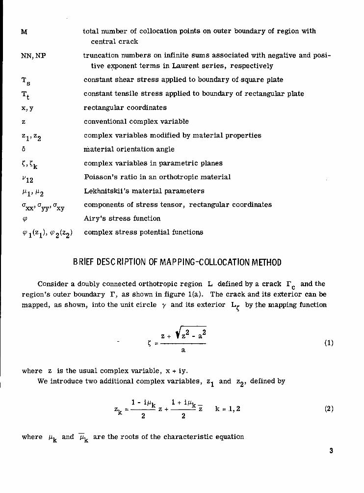
Consider a doubly connected orthotropic region L defined by a crack r and the\s
region's outer boundary T, as shown in figure l(a). The crack and its exterior can bemapped, as shown, into the unit circle y and its exterior L* by the mapping function
+ Vz 2 - a 2
(1)
where z is the usual complex variable, x + iy.We introduce two additional complex variables, Z and Z, defined by
zv= ^z+ Si k = l,2 (2)K 2 2
where JLU and "jiL are the roots of the characteristic equation
22 = 0 (3)
and the C.. are the material compliances appearing in the generalized Hooke's law foran orthotropic material.
The regions L^ with the boundaries T k and IV obtained by the transformation(2) can also be mapped into their respective £k-planes by the mapping functions
ak = 1,2 (4)
as illustrated in figures l(b) and (c).
tyl
^-
_^-
-S
^ '^
LIrcl
^HV
(a)
c = Z l +• ,,31
Vi-/ ^x ?
Region L.
r~7 ?Vzi " a
a
/
/\
Zj-plane
(b) Region Lj.
£-plane
(c) Region L^
Figure 1. - Mapping of doubly connected regions L, Lj, and L2
into their corresponding parametric planes.
The Airy stress function <p (x, y) can be written in terms of two analytic functionsof the complex variables z^ and z2:
<p (x, y) = /^[F^) + F2(z2)] . (5)
With the following definitions :
and
dF
the zero traction conditions on the crack can be satisfied by applying Muskhelishvili'sfunction extension concept across the unit circle (ref. 13). This is accomplished byexpressing one of the unknown complex stress potentials in terms of the other. If
is chosen as
M2 - M2 M2 - M2
the crack boundary conditions will be satisfied for any choice of <P^(Cj ) , provided it isanalytic.
The substitution of expression (6) into the boundary conditions for the outer boundaryof the region results in two conditions given completely in terms of ( ^ ) , cf> ( ? ) , and
The determination of tp i(?i) depends on its form of representation and the satisfac-tion of the boundary conditions on the outer boundary. Specifically, it is assumed that<p i(£, i) can be represented in the form of a truncated Laurent series, such that
NP NN
Eii-axis
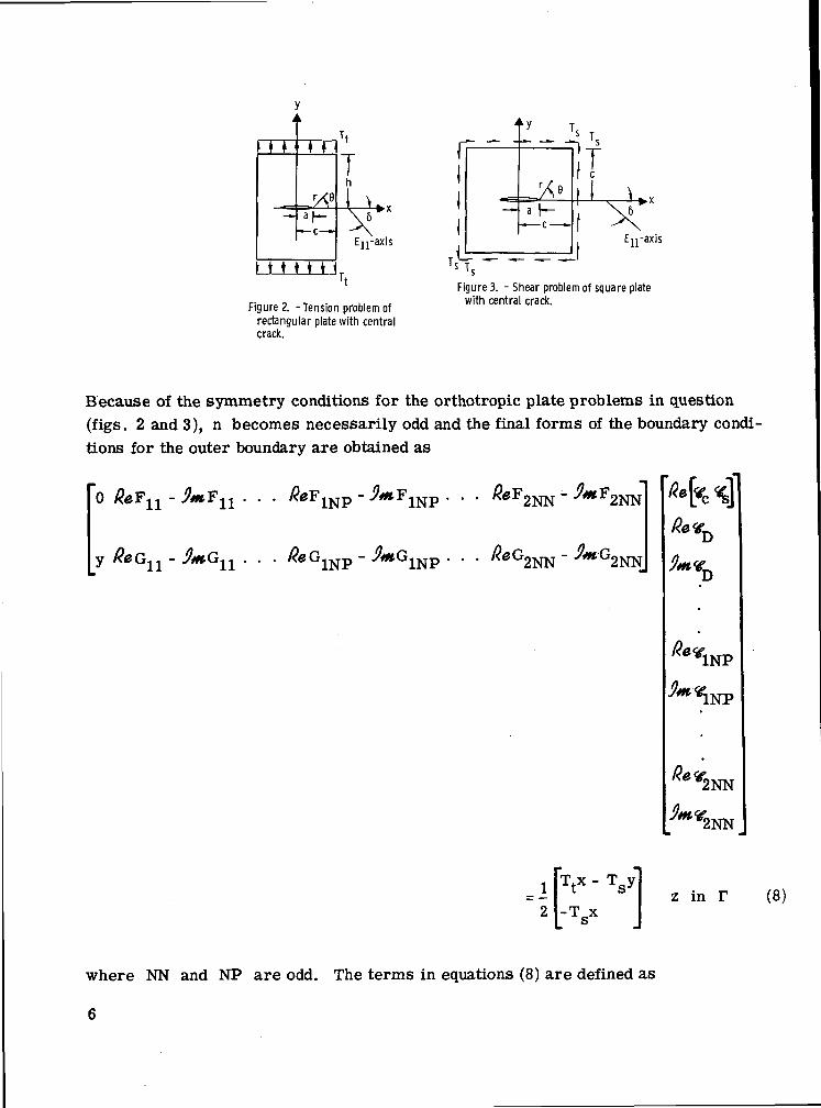
Figure 2. -Tension problem ofrectangular plate with centralcrack.
A
-fc- — •i _
«^
--. 1
r / e
J-t-
iic
\6^\
Ejj-axis
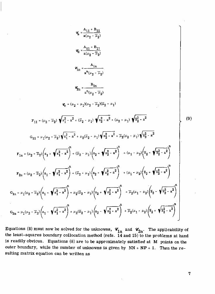
Figure 3. - Shear problem of square platewith central crack.
Because of the symmetry conditions for the orthotropic plate problems in question(figs. 2 and 3), n becomes necessarily odd and the final forms of the boundary condi-tions for the outer boundary are obtained as
z in T (8)
where NN and NP are odd. The terms in equations (8) are defined as
6
a(M2 -
BIn
an(M2 - M2)
(JI -+ 2(9)
Equations (8) must now be solved for the unknowns, <<fln and «2n- The applicability of
the least-squares boundary collocation method (refs. 14 and 15) to the problems at handis readily obvious. Equations (8) are to be approximately satisfied at M points on theouter boundary, while the number of unknowns is given by NN + NP + 1. Then the re-sulting matrix equation can be written as
J* (g _ *£
2MX(NN+NP+1) (NN+NP+l)xl' 2MX1(10)
For the least-squares boundary collocation method, the problem becomes
(11)
where ff* is the desired solution vector.The solution of equation (11) was carried out on a digital computer by declaring all
quantities and operations in double precision and utilizing the Gauss-elimination tech-nique with complete pivoting. It should also be mentioned that the elements of the coef-ficient matrix g were scaled by the devisor
R" =
After the approximate solution vector <€* is obtained, the computation of the stressintensity factors and the stress components is a matter of substitution of the elementsof ¥* into the following expressions:
'1 = Va" e
= --*-&NP
n=3,5,7
(12)
NN(13)
axx = 2*«fe<]+2^«& U>2,2 2 /z2 - a2 /z2 - a2
r Z2 a
NP
/z2 a2Z2 a
/z2 - a2
n=3,5,7
(14)
/z2 - a2
( M - ( M -
/ z 2 - a 2
:+ M2
/z2 a2Z " a
- 2/?e
(15)
n=3,5,7
"=3,5,7 (16)
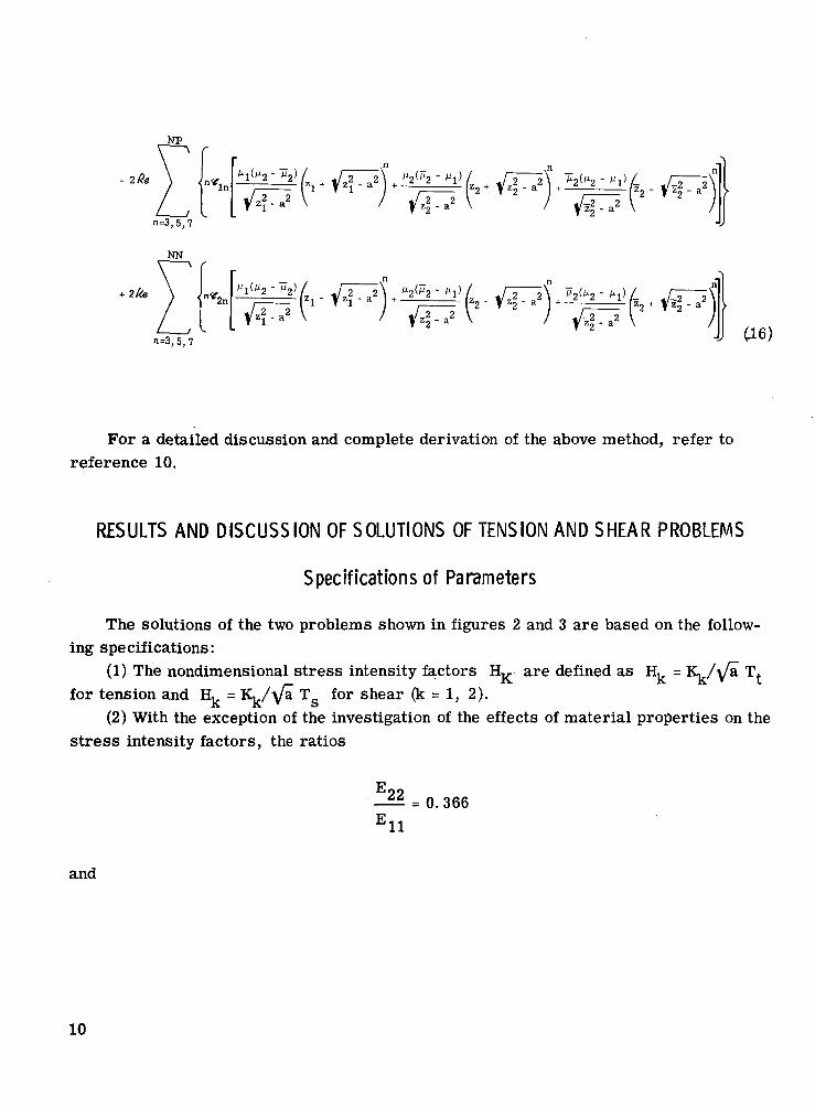
For a detailed discussion and complete derivation of the above method, refer toreference 10.
RESULTS AND DISCUSSION OF SOLUTIONS OF TENSION AND SHEAR PROBLEMS
Specifications of Parameters
The solutions of the two problems shown in figures 2 and 3 are based on the follow-ing specifications:
(1) The nondimensional stress intensity factors HK are defined as EL = K,/ya Tt
for tension and Hk = Kk/\/a Tg for shear (k = 1, 2).(2) With the exception of the investigation of the effects of material properties on the
stress intensity factors, the ratios
E
J22
11- 0.366
and
10
= 0.257
were used throughout the entire analysis. These ratios correspond to the properties offiberglass .
(3) In studying the effects of varying material properties on the stress intensity fac-tors in both the tension and shear problems, the following parameter ranges were con-sidered:
0. 05 <
Eon
0. 001 == - —
(4) In studying the effects of varying plate aspect ratio h/c and crack-length-to-plate-width ratio a/c on the stress intensity factors in the tension problem, the param-eter ranges were chosen as follows:
0.25 <-^ < 133c
6 = 4 5 °
(5) The effects of variation of the orientation angle 6 were also analyzed for boththe tension and shear problems, considering the following parameter ranges:
E-6889 11
c 3
0° < 5 < 90°
Examination of Mapping-Collocation Method
The available results which can be used to check the accuracy of this method arethose for centrally cracked infinite plates (refs. 1 and 3) and the results of Kobayashi,Isida, and Sawyer (refs. 16 to 18) for finite isotropic rectangular plates. In order togain a certain degree of confidence in the mapping- collocation method, both the resultsfor the infinite orthotropic and finite isotropic plates were verified.
The first verification is obtained by making the plate dimensions large compared tothe crack length.
This resulted in Hj = 1.0000 and H2 = 0.0000. The corresponding analytical re-sults for an infinite plate are Hj = 1 and Hg = 0. It was, however, also noted thatthe satisfaction of the stress boundary conditions markedly improved with the use ofmore and more terms in the Laurent series expansion of <p^-^). Thus, the results ofthe infinite plates were verified for both the tension and shear problems.
The verification of Kobayashi 's, Isida's, and Sawyer's opening-mode stress inten-sity factors for various finite isotropic rectangular plates in tension was carried out bysetting the ratios
E22 _
and
12
The value of the orientation angle had no influence on the results. The cases consideredare shown in table I, where the various stress intensity factors are tabulated and canreadily be compared with each other. As can be seen from table I, agreement with theknown results is excellent.
In order to economize the mapping-collocation method with regard to the use of thenumber of terms in the Laurent series expansion of < j0 j (?]_), two different truncationnumbers NN and NP were assigned as limits of the sums in the various expressions.The numbers NN and NP are odd for orthotropic materials and correspond to thenumber of the negative and positive exponent terms in the Laurent series expansion ofthe stress potential function <pj (? j ) . Upon investigating various NN/NP ratios for thefinite plate problems, it was found that a NN/NP ratio of 5/3 resulted in fairly fast con-vergence with rather well-satisfied boundary conditions. This NN/NP ratio was re-tained throughout the whole investigation of the problems given in figures 2 and 3.
One of the most important indications of the degree of accuracy of the solutions ob-tained by the mapping-collocation method comes from the examination of the boundarystress between collocation points. Since the least-squares method of collocation resultsin the satisfaction of the boundary conditions only in the approximate sense, the magni-tude and frequency of oscillations of the boundary stresses serve as an indicator to the"exactness" of the solution of the stress boundary-value problem. Thus, in each case,the boundary stresses were also examined. For example, in the case of a square platein tension with a/c = 2/3 and 6 = 45°, the largest error in the boundary stresses wasfound to be about 4 percent and it occurred in a sudden manner at the corners of theplate.
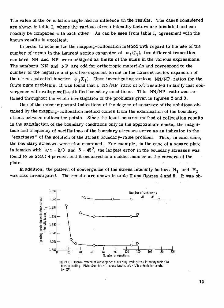
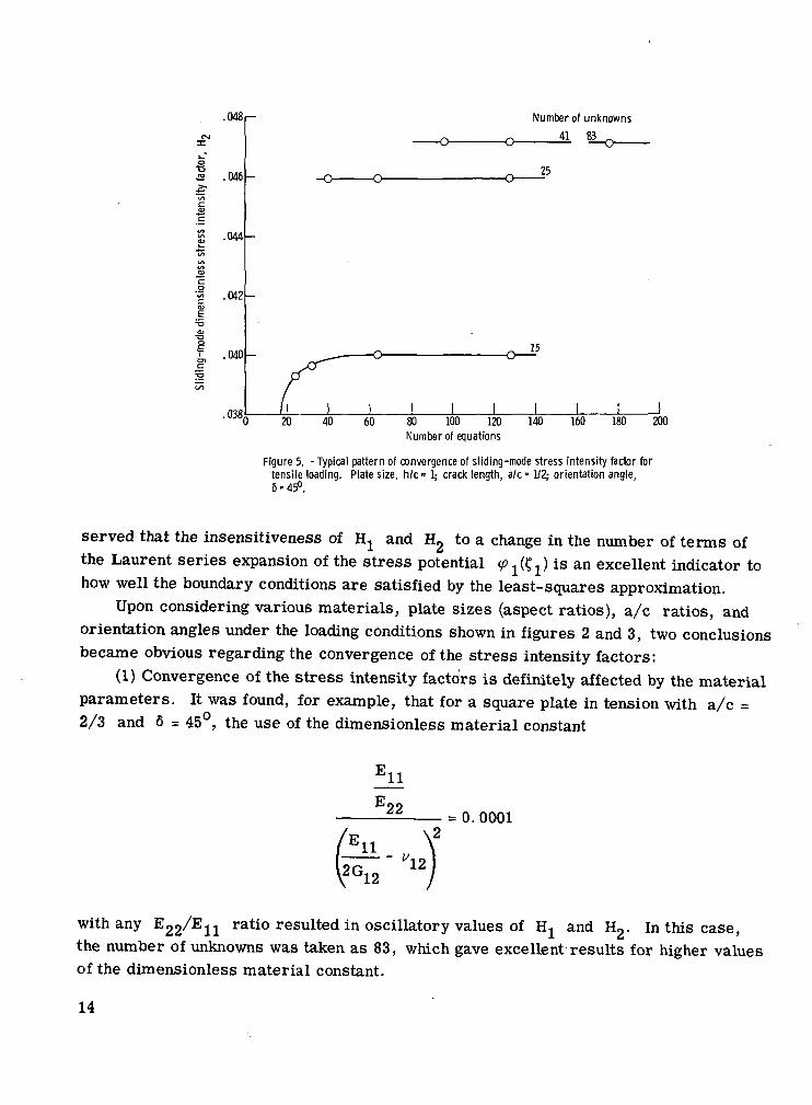
In addition, the pattern of convergence of the stress intensity factors H, and H2
was also investigated. The results are shown in table n and figures 4 and 5. It was ob-
Ifa.o
1.358
1.356
1.354
1.352
1.350
1.348
1.346
1.344
Number of unknowns
41 83
25
15
20 40 60 80 100 120 140Number of equations
160 180 200
Figure 4. - Typical pattern of convergence of opening-mode stress intensity factor fortensile loading. Plate size, h/c = 1; crack length, a /c= 1/2; orientation angle,6=45°.
13
.048
J2 .046
.044
.042
.040
.038,
Number of unknowns41 83
25
15
20 40 60 80 100 120
Number of equations140 160 180 200
Figure 5. - Typical pattern of convergence of sliding-mode stress intensity factor fortensile loading, Plate size, h/c= 1; crack length, a/c= 1/2; orientation angle,6 = 45°.
served that the insensitiveness of Hj and H2 to a change in the number of terms ofthe Laurent series expansion of the stress potential ^1(?1) is an excellent indicator tohow well the boundary conditions are satisfied by the least-squares approximation.
Upon considering various materials, plate sizes (aspect ratios), a/c ratios, andorientation angles under the loading conditions shown in figures 2 and 3, two conclusionsbecame obvious regarding the convergence of the stress intensity factors:
(1) Convergence of the stress intensity factors is definitely affected by the materialparameters. It was found, for example, that for a square plate in tension with a/c =2/3 and 6 = 45°, the use of the dimensionless material constant
E11J22 = 0.0001
with any E^/Ejj ratio resulted in oscillatory values of Hj and Hg. In this case,the number of unknowns was taken as 83, which gave excellent results for higher valuesof the dimensionless material constant.
14
(2) Convergence of the stress intensity factors is also affected by the a/c ratios.For a square plate in tension with
Eon
^ = 0.257
and with E^O/EU = 0.366, a/c = 0. 9, and 6 = 45° with the use of 83 unknowns, it wasfound that the boundary conditions were rather badly satisfied. The method probablyresulted in unconverged stress intensity factors. For smaller a/c ratios, well-converged values of H, and Hg were obtained.
SOLUTION OF TENSION PROBLEMS OF ORTHOTROPIC
RECTANGULAR PLATE WITH CENTRAL CRACK
The consideration of the tension problem, that is, when the constant boundarystress is applied in the y-direction (fig. 2), resulted in various parametric studies in-volving material properties, a/c ratios, h/c ratios, and orientation angles.
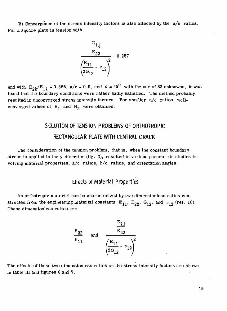
Effects of Material Properties
An orthotropic material can be characterized by two dimensionless ratios con-structed from the engineering material constants EJJ , Ego? GJQ, and v*n (ref. 10).These dimensionless ratios are
fii
^2 and ?22
The effects of these two dimensionless ratios on the stress intensity factors are shownin table ni and figures 6 and 7.
15
ill.'12 '12
Figure 6. - Effects of material properties on opening-modestress intensity factor for tensile loading: Plate size,-h/c= 1; crack length, a/c= 2/3; orientation angle,5=45°.
1 -.5
-.4
7. J>
.9 i-"
[ & -.2
\ -.1
°oT
Weaklyorthotropicmaterial-^
I.1 1
EU/E22
2G 12J\2
0.05
10 100
Figure 7. - Effects of material properties on sliding-modestress intensity factor for tensile loading. Plate size,h/c = 1; crack length, a/c= 2/3; orientation angle,6=45°.
Figure 6 demonstrates the effects of the dimensionless material ratios on theopening-mode stress intensity factor, while figure 7 shows the sliding-mode stress in-tensity factor as a function of these two ratios. Figure 6 shows that, as the F^/Ejiratio decreases, the opening-mode dimensionless stress intensity factor H, increasesin value and that, for a fixed value of this ratio, the stress intensity factor exhibits aminimum value.
Figure 7 shows the interesting result that there exists a sliding-mode stress inten-sity factor for the case of a pure tensile load, contrary to the results for an infinite orisotropic plate. This results strictly from the orthotropy of the material and the finite-ness of the plate dimensions. It may be noted that the maximum magnitude of thesliding-mode stress intensity factor shown in figure 7 is about 14 percent of the opening-mode stress intensity factor for the same ^^E ratio-
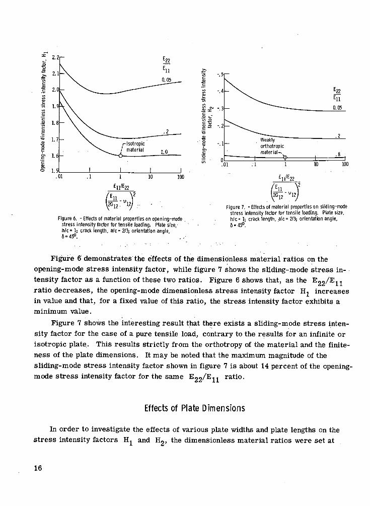
Effects of Plate Dimensions
In order to investigate the effects of various plate widths and plate lengths on thestress intensity factors H and H, the dimensionless material ratios were set at
16
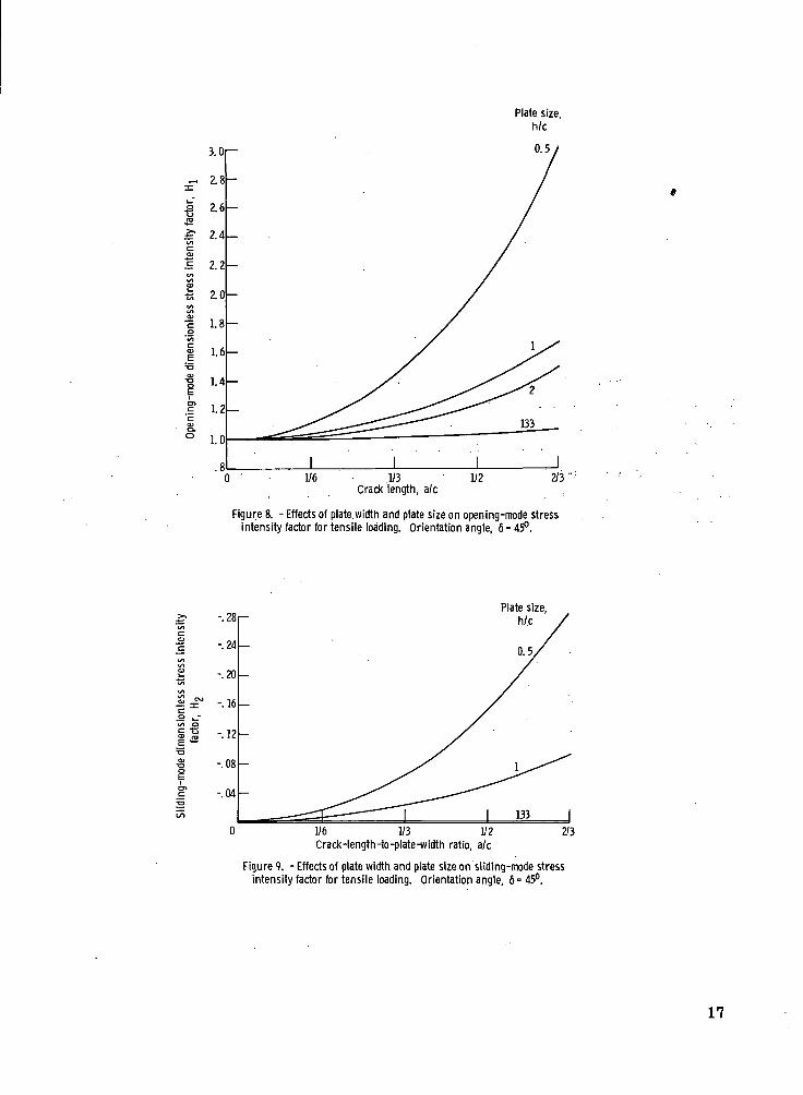
Plate size,h/c
•c•2.£•
s.o
1/6 1/3Crack length, ale
Figure 8. - Effects of plate width and plate size on opening-mode stressintensity factor for tensile loading. Orientation angle, 6=45°.
-.28
-.24
-.20
-.16
-.12
-.08
-.04
Plate size,h/.c
1/6 1/3 1/2Crack-length-to-plate-width ratio, a/c
2/3
Figure 9. - Effects of plate width and plate size on sliding-mode stressintensity factor for tensile loading. Orientation angle, 6= 45°.
17
E22 = 0. 366 andE 11
n22 = 0.257
- v12
with an orientation angle 6 = 45 . These ratios correspond approximately to fiber-
glass properties. The results are shown in table IV and figures 8 and 9.
Effects of Orientation Angle and Crack Length
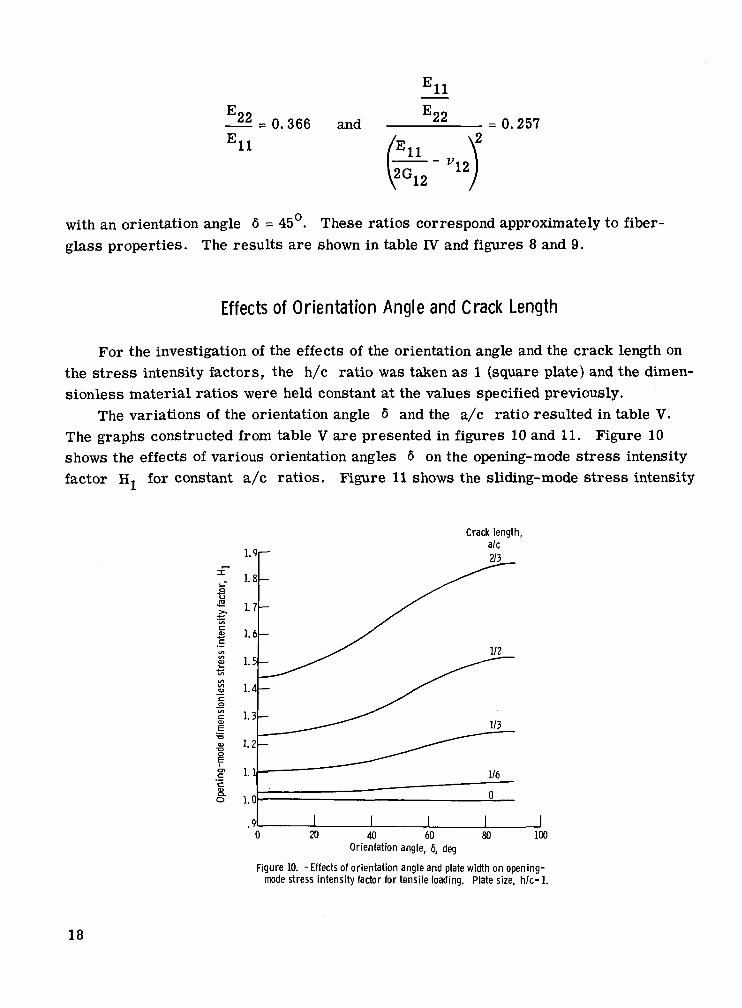
For the investigation of the effects of the orientation angle and the crack length onthe stress intensity factors, the h/c ratio was taken as 1 (square plate) and the dimen-sionless material ratios were held constant at the values specified previously.
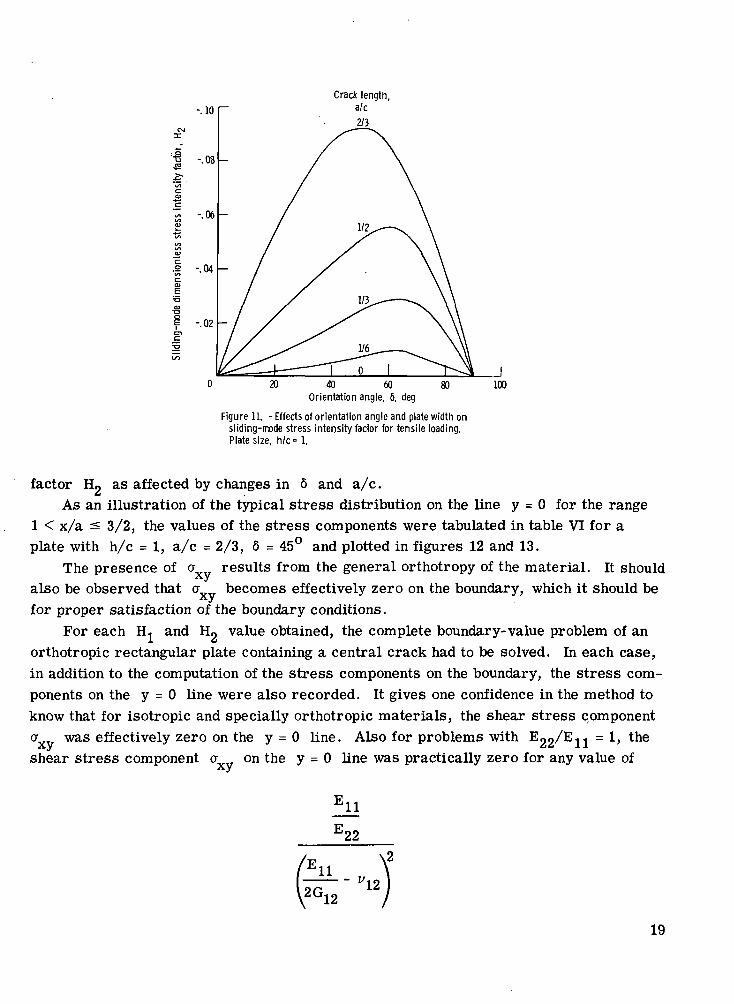
The variations of the orientation angle 6 and the a/c ratio resulted in table V.The graphs constructed from table V are presented in figures 10 and 11. Figure 10shows the effects of various orientation angles 6 on the opening-mode stress intensityfactor H« for constant a/c ratios. Figure 11 shows the sliding-mode stress intensity
Crack length,a/c2/3
20 40 60Orientation angle, 6, deg
100
Figure 10. - Effects of orientation angle and plate width on opening-mode stress intensity factor for tensile loading. Plate size, h/c= 1.
18
Crack lengtha/c2/3
20 40 60Orientation angle, 6, deg
100
Figure 11. - Effects of orientation angle and plate width onsliding-mode stress intensity factor for tensile loading.Plate size, h/c= 1.
factor Hg as affected by changes in 6 and a/c.As an illustration of the typical stress distribution on the line y = 0 for the range
1 < x/a ^ 3/2, the values of the stress components were tabulated in table VI for aplate with h/c = 1, a/c = 2/3, 6 = 45° and plotted in figures 12 and 13.
The presence of a results from the general orthotropy of the material. It shouldalso be observed that a becomes effectively zero on the boundary, which it should befor proper satisfaction of the boundary conditions.
For each H.. and Hg value obtained, the complete boundary-value problem of anorthotropic rectangular plate containing a central crack had to be solved. In each case,in addition to the computation of the stress components on the boundary, the stress com-ponents on the y = 0 line were also recorded. It gives one confidence in the method toknow that for isotropic and specially orthotropic materials, the shear stress component
°xv was effectively zero on the Y = 0 line- Also for problems with E22/En = *> tne
shear stress component a on the y = 0 line was practically zero for any value of
EUE22
11 - v12
19
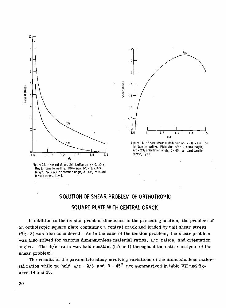
Figure 13. - Shear stress distribution on y = 0 , x>a linefor tensile loading. Plate size, h/c = 1; crack length,a/c= 2/3; orientation angle, 6= 45°; constant tensilestress, Tt • 1.
Figure 12. - Normal stress distribution on y = 0, x> aline for tensile loading. Plate size, h/c • 1; cracklength, a/c- 2/3; orientation angle, 6= 45"; constanttensile stress, t{° 1.
SOLUTION OF SHEAR PROBLEM OF ORTHOTROPIC
SQUARE PLATE WITH CENTRAL CRACK
In addition to the tension problem discussed in the preceding section, the problem ofan orthotropic square plate containing a central crack and loaded by unit shear stress(fig. 3) was also considered. As in the case of the tension problem, the shear problemwas also solved for various dimensionless material ratios, a/c ratios, and orientationangles. The h/c ratio was held constant (h/c = 1) throughout the entire analysis of theshear problem.
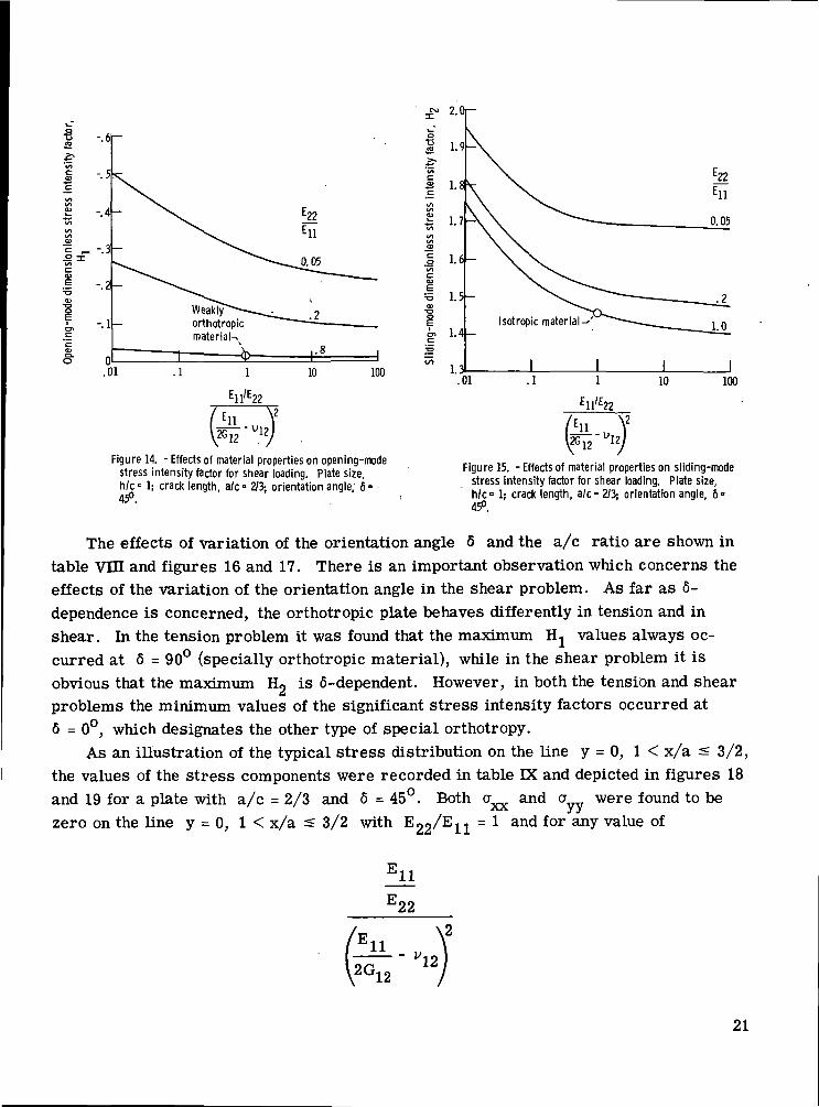
The results of the parametric study involving variations of the dimensionless mater-ial ratios while we held a/c = 2/3 and 6 = 45° are summarized in table VII and fig-ures 14 and 15.
20
1 -.6
*t^
| --5
<S>(/>
2 -.4t/tI/IVl^--3wiC<u.§ - 2•oOJ
!, -.1
22
22
Weaklyorthotropicmaterial^
.01 .1 10 100
Ell'E22
ill2012
V12
Figure 14. - Effects of material properties on opening-modestress intensity factor for shear loading. Plate size,h/c= lj crack length, a/c- 2/3; orientation angle, 6 =45°.
Figure 15. -Effects of material properties on sliding-modestress intensity factor for shear loading. Plate size,h/c= 1; crack length, a/c= 2/3; orientation angle, 6-
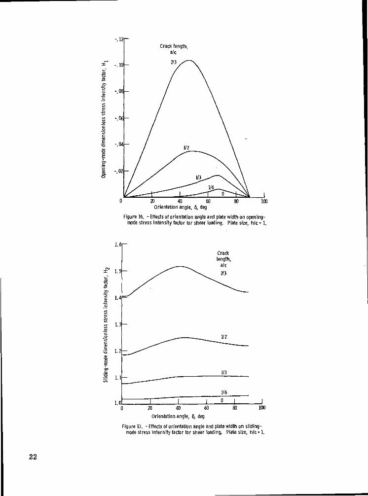
The effects of variation of the orientation angle 6 and the a/c ratio are shown intable VIH and figures 16 and 17. There is an important observation which concerns theeffects of the variation of the orientation angle in the shear problem. As far as 6-dependence is concerned, the orthotropic plate behaves differently in tension and inshear. In the tension problem it was found that the maximum Hj values always oc-curred at 6 = 90° (specially orthotropic material), while in the shear problem it isobvious that the maximum Hg is 6-dependent. However, in both the tension and shearproblems the minimum values of the significant stress intensity factors occurred at6 = 0°, which designates the other type of special orthotropy.
As an illustration of the typical stress distribution on the line y = 0, 1 < x/a s 3/2,the values of the stress components were recorded in table IX and depicted in figures 18and 19 for a plate with a/c = 2/3 and 6 = 45°. Both cr and a were found to beAA yyzero on the line y = 0, 1 < x/a < 3/2 with ^22^11 = * and for any value of
11
22
'iiG12
- v12
21
c.2
S.o
-.10
-.08-
-.06-
-.04
-.021
Crack length,a/c
20 40 60Orientation angle, 6, deg
100
Figure 16. - Effects of orientation angle and plate width on opening-mode stress intensity factor for shear loading. Plate size, We - 1.
0 20 40 60
Orientation angle, 6, deg
Figure IV. - Effects of orientation angle and plate width on sliding-mode stress intensity factor for shear loading. Plate size, h/c • 1.
22
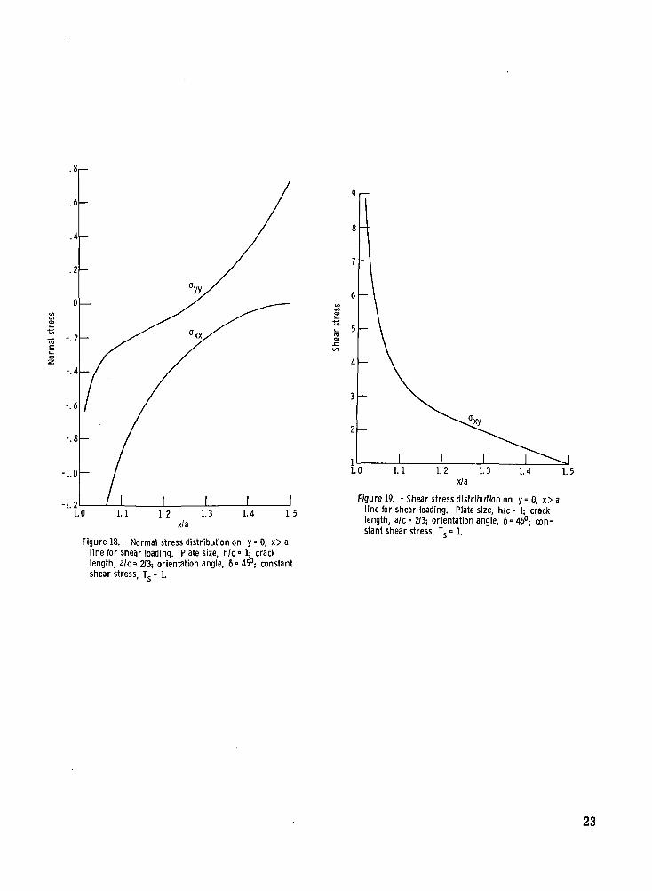
Figure 18. -Normal stress distribution on y = 0 , x> aline for shear loading. Plate size, h/c- 1; cracklength, a/c= 2/3; orientation angle, 6° 4?; constantshear stress, Ts= 1.
Figure 19. - Shear stress distribution on y=0, x> aline for shear loading. Plate size, h/c = 1; cracklength, a/c° 2/3; orientation angle, 6=45°; con-stant shear stress, Ts = 1.
23
The special cases of isotropy and special orthotropy resulted also in zero values for thenormal stresses a and a on the y = 0, 1 < x/a =s 3/2 line.AA yy
CONCLUDING REMARKS
The mapping-collocation method as developed in reference 10 was applied to a largenumber of rectangular orthotropic plate problems in order to study the effects of vary-ing material properties, orientation angles, and crack-length-to-plate-width a/c andplate-height-to-plate-width h/c ratios on the stress intensity factors for both tensileand shear loadings.
A natural extension of the mapping-collocation method as applied to finite ortho-tropic regions with centrally located traction-free cracks would be to consider variousshapes for the inner boundary. For example, triangular, rectangular, and ellipticalboundaries could be specified by a single general Schwarz-Christoffel transformationand mapped into the unit circle. This possibility would require further research as tothe accuracy of the method when it is applied to various types of doubly connected re-gions.
Another direction of research presents itself in the consideration of a more detailedparametric study of the effects of dimensionless material constants, orientation angles,a/c ratios, and h/c ratios on the stress intensity factors. It is a possibility that, forcertain parameter ranges, "practical forms" of expressions could be obtained for theapproximation of the stress intensity factors. These forms would result from curvefitting the various parametric data.
Lewis Research Center,National Aeronautics and Space Administration,
Cleveland, Ohio, September 21, 1972,501-22.
REFERENCES
1. Lekhnitskii, S. G. (P. Fern, trans.): Theory of Elasticity of an Anisotropic ElasticBody. Holden-Day, Inc., 1963.
2. Lekhnitskii, S. G. (Elbridge Z. Stowell, trans.): Anisotropic Plates. AmericanIron and Steel Institute, 1956.
3. Savin, G. N. (Eugene Gros, trans.): Stress Concentration Around Holes. Per-gamon Press, 1961.
24
4. Savin, G. N.: Stress Distribution Around Holes. NASA TT F-607, 1970.
5. Green, A. E.; and Zerna, W.: Theoretical Elasticity. Seconded., Oxford Univer-sity Press, 1968.
6. Milne-Thomson, L. M.: Plane Elastic Systems. Seconded., Springer-Verlag, 1968.7. Ang, D. D.; and Williams, M. L.: Combined Stresses in an Orthotropic Plate Having
a Finite Crack. J. Appl. Mech., vol. 28, no. 3, Sept. 1961, pp. 372-378.
8. Mendelson, Alexander; and Spero, Samuel W.: Elastic Stress Distribution in aFinite-Width Orthotropic Plate Containing a Crack. NASA TN D-2260, 1964.
9. Gandhi, Kami R.: Analysis of an Inclined Crack Centrally Placed in an OrthotropicRectangular Plate. Rep. AMMRC-TR-71-31, Army Materials and Mechanics Re-search Center (AD-730911), Aug. 1971.
10. Gyekenyesi, George S.: Elastostatic Stress Analysis of Finite Anisotropic Plateswith Centrally Located Traction-Free Cracks. Ph.D. Thesis, Michigan StateUniversity, 1972.
11. Bowie, O. L.; and Freese, C. E.: Central Crack in Plane Orthotropic RectangularSheet. Int. J. Fracture Mech., vol. 8, no. 1, Mar. 1972, pp. 49-58.
12. Bowie, Oscar L.; and Neal, Donald M.: A Modified Mapping-Collocation Techniquefor Accurate Calculation of Stress Intensity Factors. Rep. AMMRC-TR-69-28,Army Materials and Mechanics Research Center (AD-702248), Nov. 1969.
13. Muskhelishvili, N. I. (J. R. M. Radok, trans.): Some Basic Problems of the Mathe-matical Theory of Elasticity. P. Noordhoff, Ltd., 1953.
14. Altmann, S. L.: The Cellular Method for a Close-Packed Hexagonal Lattice. II.The Computations: A Program for a Digital Computer and an Application to Zir-conium Metal. Proc. Roy. Soc. (London), Ser. A, vol. 244, no. 1237, Mar. 11,1958, pp. 153-165.
15. Hulbert, Lewis E.: The Numerical Solution of Two-Dimensional Problems of theTheory of Elasticity. Ph.D. Thesis, Ohio State University, 1963.
16. Kobayashi, A. S.; Cherepy, R. D.; and Kins el, W. C.: A Numerical Procedurefor Estimating the Stress Intensity Factor of a Crack in a Finite Plate. J. BasicEng., vol. 86, no. 4, Dec. 1964, pp. 681-684.
17. Isida, M.; and Itagoki, Y.: Stress Concentration at the Tip of a Central TransverseCrack in a Stiffened Plate Subjected to Tension. Proceedings of the Fourth U.S.National Congress of Applied Mechanics. Vol. 2, ASME, 1962.
18. Sawyer, Stephen G.: A Stress Intensity Factor Approach to the Analysis of Inter-facial Cracks in Fiber Reinforced Composite Materials. Ph.D. Thesis, Carnegie-Mellon University, 1969.
25
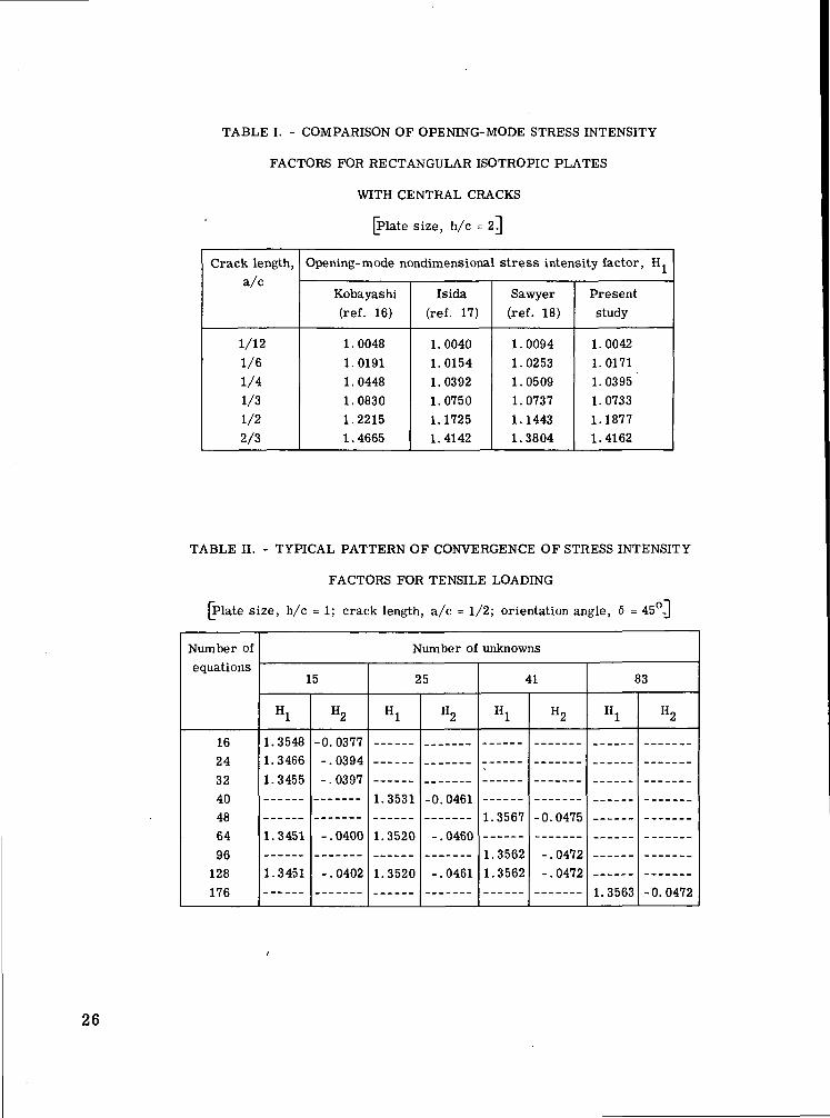
TABLE I. - COMPARISON OF OPENING-MODE STRESS INTENSITY
FACTORS FOR RECTANGULAR ISOTROPIC PLATES
WITH CENTRAL CRACKS
[Plate size, h/c = 2^
Crack length,a/c
1/12
1/61/4
1/31/22/3
Opening-mode nondimensional stress intensity factor, H^
Kobayashi(ref. 16)
1 . 00481.01911.04481.08301.22151 . 4665
Isida(ref. 17)
1.00401.01541.03921.07501.17251.4142
Sawyer(ref. 18)
1.00941.02531.05091.07371.14431.3804
Presentstudy
1.00421.01711.03951.07331.18771.4162
TABLE II. - TYPICAL PATTERN OF CONVERGENCE OF STRESS INTENSITY
FACTORS FOR TENSILE LOADING
(Plate size, h/c = 1; crack length, a/c = 1/2; orientation angle, 6 = 45°J
Number ofequations
16243240486496
128176
Number of unknowns
15
Hl
1.35481.34661.3455
1.3451
1.3451
H2
-0.0377-.0394-.0397
- . 0400
- . 0402
25
Hl
1.3531
1.3520
1.3520
H2
-0.0461
- . 0460
-.0461
41
Hl
1.3567
1.35621.3562
H2
-0.0475
-.0472-.0472
83
Hl
1.3563
H2
-0.0472
26
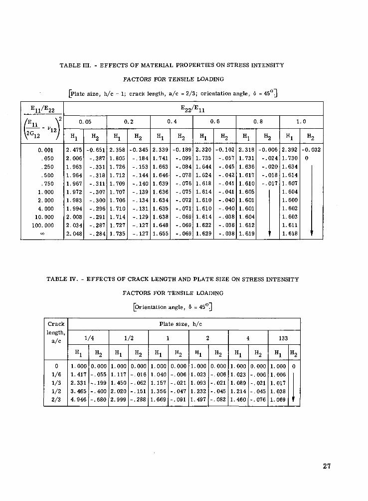
TABLE III. - EFFECTS OF MATERIAL PROPERTIES ON STRESS INTENSITY
FACTORS FOR TENSILE LOADING
[Plate size, h/c = 1; crack length, a/c = 2/3; orientation angle, 6 = 45orj
E11/E22
/F \2
I11 r \Ur 12
\2G12 /
0.001
.050
.250
.500
.750
1.0002.000
4.00010. 000
100. 000OO
E22/E11
0.05
Hl
2.475
2.006
1.963
1.9641.967
1.972
1.9831.9942.008
2.0342.048
H2
-0.651
-.387
-.331-.318
-.311-.307
-.300
-.296-.291-.287
-.284
0.2
Hl
2.358
1.805
1.7261.712
1.7091.707
1.7061.7101.7141.727
1.735
H2
-0.345
-.184
-.153-.144
-.140-.139-.134
-.131-.129
-.127
-.127
0.4
Hl
2.339
1.741
1.6631.646
1.6391.6361.6341.6351.638
1.648
1.655
H2
-0.189
-.099
-.084-.078
-.076-.075-.072-.071
-.069-.069
-.069
0.6
Hl
2.320
1.735
1.644
1.6241.618
1.614
1.6101.6101.6141.622
1.629
H2
-0.102
-.057
-.045
-.042-.041
-.041-.040
-.040-.038
-.038
-.038
0.8
Hl
2.318
1.731
1.6361.617
1.6101.605
1.6011.6011.6041.612
1.619
H2
-0.006
-.024
-.020
-.018-.017
1
1.0
Hl
2.392
1.730
1.634
1.6141.607
1.6041.6001.602
1.6031.6111.618
H2
-0.032
0
TABLE IV. - EFFECTS OF CRACK LENGTH AND PLATE SIZE ON STRESS INTENSITY
FACTORS FOR TENSILE LOADING
[Orientation angle, 6 = 45°J
Crack
length,
a/c
01/6
1/3
1/22/3
Plate size, h/c
1/4
Hl
1.0001.417
2.3313.4654.946
H2
0.000-.055
-.199
-.400-.680
1/2
Hl
1.0001.117
1.450
2.0202.999
H2
0.000
-.016-.062-.151-.288
1
Hl
1.000
1.0401.157
1.3561.669
H2
0.000
-.006-.021-.047
-.091
2
Hl
1.000
1.0231.0931.2321.497
H2
0.000
-.006-.021
-.045-.082
4
Hl
1.000
1.0231.0891.2141.460
H2
0.000-.006-.021
-.045-.076
133
Hl
1.0001.0061.017
1.0381.069
H2
0
f
27
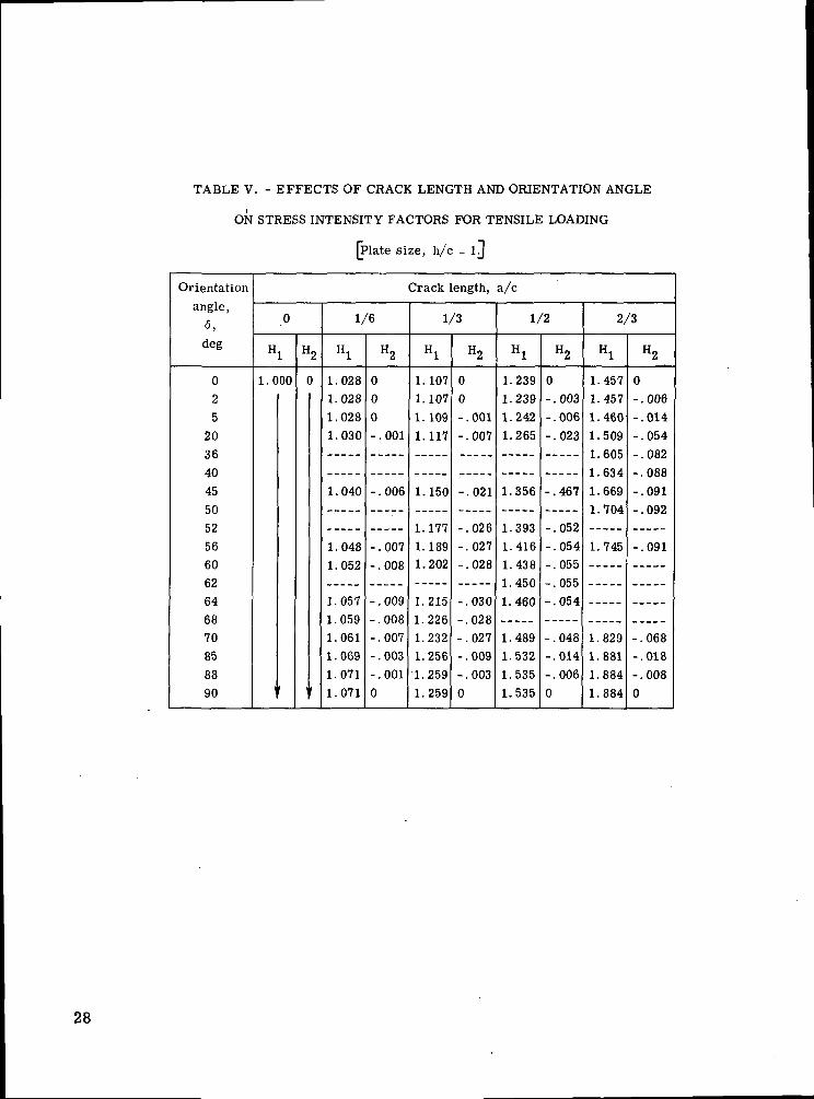
TABLE V. - EFFECTS OF CRACK LENGTH AND ORIENTATION ANGLE
ON STRESS INTENSITY FACTORS FOR TENSILE LOADING
[Plate size, h/c = ij
Orientationangle,
5,deg
025
20Tfi
40
4550R9
56fin62
64fiQ
7085
8890
H
1.0
'
0
1
00
H
(
1
2
)
I/
Hl
1.0281.028
1.028
1.030
1.040
1.0481 HR9
1 057i 059
1.061
1.0691.071
1.071
'6
H2
00
0
-.001
-.006
-.007nno
- 009- 008
-.007
-.003
-.001
0
Crack
1,
Hl
1.1071.107
1.109
1.117
1.150
1 1 11
1.1891 202
1 2151 99fi
1.232
1.256
1.2591.259
ength,
/3
H2
0
0-.001
-.007
-.021
f!9fi
-.027028
- 030- OPS
-.027-.009-.0030
a/c
I/
Hl
1.2391.2391.2421.265
1.356
1 ^Q1}
1.4161 4Tfi
1.4501 460
1.4891.532
1.5351.535
'2
H2
0-.003-.006
-.023
-.467
n59
-.054- 055
-.055
- 054
-.048-.014
-.006
0
2/
Hl
1.4571.457
1.460
1.5091 fiflR
1 634
1.669
1 704
1.745
1.829
1.8811.884
1. 884
'3
H2
0-.006
-.014
-.054- nfi?
- 088-.091- 092
-.091
-.068-.018
-.008
0
28
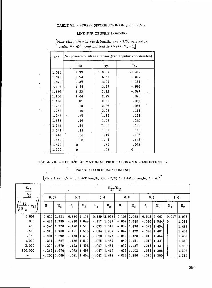
TABLE VI. - STRESS DISTRIBUTION ON y = 0, x > a
LINE FOR TENSILE LOADING
[Plate size, h/c = 1; crack length, a/c = 2/3; orientationangle, 5 = 45°; constant tensile stress, T^. = ij
x/a
1.0161.0461.0761.1061.1361.1661.1961.2281.2581.2881.3181.3481.3741.4101. 4401.4701.500
Components of stress tensor (rectangular coordinates)
axx
7.333.542.371.741.331.04.81.63.49.37.26.18.11.06.03
00
V
9.595.534.273.583.122.772.502.262.051.861.671.501.331.171.01.84.68
CTxy
-0.482-.227-.131-.069-.021 .
.020
. 055
. 085. .111
.131
.146
.153
.150
.136
.108
.0630
TABLE VII. - EFFECTS OF MATERIAL PROPERTIES ON STRESS INTENSITY
FACTORS FOR SHEAR LOADING
[Plate size, h/c = 1; crack length, a/c = 2/3; orientation angle, 6 = 45°J
-iiE22
/Ell \2
Ur l l z)\2G12 /
0.001.050.250.500.750
1.0002.000
100. 000OO
T7 /pE22/E11
0 05
Hl
-0.629-.424-.345-.315-.301-.291-.270-.215-.209
H2
2.2311.7991.7201.7001.6921.6871.6791.6701.669
0 2
Hl
-0.330-.216-.170-.151-.143-.136-.123-.088-.081
H2
2.1131.6441.5551.5301.5191.5121.4981.4681.464
0 4
Hl
-0.189-.117-.093-.084-.078-.075-.067-.047-.042
H2
2.0781.5911.5121.4871.4741.4671.4511.4191.413
0 6
Hl
-0. 103-.067-.052-.047-.042-.040-.037-.027-.023
H2
2.0681.5881.4981.4721.4601.4511.4371.4021.396
0 8
Hl
-0.042-.030-.023-.020-.018-.018-.017-.011-.010
H2
2.0621.5841.4941.4671.4541.4471.4311.3961.390
1 n
Hl
-0.0170
H2
2.0751.5831.4921.4641.4531.4461.4301.3951.389
29
TABLE Vin. - EFFECTS OF PLATE WIDTH AND ORIENTATION ANGLE ON
STRESS INTENSITY FACTORS FOR SHEAR LOADING
[Plate size, h/c = li]
Orientation
angle,
5,deg
025
20343842444546485054586264666870858890
Crack length, a/c
0
Hl
!
0
H2
l.C
i
)00
1/6
Hl
0
-.001
-.006
-.006-.001
0
0
H2
1.018
1.018
1.018
1.021
1.025
1.028
1.028
1/3
Hl
0
0
0
-.003
-.007
-.010
-.010
-.011
-.013- 014- mfi
- 017-.017
-.016-.. 006
-.0030
H2
1.0751.075
1.076
1.089
1.102
1.105
1.105
1.105
1.106
1.105
1.1051.102
1.102
1.102
1/2
Hl
0
0
-.003
-.016
-.031
-.034
-.034
-.035-.035
-.034
-.027
-.009
-.0030
H2
1.187
1.187
1.189
1.218
1.246
1.249
1.249
1.247
1.247
1.243
1.229
1.218
1.218
1.218
2/3
Hl
0
-.004
-.011-.052
-.091
-.098-.102
-.103
-.103-.103
-.102
-.058-.014
-.006
0
H2
1.406
1.406
1.4101.467
1.511
1.516
1.516
1.516
1.515
1.513
1.508
1.4531.421
1.421
1.421
30
TABLE EX. - STRESS DISTRIBUTION ON y = 0, x > a
LINE FOR SHEAR LOADING
[Plate size, h/c = 1; crack length, a/c = 2/3; orientationangle, 6 = 45°: constant shear stress, T = iH
x/a
1.0161.0461.0761.1061.1361.1661.1961.2281.2581.2881.3181.3481.3741.4101.4401.4701.500
Components of stress tensor (rectangular coordinates)
axx
-3.01-1.55-1.09-.085-.68-.56-.46-.37-.29-.23-.18-.12-.08-.04-.0200
CTyy-0.60-.36-.28-.23-.19-.15-.11-.07-.03
.03
.09
.17
.25
.35
.46
.58
.72
axy8.775.144.023.433.042.762.532.342.172.011.871.721.581.441.301.151.00
NASA-Langley, 1972 32 E-6889 31
NATIONAL AERONAUTICS AND SPACE ADMINISTRATION
WASHINGTON. D.C. 2O546
OFFICIAL BUSINESS
PENALTY FOR PRIVATE USE S3OO SPECIAL FOURTH-CLASS RATE.BOOK
POSTAGE AND FEES PAIDNATIONAL AERONAUTICS AND
SPACE ADMINISTRATION451
POSTMASTER : If Undeliverable (Section 158Postal Manual) Do Not Return
"The aeronautical and space activities 0} the United States shall beconducted so as to contribute . . . to the expansion of human knowl-edge of phenomena in the atmosphere and space. The Administrationshall provide for the widest practicable and appropriate disseminationof information concerning its activities and the results thereof."
—NATIONAL AERONAUTICS AND SPACE ACT OF 1958
NASA SCIENTIFIC AND TECHNICAL PUBLICATIONSTECHNICAL REPORTS: Scientific andtechnical information considered important,complete, and a lasting contribution to existingknowledge.
TECHNICAL NOTES: Information less broadin scope but nevertheless of importance as acontribution to existing knowledge.
TECHNICAL MEMORANDUMS:Information receiving limited distributionbecause of preliminary data, security classifica-tion, or other reasons. Also includes conferenceproceedings with either limited or unlimiteddistribution.
CONTRACTOR REPORTS: Scientific andtechnical information generated under a NASAcontract or grant and considered an importantcontribution to existing knowledge.
TECHNICAL TRANSLATIONS: Informationpublished in a foreign language consideredto merit NASA distribution in English.
SPECIAL PUBLICATIONS: Informationderived from or of value to NASA activities.Publications include final reports of majorprojects, monographs, data compilations,handbooks, sourcebooks, and specialbibliographies.
TECHNOLOGY UTILIZATIONPUBLICATIONS: Information on technologyused by NASA that may be of particularinterest in commercial and other non-aerospaceapplications. Publications include Tech Briefs,Technology Utilization Reports andTechnology Surveys.
Details on the availability of these publications may be obtained from:
SCIENTIFIC AND TECHNICAL INFORMATION OFFICE
N A T I O N A L A E R O N A U T I C S A N D S P A C E A D M I N I S T R A T I O NWashington, D.C. 20546


![The Complementary Functions Method (CFM) Solution to the ...thermal stress analysis of curvilinearly orthotropic rotating discs. Çallıoğlu et al. [2 2 , 23 ] analytically investigated](https://img.pdfslide.net/doc/110x75/60ae0c70bc9200544f4a193c/the-complementary-functions-method-cfm-solution-to-the-thermal-stress-analysis.jpg)