Embed Size (px)
Citation preview
ELC Distributed I/O Adapters
For More Information visit: www.eaton.com MN05002003E
32
3 ELC-CAPBDP
The ELC-CAPBDP is a PROFIBUS DP Slave Communication Module. To ensure correct
installation and operation of the product, please read this operation information below carefully
before using it. ELC-CAPBDP is a PROFIBUS DP slave communication module for connecting
ELC series special I/O modules, digital I/O modules and standard Modbus devices to
PROFIBUS DP network.
3.1 Features Supports PROFIBUS DP cyclic data transmission.
Auto-detects baud rates; supports max. 12Mbps.
Self-diagnosis
Able to connect to max. 8 special I/O modules (i.e. analog I/O, temperature
measurement, counter and positioning modules) and 16 digital I/O modules (max. 256
digital I/O points).
The RS-485 COM port is able to connect to max. 16 standard Modbus slave stations.
3.2 Specifications
PROFIBUS DP Port
Interface DB9 connector
Transmission method High-speed RS-485
Transmission cable Shielded twisted pair cable
Electrical isolation 500VDC
Communication
Message type Cyclic data exchange
Module name ELC-CAPBDP
GSD file EATN09B9.GSD
Product ID 09B9 (HEX) Serial transmission speed supported (auto-detection)
9.6kbps; 19.2kbps; 93.75kbps; 187.5kbps; 500kbps; 1.5Mbps; 3Mbps; 6Mbps; 12Mbps (bits per second)
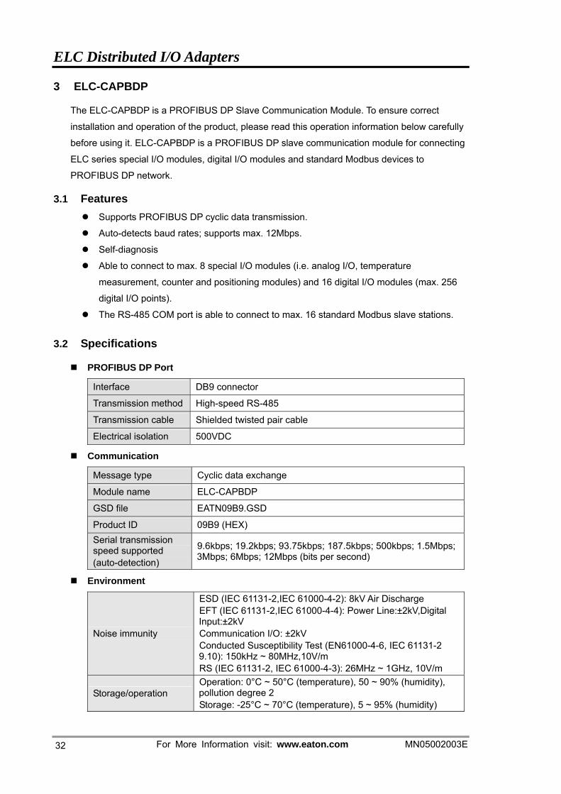
Environment
Noise immunity
ESD (IEC 61131-2,IEC 61000-4-2): 8kV Air Discharge EFT (IEC 61131-2,IEC 61000-4-4): Power Line:±2kV,Digital Input:±2kV Communication I/O: ±2kV Conducted Susceptibility Test (EN61000-4-6, IEC 61131-2 9.10): 150kHz ~ 80MHz,10V/m RS (IEC 61131-2, IEC 61000-4-3): 26MHz ~ 1GHz, 10V/m
Storage/operation Operation: 0°C ~ 50°C (temperature), 50 ~ 90% (humidity), pollution degree 2 Storage: -25°C ~ 70°C (temperature), 5 ~ 95% (humidity)
ELC Distributed I/O Adapters
MN05002003E For More Information visit: www.eaton.com 33
Shock/vibration immunity
International standards: IEC 61131-2,IEC 68-2-6 (TEST Fc)/IEC 61131-2& IEC 68-2-27 (TEST Ea)
Electrical specification
Power supply voltage 24VDC
Insulation voltage 500VDC
Power consumption 2.5W
Weight 90g
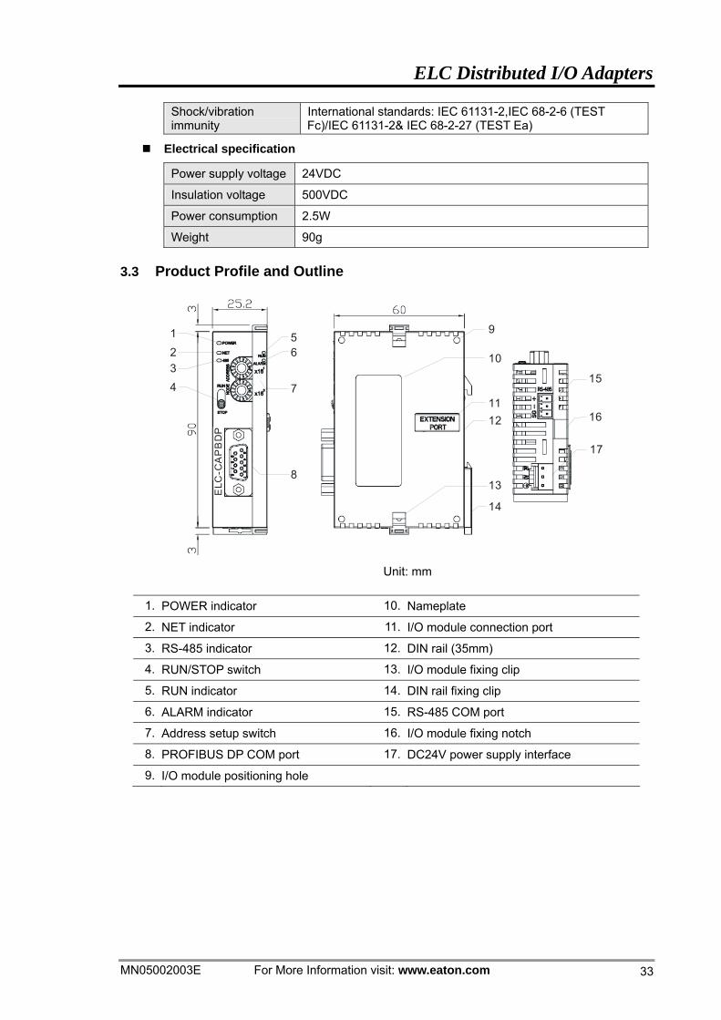
3.3 Product Profile and Outline
123
56
9
8
74
10
1112
13
14
15
16
17
ELC
-CA
PB
DP
Unit: mm
1. POWER indicator 10. Nameplate
2. NET indicator 11. I/O module connection port
3. RS-485 indicator 12. DIN rail (35mm)
4. RUN/STOP switch 13. I/O module fixing clip
5. RUN indicator 14. DIN rail fixing clip
6. ALARM indicator 15. RS-485 COM port
7. Address setup switch 16. I/O module fixing notch
8. PROFIBUS DP COM port 17. DC24V power supply interface
9. I/O module positioning hole
ELC Distributed I/O Adapters
For More Information visit: www.eaton.com MN05002003E
34
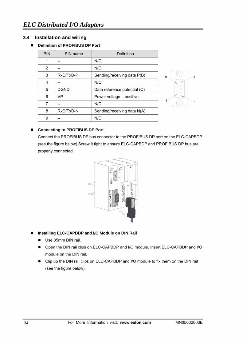
3.4 Installation and wiring Definition of PROFIBUS DP Port
PIN PIN name Definition
1 -- N/C
2 -- N/C
3 RxD/TxD-P Sending/receiving data P(B)
4 -- N/C
5 DGND Data reference potential (C)
6 VP Power voltage – positive
7 -- N/C
8 RxD/TxD-N Sending/receiving data N(A)
9 -- N/C
1
59
6
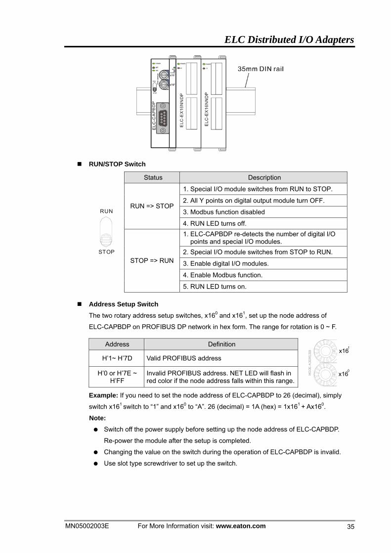
Connecting to PROFIBUS DP Port
Connect the PROFIBUS DP bus connector to the PROFIBUS DP port on the ELC-CAPBDP
(see the figure below) Screw it tight to ensure ELC-CAPBDP and PROFIBUS DP bus are
properly connected.
Installing ELC-CAPBDP and I/O Module on DIN Rail Use 35mm DIN rail.
Open the DIN rail clips on ELC-CAPBDP and I/O module. Insert ELC-CAPBDP and I/O
module on the DIN rail.
Clip up the DIN rail clips on ELC-CAPBDP and I/O module to fix them on the DIN rail
(see the figure below).
ELC Distributed I/O Adapters
MN05002003E For More Information visit: www.eaton.com 35
RUN/STOP Switch
Status Description
1. Special I/O module switches from RUN to STOP.
2. All Y points on digital output module turn OFF.
3. Modbus function disabled RUN => STOP
4. RUN LED turns off. 1. ELC-CAPBDP re-detects the number of digital I/O
points and special I/O modules. 2. Special I/O module switches from STOP to RUN.
3. Enable digital I/O modules.
4. Enable Modbus function.
STOP
RUN
STOP => RUN
5. RUN LED turns on.
Address Setup Switch The two rotary address setup switches, x160 and x161, set up the node address of
ELC-CAPBDP on PROFIBUS DP network in hex form. The range for rotation is 0 ~ F.
Address Definition
H’1~ H’7D Valid PROFIBUS address
H’0 or H’7E ~ H’FF
Invalid PROFIBUS address. NET LED will flash in red color if the node address falls within this range.
0
x16
1x16
Example: If you need to set the node address of ELC-CAPBDP to 26 (decimal), simply
switch x161 switch to “1” and x160 to “A”. 26 (decimal) = 1A (hex) = 1x161 + Ax160.
Note: Switch off the power supply before setting up the node address of ELC-CAPBDP.
Re-power the module after the setup is completed.
Changing the value on the switch during the operation of ELC-CAPBDP is invalid.
Use slot type screwdriver to set up the switch.
ELC Distributed I/O Adapters
For More Information visit: www.eaton.com MN05002003E
36
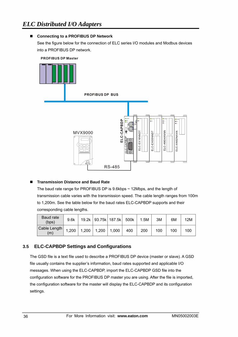
Connecting to a PROFIBUS DP Network
See the figure below for the connection of ELC series I/O modules and Modbus devices
into a PROFIBUS DP network.
Transmission Distance and Baud Rate
The baud rate range for PROFIBUS DP is 9.6kbps ~ 12Mbps, and the length of
transmission cable varies with the transmission speed. The cable length ranges from 100m
to 1,200m. See the table below for the baud rates ELC-CAPBDP supports and their
corresponding cable lengths.
Baud rate (bps) 9.6k 19.2k 93.75k 187.5k 500k 1.5M 3M 6M 12M
Cable Length (m) 1,200 1,200 1,200 1,000 400 200 100 100 100
3.5 ELC-CAPBDP Settings and Configurations
The GSD file is a text file used to describe a PROFIBUS DP device (master or slave). A GSD
file usually contains the supplier’s information, baud rates supported and applicable I/O
messages. When using the ELC-CAPBDP, import the ELC-CAPBDP GSD file into the
configuration software for the PROFIBUS DP master you are using. After the file is imported,
the configuration software for the master will display the ELC-CAPBDP and its configuration
settings.
ELC Distributed I/O Adapters
MN05002003E For More Information visit: www.eaton.com 37
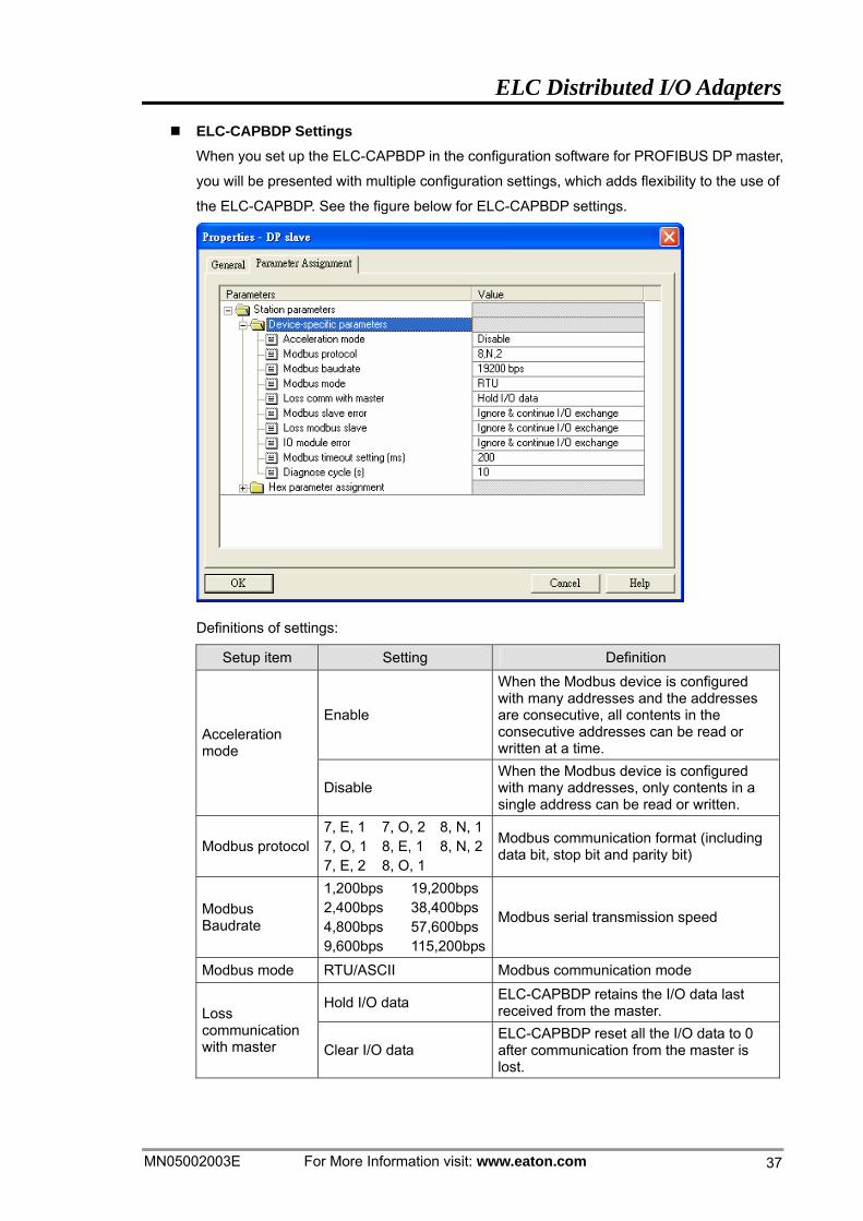
ELC-CAPBDP Settings When you set up the ELC-CAPBDP in the configuration software for PROFIBUS DP master,
you will be presented with multiple configuration settings, which adds flexibility to the use of
the ELC-CAPBDP. See the figure below for ELC-CAPBDP settings.
Definitions of settings:
Setup item Setting Definition
Enable
When the Modbus device is configured with many addresses and the addresses are consecutive, all contents in the consecutive addresses can be read or written at a time.
Acceleration mode
Disable When the Modbus device is configured with many addresses, only contents in a single address can be read or written.
Modbus protocol 7, E, 17, O, 17, E, 2
7, O, 28, E, 18, O, 1
8, N, 18, N, 2 Modbus communication format (including
data bit, stop bit and parity bit)
Modbus Baudrate
1,200bps 2,400bps 4,800bps 9,600bps
19,200bps 38,400bps 57,600bps 115,200bps
Modbus serial transmission speed
Modbus mode RTU/ASCII Modbus communication mode
Hold I/O data ELC-CAPBDP retains the I/O data last received from the master. Loss
communication with master Clear I/O data
ELC-CAPBDP reset all the I/O data to 0 after communication from the master is lost.
ELC Distributed I/O Adapters
For More Information visit: www.eaton.com MN05002003E
38
Setup item Setting Definition
Ignore & continue I/O exchange
ELC-CAPBDP continues exchanging data with the master even when Modbus read/write error occurs. Modbus slave
error Stop I/O exchange &report fault
ELC-CAPBDP stops exchanging data with the master when Modbus read/write error occurs.
Ignore & continue I/O exchange
ELC-CAPBDP continues exchanging data with the master even when the Modbus slave is disconnected.
Continue & report alarm ELC-CAPBDP continues exchanging data with the master and alarms it when there is Modbus slave getting disconnected.
Loss Modbus slave
Stop I/O exchange & report fault
ELC-CAPBDP stops exchanging data with the master and reports error to it when there is Modbus slave getting disconnected.
Ignore & continue I/O exchange
ELC-CAPBDP continues exchanging data with the master even when error occurs in the right-side special I/O module.
IO module error
Continue & report alarm ELC-CAPBDP continues exchanging data with the master and alarms it when error occurs in the right-side special I/O module.
IO module error Stop I/O exchange & report fault
ELC-CAPBDP stops exchanging data with the master and reports error to it when error occurs in the right-side special I/O module.
Modbus timeout setting (ms) 0 ~ 65535 Modbus communication timeout. Unit: ms
Diagnose cycle (s) 1 ~ 20 Cycle for ELC-CAPBDP to diagnose the
right-side special I/O module. Unit: s
Configuration Items ELC-CAPBDP offers flexible configuration when being configured in PROFIBUS DP master
configuration tool, for example, you can configure digital I/O modules or special I/O
modules by the actual name of the module, or self-define the configuration.
Configuration item Configurable device Configuration method Modbus 1 read address Modbus 2 read address Modbus 4 read address Modbus 8 read address Modbus 1 write address
Modbus devices connected to ELC-CAPBDP Modbus
Modbus 2 write address
Modbus devices connected to ELC-CAPBDP Modbus
ELC Distributed I/O Adapters
MN05002003E For More Information visit: www.eaton.com 39
Configuration item Configurable device Configuration method Modbus 4 write address Modbus 8 write address Modbus 1 read & write address Modbus 2 read & write address Modbus 4 read & write address Modbus 8 read & write address
Modbus devices connected to ELC-CAPBDP Modbus
ELC-EX08NNDN ELC-EX08NNDN connected to ELC-CAPBDP
ELC-EX08NNNT ELC-EX08NNNR or ELC-EX08NNNT connected to ELC-CAPBDP
ELC-EX08NNDR/T ELC-EX08NNDR or ELC-EX08NNDT connected to ELC-CAPBDP
ELC-EX16NNDR/T ELC-EX16NNDR or ELC-EX16NNDT connected to ELC-CAPBDP
ELC-EX08NNSN ELC-EX08NNSN module connected to ELC-CAPBDP
Standard configuration method for digital I/O module
8 DI
8 DO
8 DIDO
16 DI
16 DO
16 DIDO
32 DI
32 DO
32 DIDO
64 DI
64 DO
64 DIDO
Digital I/O modules connected to ELC-CAPBDP
Self-defined configuration method for digital I/O module
ELC-AN04ANNN ELC-AN04ANNN connected to ELC-CAPBDP
ELC-AN06ANNN ELC-AN06ANNN connected to ELC-CAPBDP
ELC-AN02NANN ELC-AN02NANN connected to ELC-CAPBDP
Standard configuration method for special I/O module
ELC-AN04NANN ELC-AN04NANN connected to ELC-CAPBDP
Standard configuration method for special I/O

ELC Distributed I/O Adapters
For More Information visit: www.eaton.com MN05002003E
40
Configuration item Configurable device Configuration method
ELC-AN06AANN ELC-AN06AANN connected to ELC-CAPBDP
ELC-PT04ANNN ELC-PT04ANNN connected to ELC-CAPBDP
ELC-TC04ANNN ELC-TC04ANNN connected to ELC-CAPBDP
module
1 AI
2 AI
4 AI
8 AI
1 AO
2 AO
4 AO
8 AO
1 AIAO
2 AIAO
4 AIAO
8 AIAO
Special I/O modules connected to ELC-CAPBDP
Self-defined configuration method for special I/O module
Settings of Configuration Items
Settings of Configuration Items for Digital I/O Modules
There are 2 types of configuration items for digital I/O modules, standard configuration
and self-defined configuration. By standard configuration, the digital I/O module is
named after its actual name, whereas it is named after the number of points by
self-defined configuration. You do not have to set up parameters in the configuration.
The digital I/O can correspond to the master directly after the configuration
Settings of Configuration Items for Special I/O Modules
The special I/O module is named after its actual name in the configuration. You can
configure special I/O module by standard configuration items. Detailed configuration
methods will be explained in the following paragraphs.
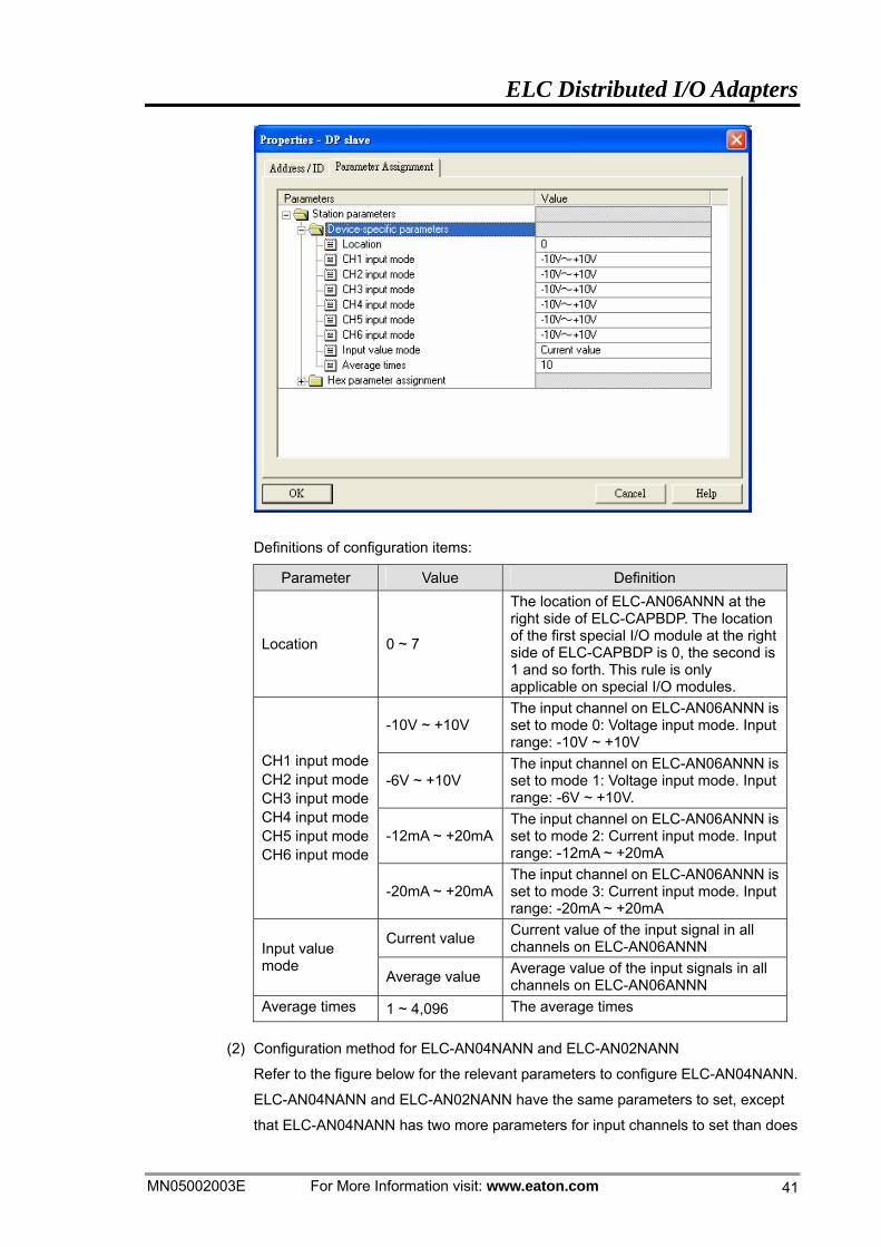
(1) Configuration method for ELC-AN06ANNN and ELC-AN04ANNN
Refer to the figure below for the relevant parameters to configure ELC-AN06ANNN.
ELC-AN04ANNN and ELC-AN06ANNN have the same parameters to set, except
that ELC-AN06ANNN has two more parameters for output channels to set than
does ELC-AN04ANNN (Therefore, only the parameter settings for ELC-AN06ANNN
are introduced in this section).
ELC Distributed I/O Adapters
MN05002003E For More Information visit: www.eaton.com 41
Definitions of configuration items:
Parameter Value Definition
Location 0 ~ 7
The location of ELC-AN06ANNN at the right side of ELC-CAPBDP. The location of the first special I/O module at the right side of ELC-CAPBDP is 0, the second is 1 and so forth. This rule is only applicable on special I/O modules.
-10V ~ +10V The input channel on ELC-AN06ANNN is set to mode 0: Voltage input mode. Input range: -10V ~ +10V
-6V ~ +10V The input channel on ELC-AN06ANNN is set to mode 1: Voltage input mode. Input range: -6V ~ +10V.
-12mA ~ +20mAThe input channel on ELC-AN06ANNN is set to mode 2: Current input mode. Input range: -12mA ~ +20mA
CH1 input modeCH2 input modeCH3 input modeCH4 input modeCH5 input modeCH6 input mode
-20mA ~ +20mAThe input channel on ELC-AN06ANNN is set to mode 3: Current input mode. Input range: -20mA ~ +20mA
Current value Current value of the input signal in all channels on ELC-AN06ANNN Input value
mode Average value Average value of the input signals in all
channels on ELC-AN06ANNN Average times 1 ~ 4,096 The average times
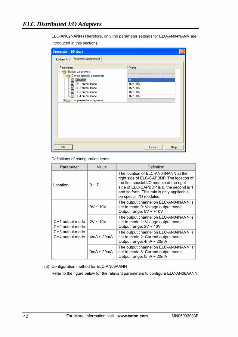
(2) Configuration method for ELC-AN04NANN and ELC-AN02NANN
Refer to the figure below for the relevant parameters to configure ELC-AN04NANN.
ELC-AN04NANN and ELC-AN02NANN have the same parameters to set, except
that ELC-AN04NANN has two more parameters for input channels to set than does
ELC Distributed I/O Adapters
For More Information visit: www.eaton.com MN05002003E
42
ELC-AN02NANN (Therefore, only the parameter settings for ELC-AN04NANN are
introduced in this section).
Definitions of configuration items:
Parameter Value Definition
Location 0 ~ 7
The location of ELC-AN04NANN at the right side of ELC-CAPBDP. The location of the first special I/O module at the right side of ELC-CAPBDP is 0, the second is 1 and so forth. This rule is only applicable on special I/O modules.
0V ~ 10V The output channel on ELC-AN04NANN is set to mode 0: Voltage output mode. Output range: 0V ~ +10V
2V ~ 10V The output channel on ELC-AN04NANN is set to mode 1: Voltage output mode. Output range: 2V ~ 10V
4mA ~ 20mAThe output channel on ELC-AN04NANN is set to mode 2: Current output mode. Output range: 4mA ~ 20mA
CH1 output mode CH2 output mode CH3 output mode CH4 output mode
0mA ~ 20mAThe output channel on ELC-AN04NANN is set to mode 3: Current output mode. Output range: 0mA ~ 20mA
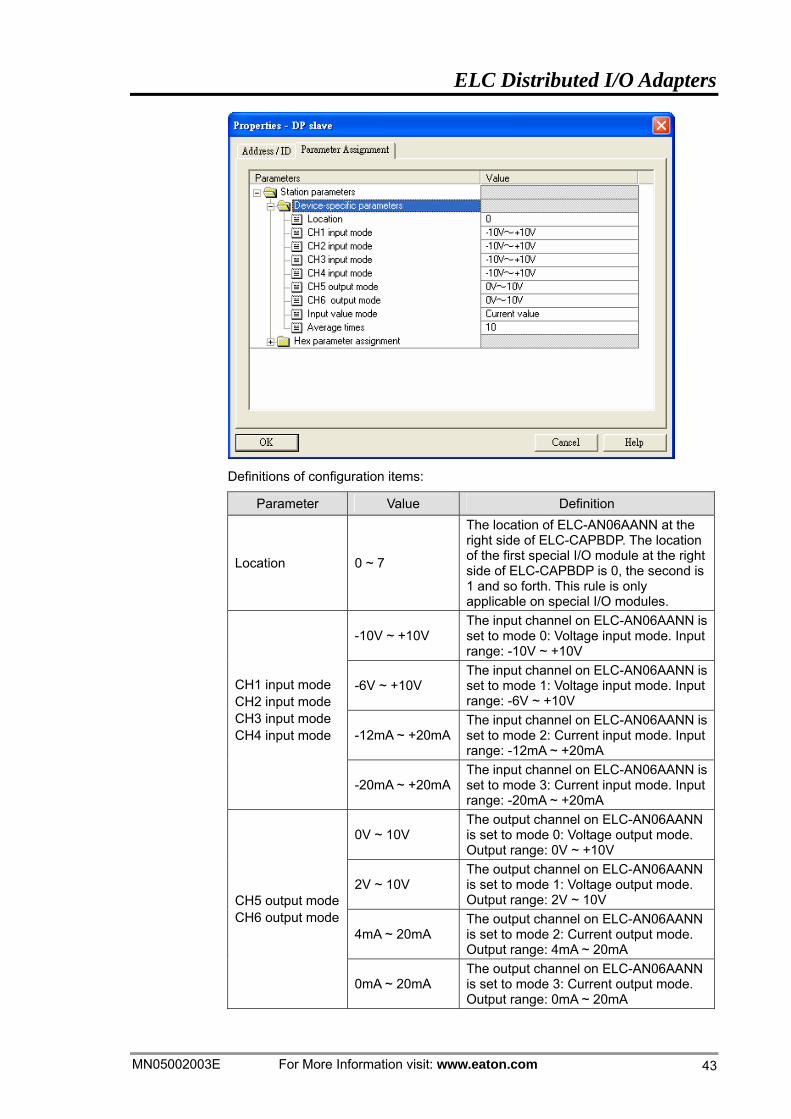
(3) Configuration method for ELC-AN06AANN
Refer to the figure below for the relevant parameters to configure ELC-AN06AANN.
ELC Distributed I/O Adapters
MN05002003E For More Information visit: www.eaton.com 43
Definitions of configuration items:
Parameter Value Definition
Location 0 ~ 7
The location of ELC-AN06AANN at the right side of ELC-CAPBDP. The location of the first special I/O module at the right side of ELC-CAPBDP is 0, the second is 1 and so forth. This rule is only applicable on special I/O modules.
-10V ~ +10V The input channel on ELC-AN06AANN is set to mode 0: Voltage input mode. Input range: -10V ~ +10V
-6V ~ +10V The input channel on ELC-AN06AANN is set to mode 1: Voltage input mode. Input range: -6V ~ +10V
-12mA ~ +20mAThe input channel on ELC-AN06AANN is set to mode 2: Current input mode. Input range: -12mA ~ +20mA
CH1 input mode CH2 input mode CH3 input mode CH4 input mode
-20mA ~ +20mAThe input channel on ELC-AN06AANN is set to mode 3: Current input mode. Input range: -20mA ~ +20mA
0V ~ 10V The output channel on ELC-AN06AANN is set to mode 0: Voltage output mode. Output range: 0V ~ +10V
2V ~ 10V The output channel on ELC-AN06AANN is set to mode 1: Voltage output mode. Output range: 2V ~ 10V
4mA ~ 20mA The output channel on ELC-AN06AANN is set to mode 2: Current output mode. Output range: 4mA ~ 20mA
CH5 output modeCH6 output mode
0mA ~ 20mA The output channel on ELC-AN06AANN is set to mode 3: Current output mode. Output range: 0mA ~ 20mA
ELC Distributed I/O Adapters
For More Information visit: www.eaton.com MN05002003E
44
Parameter Value Definition
Current value Current value of the input signal in CH1 ~ CH4 on ELC-AN06AANN
Input value mode Average value Average value of the input signals in
CH1 ~ CH4 on ELC-AN06AANN Set average times 1 ~ 4,096 The average times
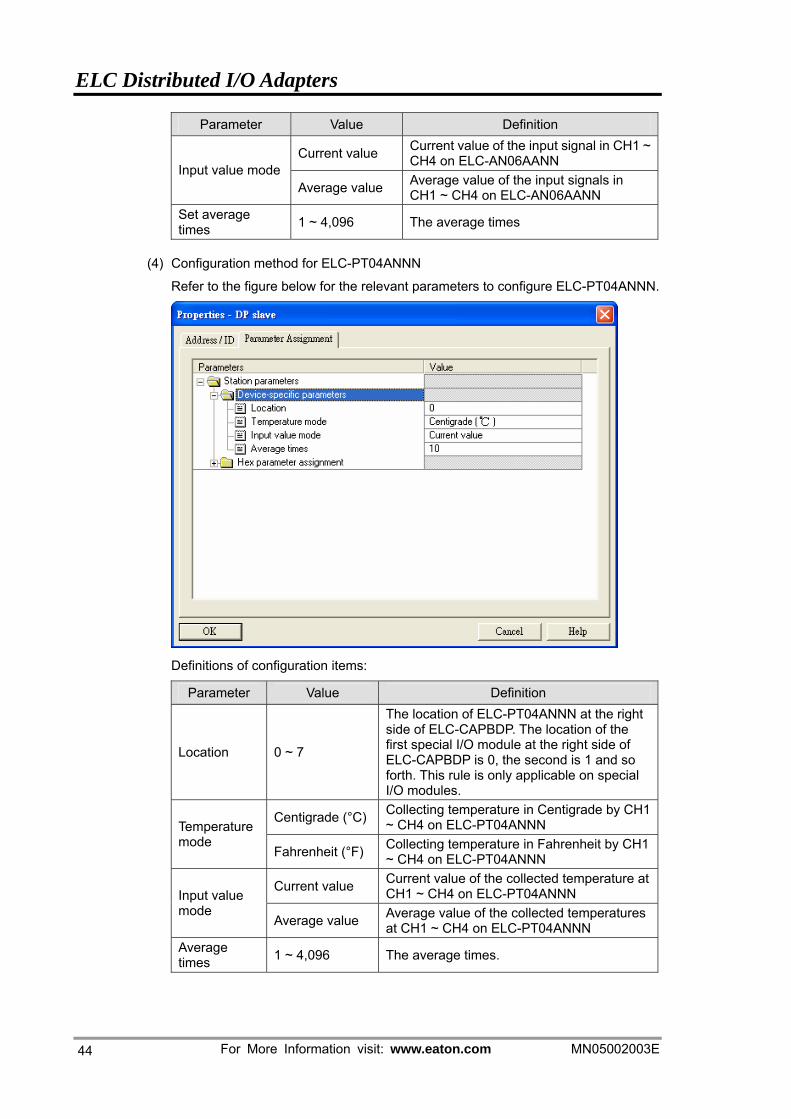
(4) Configuration method for ELC-PT04ANNN
Refer to the figure below for the relevant parameters to configure ELC-PT04ANNN.
Definitions of configuration items:
Parameter Value Definition
Location 0 ~ 7
The location of ELC-PT04ANNN at the right side of ELC-CAPBDP. The location of the first special I/O module at the right side of ELC-CAPBDP is 0, the second is 1 and so forth. This rule is only applicable on special I/O modules.
Centigrade (°C) Collecting temperature in Centigrade by CH1 ~ CH4 on ELC-PT04ANNN Temperature
mode Fahrenheit (°F) Collecting temperature in Fahrenheit by CH1
~ CH4 on ELC-PT04ANNN
Current value Current value of the collected temperature at CH1 ~ CH4 on ELC-PT04ANNN Input value
mode Average value Average value of the collected temperatures
at CH1 ~ CH4 on ELC-PT04ANNN Average times 1 ~ 4,096 The average times.
ELC Distributed I/O Adapters
MN05002003E For More Information visit: www.eaton.com 45
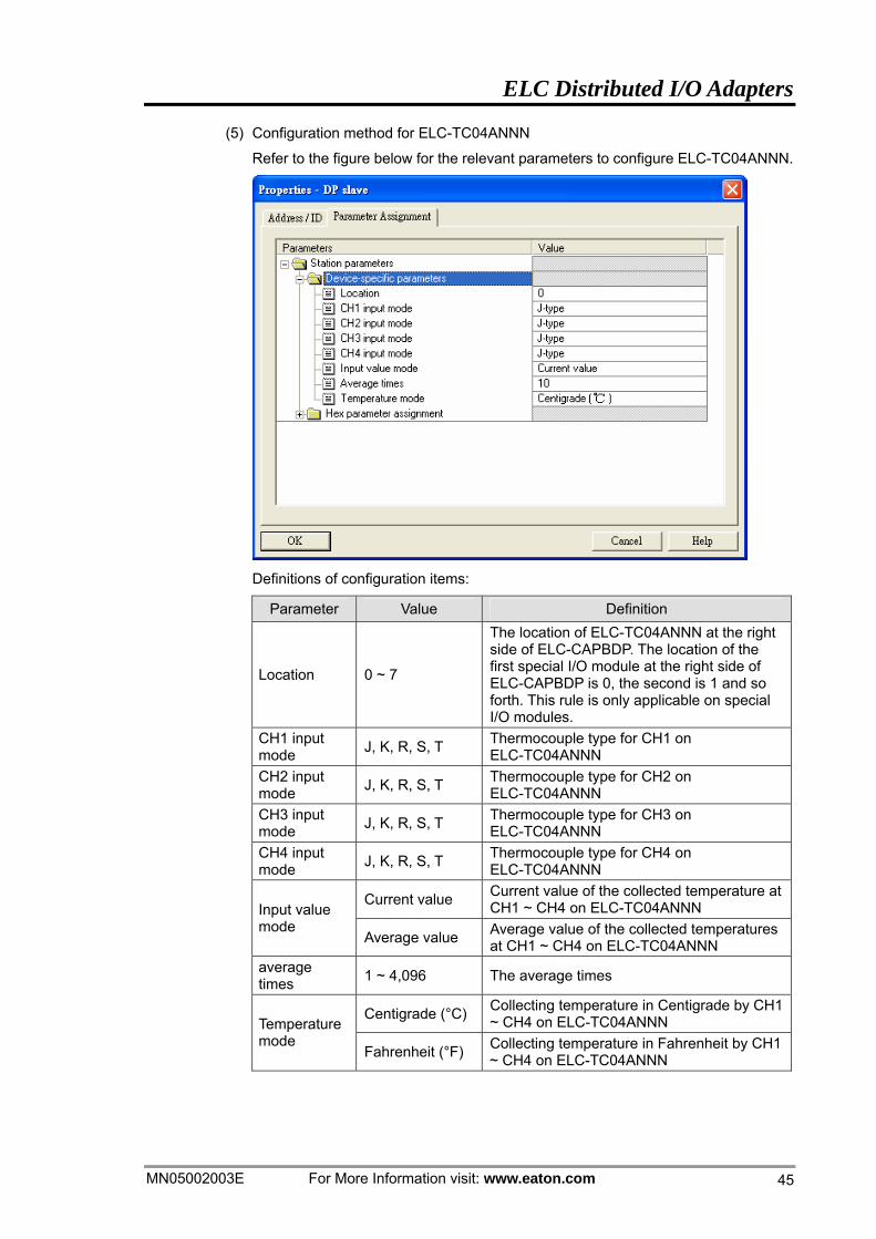
(5) Configuration method for ELC-TC04ANNN
Refer to the figure below for the relevant parameters to configure ELC-TC04ANNN.
Definitions of configuration items:
Parameter Value Definition
Location 0 ~ 7
The location of ELC-TC04ANNN at the right side of ELC-CAPBDP. The location of the first special I/O module at the right side of ELC-CAPBDP is 0, the second is 1 and so forth. This rule is only applicable on special I/O modules.
CH1 input mode J, K, R, S, T Thermocouple type for CH1 on
ELC-TC04ANNN CH2 input mode J, K, R, S, T Thermocouple type for CH2 on
ELC-TC04ANNN CH3 input mode J, K, R, S, T Thermocouple type for CH3 on
ELC-TC04ANNN CH4 input mode J, K, R, S, T Thermocouple type for CH4 on
ELC-TC04ANNN
Current value Current value of the collected temperature at CH1 ~ CH4 on ELC-TC04ANNN Input value
mode Average value Average value of the collected temperatures
at CH1 ~ CH4 on ELC-TC04ANNN average times 1 ~ 4,096 The average times
Centigrade (°C) Collecting temperature in Centigrade by CH1 ~ CH4 on ELC-TC04ANNN Temperature
mode Fahrenheit (°F) Collecting temperature in Fahrenheit by CH1
~ CH4 on ELC-TC04ANNN
ELC Distributed I/O Adapters
For More Information visit: www.eaton.com MN05002003E
46
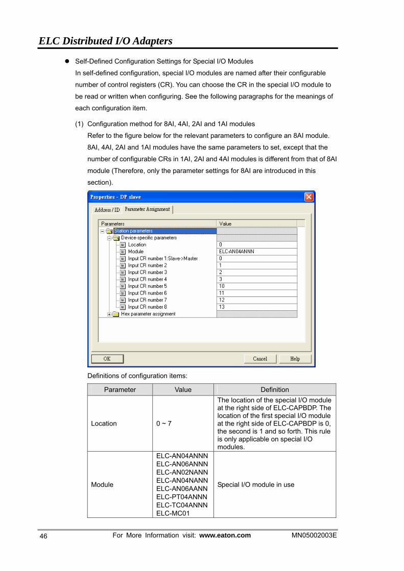
Self-Defined Configuration Settings for Special I/O Modules
In self-defined configuration, special I/O modules are named after their configurable
number of control registers (CR). You can choose the CR in the special I/O module to
be read or written when configuring. See the following paragraphs for the meanings of
each configuration item.
(1) Configuration method for 8AI, 4AI, 2AI and 1AI modules
Refer to the figure below for the relevant parameters to configure an 8AI module.
8AI, 4AI, 2AI and 1AI modules have the same parameters to set, except that the
number of configurable CRs in 1AI, 2AI and 4AI modules is different from that of 8AI
module (Therefore, only the parameter settings for 8AI are introduced in this
section).
Definitions of configuration items:
Parameter Value Definition
Location 0 ~ 7
The location of the special I/O module at the right side of ELC-CAPBDP. The location of the first special I/O module at the right side of ELC-CAPBDP is 0, the second is 1 and so forth. This rule is only applicable on special I/O modules.
Module
ELC-AN04ANNNELC-AN06ANNNELC-AN02NANNELC-AN04NANNELC-AN06AANNELC-PT04ANNN ELC-TC04ANNNELC-MC01
Special I/O module in use
ELC Distributed I/O Adapters
MN05002003E For More Information visit: www.eaton.com 47
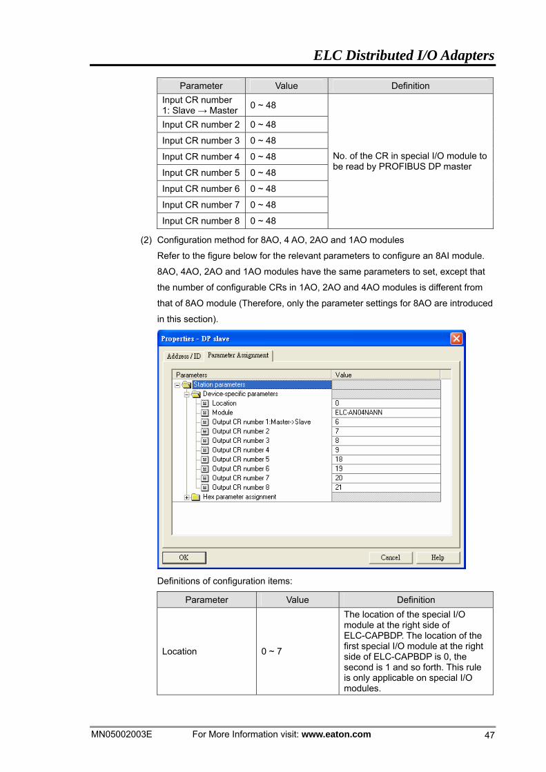
Parameter Value Definition Input CR number 1: Slave → Master 0 ~ 48
Input CR number 2 0 ~ 48
Input CR number 3 0 ~ 48
Input CR number 4 0 ~ 48
Input CR number 5 0 ~ 48
Input CR number 6 0 ~ 48
Input CR number 7 0 ~ 48
Input CR number 8 0 ~ 48
No. of the CR in special I/O module to be read by PROFIBUS DP master
(2) Configuration method for 8AO, 4 AO, 2AO and 1AO modules
Refer to the figure below for the relevant parameters to configure an 8AI module.
8AO, 4AO, 2AO and 1AO modules have the same parameters to set, except that
the number of configurable CRs in 1AO, 2AO and 4AO modules is different from
that of 8AO module (Therefore, only the parameter settings for 8AO are introduced
in this section).
Definitions of configuration items:
Parameter Value Definition
Location 0 ~ 7
The location of the special I/O module at the right side of ELC-CAPBDP. The location of the first special I/O module at the right side of ELC-CAPBDP is 0, the second is 1 and so forth. This rule is only applicable on special I/O modules.
ELC Distributed I/O Adapters
For More Information visit: www.eaton.com MN05002003E
48
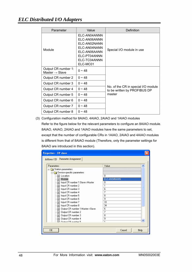
Parameter Value Definition
Module
ELC-AN04ANNNELC-AN06ANNNELC-AN02NANNELC-AN04NANNELC-AN06AANNELC-PT04ANNN ELC-TC04ANNNELC-MC01
Special I/O module in use
Output CR number 1: Master → Slave 0 ~ 48
Output CR number 2 0 ~ 48
Output CR number 3 0 ~ 48
Output CR number 4 0 ~ 48
Output CR number 5 0 ~ 48
Output CR number 6 0 ~ 48
Output CR number 7 0 ~ 48
Output CR number 8 0 ~ 48
No. of the CR in special I/O module to be written by PROFIBUS DP master
(3) Configuration method for 8AIAO, 4AIAO, 2AIAO and 1AIAO modules
Refer to the figure below for the relevant parameters to configure an 8AIAO module.
8AIAO, 4AIAO, 2AIAO and 1AIAO modules have the same parameters to set,
except that the number of configurable CRs in 1AIAO, 2AIAO and 4AIAO modules
is different from that of 8AIAO module (Therefore, only the parameter settings for
8AIAO are introduced in this section).
ELC Distributed I/O Adapters
MN05002003E For More Information visit: www.eaton.com 49
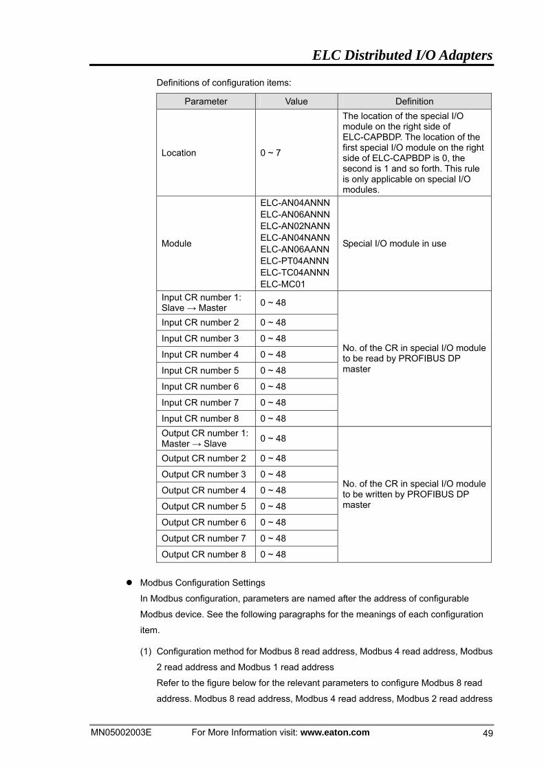
Definitions of configuration items:
Parameter Value Definition
Location 0 ~ 7
The location of the special I/O module on the right side of ELC-CAPBDP. The location of the first special I/O module on the right side of ELC-CAPBDP is 0, the second is 1 and so forth. This rule is only applicable on special I/O modules.
Module
ELC-AN04ANNNELC-AN06ANNNELC-AN02NANNELC-AN04NANNELC-AN06AANNELC-PT04ANNN ELC-TC04ANNNELC-MC01
Special I/O module in use
Input CR number 1: Slave → Master 0 ~ 48
Input CR number 2 0 ~ 48
Input CR number 3 0 ~ 48
Input CR number 4 0 ~ 48
Input CR number 5 0 ~ 48
Input CR number 6 0 ~ 48
Input CR number 7 0 ~ 48
Input CR number 8 0 ~ 48
No. of the CR in special I/O module to be read by PROFIBUS DP master
Output CR number 1: Master → Slave 0 ~ 48
Output CR number 2 0 ~ 48
Output CR number 3 0 ~ 48
Output CR number 4 0 ~ 48
Output CR number 5 0 ~ 48
Output CR number 6 0 ~ 48
Output CR number 7 0 ~ 48
Output CR number 8 0 ~ 48
No. of the CR in special I/O module to be written by PROFIBUS DP master
Modbus Configuration Settings
In Modbus configuration, parameters are named after the address of configurable
Modbus device. See the following paragraphs for the meanings of each configuration
item.
(1) Configuration method for Modbus 8 read address, Modbus 4 read address, Modbus
2 read address and Modbus 1 read address
Refer to the figure below for the relevant parameters to configure Modbus 8 read
address. Modbus 8 read address, Modbus 4 read address, Modbus 2 read address
ELC Distributed I/O Adapters
For More Information visit: www.eaton.com MN05002003E
50
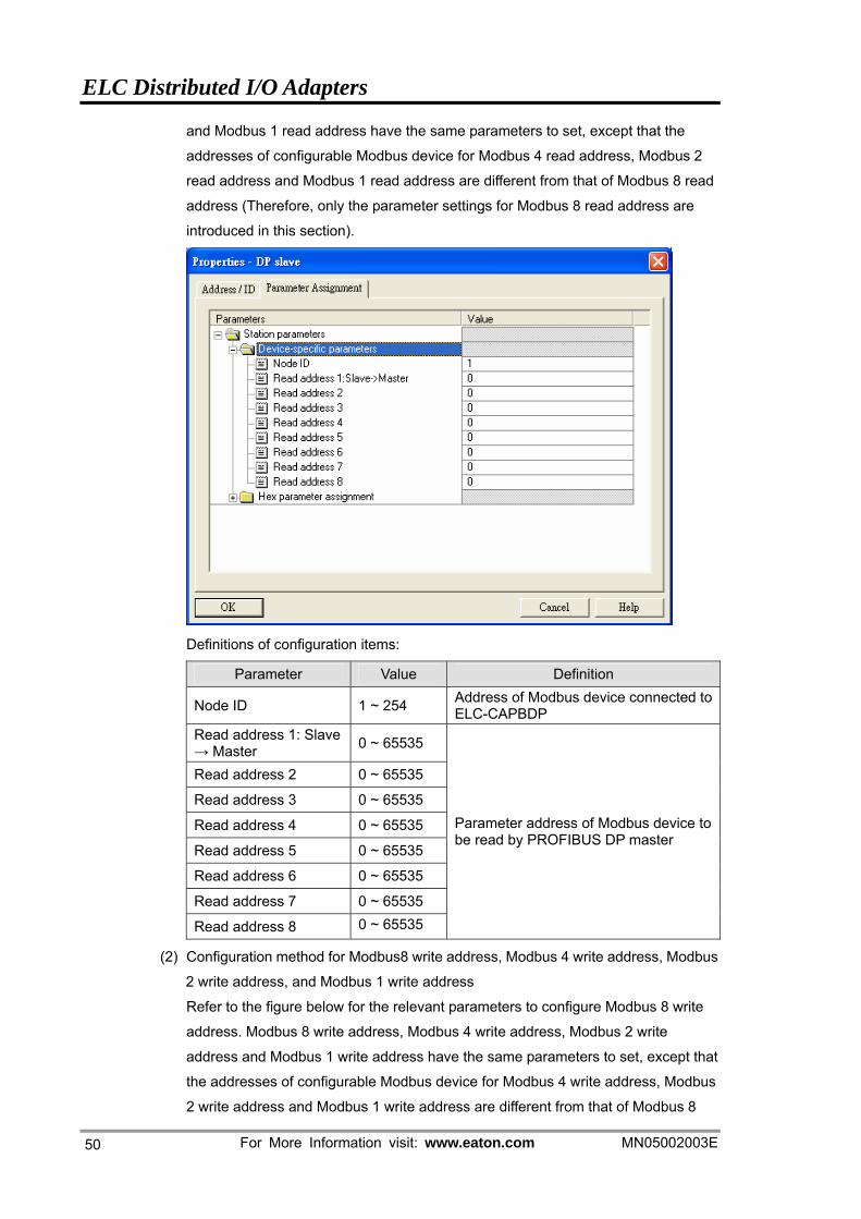
and Modbus 1 read address have the same parameters to set, except that the
addresses of configurable Modbus device for Modbus 4 read address, Modbus 2
read address and Modbus 1 read address are different from that of Modbus 8 read
address (Therefore, only the parameter settings for Modbus 8 read address are
introduced in this section).
Definitions of configuration items:
Parameter Value Definition
Node ID 1 ~ 254 Address of Modbus device connected to ELC-CAPBDP
Read address 1: Slave → Master 0 ~ 65535
Read address 2 0 ~ 65535
Read address 3 0 ~ 65535
Read address 4 0 ~ 65535
Read address 5 0 ~ 65535
Read address 6 0 ~ 65535
Read address 7 0 ~ 65535
Read address 8 0 ~ 65535
Parameter address of Modbus device to be read by PROFIBUS DP master
(2) Configuration method for Modbus8 write address, Modbus 4 write address, Modbus
2 write address, and Modbus 1 write address
Refer to the figure below for the relevant parameters to configure Modbus 8 write
address. Modbus 8 write address, Modbus 4 write address, Modbus 2 write
address and Modbus 1 write address have the same parameters to set, except that
the addresses of configurable Modbus device for Modbus 4 write address, Modbus
2 write address and Modbus 1 write address are different from that of Modbus 8
ELC Distributed I/O Adapters
MN05002003E For More Information visit: www.eaton.com 51
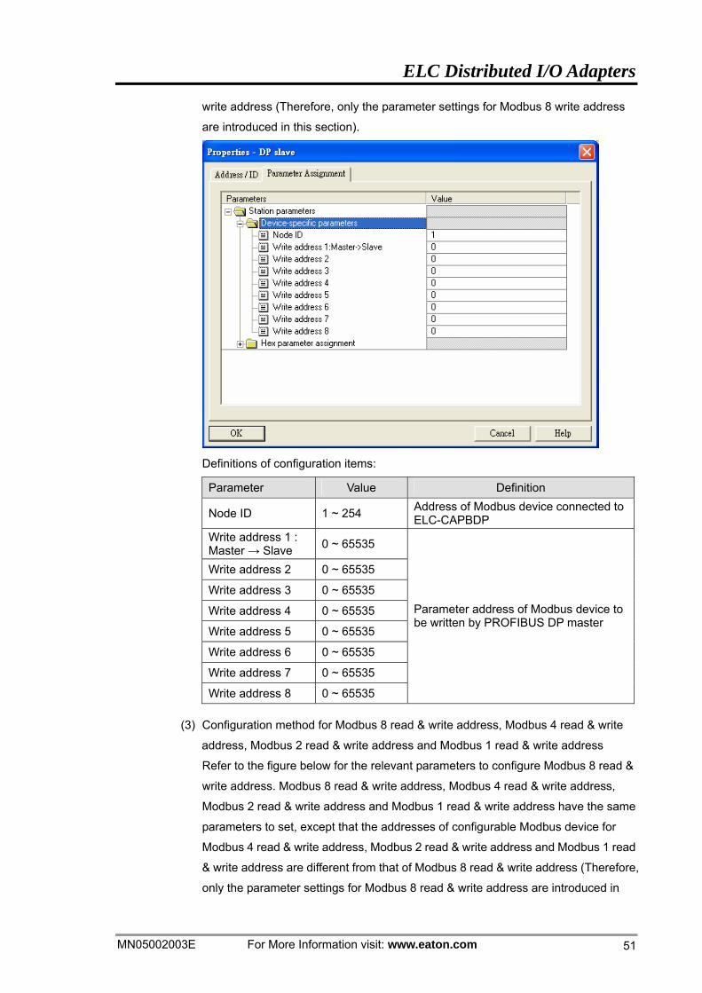
write address (Therefore, only the parameter settings for Modbus 8 write address
are introduced in this section).
Definitions of configuration items:
Parameter Value Definition
Node ID 1 ~ 254 Address of Modbus device connected to ELC-CAPBDP
Write address 1 : Master → Slave 0 ~ 65535
Write address 2 0 ~ 65535
Write address 3 0 ~ 65535
Write address 4 0 ~ 65535
Write address 5 0 ~ 65535
Write address 6 0 ~ 65535
Write address 7 0 ~ 65535
Write address 8 0 ~ 65535
Parameter address of Modbus device to be written by PROFIBUS DP master
(3) Configuration method for Modbus 8 read & write address, Modbus 4 read & write
address, Modbus 2 read & write address and Modbus 1 read & write address
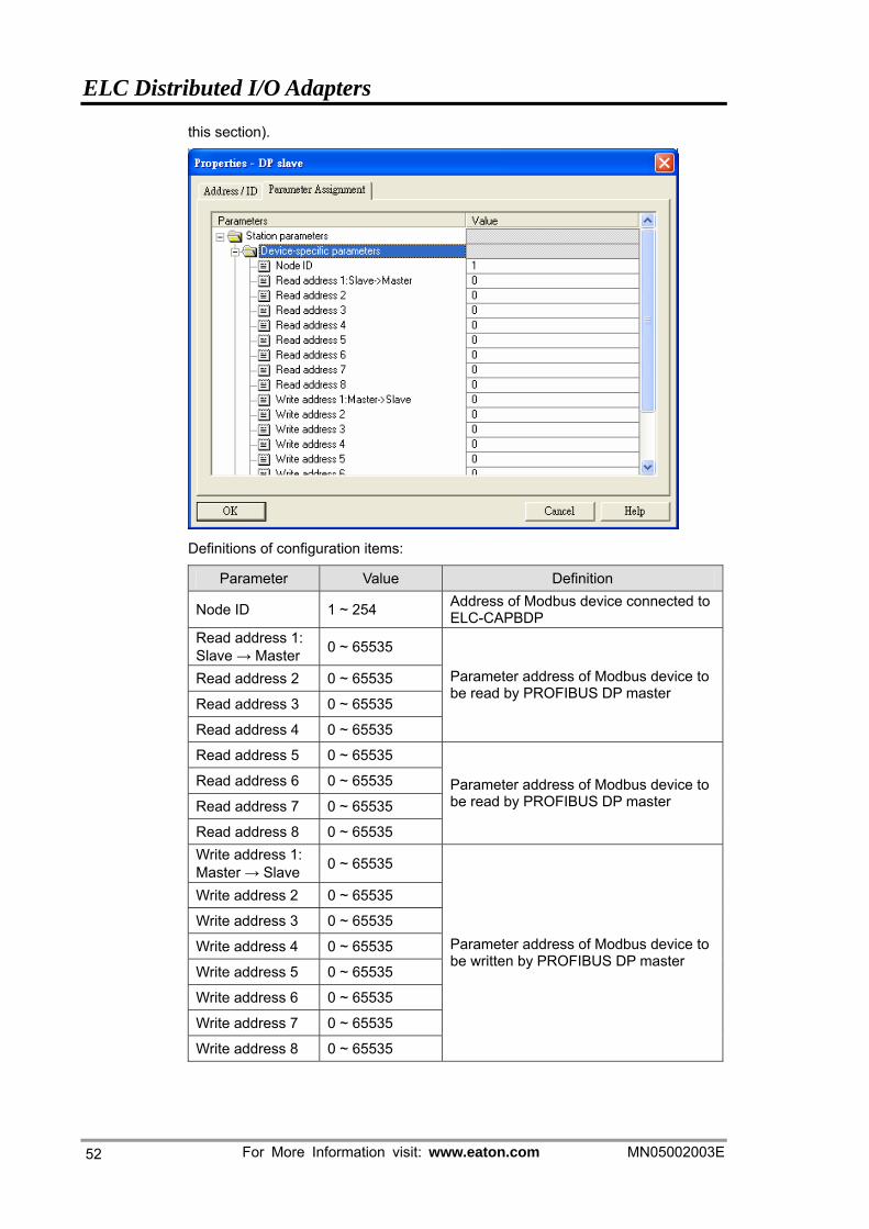
Refer to the figure below for the relevant parameters to configure Modbus 8 read &
write address. Modbus 8 read & write address, Modbus 4 read & write address,
Modbus 2 read & write address and Modbus 1 read & write address have the same
parameters to set, except that the addresses of configurable Modbus device for
Modbus 4 read & write address, Modbus 2 read & write address and Modbus 1 read
& write address are different from that of Modbus 8 read & write address (Therefore,
only the parameter settings for Modbus 8 read & write address are introduced in
ELC Distributed I/O Adapters
For More Information visit: www.eaton.com MN05002003E
52
this section).
Definitions of configuration items:
Parameter Value Definition
Node ID 1 ~ 254 Address of Modbus device connected to ELC-CAPBDP
Read address 1: Slave → Master 0 ~ 65535
Read address 2 0 ~ 65535
Read address 3 0 ~ 65535
Read address 4 0 ~ 65535
Parameter address of Modbus device to be read by PROFIBUS DP master
Read address 5 0 ~ 65535
Read address 6 0 ~ 65535
Read address 7 0 ~ 65535
Read address 8 0 ~ 65535
Parameter address of Modbus device to be read by PROFIBUS DP master
Write address 1: Master → Slave 0 ~ 65535
Write address 2 0 ~ 65535
Write address 3 0 ~ 65535
Write address 4 0 ~ 65535
Write address 5 0 ~ 65535
Write address 6 0 ~ 65535
Write address 7 0 ~ 65535
Write address 8 0 ~ 65535
Parameter address of Modbus device to be written by PROFIBUS DP master
ELC Distributed I/O Adapters
MN05002003E For More Information visit: www.eaton.com 53
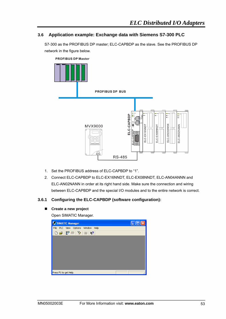
3.6 Application example: Exchange data with Siemens S7-300 PLC
S7-300 as the PROFIBUS DP master; ELC-CAPBDP as the slave. See the PROFIBUS DP
network in the figure below.
1. Set the PROFIBUS address of ELC-CAPBDP to “1”.
2. Connect ELC-CAPBDP to ELC-EX16NNDT, ELC-EX08NNDT, ELC-AN04ANNN and
ELC-AN02NANN in order at its right hand side. Make sure the connection and wiring
between ELC-CAPBDP and the special I/O modules and to the entire network is correct.
3.6.1 Configuring the ELC-CAPBDP (software configuration):
Create a new project Open SIMATIC Manager.
ELC Distributed I/O Adapters
For More Information visit: www.eaton.com MN05002003E
54
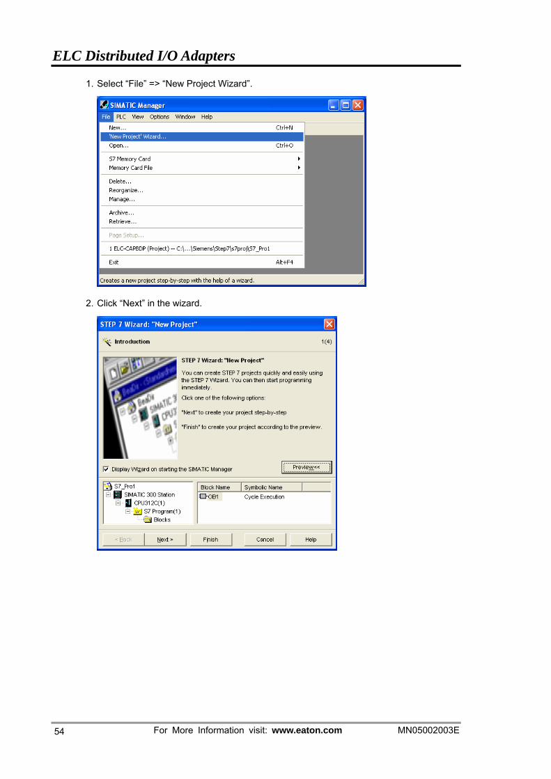
1. Select “File” => “New Project Wizard”.
2. Click “Next” in the wizard.
ELC Distributed I/O Adapters
MN05002003E For More Information visit: www.eaton.com 55
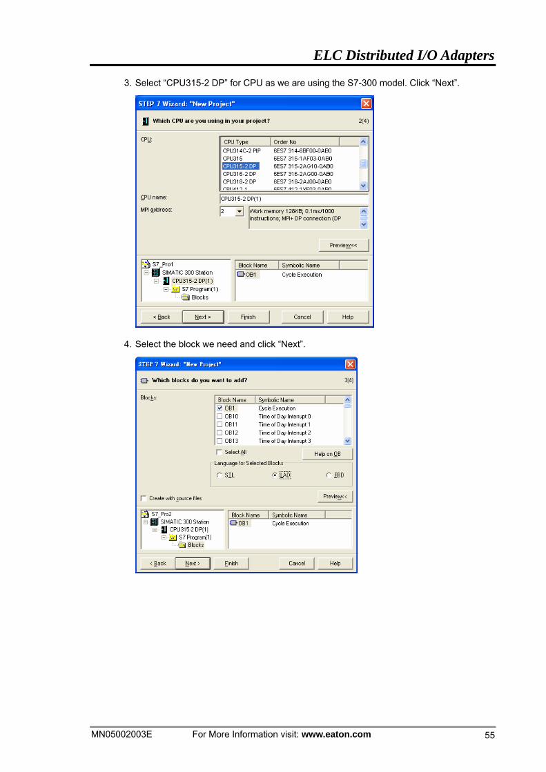
3. Select “CPU315-2 DP” for CPU as we are using the S7-300 model. Click “Next”.
4. Select the block we need and click “Next”.
ELC Distributed I/O Adapters
For More Information visit: www.eaton.com MN05002003E
56
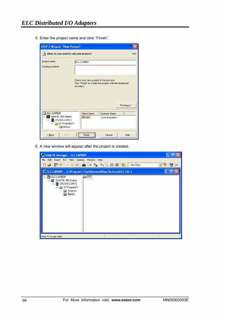
5. Enter the project name and click “Finish”.
6. A new window will appear after the project is created.
ELC Distributed I/O Adapters
MN05002003E For More Information visit: www.eaton.com 57
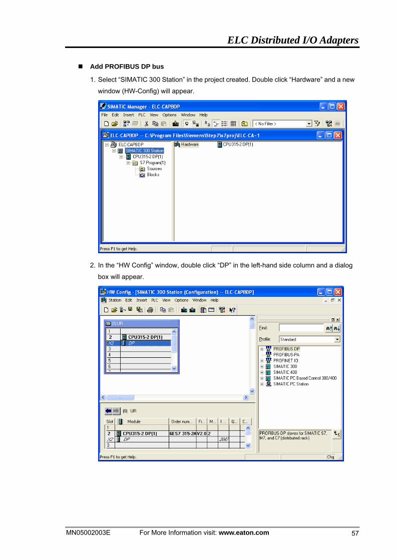
Add PROFIBUS DP bus
1. Select “SIMATIC 300 Station” in the project created. Double click “Hardware” and a new
window (HW-Config) will appear.
2. In the “HW Config” window, double click “DP” in the left-hand side column and a dialog
box will appear.
ELC Distributed I/O Adapters
For More Information visit: www.eaton.com MN05002003E
58
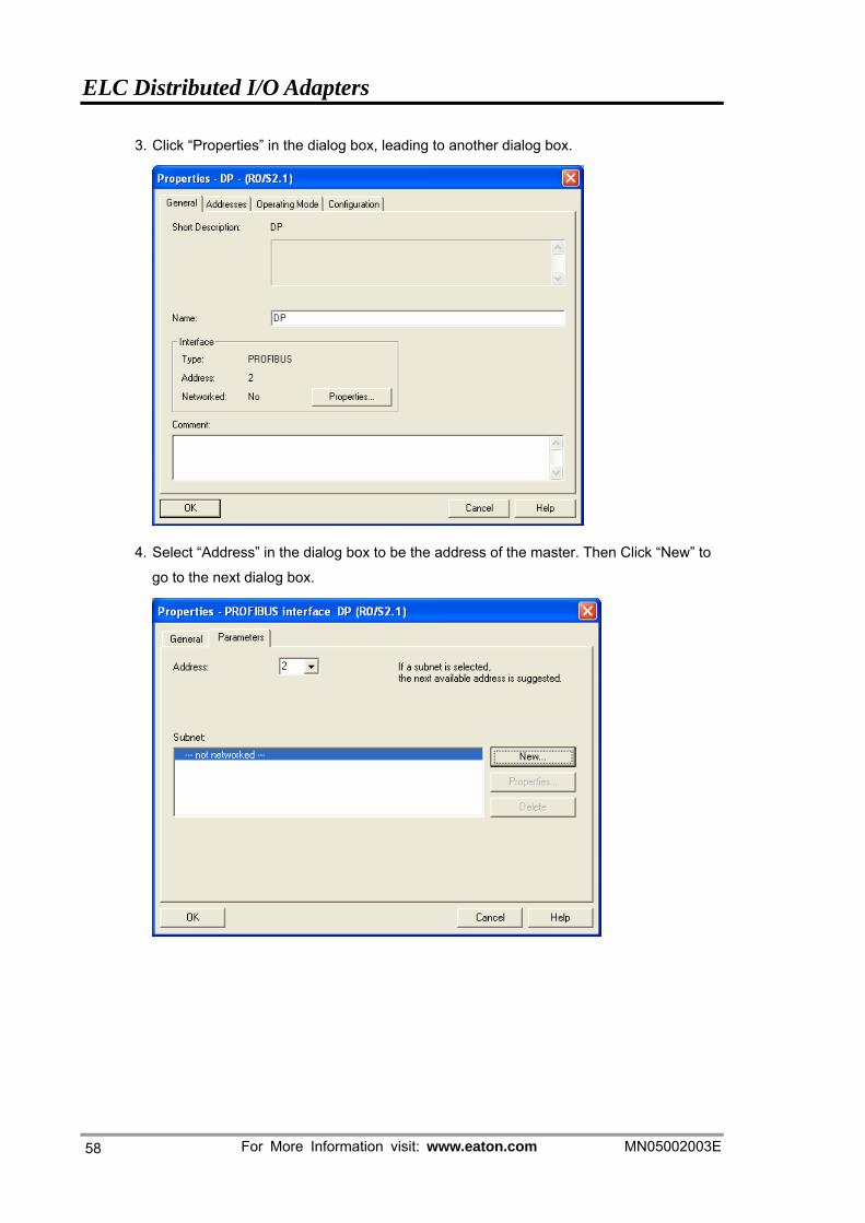
3. Click “Properties” in the dialog box, leading to another dialog box.
4. Select “Address” in the dialog box to be the address of the master. Then Click “New” to
go to the next dialog box.
ELC Distributed I/O Adapters
MN05002003E For More Information visit: www.eaton.com 59
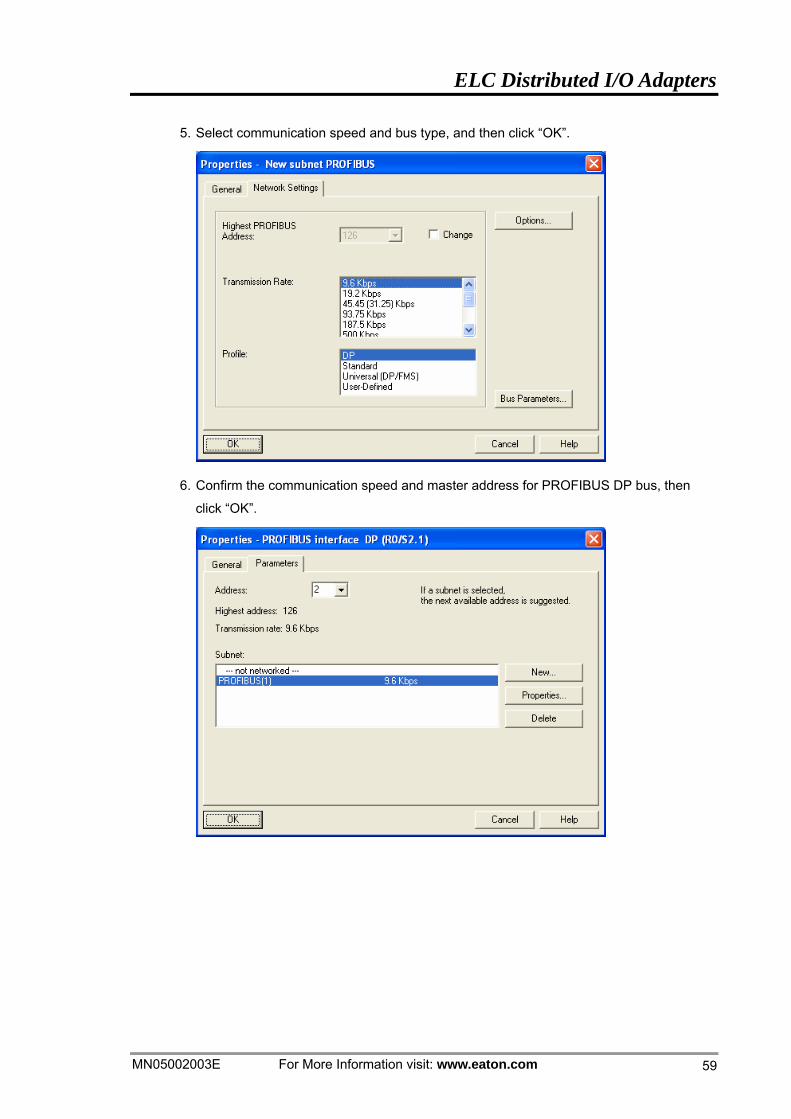
5. Select communication speed and bus type, and then click “OK”.
6. Confirm the communication speed and master address for PROFIBUS DP bus, then
click “OK”.
ELC Distributed I/O Adapters
For More Information visit: www.eaton.com MN05002003E
60
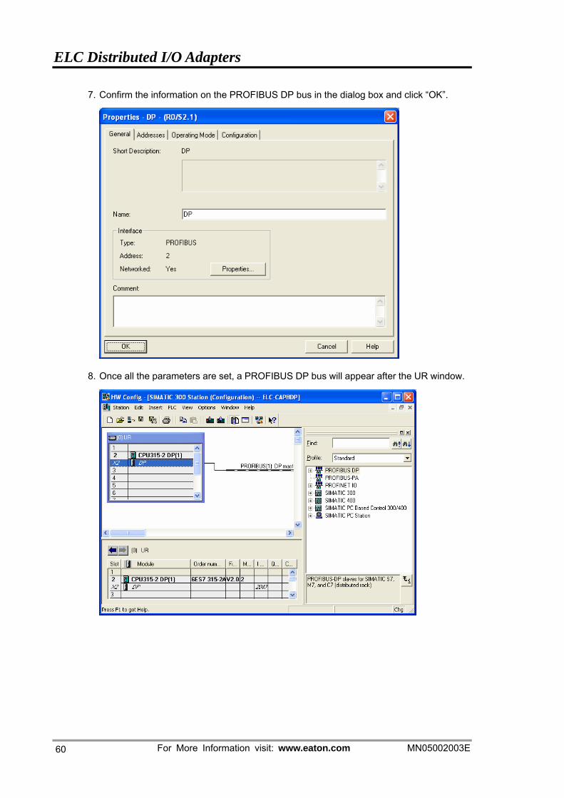
7. Confirm the information on the PROFIBUS DP bus in the dialog box and click “OK”.
8. Once all the parameters are set, a PROFIBUS DP bus will appear after the UR window.
ELC Distributed I/O Adapters
MN05002003E For More Information visit: www.eaton.com 61
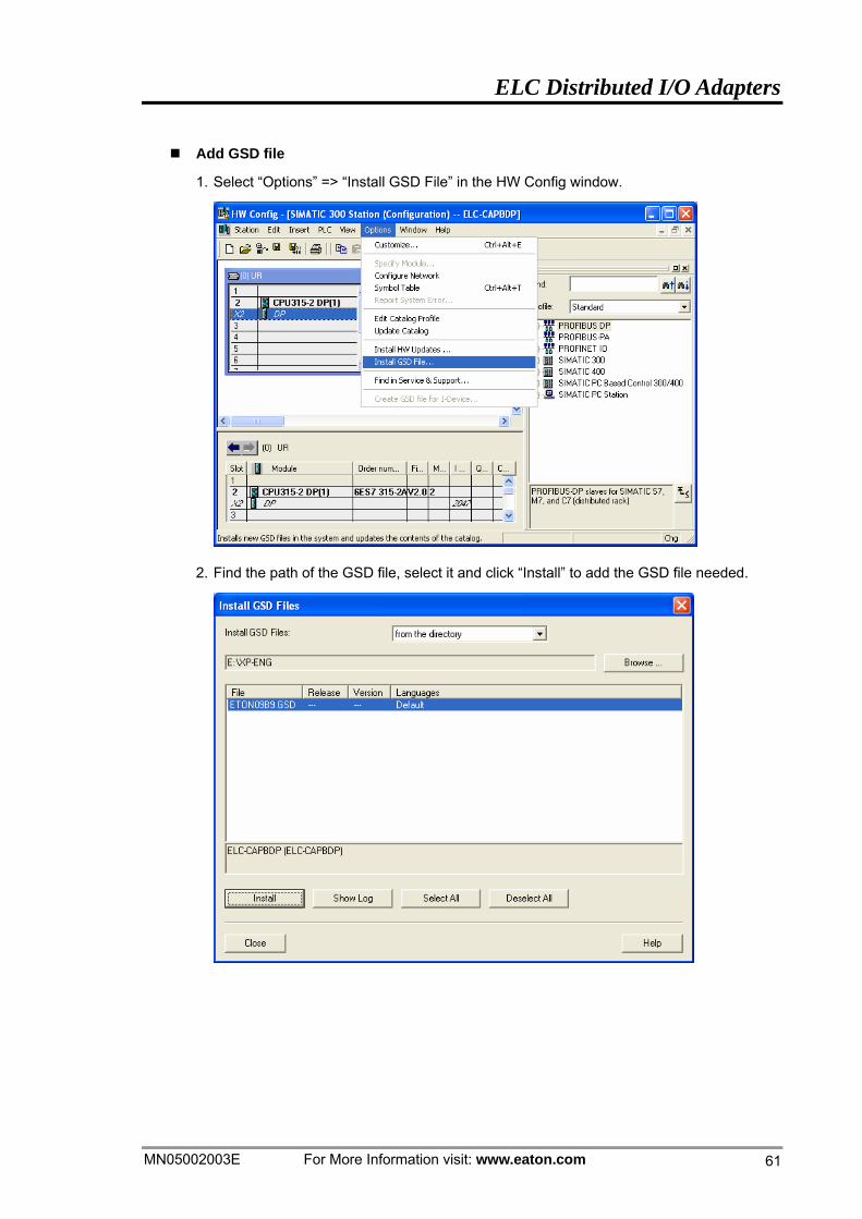
Add GSD file
1. Select “Options” => “Install GSD File” in the HW Config window.
2. Find the path of the GSD file, select it and click “Install” to add the GSD file needed.
ELC Distributed I/O Adapters
For More Information visit: www.eaton.com MN05002003E
62
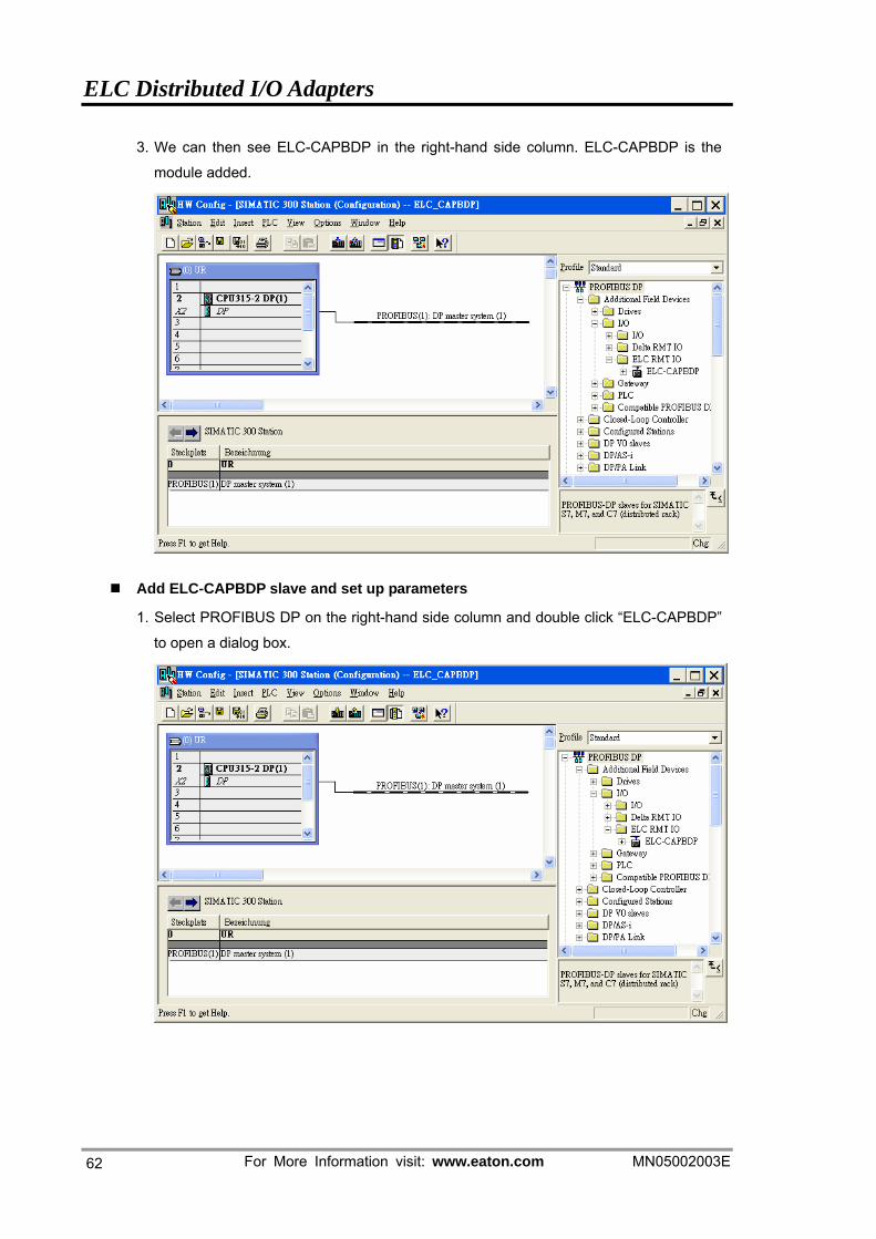
3. We can then see ELC-CAPBDP in the right-hand side column. ELC-CAPBDP is the
module added.
Add ELC-CAPBDP slave and set up parameters
1. Select PROFIBUS DP on the right-hand side column and double click “ELC-CAPBDP”
to open a dialog box.
ELC Distributed I/O Adapters
MN05002003E For More Information visit: www.eaton.com 63
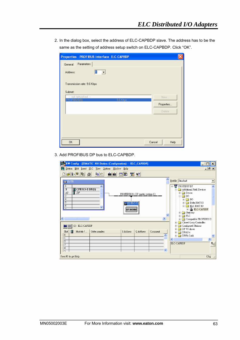
2. In the dialog box, select the address of ELC-CAPBDP slave. The address has to be the
same as the setting of address setup switch on ELC-CAPBDP. Click “OK”.
3. Add PROFIBUS DP bus to ELC-CAPBDP.
ELC Distributed I/O Adapters
For More Information visit: www.eaton.com MN05002003E
64
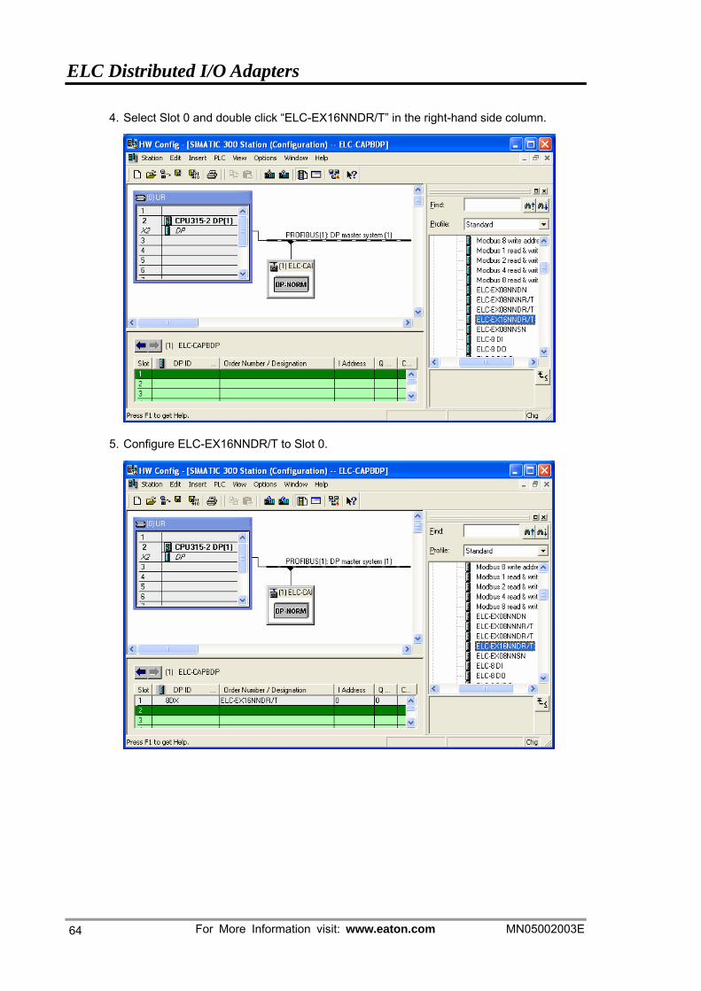
4. Select Slot 0 and double click “ELC-EX16NNDR/T” in the right-hand side column.
5. Configure ELC-EX16NNDR/T to Slot 0.
ELC Distributed I/O Adapters
MN05002003E For More Information visit: www.eaton.com 65
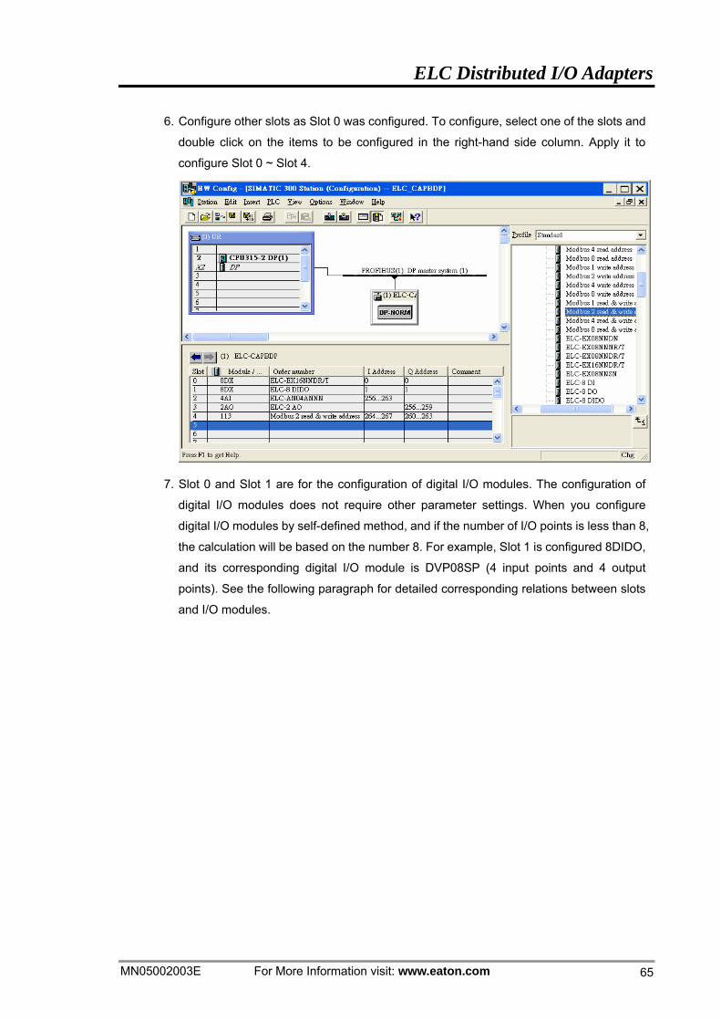
6. Configure other slots as Slot 0 was configured. To configure, select one of the slots and
double click on the items to be configured in the right-hand side column. Apply it to
configure Slot 0 ~ Slot 4.
7. Slot 0 and Slot 1 are for the configuration of digital I/O modules. The configuration of
digital I/O modules does not require other parameter settings. When you configure
digital I/O modules by self-defined method, and if the number of I/O points is less than 8,
the calculation will be based on the number 8. For example, Slot 1 is configured 8DIDO,
and its corresponding digital I/O module is DVP08SP (4 input points and 4 output
points). See the following paragraph for detailed corresponding relations between slots
and I/O modules.
ELC Distributed I/O Adapters
For More Information visit: www.eaton.com MN05002003E
66
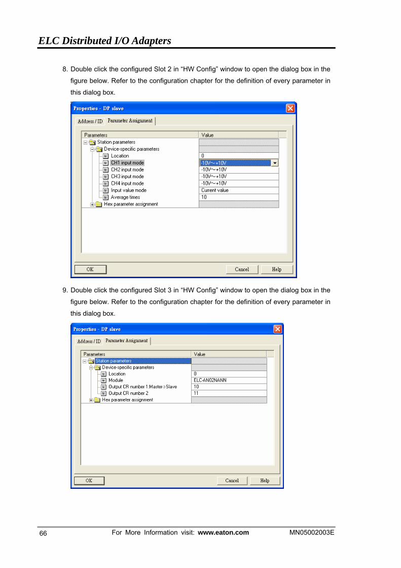
8. Double click the configured Slot 2 in “HW Config” window to open the dialog box in the
figure below. Refer to the configuration chapter for the definition of every parameter in
this dialog box.
9. Double click the configured Slot 3 in “HW Config” window to open the dialog box in the
figure below. Refer to the configuration chapter for the definition of every parameter in
this dialog box.
ELC Distributed I/O Adapters
MN05002003E For More Information visit: www.eaton.com 67
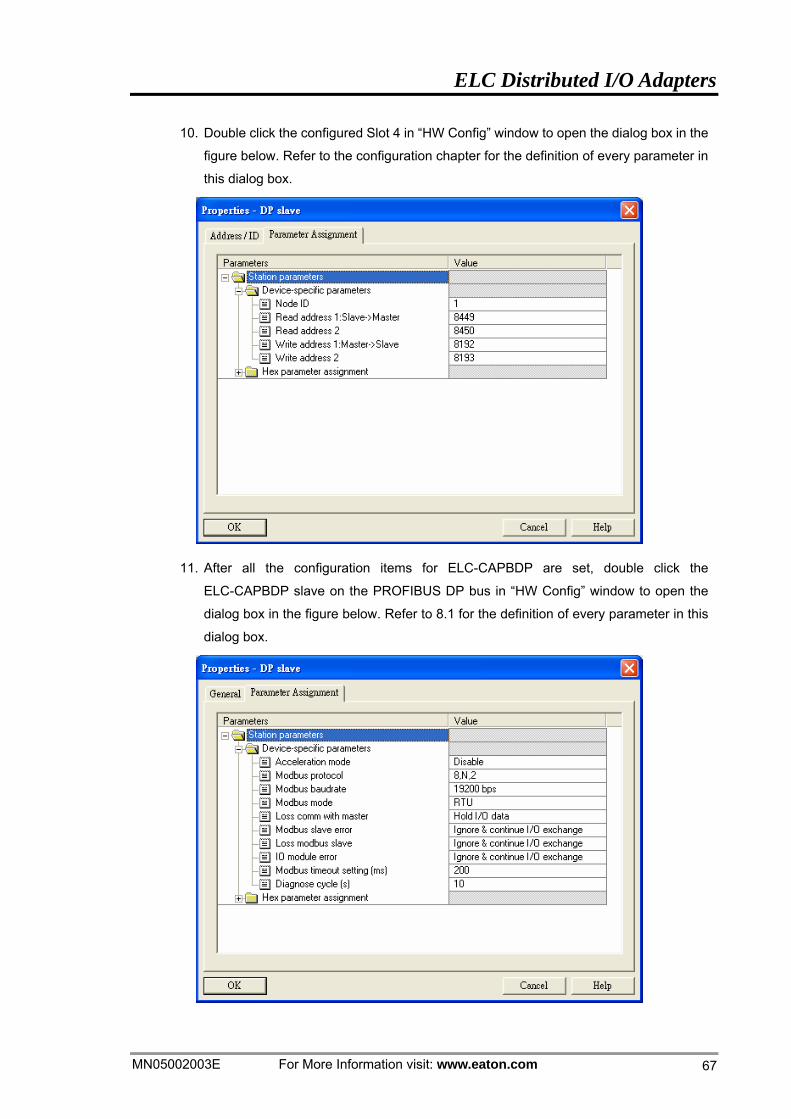
10. Double click the configured Slot 4 in “HW Config” window to open the dialog box in the
figure below. Refer to the configuration chapter for the definition of every parameter in
this dialog box.
11. After all the configuration items for ELC-CAPBDP are set, double click the
ELC-CAPBDP slave on the PROFIBUS DP bus in “HW Config” window to open the
dialog box in the figure below. Refer to 8.1 for the definition of every parameter in this
dialog box.
ELC Distributed I/O Adapters
For More Information visit: www.eaton.com MN05002003E
68
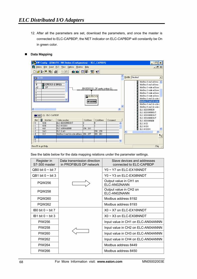
12. After all the parameters are set, download the parameters, and once the master is
connected to ELC-CAPBDP, the NET indicator on ELC-CAPBDP will constantly be On
in green color.
Data Mapping
See the table below for the data mapping relations under the parameter settings.
Register in S7-300 master
Data transmission direction in PROFIBUS DP network
Slave devices and addresses connected to ELC-CAPBDP
QB0 bit 0 ~ bit 7 Y0 ~ Y7 on ELC-EX16NNDT
QB1 bit 0 ~ bit 3 Y0 ~ Y3 on ELC-EX08NNDT
PQW256 Output value in CH1 on ELC-AN02NANN
PQW258 Output value in CH2 on ELC-AN02NANN
PQW260 Modbus address 8192
PQW262 Modbus address 8193
IB0 bit 0 ~ bit 7 X0 ~ X7 on ELC-EX16NNDT
IB1 bit 0 ~ bit 3 X0 ~ X3 on ELC-EX08NNDT
PIW256 Input value in CH1 on ELC-AN04ANNN
PIW258 Input value in CH2 on ELC-AN04ANNN
PIW260 Input value in CH3 on ELC-AN04ANNN
PIW262 Input value in CH4 on ELC-AN04ANNN
PIW264 Modbus address 8449
PIW266
Modbus address 8450
ELC Distributed I/O Adapters
MN05002003E For More Information visit: www.eaton.com 69
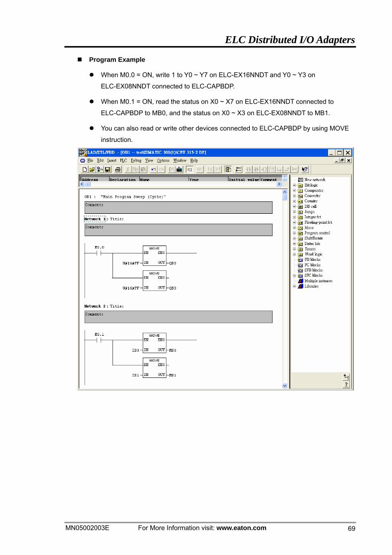
Program Example
When M0.0 = ON, write 1 to Y0 ~ Y7 on ELC-EX16NNDT and Y0 ~ Y3 on
ELC-EX08NNDT connected to ELC-CAPBDP.
When M0.1 = ON, read the status on X0 ~ X7 on ELC-EX16NNDT connected to
ELC-CAPBDP to MB0, and the status on X0 ~ X3 on ELC-EX08NNDT to MB1.
You can also read or write other devices connected to ELC-CAPBDP by using MOVE
instruction.