Embed Size (px)
Citation preview
ELEC4504/4906GAVIONICS SYSTEMS ENGINEERING
INTRODUCTION
• OBJECTIVES
• SOME HISTORY
• FACTORS AFFECTING AVIONICS DEVELOPMENT
COURSE OBJECTIVES
To provide the aeronautical engineering student with knowledge of:
1. The basic principles behind the avionics systems used in civil aircraft
2. The factors which should be taken into account when installing avionics in aircraft and
3. How the avionics systems are used in the operation of a commercial aircraft
COURSE OUTLINE
1. Organizational Framework
2. Air Traffic Control
CNS – Communications/ Navigation /Surveillance
3. The Electromagnetic Spectrum
4. Navigation
5. Precision Approach Systems
6. Communications Systems
7. Radar and Surveillance Systems
COURSE OUTLINE(CONTINUED)
8. Control Systems
9. Flight Management Systems
10. Display Systems
11. Electrical Systems
12. System Design
13. System Testing
14. Future Developments
Factors Affecting Avionics Development
1. Cost:
2. Number of systems in service
3. Benefits
4. Reliability
Sometimes it appears to take a long time to introduce new systems into service. There are several reasons for this
ORGANIZATIONAL FRAMEWORK
1. ICAO (International Civil Aviation Organization)
2. National Civil Aviation Organizations (FAA, CAA, Transport Canada).
3. RTCA
4. SAE
5. ARINC
6. EUROCAE
ORGANIZATIONAL FRAMEWORK
1. ICAO (International Civil Aviation Organization)
• Part of the United Nations
• Headquarters in Montreal
– Since civil aviation is an international activity, it is beneficial for all nations to use the same standards for most aspects of their aviation operations.
ICAO
– ICAO provides this service through documents called SARPS (standards and recommended practices)
– Examples of activities covered by SARPS are:
• Aircrew licensing
• Weather reports
• Flight plan forms
• Registration Markings
• Navigation Systems
ICAO
1. ICAO (Continued)
For example the SARPs on Navigation defines the characteristics of the Instrument Landing System (ILS) and includes:
• Signal strength
• Signal format
• Accuracy
• Coverage (distances at which usable signal can be detected)
ICAO
1. ICAO (Continued)
Note that all of these documents are recommendations only. Each country (or state) makes its own laws and rules
It is advantageous, however, for a country to follow these SARPS since non-standard practices discourage other countries from operating into such states.
ORGANIZATIONAL FRAMEWORK
2. RTCA (Requirements and Technical Concepts for Aviation)
Formerly known as the Radio Technical Committee for Aeronautics
and Radio Technical Commission for Aeronautics
• An example of the FAA’s practice of contracting out much of its technical work
• To understand the role of RTCA it is necessary to understand the FAA’s TSO (Technical Standard Order)
RTCA
• A given TSO is a minimum performance standard for a given piece of aircraft equipment (not restricted to avionics equipment)
• A TSO authorization is the FAA’s recognition that a given design meets the TSO and also authorizes the manufacturer to produce it.
• While the TSO authorization is not an approval to install the equipment it gives the equipment a very great advantage in obtaining certification for its installation
One of the first questions you are asked, if you want to install some equipment in an aircraft is “is it TSO’d?
Thus a TSO is very important
RTCA
• Q: Where do TSO’s come from?
• A: RTCA
When the FAA determines the need for a new piece of equipment e.g. a GPS receiver, it contacts the RTCA.
RTCA then establishes a committee (called a special committee) and invites anyone with any interest in the subject to join the committee. (airlines, equipment manufacturers, FAA officials, aircraft associations and international representatives)
GPS committee is SC-159
The committee produces a document called a MOPS (minimum operational performance standard) This is given a number preceded by DO
e.g. the MOPS for the GPS receiver is DO-208
RTCA
The RTCA MOPS is then submitted to the FAA which uses it as the basis for the TSO
The GPS receiver TSO is TSO-C129a
Thus the RTCA is a very powerful organization in the development of aircraft equipment (not just avionics)
ORGANIZATIONAL FRAMEWORK
ARINC (Aeronautical Radio Inc)
Started in the 1930’s by a group of airlines to provide communications between their aircraft and their bases.
It still provides this service through the ATN (Aeronautical Telecommunications Network) and ACARS (Aircraft Communications and Addressing System)
For avionics, however it is important for standardizing aircraft electronics boxes, trays and connectors.
Later it developed standards for aircraft digital data busses.

ARINC
ARINC (Aeronautical Radio Inc)
Started in the 1930’s by a group of airlines to provide communications between their aircraft and their bases.
It still provides this service through the ATN (Aeronautical Telecommunications Network) and ACARS (Aircraft Communications and Addressing System)
For avionics, however it is important for standardizing aircraft electronics boxes, trays and connectors.
ARINC
Electronic Equipment in aircraft has to be
• Firmly attached to the aircraft structure (by means of racks)
• Wired in to the aircraft systems
– Power
– Signals
– Controls
ARINC
Early Electronic Equipment was not standardized and hence the mounting systems and connectors were different not only for each piece of equipment but for the same equipment from different manufacturers
Thus upgrading equipment was expensive and time consuming
ARINC devised a set of standard “black box” sizes and corresponding mounting systems as well as connector designs.
ARINC
With standardized racks, boxes, trays and connectors, airlines could choose among various manufacturers of a particular item (e.g. Communications Transceiver) knowing that all they had to do was pull out the old set and plug in the new one.
ARINC
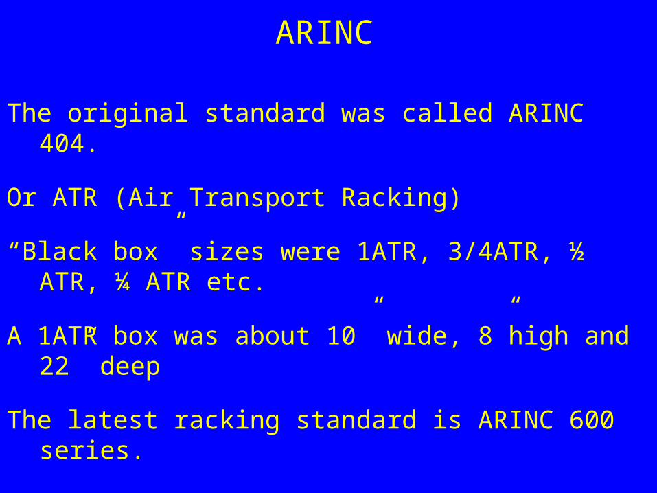
The original standard was called ARINC 404.
Or ATR (Air Transport Racking)
“Black box” sizes were 1ATR, 3/4ATR, ½ ATR, ¼ ATR etc.
A 1ATR box was about 10” wide, 8”high and 22” deep
The latest racking standard is ARINC 600 series.
ARINC
With the advent of digital communications in aircraft, ARINC developed popular digital data bus communications standards, primarily ARINC 429 and ARINC 629
SAE
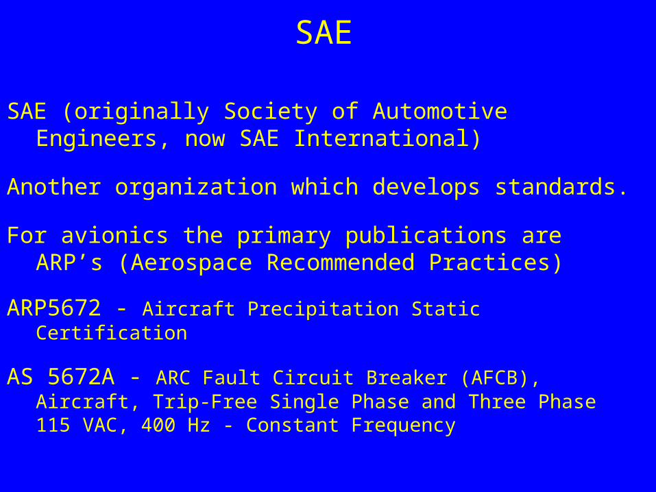
SAE (originally Society of Automotive Engineers, now SAE International)
Another organization which develops standards.
For avionics the primary publications are ARP’s (Aerospace Recommended Practices)
ARP5672 - Aircraft Precipitation Static Certification
AS 5672A - ARC Fault Circuit Breaker (AFCB), Aircraft, Trip-Free Single Phase and Three Phase 115 VAC, 400 Hz - Constant Frequency
EUROCAE
EUROCAE is essentially the European version of RTCA
The two organizations work closely together and publish joint standards.
AIR TRAFFIC CONTROL (ATC)AND ITS RELATIONSHIP TO
AVIONICS SYSTEMS
OBJECTIVES OF ATC
• Maintain separation of aircraft• Expedite the flow of Air Traffic• NOT responsible for the separation of aircraft
from the ground (except when in radar contact
RESPONSIBILITES OF THE PILOT (GENERAL)
Maintain aircraft ATTITUDENavigate the aircraft from departure to destinationAvoid collision with other aircraft
How these are accomplished depends on the weather(specifically ceiling and visibility)
VISUAL METEOROLOGICAL CONDITIONS (VMC)
Generally 3 miles visibility and 1000 Ft. ceiling
Visual Flight Rules (VFR) apply
– Attitude maintained by visual reference to the horizon
– Navigation by reference to the ground (or electronic aids if pilot is able to and aircraft is so equipped
– Separation from other aircraft by visual contact (see and be seen) Note: ATC will assist but is not responsible.
– Aircraft not allowed to enter cloud
VFR ON TOP
With extra training in radionavigation, pilots can fly in clear air above cloud
– Note: Attitude is still with reference to the visible horizon
– Climb and descent must not require entry into cloud
INSTRUMENT METEOROLOGICAL CONDITIONS (IMC)
IMC exist whenever VMC do not
Obviously the rules pertaining to IMC are IFR (Instrument Flight Rules)
IFR apply in IMC and also to all flight above 18000 Ft in Canada and the USA (other altitudes are specified in other countries)
INSTRUMENT FLIGHT RULES
Separation from other aircraft is responsibility of ATC
ATC issues “clearances” which are specific routes/altitudes which must be followed.
Attitude (pitch, bank and heading) is maintained with reference to instruments.
– Simplest: artificial horizon and compass– More complex: inertial navigation system
Navigation is done using electronic navigation aids
Two way communication is required between pilot and controller
ATC must know where aircraft is
– ATC radar requires a transponder on the aircraft
INSTRUMENT FLIGHT RULES
On-board Collision Avoidance Systems supplement ATC
Terrain Avoidance Systems provide protection from CFIT (Controlled Flight Into Terrain) when aircraft is out of radar coverage
Typical IFR Flight Procedure
Pilot plans route (including altitudes) from departure point to destination
Pilot files flight plan
ATC decides if flight plan can be accepted as is or if it needs to be amended
Prior to starting engines, pilot requests ATC clearance.
ATC gives clearance (may be just “flight planned route”)
Pilot contacts ground control for taxi clearance
Typical IFR Flight Procedure
Aircraft taxis to runwayTakeoff clearance is obtained from TowerAfter takeoff, pilot contacts Departure Control who gives “vectors” or a
series of headings and altitudes to guide aircraft to the start of the route to which it has been cleared
Near destination, Arrival Control provides vectors to the landing approach.
Tower gives clearance to landGround Control gives clearance to taxi to arrival gate