Embed Size (px)
Citation preview
8/2/2019 Elect WorkbenchMultisim_National Instruments Labview
http://slidepdf.com/reader/full/elect-workbenchmultisimnational-instruments-labview 1/4
Closing the Hardware Design Loop with Electronics WorkbenchMultisim and National Instruments LabVIEW
By Shauna L. Rae, Electronics Workbench, and Gretchen Edelmon, National Instrument
LabVIEW Multisim
Schematic Capture
Simulation
Data Acquisition
Automation
Sensors
Buses
Existing Designs
Actuators
Emulator Boards
Ultiboard
PCB Layout
Routing
Manufacturing Files
Completed PCB
Designers are always looking for ways
to improve their circuit simulations.
The combination of Electronics
Workbench Multisim and National Instruments LabVIEW allows
engineers to close the hardware design
loop. It provides designers with input
and feedback never before available,
allowing them to efficiently test and
verify both their circuits and
simulations.
Historically hardware design engineers
have simulated circuits with models that
are based on the electrical or physical
characteristics of the components. Thesesimulations have been very powerful and
helpful in the design and verification
process, but they are not withoutlimitations.
As designers continue to look for ways
to reduce time to market for newdesigns, the crossover point between the
design and the characterization and
validation process of actual hardware has
been neglected. By bridging betweenthe design and measurement area, users
can iterate more tightly through the
design process by identifying and
addressing discrepancies and addressingthem in the prototypes. The way to
accomplish this is to be able to reuse and
compare the signal data, simulated or measured, easily in either domain.
It has been difficult and time consuming
to accurately model real world signals
such as those from sensors or buses. Itwould be beneficial to capture these
signals and use them to drive
simulations. Simulation waveforms
could in turn be used to drive existing
interfaces to verify that the design isworking according to specifications. It
would also be useful to be able tocompare simulation waveforms to real
world waveforms in a direct format.
This would help to tighten simulations
and aid the debugging process.
This paper will provide a brief
introduction to Electronics Workbench
and their printed circuit board (PCB)
design and simulation tools and to
National Instruments with their
measurement products, includingmodular instruments and Data
Acquisition (DAQ) boards, programmed
using their LabVIEW product. It willshowcase how they work together and
highlight some general applications.
Printed Circuit Board Design
Electronics Workbench developsElectronics Design Automation (EDA)
tools for all major steps in the circuitdesign flow: schematic capture,simulation, PCB layout, autorouting, and
CAM preparation.
Designers use schematic capturesoftware to encapsulate their designs.
Once a design is captured, they can use
the schematic diagrams to drive
simulations and/or feed the PCB layout
and routing process.
Simulation programs are used to test and
verify designs. Simulation helpsdesigners to: reduce time to market, find
errors in their designs before they
become costly mistakes, evaluate
problems potentially caused byvariations in real world component
properties, and optimize their designs.
Once a design is verified at theschematic level, it must be placed and
routed for PCB production.
Multisim provides intuitive schematic
capture, SPICE, Verilog, VHDL, and RF
simulation, co-simulation, and analysisWith Ultiboard and Ultiroute, users
perform automatic or manual placemen
and routing of components and traces atthe PCB level. Ultiboard also outputs
manufacturing files.
Simulation with Multisim is powerfuyet easy-to-use. Virtual instrument
connect to wires in the schematic
diagram just like real world lab
instruments connect to wires in a circuitVirtual instruments in Multisim have
front panels and controls just like their
real world counterparts. If advanced
users want more control, they still haveaccess to traditional SPICE simulation
and analysis methods.
Circuit simulators are powerful tools thause models to represent the behaviour o
components. Alone, they do not have
the capability to capture or drive rea
world signals. Designers need to make
use of data acquisition and controdevices and associated application
software in order to do this. Unti
recently there was no easy way to dothis.
Virtual Instrumentation withLabVIEW
LabVIEW is the leading software
environment for data acquisition and
instrument control. With LabVIEW
8/2/2019 Elect WorkbenchMultisim_National Instruments Labview
http://slidepdf.com/reader/full/elect-workbenchmultisimnational-instruments-labview 2/4
users can acquire, analyze, and present
real-world data from plug-in dataacquisition boards, modular PXI
instruments, or traditional GPIB
instruments. LabVIEW is commonly
used to characterize circuit prototypes indesign labs. Designers can easily create
programs that generate analog and
digital stimulus signals for their boards,
and measure and analyze the responsesignals. These programs, called virtual
instruments, combine powerful
acquisition and analysis hardware andsoftware on a standard PC. Many of these systems use plug-in data
acquisition (DAQ) boards from National
Instruments, which enable users to
connect their circuits or sensors directlyto their computer for an integrated
measurement system.
LabVIEW is a complete programming
language, so users have the flexibility to
define exactly what they need – they are
not limited by the predefined
functionality of traditional GPIBinstruments. LabVIEW users combine
the measurement and analysis
components they need through software.The key to enabling scientists and
engineers to do this is through the
graphical programming language of
LabVIEW. LabVIEW is programmedusing block diagrams, rather than a
traditional text-based programming
language which can take years to master.Engineers can quickly assemble
programs by “wiring” together
functional blocks, or VIs, for performingacquisition, analysis, and display
functions in LabVIEW.
Integrating LabVIEW andMultisim
By combining the schematic capture,
simulation, and analysis tools available
in Multisim and the data acquisition andmeasurement features provided by
National Instruments DAQ devices andLabVIEW, real world analog and digital
signals are easily sampled and thenincorporated into simulations. This
means that designers can drive their
simulations, including HDL testbenches,
with data acquired from sensors, test points, or even data and address buses.
Designers can also import simulationresults from Multisim into LabVIEW.
There are two main reasons for doing
this. The first is to compare simulated
and real data and the second is to drive
external circuitry with simulation results.Both can significantly increase the
efficiency of the design verification
process.
National Instruments now provides pre-
built LabVIEW VIs that allow users to
read in and export data from and toMultisim. VIs compatible with
LabVIEW 6.1 are currently available and
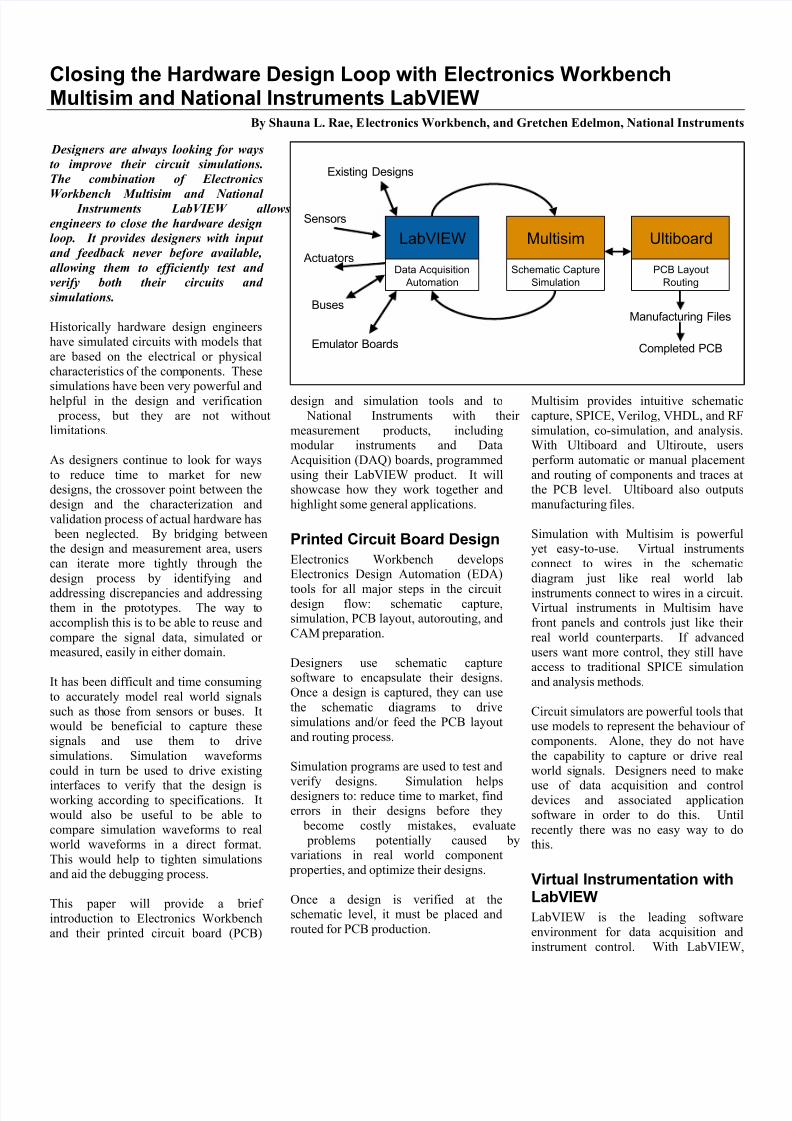
Express VIs are available for LabVIEW7.
The VIs for LabVIEW 7 take advantage
of a new feature called Express VIsExpress VIs are special VIs that allow
users to easily configure complex
operations through intuitiveconfiguration panels. Specifically, for
interfacing with Multisim, there are three
Express VIs: 1) Import from Multisim, 2
Resample Multisim Data, and 3) Expor
to Multisim.
The VIs serve one main purpose
Multisim and LabVIEW have differendefault data formats. Because of the
nature of SPICE simulation, Multisim
simulation data is not evenly spaced; it is
represented in the form of XY data pairs
LabVIEW data is uniformly distributedand each data set is represented first by
the delta value between two consecutive
data points and then the data points.
The Import from Multisim VI reads in
Multisim format simulation results into
LabVIEW without converting them tothe LabVIEW data format. In many
applications this is not a hindrance and
the XY pair data can be plotted directlyonto a graph. If the user wants to
perform advanced operations or analysi
in LabVIEW, they would need to use the Resample Multisim Data VI . This V
converts the XY data pairs into evenlydistributed LabVIEW format data.
The Export to Multisim VI converts the
data from LabVIEW format to theMultisim required XY data format and
saves it to a file. The user can then use
the Piecewise Linear Source in Multisimto read in LabVIEW data.
Possible Applications• Designs with sensors
• Designs that interfacewith existing circuitry
• Designs with bus
interfaces
• HDL designs
• Design reuse
• Debugging
8/2/2019 Elect WorkbenchMultisim_National Instruments Labview
http://slidepdf.com/reader/full/elect-workbenchmultisimnational-instruments-labview 3/4
Applications
Sampling Signals
As mentioned before, National
Instruments excels at capturing real
world signals and bringing them into acomputer for further processing. This is
helpful when you want to capture realworld output from sensors. It is the only
way that you can drive your circuitsimulations with sensor values that
would actually occur in the real world.
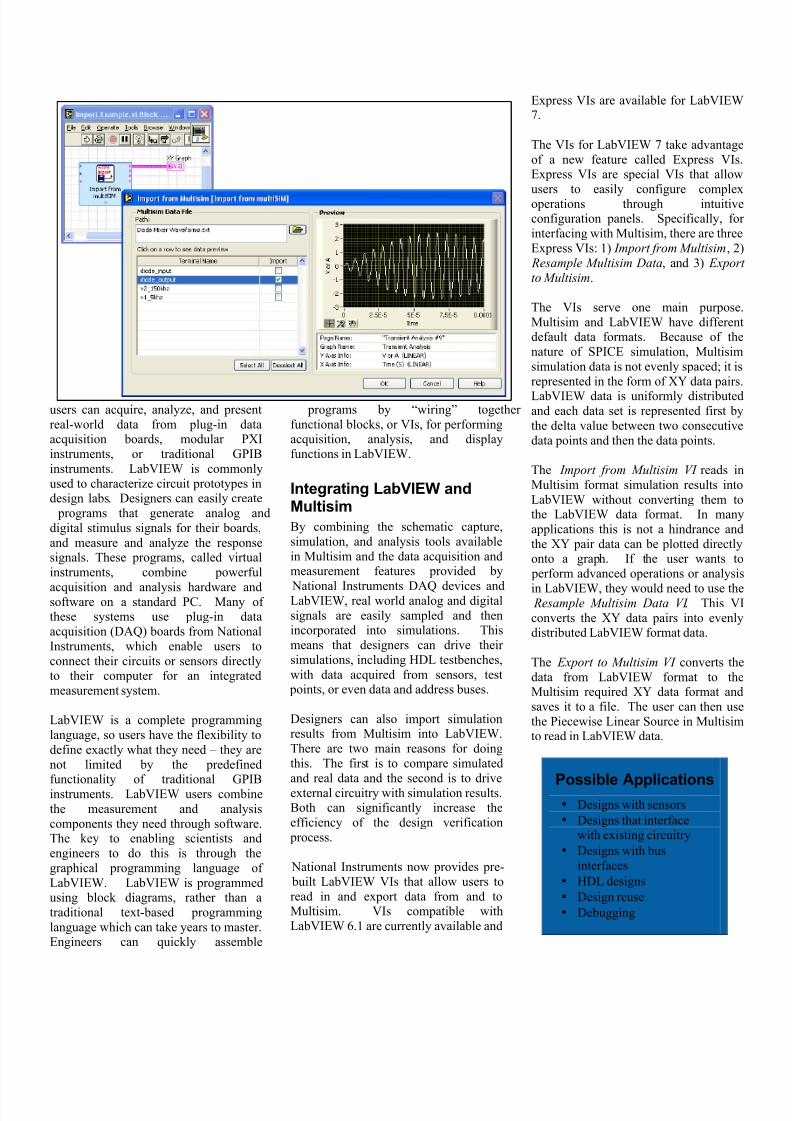
The integration between I/O Devices and
circuit simulation applications alsoenables users to accurately develop bus
or other digital signal interfaces.
Designers can sample actual read/writecycles from an existing bus. This allows
them to understand which lines of the
bus are relevant to the interface and
extract the critical timing informationwith a great deal more ease than looking
up and dissecting timing diagrams.
Many designs are not first generationdesigns, but rather modifications or
extensions of existing ones. There are
also a vast number of designs that
include modules from past designs.Using LabVIEW and Multisim designers
can accurately represent existing
circuitry in their simulations. This isextremely useful when portions of the
designs cannot be easily modelled for
simulation. The same applies to
prototypes of circuits and to signals from
microprocessor or microcontroller
emulator boards.
Because Multisim allows users to co-
simulate HDLs and SPICE, designers
can take advantage of this relationship tocreate real world HDL testbenches.
Comparing Simulation and Real
World Values
The relationship between the two
applications, LabVIEW and Multisim,
goes both ways. This means that noonly can users sample values but they
can also bring their simulation results
over to LabVIEW. This provides an
opportunity to easily compare simulationresults to real world waveforms. Some
of the benefits include increased
debugging efficiency, design
verification, and improving simulations.
Designers can cross reference the actua
performance of a system to the desired
performance. This can help them tracdown design or manufacturing errors
faster. It can also help designer
understand which simulation models are
too idealized and adjust themaccordingly.
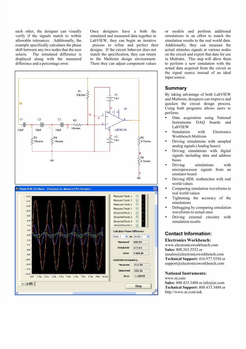
The following example illustrates this
concept. In this example, the actua performance of an operational amplifie
phase shift oscillator is compared to the
behaviour predicted by a simulation othe circuit. As shown in the schematic
diagram, this is a common operationa
amplifier circuit with three RC networks
in its feedback path. Each of these RC
networks introduces a 60° phase shif
thus producing the 180° phase shif
required for oscillation.
Two different aspects of circuit behavior
were simulated and then compared toactual data. Both of these comparisons
were made by first running a transienanalysis in Multisim to see the time
domain response of the oscillator and
then importing the simulated data into a
LabVIEW VI programmed to acquire thedata from the protoboard circuit.
The first comparison made in this
example is the oscillation frequencyThe circuit should oscillate at a specific
frequency based upon the RC network
values. The LabVIEW VI front panedisplays both the simulated frequencyvalue and the actual frequency
measurement and percentage of error
between the two values.
Secondly, the example plots the
simulated and measured waveforms from
four important nodes in the circuit: the
operational amplifier output and theoutput of each of the three RC networks
By plotting these waveforms along side
8/2/2019 Elect WorkbenchMultisim_National Instruments Labview
http://slidepdf.com/reader/full/elect-workbenchmultisimnational-instruments-labview 4/4
each other, the designer can visuallyverify if the signals match to within
allowable tolerances. Additionally, the
example specifically calculates the phase
shift between any two nodes that the user selects. The simulated difference is
displayed along with the measured
difference and a percentage error.
Once designers have a both thesimulated and measured data together in
LabVIEW, they can begin an iterative
process to refine and perfect their
designs. If the circuit behavior does notmatch the specification, they can return
to the Multisim design environment.
There they can adjust component values
or models and perform additionasimulations in an effort to match the
simulation results to the real world data
Additionally, they can measure the
actual stimulus signals at various nodeson the circuit and export that data for use
in Multisim. This step will allow them
to perform a new simulation with theactual data acquired from the circuit as
the signal source instead of an idea
input source.
Summary
By taking advantage of both LabVIEW
and Multisim, designers can improve and
quicken the circuit design processUsing both programs allows users to
perform:
• Data acquisition using Nationa
Instruments DAQ boards andLabVIEW
• Simulation with Electronics
Workbench Multisim
• Driving simulations with sampledanalog signals (Analog buses)
• Driving simulations with digita
signals including data and address
buses
• Driving simulations with
microprocessor signals from anemulator board
• Driving HDL testbenches with rea
world values• Comparing simulation waveforms to
real world values
• Tightening the accuracy of the
simulations
• Debugging by comparing simulationwaveforms to actual ones
• Driving external circuitry withsimulation results
Contact Information:
Electronics Workbench:
www.electronicsworkbench.comSales: 800.263.5552 or [email protected] Support: 416.977.5550 or
National Instruments:www.ni.comSales: 800.433.3488 or [email protected] Support: 800.433.3488 or http://www.ni.com/ask


![[0] LabVIEW de National Instruments CURSO Scada](https://img.pdfslide.net/doc/110x75/5571f8a149795991698dcb91/0-labview-de-national-instruments-curso-scada.jpg)