Embed Size (px)
Citation preview

AccuTemp Products, Inc. · 8415 North Clinton Park · Fort Wayne, IN 46825 ·800 210-5907 · accutemp.net
MP5004-1202
ELECTRIC GRIDDLE INSTALLATION & OWNERS MANUAL
Serial Number:Model:
Install Date:
Accu-Steam™ Installation and Owners ManialMP5004-1202 PAGE 1
TABLE OF CONTENTS
Instructions for Warranty Registration 2Startup Form 3Document History 4-5Safety Warnings Definition 6Safety Symbols Definiton 7Specification Model EGF 8-9Specification Model EGD 10Introduction 11Installation Model EGF 12-14Installation Model EGD 15-21Operation 22-23Cleaning 24-26Service and Troubleshooting 27-29Parts - Commercial 30-34Parts-Military 35-40Model EGF Schematics 41-45Model EGD Schematics 46-48Warranty 49
This manual is for AccuSteam Griddles Starting with:Model EGD Series S/N 7547 Model EGF Series S/N 7642
Accu-Steam™ Installation and Owners ManialMP5004-1202 PAGE 2
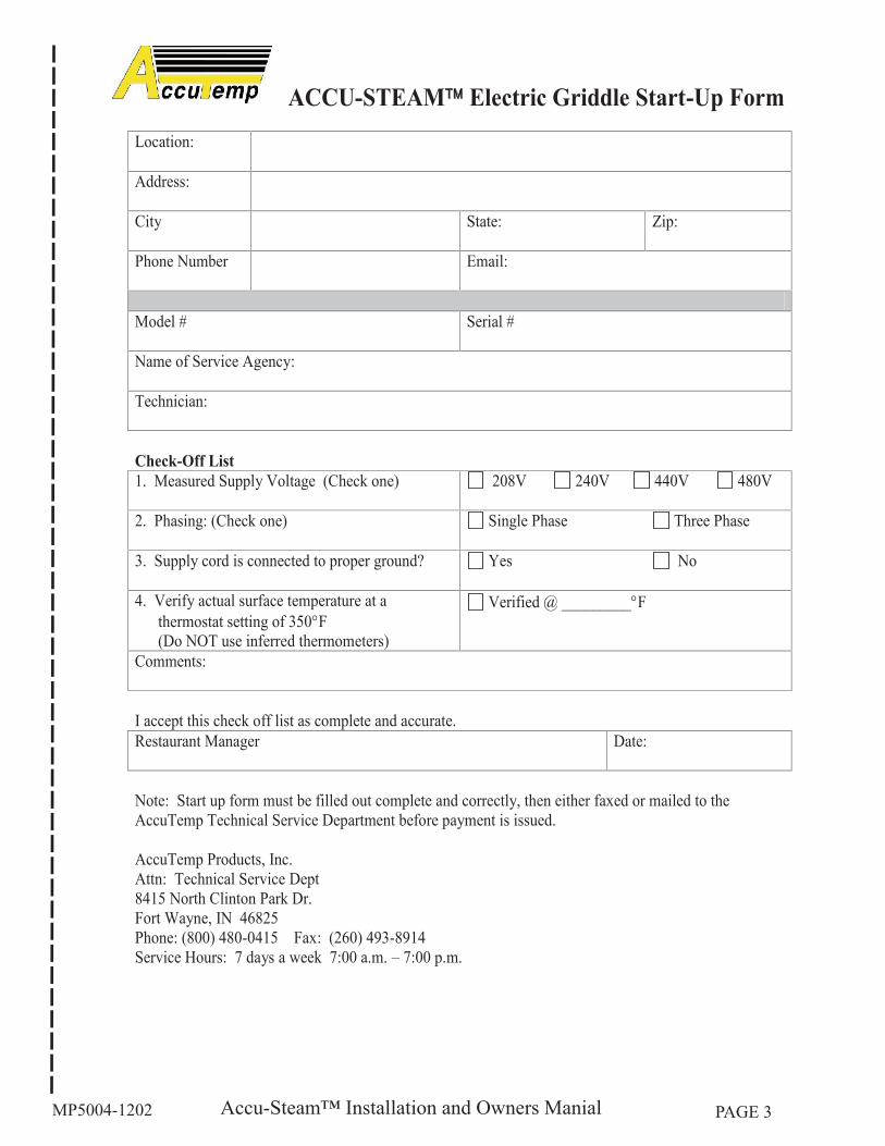
Before installing this appliance complete the following items:Fill in the warranty registration card that was enclosed in the documentation packet that came with the 1. appliance.Complete the startup checklist on page 2 of this manual.2. Mail, fax or email the warranty registration card and startup form to AccuTemp™.3.
If you have any questions please contact our technical service group. They are available 7 days a week from 7:00 am to 7:00 pm EST.
800 480-0415 Toll Free260 469-3040 Office260 469-3045 Fax
[email protected] emailwww.accutemp.net web site
Accu-Steam™ Installation and Owners ManialMP5004-1202 PAGE 3
Accu-Steam™ Installation and Owners ManialMP5004-1202 PAGE 4
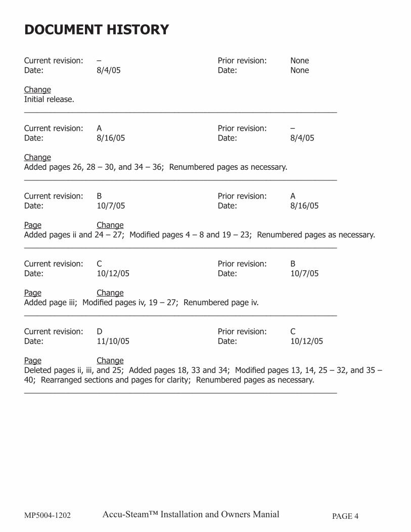
DOCUMENT HISTORY
Current revision: – Prior revision: NoneDate: 8/4/05 Date: None
ChangeInitial release._______________________________________________________________________
Current revision: A Prior revision: –Date: 8/16/05 Date: 8/4/05
ChangeAdded pages 26, 28 – 30, and 34 – 36; Renumbered pages as necessary._______________________________________________________________________
Current revision: B Prior revision: ADate: 10/7/05 Date: 8/16/05
Page ChangeAdded pages ii and 24 – 27; Modified pages 4 – 8 and 19 – 23; Renumbered pages as necessary._______________________________________________________________________
Current revision: C Prior revision: BDate: 10/12/05 Date: 10/7/05
Page ChangeAdded page iii; Modified pages iv, 19 – 27; Renumbered page iv._______________________________________________________________________
Current revision: D Prior revision: CDate: 11/10/05 Date: 10/12/05
Page ChangeDeleted pages ii, iii, and 25; Added pages 18, 33 and 34; Modified pages 13, 14, 25 – 32, and 35 – 40; Rearranged sections and pages for clarity; Renumbered pages as necessary._______________________________________________________________________
Accu-Steam™ Installation and Owners ManialMP5004-1202 PAGE 5
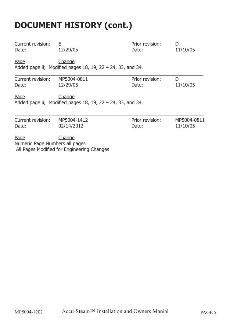
DOCUMENT HISTORY (cont.)
Current revision: E Prior revision: DDate: 12/29/05 Date: 11/10/05
Page ChangeAdded page ii; Modified pages 18, 19, 22 – 24, 33, and 34._______________________________________________________________________Current revision: MP5004-0811 Prior revision: DDate: 12/29/05 Date: 11/10/05
Page ChangeAdded page ii; Modified pages 18, 19, 22 – 24, 33, and 34.
Current revision: MP5004-1412 Prior revision: MP5004-0811Date: 02/14/2012 Date: 11/10/05
Page ChangeNumeric Page Numbers all pages All Pages Modified for Engineering Changes
Accu-Steam™ Installation and Owners ManialMP5004-1202 PAGE 6
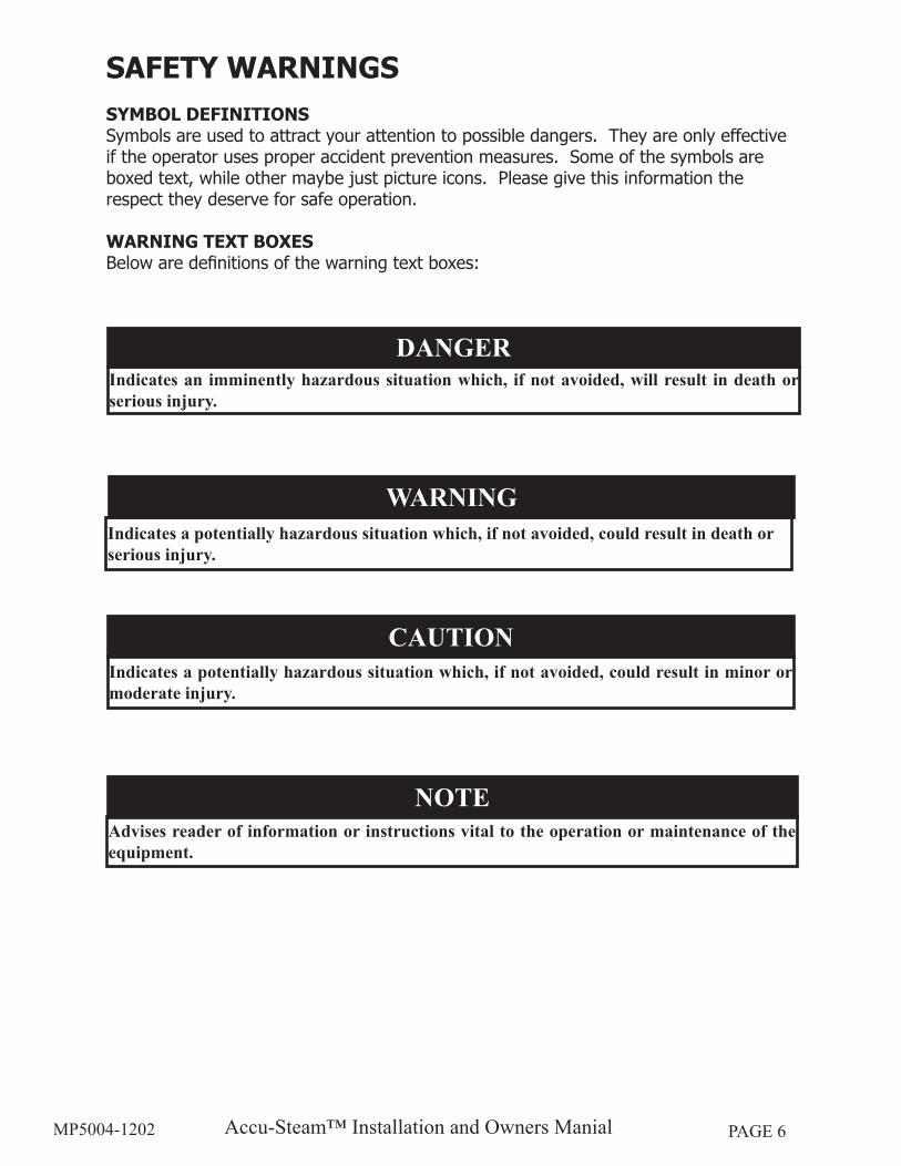
WARNINGIndicates a potentially hazardous situation which, if not avoided, could result in death or serious injury.
CAUTIONIndicates a potentially hazardous situation which, if not avoided, could result in minor or moderate injury.
NOTEAdvises reader of information or instructions vital to the operation or maintenance of the equipment.
SAFETY WARNINGSSYMBOL DEFINITIONSSymbols are used to attract your attention to possible dangers. They are only effective if the operator uses proper accident prevention measures. Some of the symbols are boxed text, while other maybe just picture icons. Please give this information the respect they deserve for safe operation.
WARNING TEXT BOXESBelow are definitions of the warning text boxes:
DANGERIndicates an imminently hazardous situation which, if not avoided, will result in death or serious injury.
Accu-Steam™ Installation and Owners ManialMP5004-1202 PAGE 7
SAFETY WARNINGS (cont.)
SYMBOL ICONSBelow are definitions of symbol icons used in this manual:
ALERT – Notifies the reader of an important message/warning, usually a safety related message.
INFORMATION – Notifies the reader of important information that may or may not be safety-related.
EARTH GROUND
DANGEROUS VOLTAGE
CAUTION, HOT SURFACE
Accu-Steam™ Installation and Owners ManialMP5004-1202 PAGE 8
RIGHT SIDE VIEW
TOP VIEW(2)Power CordProvided
Grease Trough
(A)
4 1/2"[114]
Control Panel
Grease Pan
(C)(Cooking Depth)
17 5/8"[448]
12 3/4" [323](Cooking Height)
(B)(Cooking Width)
Feet Standard
(D)Unit Depth
22 3/4" [578]Bullet Feet Footprint(E)
2 5/8”[66]
Griddle Width24”36”48”
Dim leg-to-leg20”32”44”
RIGHT SIDE VIEWEGF FLUSH MOUNT SERIES
8 1/4" [209](Cooking Height)
12 9/16"[319]
AccuTemp Products, Inc.
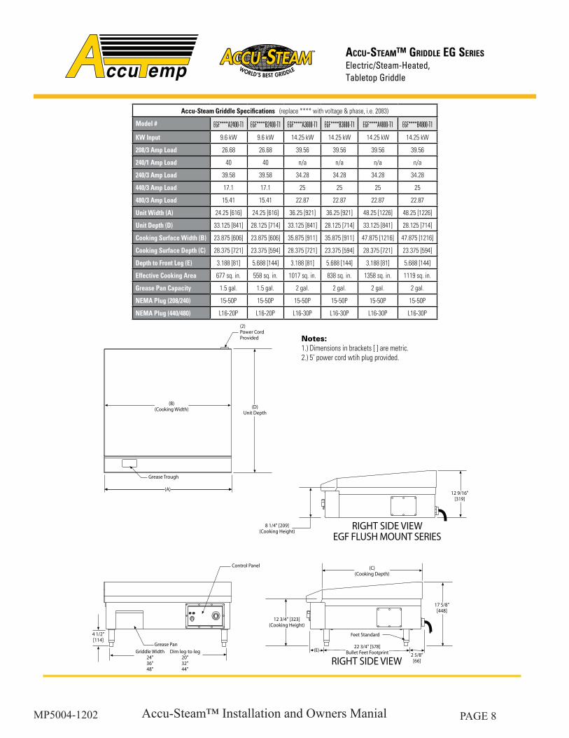
Accu-Steam Griddle Specifications (replace **** with voltage & phase, i.e. 2083)
Model # EGF****A2400-T1 EGF****B2400-T1 EGF****A3600-T1 EGF****B3600-T1 EGF****A4800-T1 EGF****B4800-T1
KW Input 9.6 kW 9.6 kW 14.25 kW 14.25 kW 14.25 kW 14.25 kW
208/3 Amp Load 26.68 26.68 39.56 39.56 39.56 39.56
240/1 Amp Load 40 40 n/a n/a n/a n/a
240/3 Amp Load 39.58 39.58 34.28 34.28 34.28 34.28
440/3 Amp Load 17.1 17.1 25 25 25 25
480/3 Amp Load 15.41 15.41 22.87 22.87 22.87 22.87
Unit Width (A) 24.25 [616] 24.25 [616] 36.25 [921] 36.25 [921] 48.25 [1226] 48.25 [1226]
Unit Depth (D) 33.125 [841] 28.125 [714] 33.125 [841] 28.125 [714] 33.125 [841] 28.125 [714]
Cooking Surface Width (B) 23.875 [606] 23.875 [606] 35.875 [911] 35.875 [911] 47.875 [1216] 47.875 [1216]
Cooking Surface Depth (C) 28.375 [721] 23.375 [594] 28.375 [721] 23.375 [594] 28.375 [721] 23.375 [594]
Depth to Front Leg (E) 3.188 [81] 5.688 [144] 3.188 [81] 5.688 [144] 3.188 [81] 5.688 [144]
Effective Cooking Area 677 sq. in. 558 sq. in. 1017 sq. in. 838 sq. in. 1358 sq. in. 1119 sq. in.
Grease Pan Capacity 1.5 gal. 1.5 gal. 2 gal. 2 gal. 2 gal. 2 gal.
NEMA Plug (208/240) 15-50P 15-50P 15-50P 15-50P 15-50P 15-50P
NEMA Plug (440/480) L16-20P L16-20P L16-30P L16-30P L16-30P L16-30P
ACCU-STEAM™ GRIDDLE EG SERIES
Notes:1.) Dimensions in brackets [ ] are metric.2.) 5’ power cord wtih plug provided.
Accu-Steam™ Installation and Owners ManialMP5004-1202 PAGE 9
AccuTemp Products, Inc.
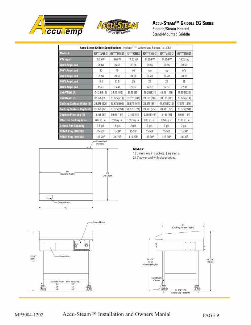
Accu-Steam Griddle Specifications (replace **** with voltage & phase, i.e. 2083)
Model # EGF****A2400-S2 EGF****B2400-S2 EGF****A3600-S2 EGF****B3600-S2 EGF****A4800-S2 EGF****B4800-S2
KW Input 9.6 kW 9.6 kW 14.25 kW 14.25 kW 14.25 kW 14.25 kW
208/3 Amp Load 26.68 26.68 39.56 39.56 39.56 39.56
240/1 Amp Load 40 40 n/a n/a n/a n/a
240/3 Amp Load 39.58 39.58 34.28 34.28 34.28 34.28
440/3 Amp Load 17.5 17.5 25 25 25 25
480/3 Amp Load 15.41 15.41 22.87 22.87 22.87 22.87
Unit Width (A) 24.25 [616] 24.25 [616] 36.25 [921] 36.25 [921] 48.25 [1226] 48.25 [1226]
Unit Depth (D) 33.125 [841] 28.125 [714] 33.125 [841] 28.125 [714] 33.125 [841] 28.125 [714]
Cooking Surface Width (B) 23.875 [606] 23.875 [606] 35.875 [911] 35.875 [911] 47.875 [1216] 47.875 [1216]
Cooking Surface Depth (C) 28.375 [721] 23.375 [594] 28.375 [721] 23.375 [594] 28.375 [721] 23.375 [594]
Depth to Front Leg (E) 3.188 [81] 5.688 [144] 3.188 [81] 5.688 [144] 3.188 [81] 5.688 [144]
Effective Cooking Area 677 sq. in. 558 sq. in. 1017 sq. in. 838 sq. in. 1358 sq. in. 1119 sq. in.
Grease Pan Capacity 1.5 gal. 1.5 gal. 2 gal. 2 gal. 2 gal. 2 gal.
NEMA Plug (208/240) 15-50P 15-50P 15-50P 15-50P 15-50P 15-50P
NEMA Plug (440/480) L16-20P L16-20P L16-30P L16-30P L16-30P L16-30P
ACCU-STEAM™ GRIDDLE EG SERIES
Notes:1.) Dimensions in brackets [ ] are metric.2.) 5’ power cord wtih plug provided.
(D)Unit Depth
(2)Power CordProvided
Grease Chute
(A)
(B)(Cooking Width)
(C)(Cooking Surface Depth)
40 7/16"[1028]
Control Panel
Grease Pan27 7/8"[709] 36 1/8"
[918](Cooking Height)
Stand WithCastersGriddle Width
24”36”48”
Dim leg-to-leg20”32”44” 22 3/4” [578]
Leg-to-Leg Footprint
Accu-Steam™ Installation and Owners ManialMP5004-1202 PAGE 10
35.50"[902mm]
1.625 - 4.125"[41 - 105mm]
6.50"[165mm]
(A)
(B)Cooking Surface Width
(C)Cooking Surface
Depth
29.50"[749mm]
8.87 - 11.0"[225 - 279mm]
See Note 2
1.31"[33]mm
1.5" [38mm]Depth To Cooking Surface
.73 - 2.63"[9 - 67mm]See Note 2
0" - 1.0"[0 - 25mm]
MM5207-0912
AccuTemp Products, Inc.
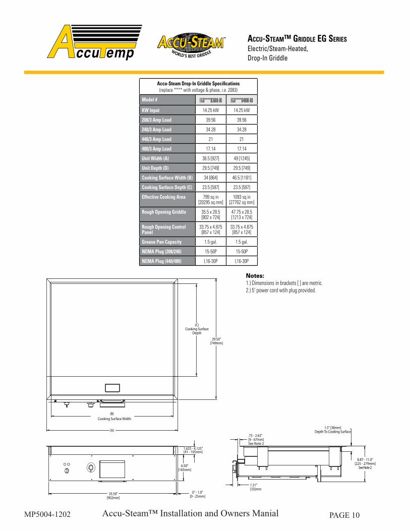
Accu-Steam Drop-In Griddle Specifications (replace **** with voltage & phase, i.e. 2083)
Model # EGD****B3600-00 EGD****B4800-00
KW Input 14.25 kW 14.25 kW
208/3 Amp Load 39.56 39.56
240/3 Amp Load 34.28 34.28
440/3 Amp Load 21 21
480/3 Amp Load 17.14 17.14
Unit Width (A) 36.5 [927] 49 [1245]
Unit Depth (D) 29.5 [749] 29.5 [749]
Cooking Surface Width (B) 34 [864] 46.5 [1181]
Cooking Surface Depth (C) 23.5 [597] 23.5 [597]
Effective Cooking Area 799 sq in[20295 sq mm]
1093 sq in[27762 sq mm]
Rough Opening Griddle 35.5 x 28.5[902 x 724]
47.75 x 28.5[1213 x 724]
Rough Opening Control Panel
33.75 x 4.875[857 x 124]
33.75 x 4.875[857 x 124]
Grease Pan Capacity 1.5 gal. 1.5 gal.
NEMA Plug (208/240) 15-50P 15-50P
NEMA Plug (440/480) L16-30P L16-30P
ACCU-STEAM™ GRIDDLE EG SERIES
Drop-In Griddle
Notes:1.) Dimensions in brackets [ ] are metric.2.) 5’ power cord wtih plug provided.
Accu-Steam™ Installation and Owners ManialMP5004-1202 PAGE 11
THEORY OF OPERATION
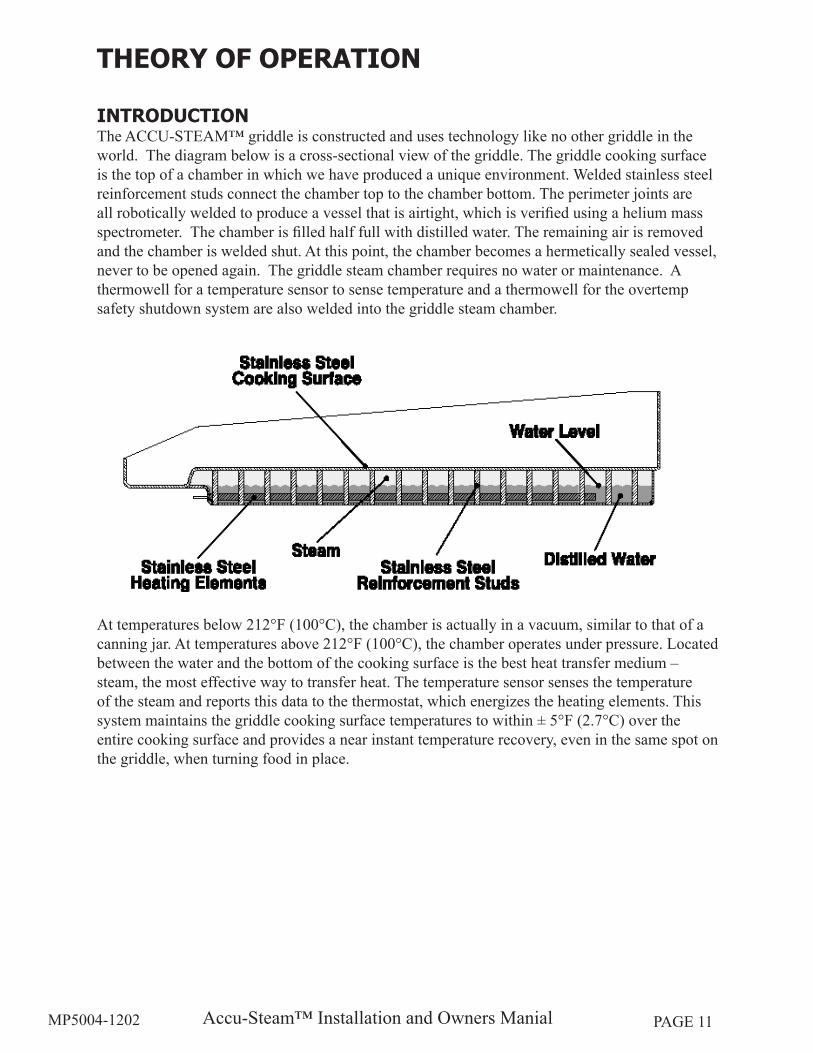
INTRODUCTIONThe ACCU-STEAM™ griddle is constructed and uses technology like no other griddle in the world. The diagram below is a cross-sectional view of the griddle. The griddle cooking surface is the top of a chamber in which we have produced a unique environment. Welded stainless steel reinforcement studs connect the chamber top to the chamber bottom. The perimeter joints are all robotically welded to produce a vessel that is airtight, which is verified using a helium mass spectrometer. The chamber is filled half full with distilled water. The remaining air is removed and the chamber is welded shut. At this point, the chamber becomes a hermetically sealed vessel, never to be opened again. The griddle steam chamber requires no water or maintenance. A thermowell for a temperature sensor to sense temperature and a thermowell for the overtemp safety shutdown system are also welded into the griddle steam chamber.
At temperatures below 212°F (100°C), the chamber is actually in a vacuum, similar to that of a canning jar. At temperatures above 212°F (100°C), the chamber operates under pressure. Located between the water and the bottom of the cooking surface is the best heat transfer medium – steam, the most effective way to transfer heat. The temperature sensor senses the temperature of the steam and reports this data to the thermostat, which energizes the heating elements. This system maintains the griddle cooking surface temperatures to within ± 5°F (2.7°C) over the entire cooking surface and provides a near instant temperature recovery, even in the same spot on the griddle, when turning food in place.
Accu-Steam™ Installation and Owners ManialMP5004-1202 PAGE 12
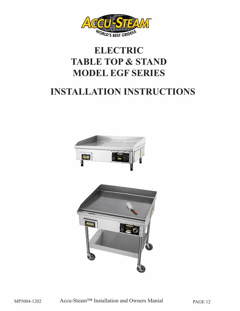
ELECTRIC TABLE TOP & STANDMODEL EGF SERIES
INSTALLATION INSTRUCTIONS
Accu-Steam™ Installation and Owners ManialMP5004-1202 PAGE 13
INSTALLATION TABLE TOP/STAND MODEL - EGF SERIES
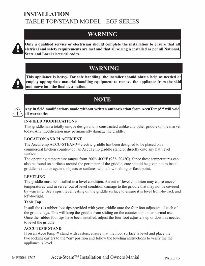
LOCATION AND PLACEMENTThe AccuTemp ACCU-STEAM™ electric griddle has been designed to be placed on a commercial kitchen counter-top, an AccuTemp griddle stand or directly onto any flat, level surface.The operating temperature ranges from 200°- 400°F (93°- 204°C). Since these temperatures can also be found on surfaces around the perimeter of the griddle, care should be given not to install griddle next to or against, objects or surfaces with a low melting or flash point.
LEVELING The griddle must be installed in a level condition. An out-of-level condition may cause uneven temperatures and in server out of level condition damage to the griddle that may not be covered by warranty. Use a spirit level resting on the griddle surface to ensure it is level front-to-back and left-to-right.Table TopInstall the (4) rubber foot tips provided with your griddle onto the four foot adjusters of each of the griddle legs. This will keep the griddle from sliding on the counter-top under normal use. Once the rubber foot tips have been installed, adjust the four foot adjusters up or down as needed to level the griddle.ACCUTEMP STAND If on an AccuTemp™ stand with casters, ensure that the floor surface is level and place the two locking casters to the “on” position and follow the leveling instructions to verify the the appliance is level.
IN-FIELD MODIFICATIONSThis griddle has a totally unique design and is constructed unlike any other griddle on the market today. Any modification may permanently damage the griddle.
Only a qualified service or electrician should complete the installation to ensure that all eletrical and safety requirements are met and that all wiring is installed as per all National, State and Local electrical codes.
WARNING
This appliance is heavy. For safe handling, the installer should obtain help as needed or employ appropriate material handling equipment to remove the appliance from the skid and move into the final destination.
WARNING
Any in field modifications made without written authorization from AccuTemp™ will void all warranties
NOTE
Accu-Steam™ Installation and Owners ManialMP5004-1202 PAGE 14
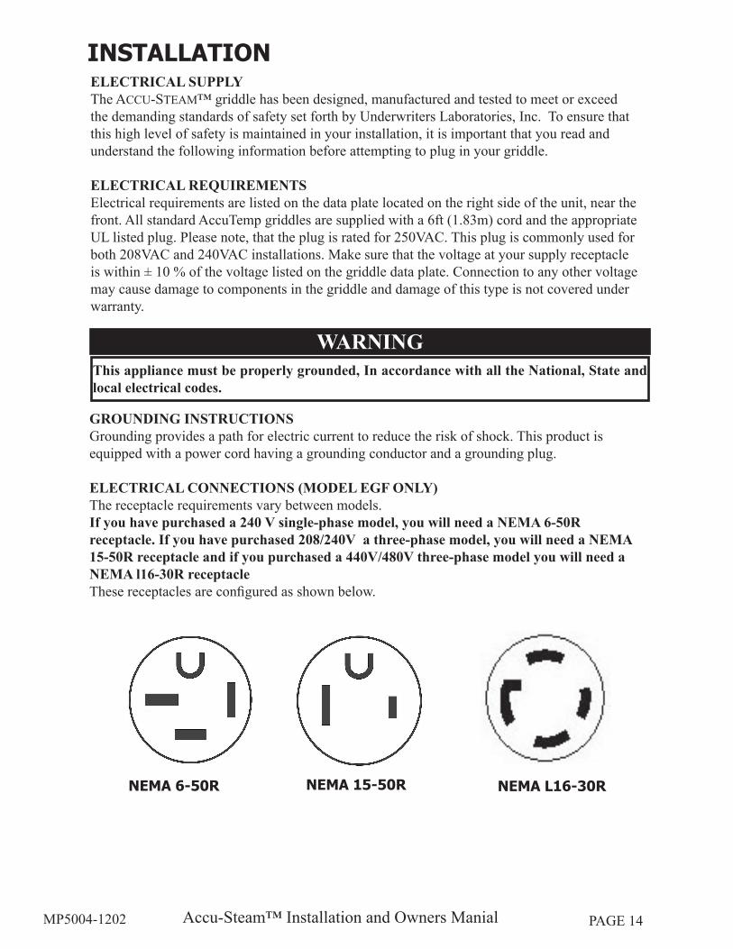
NEMA 6-50R NEMA 15-50R NEMA L16-30R
INSTALLATION
This appliance must be properly grounded, In accordance with all the National, State and local electrical codes.
WARNING
ELECTRICAL SUPPLYThe ACCU-STEAM™ griddle has been designed, manufactured and tested to meet or exceed the demanding standards of safety set forth by Underwriters Laboratories, Inc. To ensure that this high level of safety is maintained in your installation, it is important that you read and understand the following information before attempting to plug in your griddle.
ELECTRICAL REQUIREMENTSElectrical requirements are listed on the data plate located on the right side of the unit, near the front. All standard AccuTemp griddles are supplied with a 6ft (1.83m) cord and the appropriate UL listed plug. Please note, that the plug is rated for 250VAC. This plug is commonly used for both 208VAC and 240VAC installations. Make sure that the voltage at your supply receptacle is within ± 10 % of the voltage listed on the griddle data plate. Connection to any other voltage may cause damage to components in the griddle and damage of this type is not covered under warranty.
GROUNDING INSTRUCTIONSGrounding provides a path for electric current to reduce the risk of shock. This product is equipped with a power cord having a grounding conductor and a grounding plug.
ELECTRICAL CONNECTIONS (MODEL EGF ONLY)The receptacle requirements vary between models. If you have purchased a 240 V single-phase model, you will need a NEMA 6-50R receptacle. If you have purchased 208/240V a three-phase model, you will need a NEMA 15-50R receptacle and if you purchased a 440V/480V three-phase model you will need a NEMA l16-30R receptacleThese receptacles are configured as shown below.
Accu-Steam™ Installation and Owners ManialMP5004-1202 PAGE 15
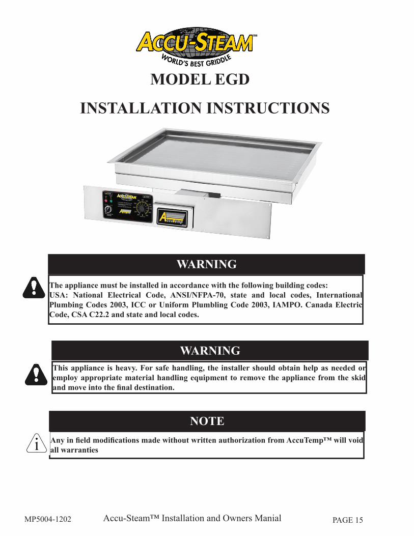
MODEL EGD
INSTALLATION INSTRUCTIONS
This appliance is heavy. For safe handling, the installer should obtain help as needed or employ appropriate material handling equipment to remove the appliance from the skid and move into the final destination.
WARNING
Any in field modifications made without written authorization from AccuTemp™ will void all warranties
NOTE
The appliance must be installed in accordance with the following building codes:USA: National Electrical Code, ANSI/NFPA-70, state and local codes, International Plumbing Codes 2003, ICC or Uniform Plumbling Code 2003, IAMPO. Canada Electric Code, CSA C22.2 and state and local codes.
WARNING
Accu-Steam™ Installation and Owners ManialMP5004-1202 PAGE 16
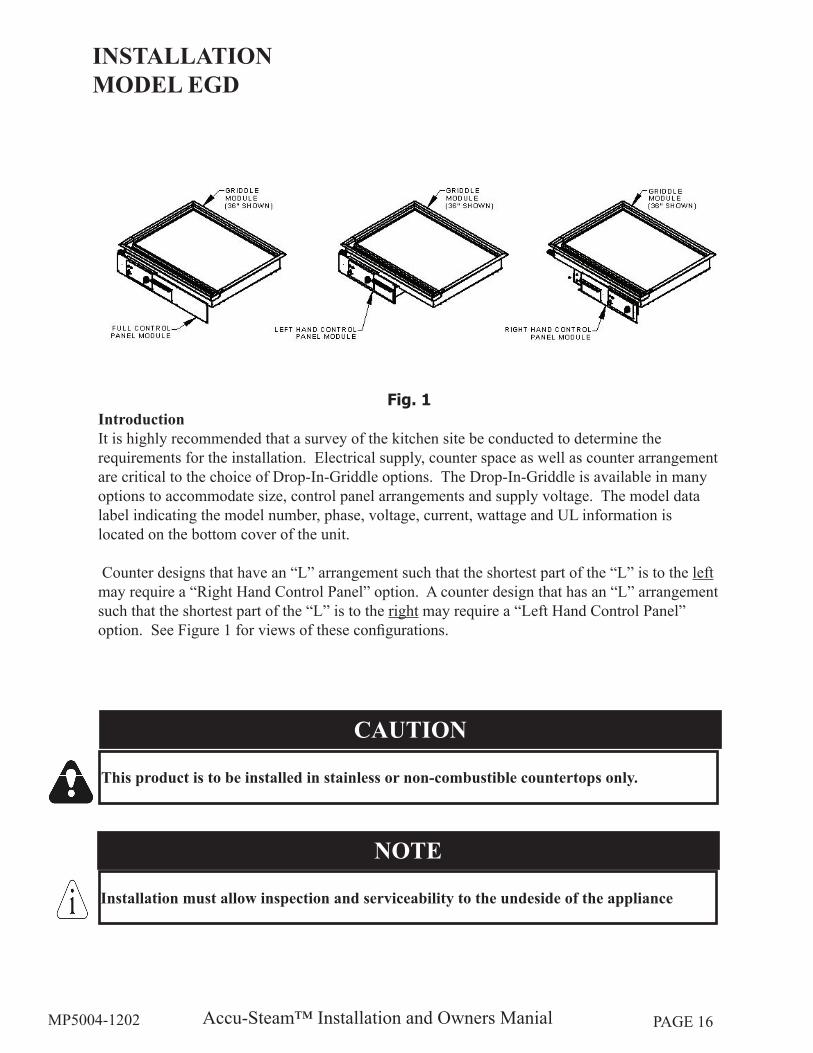
Fig. 1IntroductionIt is highly recommended that a survey of the kitchen site be conducted to determine the requirements for the installation. Electrical supply, counter space as well as counter arrangement are critical to the choice of Drop-In-Griddle options. The Drop-In-Griddle is available in many options to accommodate size, control panel arrangements and supply voltage. The model data label indicating the model number, phase, voltage, current, wattage and UL information is located on the bottom cover of the unit.
Counter designs that have an “L” arrangement such that the shortest part of the “L” is to the left may require a “Right Hand Control Panel” option. A counter design that has an “L” arrangement such that the shortest part of the “L” is to the right may require a “Left Hand Control Panel” option. See Figure 1 for views of these configurations.
INSTALLATION MODEL EGD
This product is to be installed in stainless or non-combustible countertops only.
CAUTION
Installation must allow inspection and serviceability to the undeside of the appliance
NOTE
Accu-Steam™ Installation and Owners ManialMP5004-1202 PAGE 17
INSTALLATION (cont.)MODEL EGD
ELECTRICAL SUPPLYThe ACCU-STEAM griddle has been designed, manufactured and tested to meet or exceed the demanding standards of safety set forth by Underwriters Laboratories, Inc. To ensure that this high level of safety is maintained in your installation, it is important that you read and understand the following information before attempting install your griddle.
ELECTRICAL REQUIREMENTSElectrical requirements are listed on the data plate located on the Bottom of the Control Box, near the front. The EGD Series griddles are supplied with a 5ft (1.52m) cord. Make sure that the voltage at your supply is within ± 10 % of the voltage listed on the griddle data plate. Connection to any other voltage may cause damage to components in the griddle and damage of this type is not covered under warranty.
This appliance must be properly grounded, in accordance with all National, State and local electrical codes.
WARNING
GROUNDING INSTRUCTIONSGrounding provides a path for electric current to reduce the risk of shock. This product is equipped with a power cord having a grounding conductor.
Accu-Steam™ Installation and Owners ManialMP5004-1202 PAGE 18
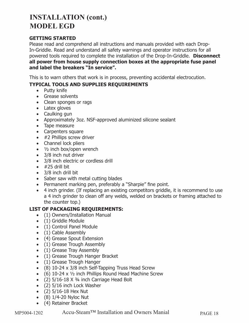
GETTING STARTEDPlease read and comprehend all instructions and manuals provided with each Drop-In-Griddle. Read and understand all safety warnings and operator instructions for all powered tools required to complete the installation of the Drop-In-Griddle. Disconnect all power from house supply connection boxes at the appropriate fuse panel and label the breakers “In service”.
This is to warn others that work is in process, preventing accidental electrocution.TYPICAL TOOLS AND SUPPLIES REQUIREMENTS
• Putty knife• Grease solvents• Clean sponges or rags• Latex gloves• Caulking gun• Approximately 3oz. NSF-approved aluminized silicone sealant• Tape measure• Carpenters square• #2 Phillips screw driver• Channel lock pliers• ½ inch box/open wrench• 3/8 inch nut driver• 3/8 inch electric or cordless drill• #25 drill bit• 3/8 inch drill bit• Saber saw with metal cutting blades• Permanent marking pen, preferably a “Sharpie” fine point. • 4 inch grinder. (If replacing an existing competitors griddle, it is recommend to use
a 4 inch grinder to clean off any welds, welded on brackets or framing attached to the counter top.)
LIST OF PACKAGING REQUIREMENTS:• (1) Owners/Installation Manual• (1) Griddle Module• (1) Control Panel Module• (1) Cable Assembly• (4) Grease Spout Extension• (1) Grease Trough Assembly• (1) Grease Tray Assembly• (1) Grease Trough Hanger Bracket• (1) Grease Trough Hanger• (8) 10-24 x 3/8 inch Self-Tapping Truss Head Screw• (6) 10-24 x ½ inch Phillips Round Head Machine Screw• (2) 5/16-18 X ¾ inch Carriage Head Bolt• (2) 5/16 inch Lock Washer• (2) 5/16-18 Hex Nut• (8) 1/4-20 Nyloc Nut• (4) Retainer Bracket
INSTALLATION (cont.)MODEL EGD
Accu-Steam™ Installation and Owners ManialMP5004-1202 PAGE 19
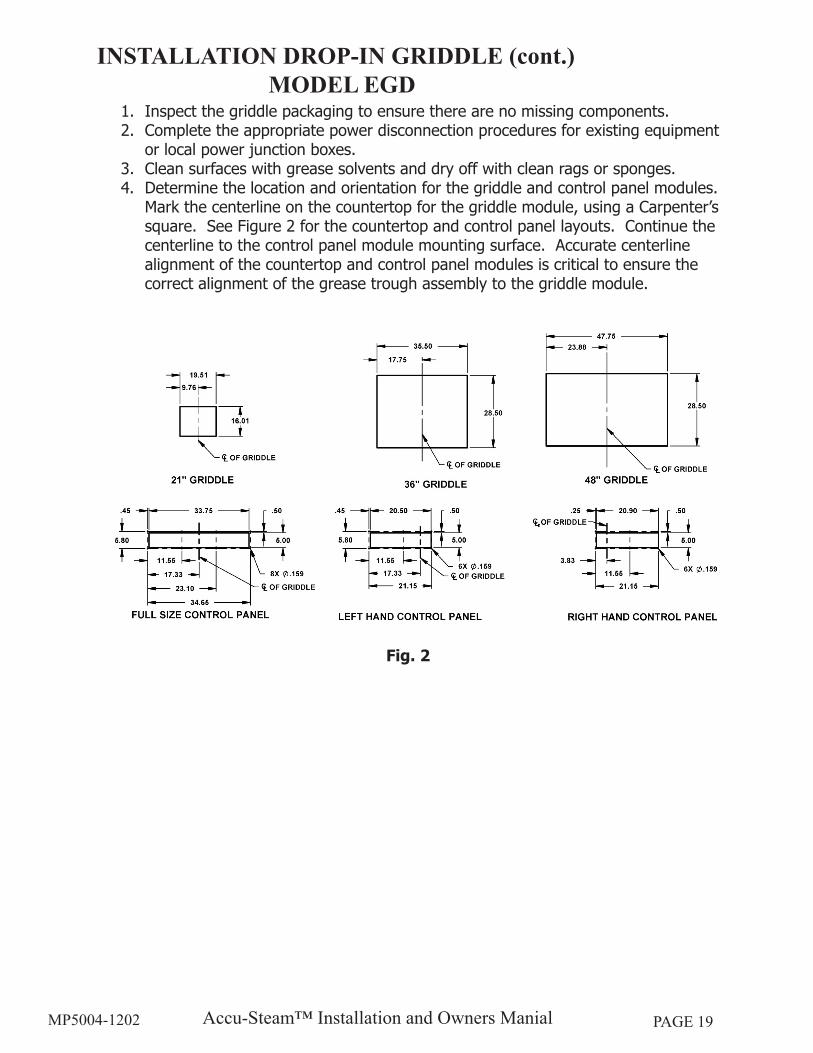
1. Inspect the griddle packaging to ensure there are no missing components.2. Complete the appropriate power disconnection procedures for existing equipment
or local power junction boxes.3. Clean surfaces with grease solvents and dry off with clean rags or sponges.4. Determine the location and orientation for the griddle and control panel modules.
Mark the centerline on the countertop for the griddle module, using a Carpenter’s square. See Figure 2 for the countertop and control panel layouts. Continue the centerline to the control panel module mounting surface. Accurate centerline alignment of the countertop and control panel modules is critical to ensure the correct alignment of the grease trough assembly to the griddle module.
Fig. 2
INSTALLATION DROP-IN GRIDDLE (cont.)MODEL EGD
Accu-Steam™ Installation and Owners ManialMP5004-1202 PAGE 20
INSTALLATION PROCEDURE
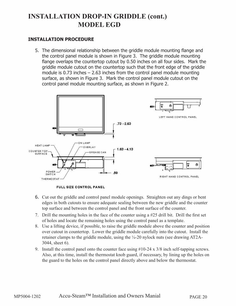
5. The dimensional relationship between the griddle module mounting flange and the control panel module is shown in Figure 3. The griddle module mounting flange overlaps the countertop cutout by 0.50 inches on all four sides. Mark the griddle module cutout on the countertop such that the front edge of the griddle module is 0.73 inches – 2.63 inches from the control panel module mounting surface, as shown in Figure 3. Mark the control panel module cutout on the control panel module mounting surface, as shown in Figure 2.
6. Cut out the griddle and control panel module openings. Straighten out any dings or bent edges in both cutouts to ensure adequate sealing between the new griddle and the counter top surface and between the control panel and the front surface of the counter.
7. Drill the mounting holes in the face of the counter using a #25 drill bit. Drill the first set of holes and locate the remaining holes using the control panel as a template.
8. Use a lifting device, if possible, to raise the griddle module above the counter and position over cutout in countertop. Lower the griddle module carefully into the cutout. Install the retainer clamps to the griddle module, using the ¼-20 nylock nuts (see drawing AT2A-3044, sheet 6).
9. Install the control panel onto the counter face using #10-24 x 3/8 inch self-tapping screws. Also, at this time, install the thermostat knob guard, if necessary, by lining up the holes on the guard to the holes on the control panel directly above and below the thermostat.
INSTALLATION DROP-IN GRIDDLE (cont.)MODEL EGD
Accu-Steam™ Installation and Owners ManialMP5004-1202 PAGE 21
10. Install the grease trough hanger brackets onto the bottom side of the griddle using (2) #10-24 X ½ inch Phillips round head machine screws and (2) 5/16-18 X ¾ inch carriage head bolts with (2) 5/16 inch lock washers and (2) 5/16-18 nuts (see drawing AT2A-3044, sheet 6). Leave the carriage bolts loose for adjustment of the grease trough.
11. Install the grease trough using (4) #10-24 X ½ inch Phillips round head machine screws through the front panel opening and through the hanger bracket assembly, installed in step 10.
12. Adjust the hanger bracket height so that the grease trough is setting level front-to-back and tighten the 5/16-18 nuts.
13. Install the appropriate size grease spout extension onto the griddle grease spout, that ensures the bottom of the grease spout extension is flush to the inside surface of the grease trough assembly (see drawing AT2A-3044, sheet 6).
14. Use the caulking gun to lay a 1/8” minimum diameter bead of the aluminized silicone sealant around the griddle module mounting flange onto the counter top. Use a gloved finger to wipe the sealant into a fillet shape.
15. Install the interconnect cable between the control panel module and the control box, mounted on the bottom side of the griddle (see drawing AT2A-3044, sheet 6).
16. Set the on/off switch to the off position and set the temperature control knob to the lowest setting.
17. Install the power cord into an appropriate sized electrical connection box with an appropriate sized cord grip or cable strain relief. Complete the final connections, testing the house supply wire first to ensure it is not live.
18. Turn on power to the griddle at the fuse panel.19.Turn the griddle on and set the temperature control knob to a desired setting. Wait
a minimum of 20 minutes. Then use a suitable temperature-measuring device to check the griddle surface temperature. The surface temperature should be within 5 – 7 °F of the temperature control knob setting. If it is not, go to the calibration section and follow the calibration procedures.
20.This completes the drop-in griddle installation.
INSTALLATION DROP-IN GRIDDLE (cont.)MODEL EGD
Accu-Steam™ Installation and Owners ManialMP5004-1202 PAGE 22
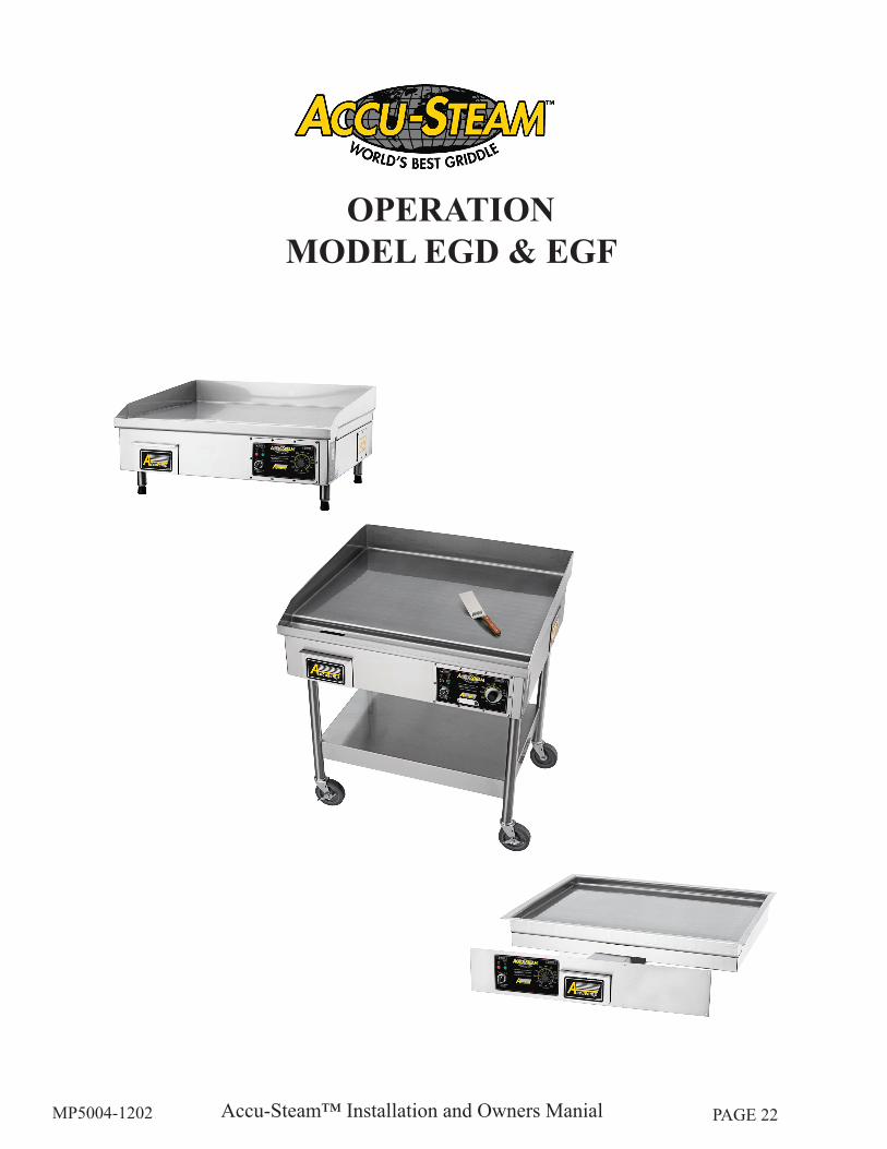
OPERATIONMODEL EGD & EGF
Accu-Steam™ Installation and Owners ManialMP5004-1202 PAGE 23
SEASONINGIt is recommended that you clean your ACCU-STEAM™ griddle thoroughly before turning your unit on. To clean the griddle surface, just simply wash the cooking surface down with a solution of mild soap and water, and then rinse thoroughly with clean water. Once the cooking surface has been cleaned, set the thermostat to 200°F (93°C), turn the griddle power switch to the “On” position and allow the griddle cooking surface to heat for 10 minutes. Using a high temperature oil, such as Pan and Grill Shortening™, Whirl™ or equivalent, pour enough to cover the entire griddle surface. Do not use standard vegetable oil to season the griddle cooking surface. It may cause food to stick and result in improperly cooked food. Work this seasoning oil into the griddle surface with a regular heavy-duty scrub pad for about 5 minutes, making sure that you scrub the seasoning oil over the entire griddle-cooking surface. After the entire griddle surface has been scrubbed with seasoning oil for 5 minutes, simply wipe or squeegee off excess oil from griddle surface. Your griddle is now ready to use!
If you use chemicals to clean your griddle periodically or on a schedule, you may need to repeat this process after the use of chemicals.
PREHEATINGTurn On switch to the “On” position and set the thermostat to the desired temperature. The griddle will increase its surface temperature at an average rate of 15° F (8°C) per minute. It takes approximately 22 minutes to raise the griddle from room temperature to its maximum temperature of 400° F (204°C). The griddle will be preheated when the “Heat” light starts to cycle on and off. Please use caution as temperatures on and around the griddle cooking surface could cause severe burns.COOKINGBegin cooking only after the griddle has been preheated to the desired temperature. Please note these facts:
• You can cook all the way to the edges of the griddle surface because the temperature does not very across the entire cooking surface.
• You can turn the product to the same spot because the griddle has near instant heat recovery.
• It will always cook the same, regardless of product load or surface coverage.Accurate Cooking TemperaturesBecause of the inaccurate surface temperatures and long recovery times common with other griddles. It is doubtful you were cooking at the set temperature or the temperature you wanted. Adjust the temperature on your ACCU-STEAM™ griddle and it will not change or vary by the location on the griddle surface. There are no hot or cold zones.Heat LampIt is normal for the heat light to cycle on and off. This light indicates when the heaters are energized. You will soon notice how little they are energized to maintain perfect surface temperatures on your griddle.
OPERATION
Accu-Steam™ Installation and Owners ManialMP5004-1202 PAGE 24
Grease PanUse caution when emptying the grease pan. The contents in this pan could cause severe burns. The pan should be checked periodically and emptied as necessary to prevent an overflow or dangerous condition.
OPERATION (cont.)
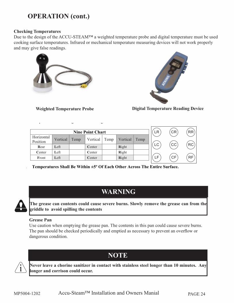
Checking TemperaturesDue to the design of the ACCU-STEAM™ a weighted temperature probe and digital temperature must be used cooking surface temperatures. Infrared or mechanical temperature measuring devices will not work properly and may give false readings.
Weighted Temperature Probe Digital Temperature Reading Device
AccuTemp Products, Inc.Technical Services
AccuTemp 1 Chamber IntegrityWWW.AccuTemp.Net
AccuTemp Products, Inc.Voice: 800 480-0415 • Fax: 260 493-8914
Chamber Integrity Nine Point Test
Warning:Do Not Use Infrared Instruments to measure temperatures. Infrared
instruments are inaccurate on stainless steel surfaces and may causeharm to person(s) using the instrument.
1. With griddle plugged in, set thermostat dial to 200ºF and turn ON.
2. Place temperature surface probe in the center in the first 1/3 of cooking surface; between theweld stud dimples.
3. Allow griddle to heat to initial setting.4. Increase thermostat setting to 300ºF.5. Allow griddle to cycle twice.6. For Surface Temperature Checks Only, Place Temperature Surface Probe and Record
Temperatures according to the following chart.
7. Temperatures Shall Be Within ±5º Of Each Other Across The Entire Surface.
7 April 2009AT Nine Point Test. Rev.C
Note:Temperature surface probe must be calibrated to
perform this check.
NotePut a small amount of cooking oil on the griddle cooking surface.
Temperatures shall be taken between the griddle weld stud dimples.
Nine Point ChartHorizontalPosition Vertical Temp Vertical Temp Vertical Temp
Rear Left Center RightCenter Left Center RightFront Left Center Right
Tools Required:Small Amount High TemperatureCooking Oil1 – Temperature Surface Probe
LF RFCF
LC RCCC
LR RRCR
The grease can contents could cause severe burns. Slowly remove the grease can from the griddle to avoid spilling the contents
WARNING
Never leave a chorine sanitizer in contact with stainless steel longer than 10 minutes. Any longer and corrison could occur.
NOTE
Accu-Steam™ Installation and Owners ManialMP5004-1202 PAGE 25
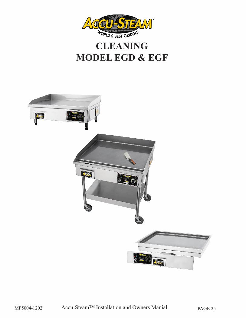
CLEANINGMODEL EGD & EGF
Accu-Steam™ Installation and Owners ManialMP5004-1202 PAGE 26
DAILY CLEANINGCleaning during the work shift can be performed with a sharp scraper. When heavy cleaning at the end of a shift or periodically as needed, the following is recommended:
• Turn the griddle off and allow it to cool to between 220°F and 240°F (104°F and 116°C). Use water, ice and/or griddle cleaner as needed. For example, the 3M Scotch-Brite™ Quick Clean Griddle System provides the Scotch-Brite polishing pads, quick clean liquid, pad holder and squeegee. Clean-up is very easy using these tools with the quick clean liquid, water, ice or combinations of these liquids. Seasoning the griddle after the daily cleaning is recommended.•
CAUTIONIf the cooking surface of the appliance has standing grease and the griddle is at a high temperature using water or ice can cause the grease to splatter and cause skin burns.
NOTEDo not use a appliance stome or brick to clean griddle cooking surface. Only use a fabric scrub pad.
NOTEDo not use a water-jet to clean the griddle as it can harn the electronic components in the appliance.
Accu-Steam™ Installation and Owners ManialMP5004-1202 PAGE 27
SERVICE & TROUBLESHOOTINGMODEL EGD & EGF
Accu-Steam™ Installation and Owners ManialMP5004-1202 PAGE 28
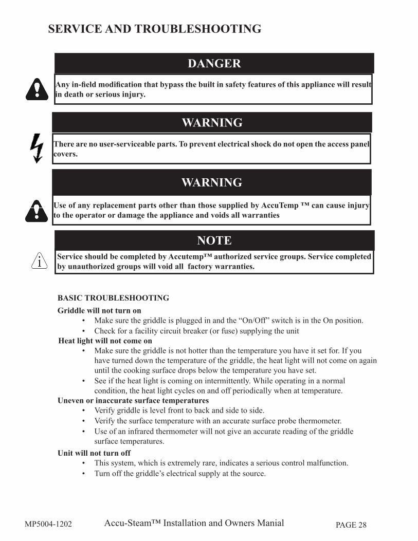
BASIC TROUBLESHOOTINGGriddle will not turn on
• Make sure the griddle is plugged in and the “On/Off” switch is in the On position.• Check for a facility circuit breaker (or fuse) supplying the unit
Heat light will not come on• Make sure the griddle is not hotter than the temperature you have it set for. If you
have turned down the temperature of the griddle, the heat light will not come on again until the cooking surface drops below the temperature you have set.
• See if the heat light is coming on intermittently. While operating in a normal condition, the heat light cycles on and off periodically when at temperature.
Uneven or inaccurate surface temperaturesVerify griddle is level front to back and side to side.• Verify the surface temperature with an accurate surface probe thermometer. • Use of an infrared thermometer will not give an accurate reading of the griddle • surface temperatures.
Unit will not turn off• This system, which is extremely rare, indicates a serious control malfunction. • Turn off the griddle’s electrical supply at the source.
SERVICE AND TROUBLESHOOTING
Use of any replacement parts other than those supplied by AccuTemp ™ can cause injury to the operator or damage the appliance and voids all warranties
WARNING
NOTEService should be completed by Accutemp™ authorized service groups. Service completed by unauthorized groups will void all factory warranties.
There are no user-serviceable parts. To prevent electrical shock do not open the access panel covers.
WARNING
Any in-field modification that bypass the built in safety features of this appliance will result in death or serious injury.
DANGER
Accu-Steam™ Installation and Owners ManialMP5004-1202 PAGE 29
WARRANTY PROCEDURE
An AccuTemp Products, Inc. Technical Service Technician is available: Monday thru Sunday, 7:00am to 7:00pm EST.
SERVICE AND TROUBLESHOOTING (cont.)
Contact the AccuTemp™ Technical Service group for all warranty service requests.1. Be prepared to supply the serial number, address, location phone and contact for the location.2. Be prepared to complete a few simple tasks to help evaluate the problem.3. If the problem requires service at the location the AccuTemp™ Technical Service group will 4. dispatch the nearest authorized service agent.
NOTEService should be completed by Accutemp™ authorized service groups. Service completed by unauthorized groups will void all factory warranties.
NOTEAccuTemp™ Technical Service group must be contacted for all warranty service requests or the warranty claim my be denied.
800 480-0415 Toll Free260 469-3040 Office260 469-3045 Fax
[email protected] emailwww.accutemp.net web site

Accu-Steam™ Installation and Owners ManialMP5004-1202 PAGE 30
PARTSCOMMERCIAL
Accu-Steam™ Installation and Owners ManialMP5004-1202 PAGE 31
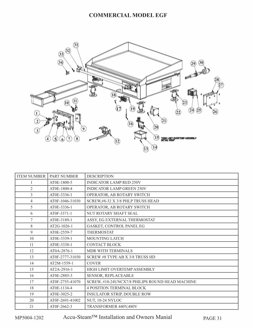
ITEM NUMBER PART NUMBER DESCRIPTION1 AT0E-1800-5 INDICATOR LAMP RED 250V2 AT0E-1800-4 INDICATOR LAMP GREEN 250V3 AT0E-3336-1 OPERATOR, AB ROTARY SWITCH4 AT0F-1046-31030 SCREW,#8-32 X 3/8 PHLP TRUSS HEAD5 AT0E-3336-1 OPERATOR, AB ROTARY SWITCH6 AT0F-3371-1 NUT ROTARY SHAFT SEAL7 AT0E-3189-1 ASSY, EG EXTERNAL THERMOSTAT8 AT2G-1026-1 GASKET, CONTROL PANEL EG9 AT0E-2559-7 THERMOSTAT10 AT0E-3339-1 MOUNTING LATCH11 AT0E-3338-1 CONTACT BLOCK12 AT0A-2876-1 MDR WITH TERMINALS13 AT0F-2777-31030 SCREW #8 TYPE AB X 3/8 TRUSS HD14 AT2M-1559-1 COVER15 AT2A-2916-1 HIGH LIMIT OVERTEMP ASSEMBLY16 AT0E-2885-3 SENSOR, REPLACEABLE17 AT0F-2755-41070 SCREW, #10-24UNCX7/8 PHILIPS ROUND HEAD MACHINE18 AT0E-1134-4 4 POSITION TERMINAL BLOCK19 AT0E-3025-2 INSULATOR STRIP, DOUBLE ROW20 AT0F-2691-41002 NUT, 10-24 NYLOC21 AT0F-2662-3 TRANSFORMER 440V,480V
1
3
2
4 5 6 7 8
9
10 11
13
15
1412
16
17 19
20
18
21
2422
23
2625
2827
29 30
3332
31
34
COMMERCIAL MODEL EGF
Accu-Steam™ Installation and Owners ManialMP5004-1202 PAGE 32
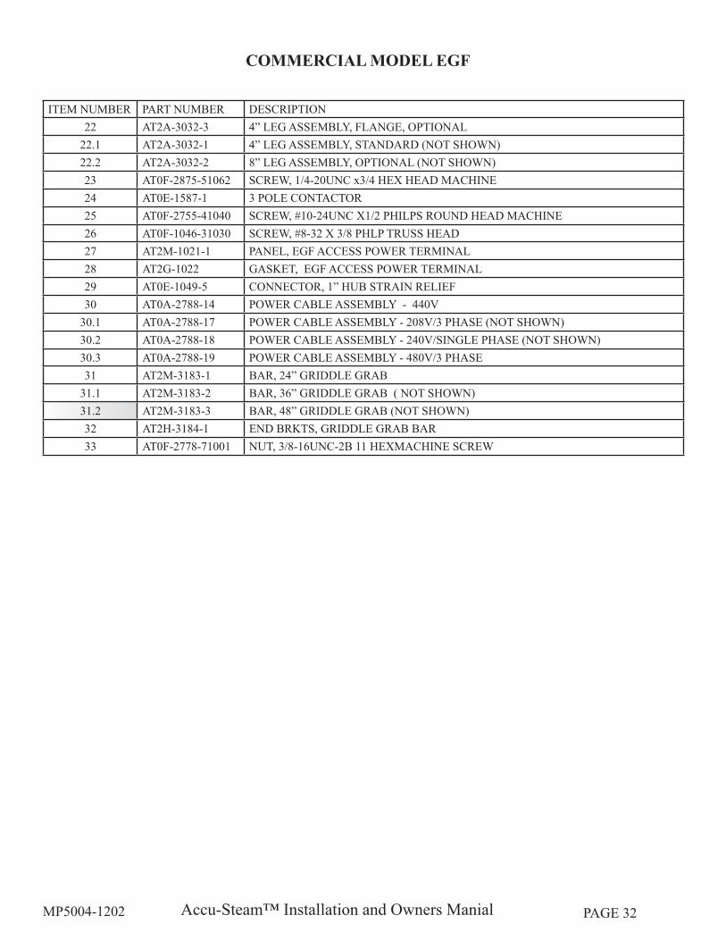
ITEM NUMBER PART NUMBER DESCRIPTION22 AT2A-3032-3 4” LEG ASSEMBLY, FLANGE, OPTIONAL
22.1 AT2A-3032-1 4” LEG ASSEMBLY, STANDARD (NOT SHOWN)22.2 AT2A-3032-2 8” LEG ASSEMBLY, OPTIONAL (NOT SHOWN)23 AT0F-2875-51062 SCREW, 1/4-20UNC x3/4 HEX HEAD MACHINE 24 AT0E-1587-1 3 POLE CONTACTOR25 AT0F-2755-41040 SCREW, #10-24UNC X1/2 PHILPS ROUND HEAD MACHINE26 AT0F-1046-31030 SCREW, #8-32 X 3/8 PHLP TRUSS HEAD27 AT2M-1021-1 PANEL, EGF ACCESS POWER TERMINAL28 AT2G-1022 GASKET, EGF ACCESS POWER TERMINAL29 AT0E-1049-5 CONNECTOR, 1” HUB STRAIN RELIEF30 AT0A-2788-14 POWER CABLE ASSEMBLY - 440V
30.1 AT0A-2788-17 POWER CABLE ASSEMBLY - 208V/3 PHASE (NOT SHOWN)30.2 AT0A-2788-18 POWER CABLE ASSEMBLY - 240V/SINGLE PHASE (NOT SHOWN)30.3 AT0A-2788-19 POWER CABLE ASSEMBLY - 480V/3 PHASE31 AT2M-3183-1 BAR, 24” GRIDDLE GRAB
31.1 AT2M-3183-2 BAR, 36” GRIDDLE GRAB ( NOT SHOWN)31.2 AT2M-3183-3 BAR, 48” GRIDDLE GRAB (NOT SHOWN)32 AT2H-3184-1 END BRKTS, GRIDDLE GRAB BAR33 AT0F-2778-71001 NUT, 3/8-16UNC-2B 11 HEXMACHINE SCREW
COMMERCIAL MODEL EGF
Accu-Steam™ Installation and Owners ManialMP5004-1202 PAGE 33
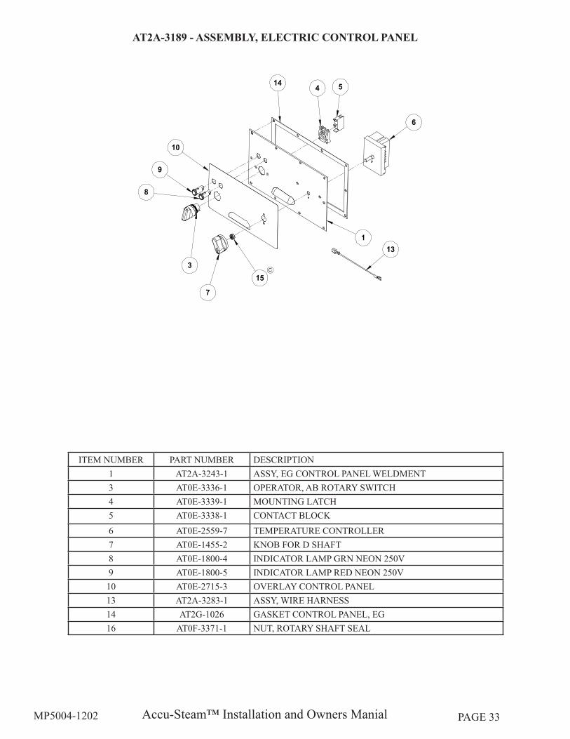
ITEM NUMBER PART NUMBER DESCRIPTION1 AT2A-3243-1 ASSY, EG CONTROL PANEL WELDMENT3 AT0E-3336-1 OPERATOR, AB ROTARY SWITCH4 AT0E-3339-1 MOUNTING LATCH5 AT0E-3338-1 CONTACT BLOCK6 AT0E-2559-7 TEMPERATURE CONTROLLER7 AT0E-1455-2 KNOB FOR D SHAFT8 AT0E-1800-4 INDICATOR LAMP GRN NEON 250V9 AT0E-1800-5 INDICATOR LAMP RED NEON 250V10 AT0E-2715-3 OVERLAY CONTROL PANEL13 AT2A-3283-1 ASSY, WIRE HARNESS14 AT2G-1026 GASKET CONTROL PANEL, EG16 AT0F-3371-1 NUT, ROTARY SHAFT SEAL
AT2A-3189 - ASSEMBLY, ELECTRIC CONTROL PANEL
Accu-Steam™ Installation and Owners ManialMP5004-1202 PAGE 34
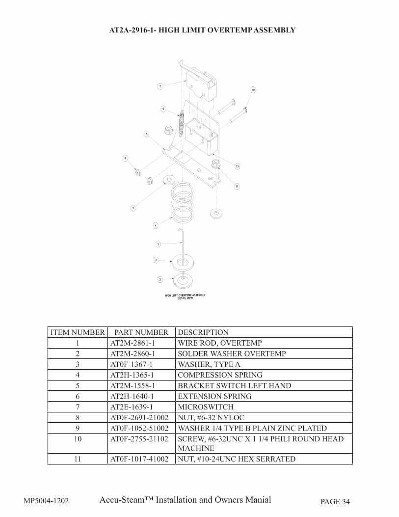
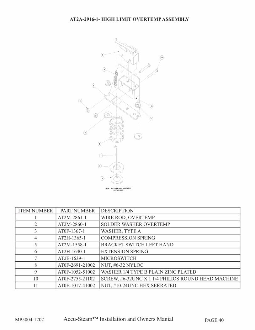
ITEM NUMBER PART NUMBER DESCRIPTION1 AT2M-2861-1 WIRE ROD, OVERTEMP2 AT2M-2860-1 SOLDER WASHER OVERTEMP3 AT0F-1367-1 WASHER, TYPE A4 AT2H-1365-1 COMPRESSION SPRING5 AT2M-1558-1 BRACKET SWITCH LEFT HAND6 AT2H-1640-1 EXTENSION SPRING7 AT2E-1639-1 MICROSWITCH8 AT0F-2691-21002 NUT, #6-32 NYLOC9 AT0F-1052-51002 WASHER 1/4 TYPE B PLAIN ZINC PLATED10 AT0F-2755-21102 SCREW, #6-32UNC X 1 1/4 PHILI ROUND HEAD
MACHINE11 AT0F-1017-41002 NUT, #10-24UNC HEX SERRATED
AT2A-2916-1- HIGH LIMIT OVERTEMP ASSEMBLY
Accu-Steam™ Installation and Owners ManialMP5004-1202 PAGE 35
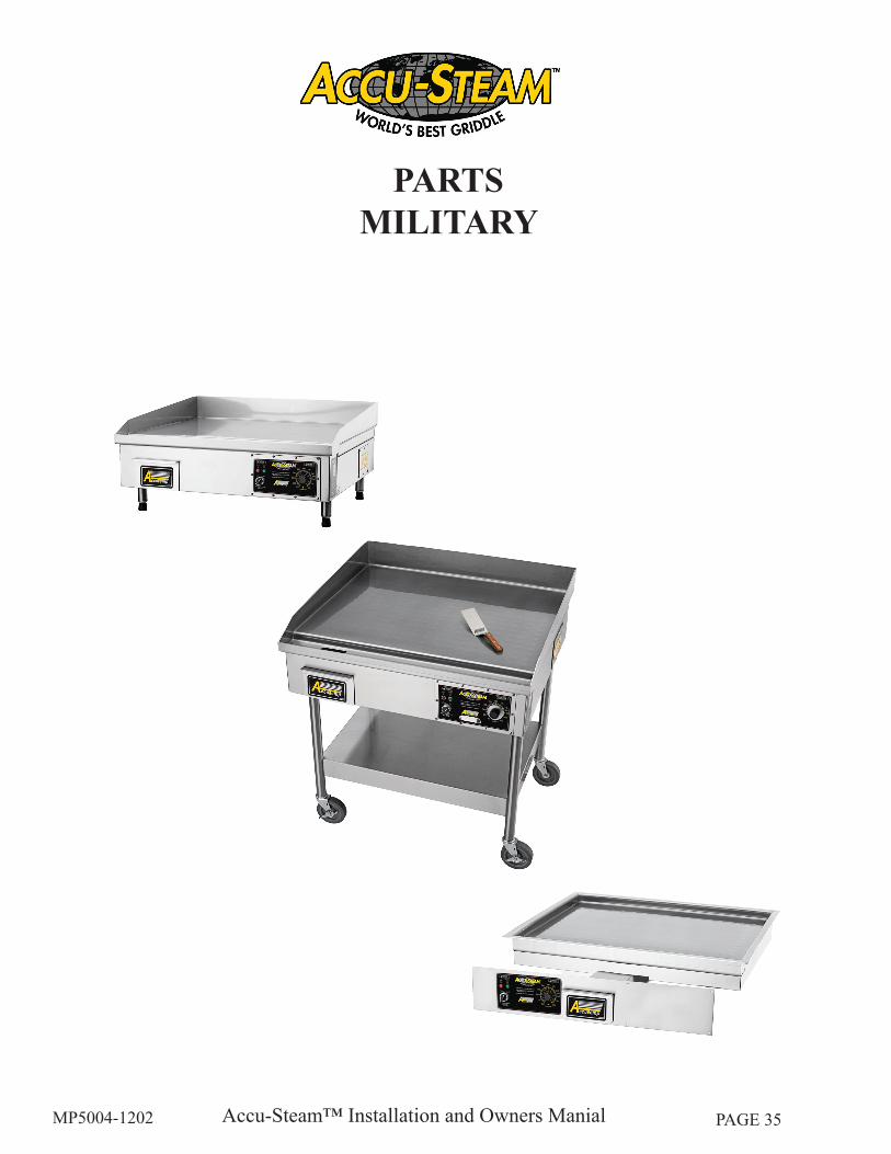
PARTSMILITARY
Accu-Steam™ Installation and Owners ManialMP5004-1202 PAGE 36
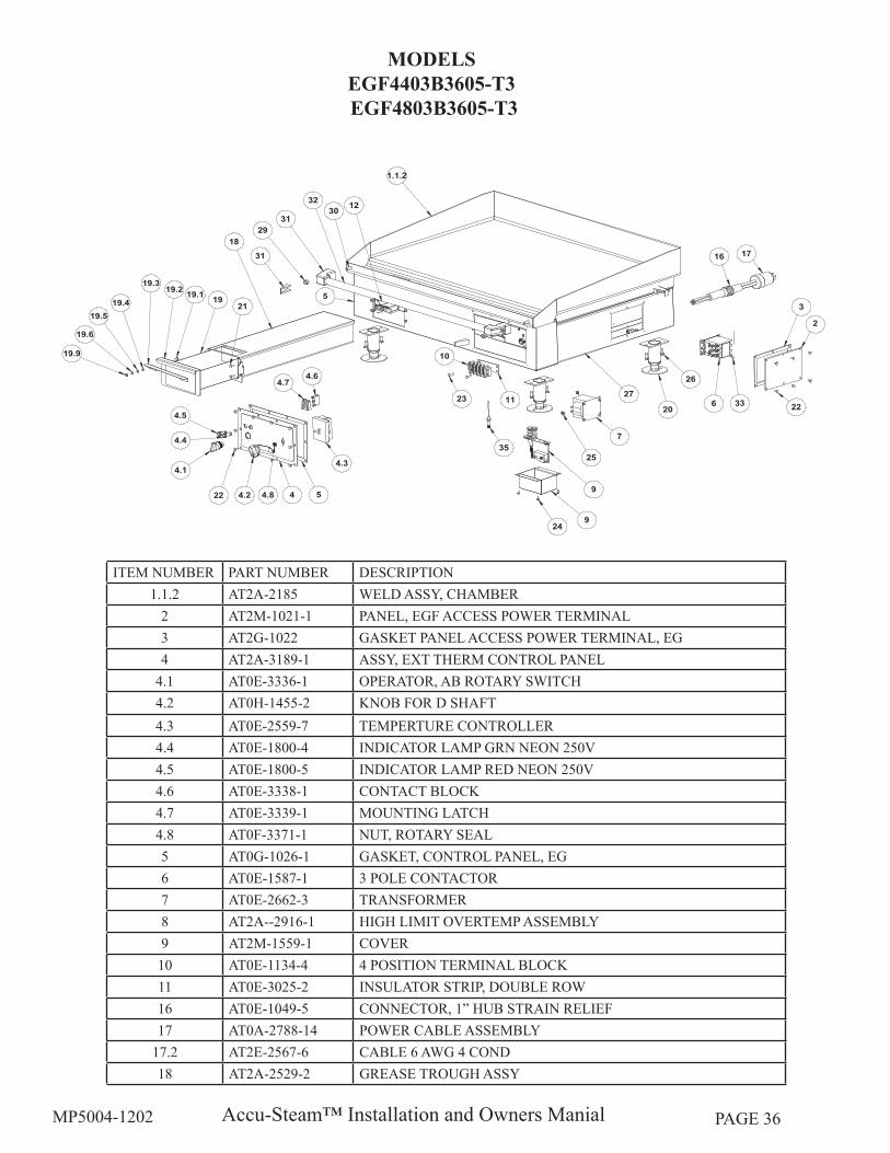
ITEM NUMBER PART NUMBER DESCRIPTION1.1.2 AT2A-2185 WELD ASSY, CHAMBER
2 AT2M-1021-1 PANEL, EGF ACCESS POWER TERMINAL3 AT2G-1022 GASKET PANEL ACCESS POWER TERMINAL, EG4 AT2A-3189-1 ASSY, EXT THERM CONTROL PANEL
4.1 AT0E-3336-1 OPERATOR, AB ROTARY SWITCH4.2 AT0H-1455-2 KNOB FOR D SHAFT4.3 AT0E-2559-7 TEMPERTURE CONTROLLER4.4 AT0E-1800-4 INDICATOR LAMP GRN NEON 250V4.5 AT0E-1800-5 INDICATOR LAMP RED NEON 250V4.6 AT0E-3338-1 CONTACT BLOCK4.7 AT0E-3339-1 MOUNTING LATCH4.8 AT0F-3371-1 NUT, ROTARY SEAL5 AT0G-1026-1 GASKET, CONTROL PANEL, EG6 AT0E-1587-1 3 POLE CONTACTOR7 AT0E-2662-3 TRANSFORMER8 AT2A--2916-1 HIGH LIMIT OVERTEMP ASSEMBLY9 AT2M-1559-1 COVER10 AT0E-1134-4 4 POSITION TERMINAL BLOCK11 AT0E-3025-2 INSULATOR STRIP, DOUBLE ROW16 AT0E-1049-5 CONNECTOR, 1” HUB STRAIN RELIEF17 AT0A-2788-14 POWER CABLE ASSEMBLY
17.2 AT2E-2567-6 CABLE 6 AWG 4 COND18 AT2A-2529-2 GREASE TROUGH ASSY
MODELS EGF4403B3605-T3 EGF4803B3605-T3
Accu-Steam™ Installation and Owners ManialMP5004-1202 PAGE 37
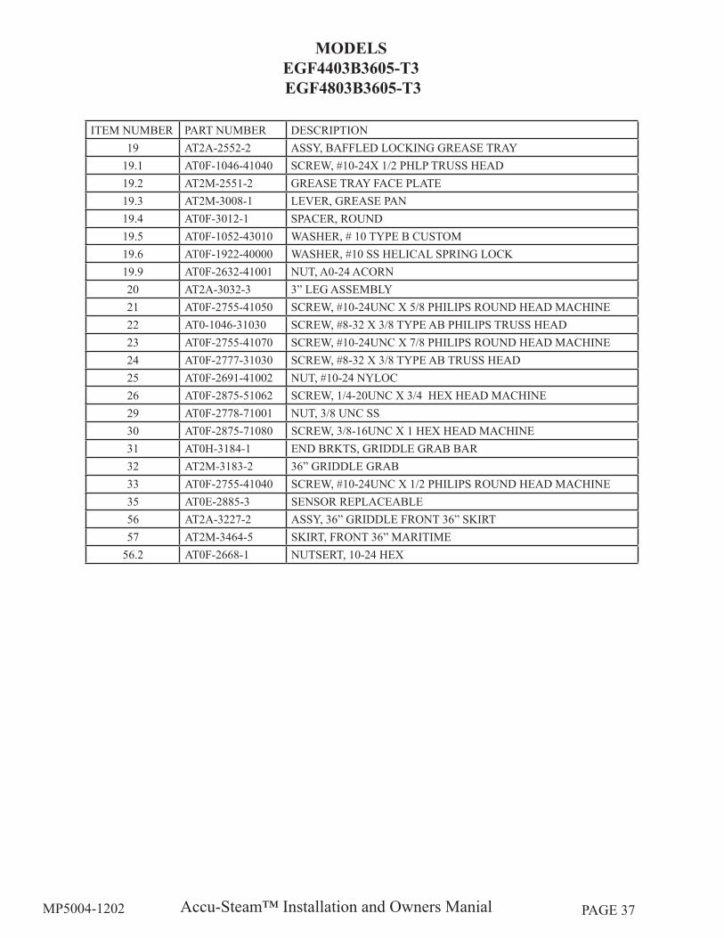
ITEM NUMBER PART NUMBER DESCRIPTION19 AT2A-2552-2 ASSY, BAFFLED LOCKING GREASE TRAY
19.1 AT0F-1046-41040 SCREW, #10-24X 1/2 PHLP TRUSS HEAD19.2 AT2M-2551-2 GREASE TRAY FACE PLATE19.3 AT2M-3008-1 LEVER, GREASE PAN19.4 AT0F-3012-1 SPACER, ROUND19.5 AT0F-1052-43010 WASHER, # 10 TYPE B CUSTOM19.6 AT0F-1922-40000 WASHER, #10 SS HELICAL SPRING LOCK19.9 AT0F-2632-41001 NUT, A0-24 ACORN20 AT2A-3032-3 3” LEG ASSEMBLY21 AT0F-2755-41050 SCREW, #10-24UNC X 5/8 PHILIPS ROUND HEAD MACHINE22 AT0-1046-31030 SCREW, #8-32 X 3/8 TYPE AB PHILIPS TRUSS HEAD23 AT0F-2755-41070 SCREW, #10-24UNC X 7/8 PHILIPS ROUND HEAD MACHINE24 AT0F-2777-31030 SCREW, #8-32 X 3/8 TYPE AB TRUSS HEAD25 AT0F-2691-41002 NUT, #10-24 NYLOC26 AT0F-2875-51062 SCREW, 1/4-20UNC X 3/4 HEX HEAD MACHINE29 AT0F-2778-71001 NUT, 3/8 UNC SS30 AT0F-2875-71080 SCREW, 3/8-16UNC X 1 HEX HEAD MACHINE 31 AT0H-3184-1 END BRKTS, GRIDDLE GRAB BAR32 AT2M-3183-2 36” GRIDDLE GRAB33 AT0F-2755-41040 SCREW, #10-24UNC X 1/2 PHILIPS ROUND HEAD MACHINE35 AT0E-2885-3 SENSOR REPLACEABLE56 AT2A-3227-2 ASSY, 36” GRIDDLE FRONT 36” SKIRT57 AT2M-3464-5 SKIRT, FRONT 36” MARITIME
56.2 AT0F-2668-1 NUTSERT, 10-24 HEX
MODELS EGF4403B3605-T3 EGF4803B3605-T3
Accu-Steam™ Installation and Owners ManialMP5004-1202 PAGE 38
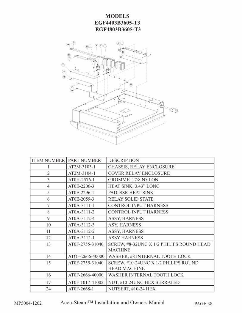
ITEM NUMBER PART NUMBER DESCRIPTION1 AT2M-3103-1 CHASSIS, RELAY ENCLOSURE2 AT2M-3104-1 COVER RELAY ENCLOSURE3 AT0H-2576-1 GROMMET, 7/8 NYLON4 AT0E-2206-3 HEAT SINK, 3.43” LONG5 AT0E-2296-1 PAD, SSR HEAT SINK6 AT0E-2059-3 RELAY SOLID STATE7 AT0A-3111-1 CONTROL INPUT HARNESS8 AT0A-3111-2 CONTROL INPUT HARNESS9 AT0A-3112-4 ASSY, HARNESS10 AT0A-3112-3 ASY, HARNESS11 AT0A-3112-2 ASSY, HARNESS12 AT0A-3112-1 ASSY HARNESS13 AT0F-2755-31040 SCREW, #8-32UNC X 1/2 PHILIPS ROUND HEAD
MACHINE14 ATOF-2666-40000 WASHER, #8 INTERNAL TOOTH LOCK15 AT0F-2755-31040 SCREW, #10-24UNC X 1/2 PHILIPS ROUND
HEAD MACHINE16 AT0F-2666-40000 WASHER INTERNAL TOOTH LOCK17 AT0F-1017-41002 NUT, #10-24UNC HEX SERRATED24 AT0F-2668-1 NUTSERT, #10-24 HEX
MODELS EGF4403B3605-T3 EGF4803B3605-T3
Accu-Steam™ Installation and Owners ManialMP5004-1202 PAGE 39
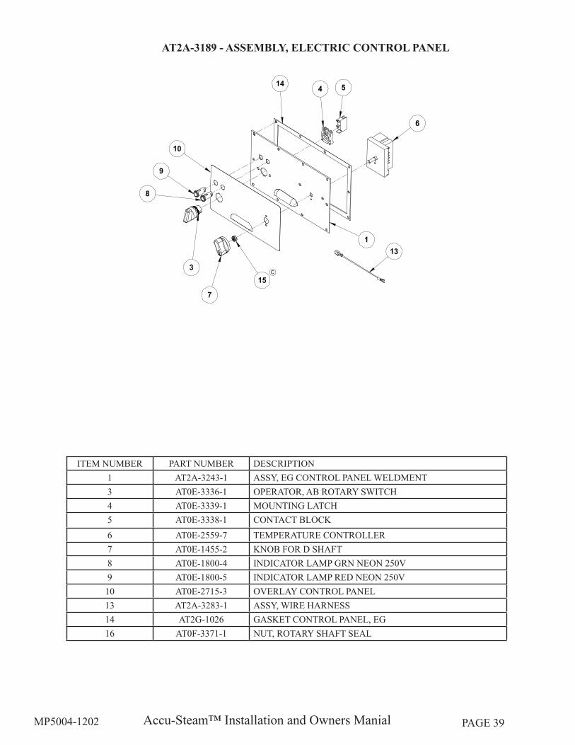
ITEM NUMBER PART NUMBER DESCRIPTION1 AT2A-3243-1 ASSY, EG CONTROL PANEL WELDMENT3 AT0E-3336-1 OPERATOR, AB ROTARY SWITCH4 AT0E-3339-1 MOUNTING LATCH5 AT0E-3338-1 CONTACT BLOCK6 AT0E-2559-7 TEMPERATURE CONTROLLER7 AT0E-1455-2 KNOB FOR D SHAFT8 AT0E-1800-4 INDICATOR LAMP GRN NEON 250V9 AT0E-1800-5 INDICATOR LAMP RED NEON 250V10 AT0E-2715-3 OVERLAY CONTROL PANEL13 AT2A-3283-1 ASSY, WIRE HARNESS14 AT2G-1026 GASKET CONTROL PANEL, EG16 AT0F-3371-1 NUT, ROTARY SHAFT SEAL
AT2A-3189 - ASSEMBLY, ELECTRIC CONTROL PANEL
Accu-Steam™ Installation and Owners ManialMP5004-1202 PAGE 40
ITEM NUMBER PART NUMBER DESCRIPTION1 AT2M-2861-1 WIRE ROD, OVERTEMP2 AT2M-2860-1 SOLDER WASHER OVERTEMP3 AT0F-1367-1 WASHER, TYPE A4 AT2H-1365-1 COMPRESSION SPRING5 AT2M-1558-1 BRACKET SWITCH LEFT HAND6 AT2H-1640-1 EXTENSION SPRING7 AT2E-1639-1 MICROSWITCH8 AT0F-2691-21002 NUT, #6-32 NYLOC9 AT0F-1052-51002 WASHER 1/4 TYPE B PLAIN ZINC PLATED10 AT0F-2755-21102 SCREW, #6-32UNC X 1 1/4 PHILIOS ROUND HEAD MACHINE11 AT0F-1017-41002 NUT, #10-24UNC HEX SERRATED
AT2A-2916-1- HIGH LIMIT OVERTEMP ASSEMBLY

Accu-Steam™ Installation and Owners ManialMP5004-1202 PAGE 41
ACCUSTEAM ELECTRIC SERIES SCHEMATICSMODEL EGF
Accu-Steam™ Installation and Owners ManialMP5004-1202 PAGE 42
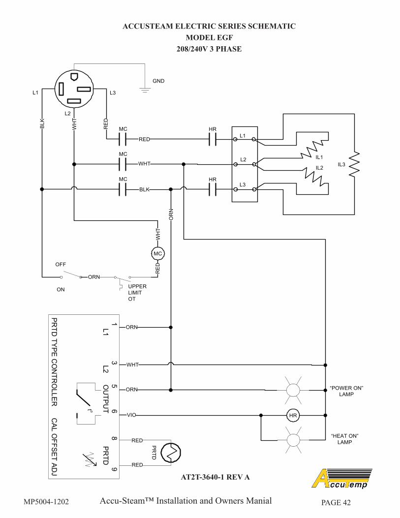
ACCUSTEAM ELECTRIC SERIES SCHEMATICMODEL EGF
208/240V 3 PHASE
AT2T-3640-1 REV A
Accu-Steam™ Installation and Owners ManialMP5004-1202 PAGE 43
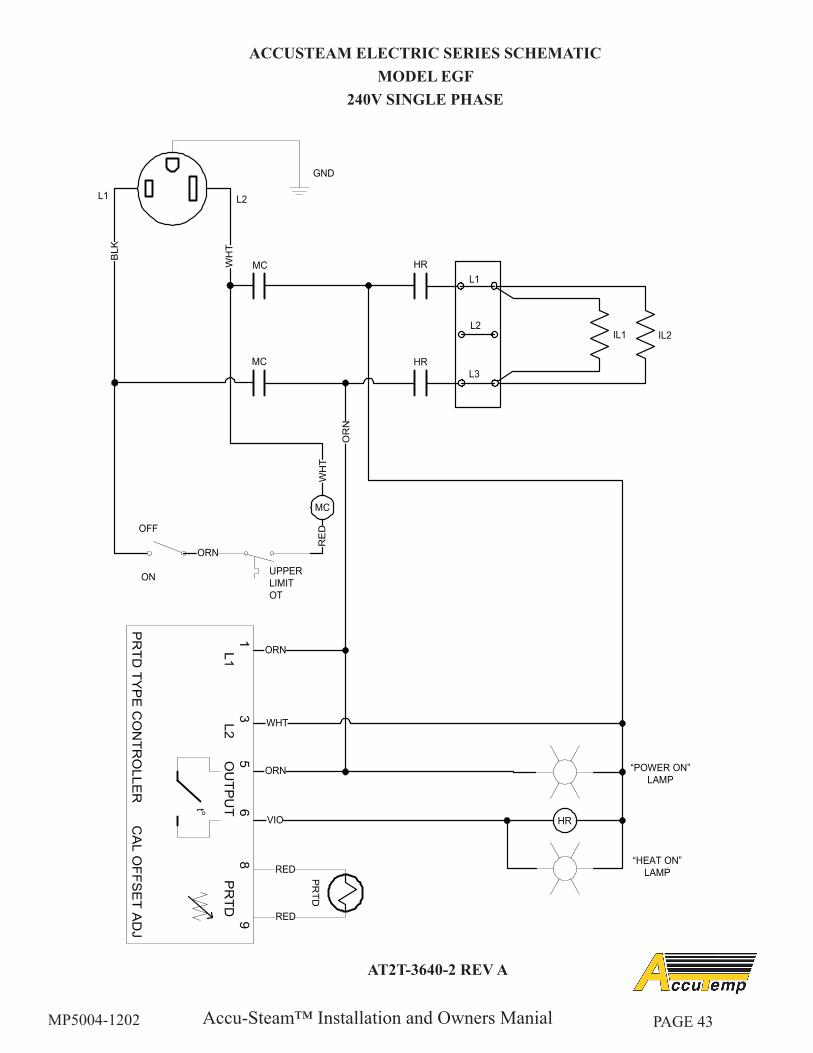
ACCUSTEAM ELECTRIC SERIES SCHEMATICMODEL EGF
240V SINGLE PHASE
AT2T-3640-2 REV A
Accu-Steam™ Installation and Owners ManialMP5004-1202 PAGE 44
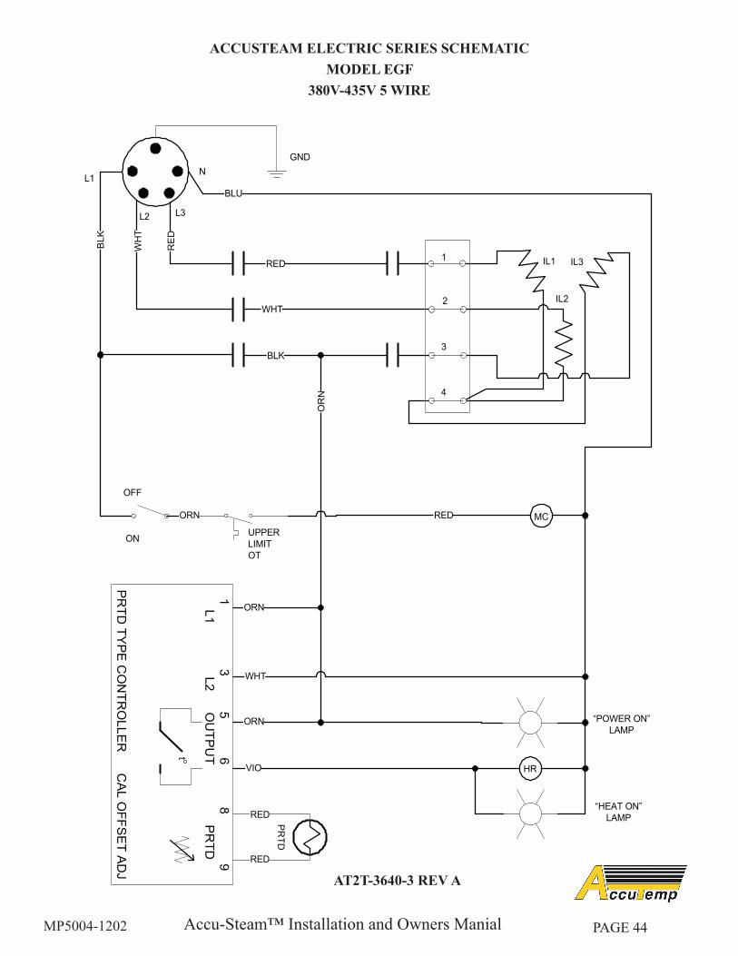
ACCUSTEAM ELECTRIC SERIES SCHEMATICMODEL EGF
380V-435V 5 WIRE
AT2T-3640-3 REV A
Accu-Steam™ Installation and Owners ManialMP5004-1202 PAGE 45
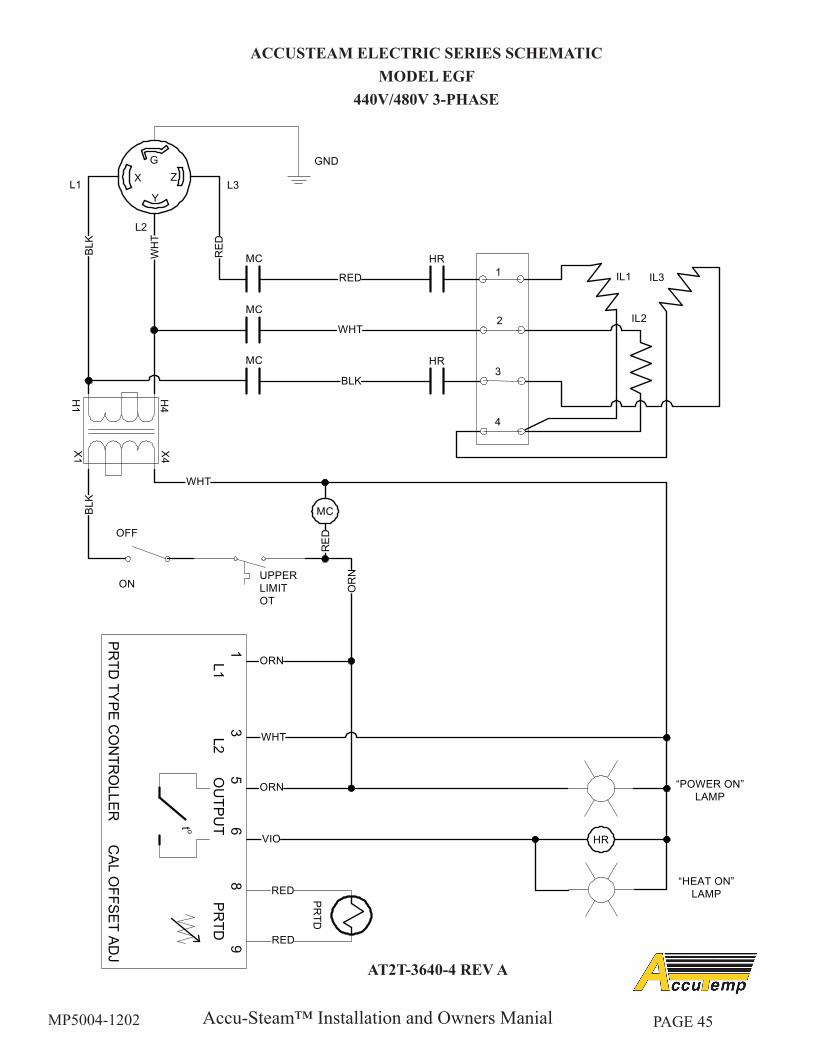
ACCUSTEAM ELECTRIC SERIES SCHEMATICMODEL EGF
440V/480V 3-PHASE
AT2T-3640-4 REV A

Accu-Steam™ Installation and Owners ManialMP5004-1202 PAGE 46
ACCUSTEAM ELECTRIC SERIES SCHEMATICSMODEL EGD
Accu-Steam™ Installation and Owners ManialMP5004-1202 PAGE 47
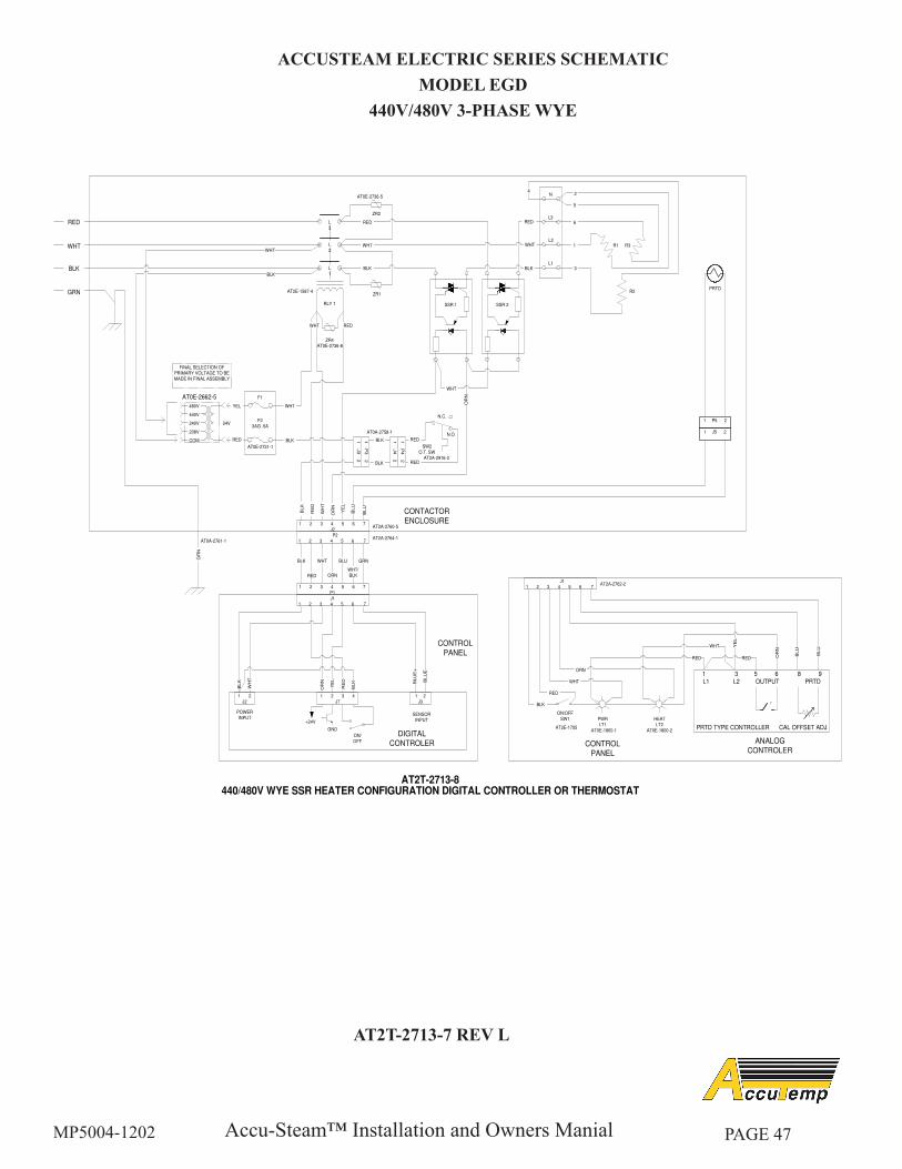
ACCUSTEAM ELECTRIC SERIES SCHEMATICMODEL EGD
440V/480V 3-PHASE WYE
AT2T-2713-7 REV L
AT2T-2713-8440/480V WYE SSR HEATER CONFIGURATION DIGITAL CONTROLLER OR THERMOSTAT
OR
N
YE
L
RED
WHT
BLK
GRN
WHT
WHT
BLK
BLU
BLU
BLK
FINAL SELECTION OF PRIMARY VOLTAGE TO BE MADE IN FINAL ASSEMBLY
480V
440V
240V
208V
COM
AT0E-2662-5
24V
F1
F23AG .5A
AT0E-2731-1
BLK
WHT
RED
ZR2
WHT
RED
BLK
ZR1
RED
AT2E-1587-4
AT0E-2736-5
AT0E-2736-8
RLY 1
ZR4
L3
L2
L1
WHT
SSR 1 SSR 2
1 P
3 2
1 J
3 2
SW2
O.T. SW
N.O.
N.C.
1 P
4 2
1 J
4 2
RED
RED
BLK
BLKAT2A-2916-2
AT0A-2758-1
1 P5 2
1 J5 2
WHT
1 2 3 4 5 6 7J2
1 2 3 4 5 6 7
P1
P21 2 3 4 5 6 7
WH
T
RE
D
OR
N
RED
BLK WHT
ORN
GRNBLU
WHT/BLK
J11 2 3 4 5 6 7
BL
K
WH
T
GR
N
BLU
E+
BL
UE
-
CONTROL
PANEL
BL
K
CONTACTOR
ENCLOSURE
AT2A-2764-1
AT2A-2760-5
AT0A-2761-1
YE
L
OR
N
RE
D
ON/OFF
BLK
1 2
J2
1 2 3 4
J7
1 2
J3
+24V
GND
SENSOR INPUT
POWER INPUT
YEL
RED
J11 2 3 4 5 6 7
ON/OFFSW1 PWR
LT1
HEAT
LT2
BLK
RED
WHT
ORN
YE
L
CONTROL
PANEL
AT2E-1755AT0E-1800-1 AT0E-1800-2
AT2A-2762-2
BLU
BLU
PRTD
RED RED
WHT
OR
N
DIGITAL
CONTROLER
1 3 5 6 8 9 L1 L2 OUTPUT PRTD
PRTD TYPE CONTROLLER CAL OFFSET ADJ
to
ANALOG
CONTROLER
BLK
WHT
RED
R1 R3
R2
5
1
6
3
L3
L1
L2
N4
2
Accu-Steam™ Installation and Owners ManialMP5004-1202 PAGE 48
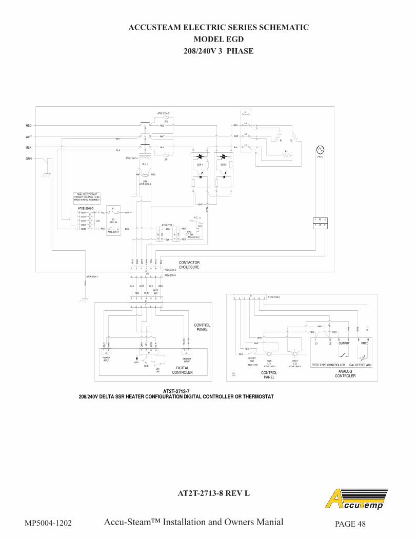
ACCUSTEAM ELECTRIC SERIES SCHEMATICMODEL EGD
208/240V 3 PHASE
AT2T-2713-8 REV L
AT2T-2713-7208/240V DELTA SSR HEATER CONFIGURATION DIGITAL CONTROLLER OR THERMOSTAT
L
OR
N
YE
L
RED
WHT
BLK
GRN
WHT
WHT
BLK
BLU
BLU
BLK
FINAL SELECTION OF PRIMARY VOLTAGE TO BE
MADE IN FINAL ASSEMBLY
480V
440V
240V
208V
COM
AT0E-2662-5
24V
F1
F23AG .5A
AT0E-2731-1
41
2
6
3
L3
L1
L2
5
BLK
WHT
RED
N
R1 R3
R2
ZR2
WHT
RED
BLK
ZR1
RED
AT2E-1587-4
AT0E-2736-5
AT0E-2736-8
RLY 1
ZR4
L3
L
2
L1
WHT
SSR 1 SSR 2
1 P
3 2
1 J
3 2
SW2O.T. SW
N.O.
N.C.
1 P
4 2
1 J
4 2
RED
RED
BLK
BLKAT2A-2916-2
AT0A-2758-1
1 P5 2
1 J5 2
WHT
1 2 3 4 5 6 7J2
1 2 3 4 5 6 7P1
P21 2 3 4 5 6 7
WH
T
RE
D
OR
N
RED
BLK WHT
ORN
GRNBLU
WHT/
BLK
J1
1 2 3 4 5 6 7
BL
K
WH
T
GR
N
BLU
E+
BL
UE
-
CONTROL
PANEL
BL
K
CONTACTOR
ENCLOSURE
AT2A-2764-1
AT2A-2760-5
AT0A-2761-1
YE
L
OR
N
RE
D
ON/
OFF
BLK
1 2J2
1 2 3 4J7
1 2J3
+24V
GND
SENSOR INPUT
POWER INPUT
YEL
RED
J11 2 3 4 5 6 7
ON/OFFSW1 PWR
LT1HEATLT2
BLK
RED
WHT
ORN
YE
L
CONTROL
PANEL
AT2E-1755AT0E-1800-1 AT0E-1800-2
AT2A-2762-2
BLU
BLU
PRTD
RED RED
WHT
OR
N
DIGITAL
CONTROLER
1 3 5 6 8 9 L1 L2 OUTPUT PRTD
PRTD TYPE CONTROLLER CAL OFFSET ADJ
to
ANALOG
CONTROLER
Accu-Steam™ Installation and Owners ManialMP5004-1202 PAGE 49
LIMITED WARRANTYOne Year - Parts & Labor - U.S. & Canada Only
AccuTemp Products, Inc. (AccuTemp) warrants that your AccuTemp equipment will be free of defects in material and workmanship under normal use for a period of twelve (12) months from installation or fifteen (15) months from date of shipment from AccuTemp, whichever date first occurs (the Warranty Period). Registration of AccuTemp equipment is required at the time of installation. Damage to AccuTemp equipment that occurs during shipment must be reported to the carrier, and is not covered under this warranty. The reporting of any damage during shipment is the sole responsibility of the commercial purchaser/user of such AccuTemp equipment.
AccuTemp provides an active service department, which should be contacted and advised of service issues, regardless of the warranty period. During the warranty period, AccuTemp agrees to repair or replace, at its option, F.O.B. factory, any part which proves to be defective due to defects in material or workmanship, provided the equipment has not been altered in any way and has been properly installed, maintained, and operated in accordance with the instructions in the AccuTemp Owners Manual. During the warranty period, AccuTemp also agrees to pay for any factory authorized equipment service agency (within the continental United States and Canada) for reasonable labor required to repair or replace, at our option, F.O.B. factory, any part which proves to be defective due to defects in materials or workmanship, provided the service agency has received advance approval from AccuTemp factory service to perform the repair or replacement. This warranty includes travel time not to exceed two hours and mileage not to exceed 50 miles
fittings or external electrical connections, minor adjustments, maintenance, gaskets or cleaning. AccuTemp will not reimburse the expense of labor required to replace parts after the expiration of the warranty period.Proper installation is the responsibility of the dealer, owner-user, or installing contractor and is not covered by this warranty. Improper installation can affect your warranty. Installation is the responsibility of the Dealer, Owner/User or the Installation Contractor. See the Installation section of the Owners Manual. While AccuTemp products are built to comply with applicable standards for manufacturers, including Underwriters Laboratories (UL) and Underwriters Laboratories Sanitation requirements, it is the responsibility of the owner and the installer to comply with any applicable local codes that may exist.AccuTemp makes no other warranties or guarantees, whether expressed or implied, including any warranties of performance, merchantability, or fitness for any particular purpose. AccuTemp liability on any claim of any kind, including negligence, with respect to the goods and services covered hereunder, shall in no case exceed the price of the goods and services, or parts thereof, which gives rise to the claim. In no event shall AccuTemp be liable for special, incidental, or consequential damages, or damages in the nature of penalties.This constitutes the entire warranty, which supersedes and excludes all other warranties, whether written, oral, or implied.
WARRANTY
(100 miles round trip), but does not include post start-up assistance or training, tightening of loose