Embed Size (px)
Citation preview
1
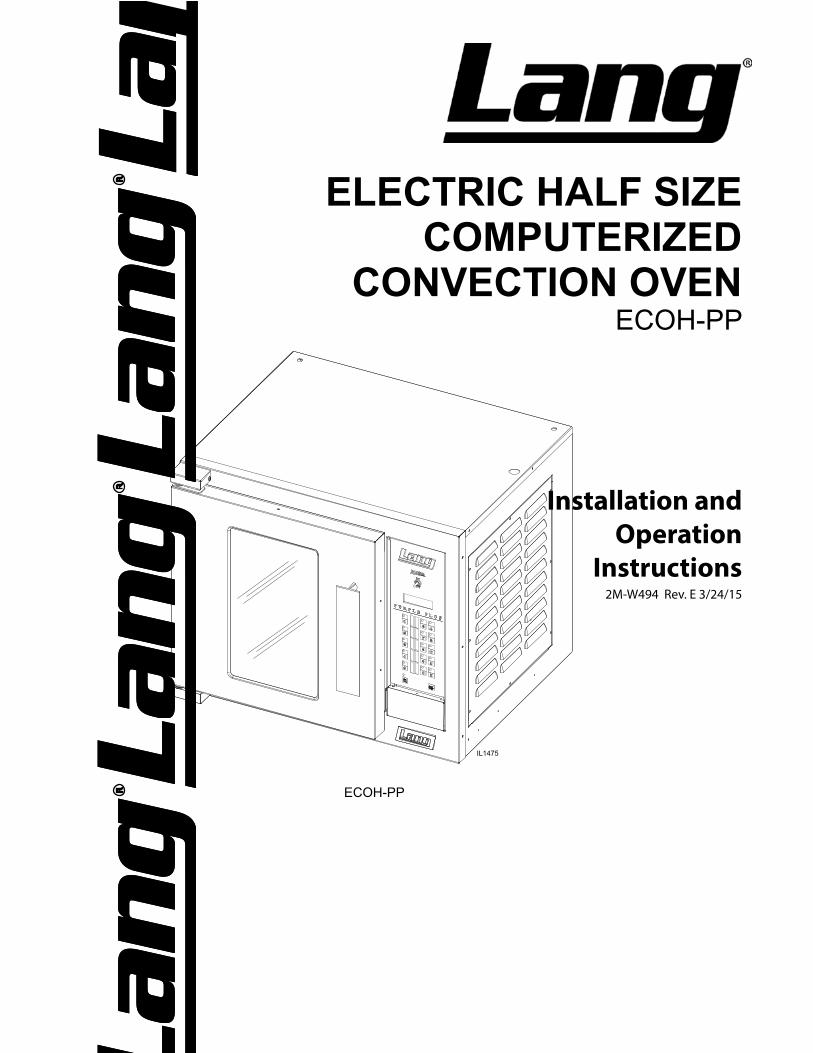
ELECTRIC HALF SIZE COMPUTERIZED
CONVECTION OVENECOH-PP
Installation and Operation
Instructions2M-W494 Rev. E 3/24/15
ECOH-PP
IL1475
2
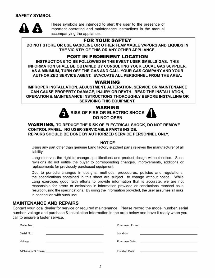
These symbols are intended to alert the user to the presence ofimportant operating and maintenance instructions in the manualaccompanying the appliance.
FOR YOUR SAFTEYDO NOT STORE OR USE GASOLINE OR OTHER FLAMMABLE VAPORS AND LIQUIDS IN
THE VICINTIY OF THIS OR ANY OTHER APPLIANCE.
POST IN PROMINENT LOCATIONINSTRUCTIONS TO BE FOLLOWED IN THE EVENT USER SMELLS GAS. THIS
INFORMATION SHALL BE OBTAINED BY CONSULTING YOUR LOCAL GAS SUPPLIER. AS A MINIMUM, TURN OFF THE GAS AND CALL YOUR GAS COMPANY AND YOUR AUTHORIZED SERVICE AGENT. EVACUATE ALL PERSONNEL FROM THE AREA.
WARNINGIMPROPER INSTALLATION, ADJUSTMENT, ALTERATION, SERVICE OR MAINTENANCE
CAN CAUSE PROPERTY DAMAGE, INJURY OR DEATH. READ THE INSTALLATION, OPERATION & MAINTENANCE INSTRUCTIONS THOROUGHLY BEFORE INSTALLING OR
SERVICING THIS EQUIPMENT. WARNING
RISK OF FIRE OR ELECTRIC SHOCKDO NOT OPEN
WARNING, TO REDUCE THE RISK OF ELECTRICAL SHOCK, DO NOT REMOVE CONTROL PANEL. NO USER-SERVICABLE PARTS INSIDE. REPAIRS SHOULD BE DONE BY AUTHORIZED SERVICE PERSONNEL ONLY.
NOTICEUsing any part other than genuine Lang factory supplied parts relieves the manufacturer of allliability.Lang reserves the right to change specifications and product design without notice. Such revisions do not entitle the buyer to corresponding changes, improvements, additions orreplacements for previously purchased equipment.Due to periodic changes in designs, methods, procedures, policies and regulations,the specifications contained in this sheet are subject to change without notice. While Lang exercises good faith efforts to provide information that is accurate, we are not responsible for errors or omissions in information provided or conclusions reached as aresult of using the specifications. By using the information provided, the user assumes all risks in connection with such use.
MAINTENANCE AND REPAIRSContact your local dealer for service or required maintenance. Please record the model number, serialnumber, voltage and purchase & Installation Information in the area below and have it ready when you call to ensure a faster service.
SAFETY SYMBOL
Model No.:
Serial No.:
Voltage:
1-Phase or 3 Phase:
Purchased From:
Location:
Purchase Date:
Installed Date:
3
TABLE OF CONTENTSSpecifications . . . . . . . . . . . . . . . . . . . . . . . . . . . . . 4Equipment Description . . . . . . . . . . . . . . . . . . . . . . . . 5Unpacking . . . . . . . . . . . . . . . . . . . . . . . . . . . . . . . 6Installation Leg Installation . . . . . . . . . . . . . . . . . . . . . . . . . . 7 Stacking the Oven . . . . . . . . . . . . . . . . . . . . . . . . . 7 Ventilation & Clearance . . . . . . . . . . . . . . . . . . . . . . 8 Electrical Connection . . . . . . . . . . . . . . . . . . . . . . . 8 Oven Voltage . . . . . . . . . . . . . . . . . . . . . . . . . . . 8Reversing the door . . . . . . . . . . . . . . . . . . . . . . . . . . 9Initial Start-Up Pre-Power On . . . . . . . . . . . . . . . . . . . . . . . . . . . 10 Power On . . . . . . . . . . . . . . . . . . . . . . . . . . . . . 10General Operation & Programming Control Panel . . . . . . . . . . . . . . . . . . . . . . . . . . . 11 Loading . . . . . . . . . . . . . . . . . . . . . . . . . . . . . . 12 Daily Operation . . . . . . . . . . . . . . . . . . . . . . . . . . 13 Program Menu Record Table . . . . . . . . . . . . . . . . . . . 14 Programming Procedures . . . . . . . . . . . . . . . . . . . . 15-16 Maintenance / Cleaning . . . . . . . . . . . . . . . . . . . . . . 17Troubleshooting Symptoms & Possible Causes . . . . . . . . . . . . . . . . . . 18Wiring Diagram ECOH-PP 208-240V WD61111-147 . . . . . . . . . . . . . . . . 19 ECOH-PP 220-380V, 240V-415V w 2SPD CE WD61111-170 . . 20 ECOH-PP 220-380V, 240-415V WD61111-151 . . . . . . . . . . 21 ECOH-PP 480V WD61111-168 . . . . . . . . . . . . . . . . . . 22Exploded View & Parts List . . . . . . . . . . . . . . . . . . . . . 24-34
PROBLEMS, QUESTIONS or CONCERNS
Before you proceed consult you authorized Lang service agent directoryor
Call the Lang Technical Service & Parts Department at 314-678-6315.
NOTICE ServiceonthisoranyotherLangappliancemustbeperformedbyqualifiedpersonnel only. Consult your Lang Authorized Service Agent Directory. You can call our tech service number 314-678-6315 or visit our website www.langworld.com for the service agent nearest you.
4
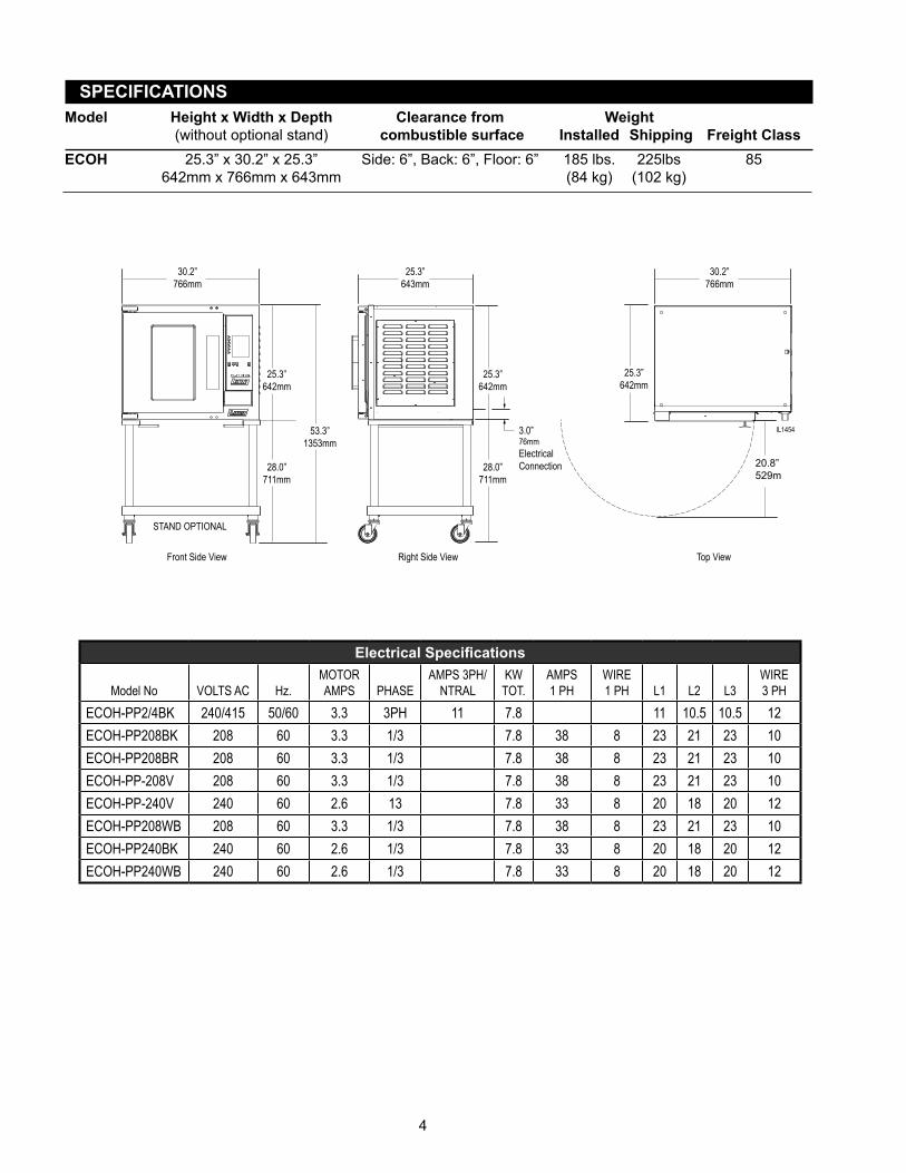
SPECIFICATIONSModel Height x Width x Depth Clearance from Weight (without optional stand) combustible surface Installed Shipping Freight ClassECOH 25.3” x 30.2” x 25.3” Side: 6”, Back: 6”, Floor: 6” 185 lbs. 225lbs 85 642mm x 766mm x 643mm (84 kg) (102 kg)
30.2”766mm
25.3”643mm
53.3”1353mm
25.3”642mm
25.3”642mm
20.8”529m
28.0”711mm
25.3”642mm
3.0”76mmElectrical Connection28.0”
711mm
30.2”766mm
STAND OPTIONAL
Front Side View Top ViewRight Side View
IL1454
ElectricalSpecifications
Model No VOLTS AC Hz.MOTOR AMPS PHASE
AMPS 3PH/NTRAL
KW TOT.
AMPS 1 PH
WIRE 1 PH L1 L2 L3
WIRE 3 PH
ECOH-PP2/4BK 240/415 50/60 3.3 3PH 11 7.8 11 10.5 10.5 12ECOH-PP208BK 208 60 3.3 1/3 7.8 38 8 23 21 23 10ECOH-PP208BR 208 60 3.3 1/3 7.8 38 8 23 21 23 10ECOH-PP-208V 208 60 3.3 1/3 7.8 38 8 23 21 23 10ECOH-PP-240V 240 60 2.6 13 7.8 33 8 20 18 20 12ECOH-PP208WB 208 60 3.3 1/3 7.8 38 8 23 21 23 10ECOH-PP240BK 240 60 2.6 1/3 7.8 33 8 20 18 20 12ECOH-PP240WB 240 60 2.6 1/3 7.8 33 8 20 18 20 12
5
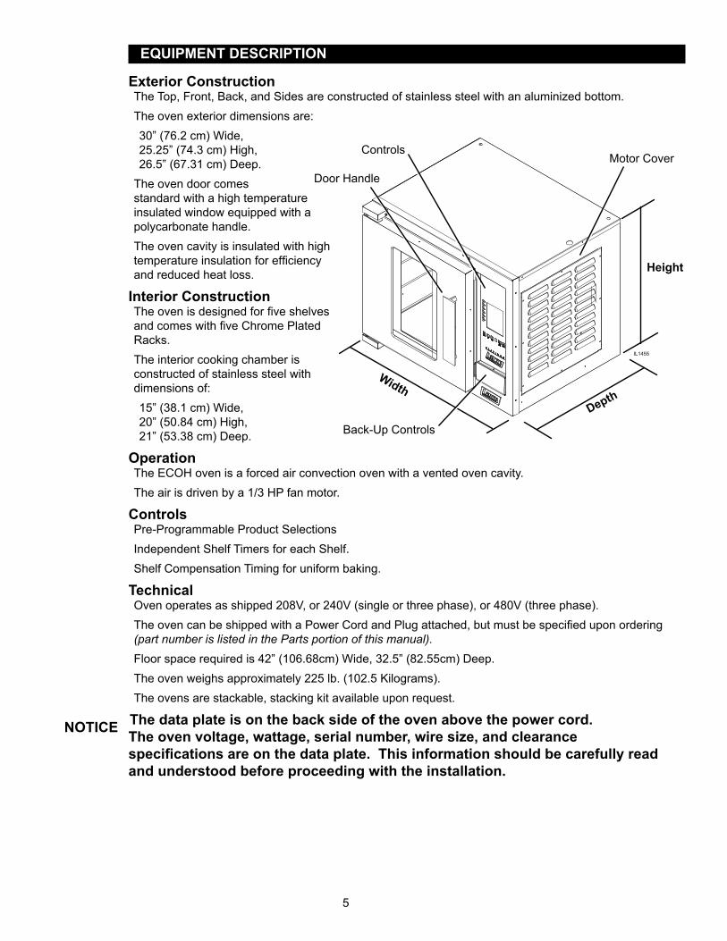
EQUIPMENT DESCRIPTION
Exterior ConstructionThe Top, Front, Back, and Sides are constructed of stainless steel with an aluminized bottom.The oven exterior dimensions are:30” (76.2 cm) Wide, 25.25” (74.3 cm) High, 26.5” (67.31 cm) Deep.
The oven door comes standard with a high temperature insulated window equipped with a polycarbonate handle.The oven cavity is insulated with high temperature insulation for efficiency and reduced heat loss.
Interior ConstructionThe oven is designed for five shelves and comes with five Chrome Plated Racks.The interior cooking chamber is constructed of stainless steel with dimensions of: 15” (38.1 cm) Wide, 20” (50.84 cm) High, 21” (53.38 cm) Deep.
OperationThe ECOH oven is a forced air convection oven with a vented oven cavity.The air is driven by a 1/3 HP fan motor.
ControlsPre-Programmable Product SelectionsIndependent Shelf Timers for each Shelf.Shelf Compensation Timing for uniform baking.
TechnicalOven operates as shipped 208V, or 240V (single or three phase), or 480V (three phase).The oven can be shipped with a Power Cord and Plug attached, but must be specified upon ordering (part number is listed in the Parts portion of this manual).Floor space required is 42” (106.68cm) Wide, 32.5” (82.55cm) Deep.The oven weighs approximately 225 lb. (102.5 Kilograms).The ovens are stackable, stacking kit available upon request.
The data plate is on the back side of the oven above the power cord. The oven voltage, wattage, serial number, wire size, and clearance specificationsareonthedataplate.Thisinformationshouldbecarefullyreadand understood before proceeding with the installation.
Depth
Width
Height
Motor Cover
Back-Up Controls
Controls
Door Handle
IL1455
NOTICE
6
UNPACKING
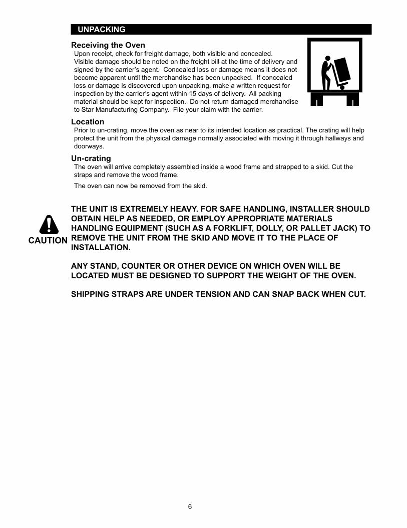
Receiving the OvenUpon receipt, check for freight damage, both visible and concealed. Visible damage should be noted on the freight bill at the time of delivery and signed by the carrier’s agent. Concealed loss or damage means it does not become apparent until the merchandise has been unpacked. If concealed loss or damage is discovered upon unpacking, make a written request for inspection by the carrier’s agent within 15 days of delivery. All packing material should be kept for inspection. Do not return damaged merchandise to Star Manufacturing Company. File your claim with the carrier.
LocationPrior to un-crating, move the oven as near to its intended location as practical. The crating will help protect the unit from the physical damage normally associated with moving it through hallways and doorways.
Un-cratingThe oven will arrive completely assembled inside a wood frame and strapped to a skid. Cut the straps and remove the wood frame. The oven can now be removed from the skid.
THE UNIT IS EXTREMELY HEAVY. FOR SAFE HANDLING, INSTALLER SHOULD OBTAIN HELP AS NEEDED, OR EMPLOY APPROPRIATE MATERIALS HANDLING EQUIPMENT (SUCH AS A FORKLIFT, DOLLY, OR PALLET JACK) TO REMOVE THE UNIT FROM THE SKID AND MOVE IT TO THE PLACE OF INSTALLATION.
ANY STAND, COUNTER OR OTHER DEVICE ON WHICH OVEN WILL BE LOCATED MUST BE DESIGNED TO SUPPORT THE WEIGHT OF THE OVEN.
SHIPPING STRAPS ARE UNDER TENSION AND CAN SNAP BACK WHEN CUT.
CAUTION

7
INSTALLATION
Leg Installation4” legs are available for single countertop installations. Single and double deck installations require 16” or 28” stand installation, casters may also be used in certain situations.To install the 4” legs, place some cardboard on the floor and gently tip the unit onto its back. Fasten the four, 4” legs into the threaded holes located on the bottom of the unit. Gently lift the oven into its operating position.16” & 28” stand installation, after following the assembly instructions that were provided with the stand, gently lower unit on to some cardboard as shown here. Align the stand with the bottom of the unit and secure with the hardware provided. With the assistance of carefully raise the unit to its vertical position.
Stacking the OvensTwo alignment pins (pn: 2C-20108-11) are needed if you intend on stacking two ECOH on each other as shown. These pins must be requested at the time of purchase, or call your Lang authorized service agent, or Lang parts department at 314-678-6315.Having completed the previous step remove any and all button plugs from the lower unit, so the upper unit will lay properly.Lay the upper unit on its back and screw the alignment pins into the two rear holes.With assistance lift the upper unit onto the lower unit, being certain that the alignment pins go into the alignment holes, as shown here.
NOTE: Each unit must have separate electrical connections
IL1430
16” or 28”Stand
4” Leg
Cardboard
Leg Mounting Hole
IL1431
Alignment Pinspn: 2C-20108-11
Alignment Hole
8
INSTALLATION continued
Ventilation and ClearancesStandard minimum clearance from combustible construction is as follows.
4” from side4” from back6” from floor
• These ovens may be set directly, without legs, on a curbed base or non-combustible floor.• If the oven is set without legs on a non-combustible floor or a curbed base, maintain a 4-inch back
clearance.• If the oven is set directly against a non-combustible back wall, maintain a 6-inch clearance to the floor.• Do not install the oven closer than 12 inches from an uncontrolled heat source (char broiler etc.) on
the right side.• Keep the area free & clear of combustible material, and do not obstruct the flow of combustion or
ventilation air.• The installation of any components such as a vent hood, grease extractors, and/or fire extinguisher
systems, must conform to the applicable nationally recognized installation standards.
NOTICE The installation of any components such as a vent hood, grease extractors,fireextinguishersystems,mustconformtotheir applicable National, State and locally recognized installation standards.
Electrical ConnectionThe electrical connection must be made in accordance with local codes or in the absence of local codes with NFPA No. 70 latest edition (in Canada use: CSA STD. C22.1).
The electrical service entrance is provided by a 1 1/4-inch knockout at the oven back directly behind the control compartment. A grounding lug is provided at the rear service entrance. Certain units are provided with or can be purchased with a Cord & Plug kit (Part number 9Q-ECOH-CK). This kit includes a 48” cord with a NEMA L15-30P plug and is for 3 Phase units ONLY. In stacked situations each units needs to have separate cord & plug assemblies.
Oven VoltageThe Lang Model ECOH ovens can be operated on 208, 240-volt (single or three phase), or 240/415V, 480-volt (three phase only) source. The Amp draw, KW rating, and phasing can be found in specification section of this manual or on the nameplate attached to the unit..
THIS APPLIANCE MUST BE GROUNDED AT THE TERMINAL PROVIDED. FAILURE TO GROUND THE APPLIANCE COULD RESULT IN ELECTROCUTION AND DEATH.
INSTALLATION OF THE UNIT MUST BE DONE BY PERSONNEL QUALIFIED TO WORK WITH ELECTRICITY AND PLUMBING. IMPROPER INSTALLATION CAN CAUSE INJURY TO PERSONNEL AND/OR DAMAGE TO EQUIPMENT. UNIT MUST BE INSTALLED IN ACCORDANCE WITH ALL APPLICABLE CODES.
WARNING
WARNING
9
8
4
1
5
6
8
8
10
11
1
125
4
7
7
6
8
8
8
8
9
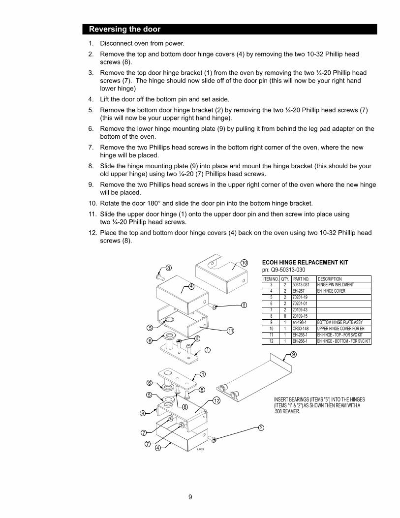
INSERT BEARINGS (ITEMS "5") INTO THE HINGES(ITEMS "1" & "2") AS SHOWN THEN REAM WITH A.508 REAMER.
ECOH HINGE RELPACEMENT KIT pn: Q9-50313-030ITEM NO. QTY. PART NO. DESCRIPTION
50313-031 HINGE PIN WELDMENTEH-267 EH HINGE COVER70201-1970201-0120109-4320109-15eh-198-1 BOTTOM HINGE PLATE ASSYCR30-148 UPPER HINGE COVER FOR EHEH-265-1 EH HINGE - TOP - FOR SVC KIT
3456789101112
2222281111 EH-266-1 EH HINGE - BOTTOM - FOR SVC KIT
IL1426
Reversing the door
1. Disconnect oven from power.2. Remove the top and bottom door hinge covers (4) by removing the two 10-32 Phillip head
screws (8).3. Remove the top door hinge bracket (1) from the oven by removing the two ¼-20 Phillip head
screws (7). The hinge should now slide off of the door pin (this will now be your right hand lower hinge)
4. Lift the door off the bottom pin and set aside.5. Remove the bottom door hinge bracket (2) by removing the two ¼-20 Phillip head screws (7)
(this will now be your upper right hand hinge).6. Remove the lower hinge mounting plate (9) by pulling it from behind the leg pad adapter on the
bottom of the oven.7. Remove the two Phillips head screws in the bottom right corner of the oven, where the new
hinge will be placed.8. Slide the hinge mounting plate (9) into place and mount the hinge bracket (this should be your
old upper hinge) using two ¼-20 (7) Phillips head screws.9. Remove the two Phillips head screws in the upper right corner of the oven where the new hinge
will be placed.10. Rotate the door 180° and slide the door pin into the bottom hinge bracket.11. Slide the upper door hinge (1) onto the upper door pin and then screw into place using
two ¼-20 Phillip head screws.12. Place the top and bottom door hinge covers (4) back on the oven using two 10-32 Phillip head
screws (8).
10
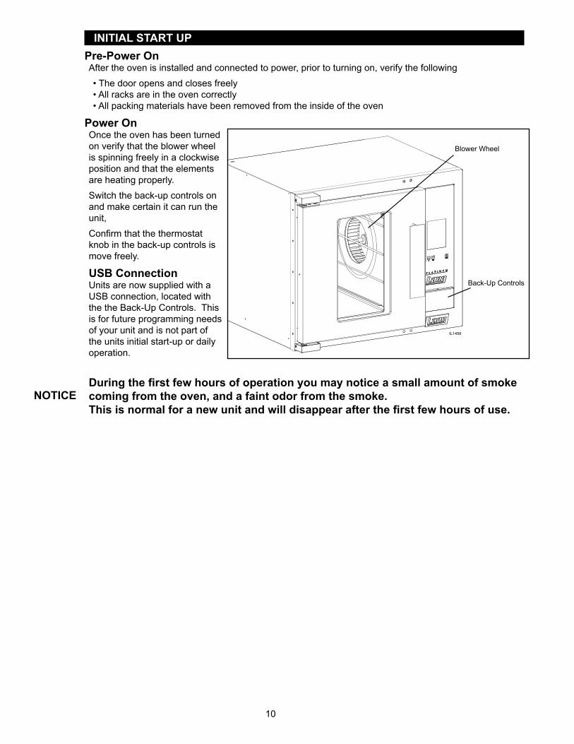
INITIAL START UPPre-Power OnAfter the oven is installed and connected to power, prior to turning on, verify the following• The door opens and closes freely• All racks are in the oven correctly• All packing materials have been removed from the inside of the oven
Power OnOnce the oven has been turned on verify that the blower wheel is spinning freely in a clockwise position and that the elements are heating properly.Switch the back-up controls on and make certain it can run the unit, Confirm that the thermostat knob in the back-up controls is move freely.
USB ConnectionUnits are now supplied with a USB connection, located with the the Back-Up Controls. This is for future programming needs of your unit and is not part of the units initial start-up or daily operation.
Duringthefirstfewhoursofoperationyoumaynoticeasmallamountofsmokecoming from the oven, and a faint odor from the smoke. Thisisnormalforanewunitandwilldisappearafterthefirstfewhoursofuse.
IL1456
Back-Up Controls
Blower Wheel
NOTICE
11
General Operation & Programming cont.ECOH-PP Control PanelThe control panel consists of the following items. Detailed operational descriptions are given later this section.Power Switch: Turns the oven on and offAlpha Numeric Display: Displays your interface with the computer.Product Select Button: Each button can be programmed for a specific menu, see programming section to see how.Shelf Select Button: Press to select which shelf the product will be placed on. “A” is the top position, “E” is the bottom position.Manual Program Button: Used when product being cooked is for one time only.Read / Clear Button: Used to read programs, clear programs, and to access program menus.
Typical Operation Sequence
Power Switch
AlphaNumeric Display
Product Select
Shelf Select
Manual Program
Read/ClearIL1458
Action Result
Turn power switch to ON.
Control panel comes on; display says “SELECT PRODUCT or READ/CLEAR TO PROGRAM.
Press a product button.
Display says “PRODUCT X PREHEATING TO XXX F”. Motor starts and oven begins preheating to the programmed temperature.
Beeper sounds briefly.Display says “READY SELECT PRODUCT TO START ”.
Open the oven doors and load the product. Close the door and press the product button again.
Beeper sounds briefly and display says, “SELECT OVEN SHELVES PRODUCT X”.
Press the shelf button(s) which correspond to the shelf positions, which the product is loaded (A equals the top shelf and E equals the bottom shelf).
Display shows a countdown timer and begins to count toward zero.
Beeper sounds continuously.
Display shows “DONE PRESS SHELF BUTTON X, REMOVE PRODUCT”, shelf button(s) flash.
Press the flashing shelf button(s).
Beeper stops. Display shows “READY SELECT PRODUCT TO START” if no other shelves carry product or resume count down for shelves that still have product cooking.
Open oven door and remove the product, which corresponds to flashing shelf button(s).
12
General Operation & Programming cont.
LoadingHere are some things to remember when loading your oven.• When loading and unloading the oven, stage products and racks so the oven door is opened for the least amount
of time.• Be sure that racks are level within the oven.• Bent or warped pans can greatly affect the evenness of the cook or bake.• If using baker’s parchment, be sure the parchment does not blow over the product. That will create an uneven
bake.• Load each shelf evenly. Spaces should be maintained equally between the pan and oven walls, front and back.• Do not overload pan’s this will create an uneven bake.• For best baking results, load the oven from the center out during random loading.
ALWAYS KEEP THE AREA NEAR THE APPLIANCE FREE FROM COMBUSTIBLE MATERIALS.
KEEP FLOOR IN FRONT OF EQUIPMENT CLEAN AND DRY. IF SPILLS OCCUR, CLEAN IMMEDIATELY, TO AVOID THE DANGER OF SLIPS OR FALLS.
CAUTION
13
Daily OperationStep 1: Turn the Power Switch on by switching the toggle switch to the up position.Step 2: Screen will appear as below.Select the product you wish to bake by pressing the number key (0-9) for that product.
Step 3: Screen will display:When the oven reaches the desired temperature, the screen will display:
Step 4: Open the oven door, place product in the oven. Close the oven door and press the program key you are using.
Step 5: The display will now read:Press the lettered keys indicating what shelves
you placed product on to bake (A is the top shelf).
SELECT PRODUCT ORREAD/CLEAR TO PROGRAMXX:XX PM XXX F
IL1459
PRODUCT 1PREHEATING TO XXX FXX:XX PM XXX F
IL1460
READYSELECT PRODUCT TO STARTXX:XX PM XXX F
IL1461
SELECT OVEN SHELVESPRODUCT 1XXXF XX:XX:XXXX:XX PM XXX F
IL1462
NO SHELF SELECTEDPRESS E TO CONTINUE
IL1463
If you do not select a shelf, the oven will beep and the following display will appear:
Press the E Key and the previous display will appear, again asking to select oven shelvesStep 6: Once a shelf or shelves have been selected, the display will now read:
At this time, you may select any other pre-set product program which has the same oven temperature. A lighted red light next to a numbered product key indicates that the program is compatible with the program selected, and can be run at the same time.Step 7: When the bake time is concluded, the oven will beep and the display will read:
Step 8: Once you have completed baking on one pre-set program, you may change to another pre-set program by pressing the Read/Clear Key.The display will now read:
COOKING PRODUCT XXTIER #1 XX:XX:XXSELECT PRODUCT XX:XX PM XXX F
IL1462
DONEPRESS SHELF BUTTONREMOVE PRODUCT XX:XX PM XXX F
IL1465
SELECT PRODUCT ORREAD/CLEAR TO PROGRAM
IL1466
DAILY OPERATION PURPLE PLUS CONVECTION OVENS
ECOH-PP, ECOF-PP, GCOF-PP, EHS-PP, ECCO-PP, GCCO-PP
14
PRO
GR
AM
MIN
G PU
RPLE PLU
S C
ON
VECTIO
N O
VENS
EC
OH
-PP, E
CO
F-PP, G
CO
F-PP,
EH
S-P
P, EC
CO
-PP, G
CC
O-P
P
Product
Nam
eTier 1
Tier 2Tier 3
Tier 4C
ooking Tem
pC
ooking Tim
eC
ooking C
urveFan
Speed
Pulse
Rate
Cooking Tem
pC
ooking Tim
eC
ooking C
urveFan
Speed
Pulse
Rate
Cooking Tem
pC
ooking Tim
eC
ooking C
urveFan
Speed
Pulse
Rate
Cooking Tem
pC
ooking Tim
eC
ooking C
urveFan
Speed
Pulse
Rate
ex: Biscuits
325°F12:30
50%H
I100%
Record Your M
enus Before Entering Your Program
.R
ecord your specific menu item
s using the table below, prior to entering them
into your units program
. Keep for your records.
15
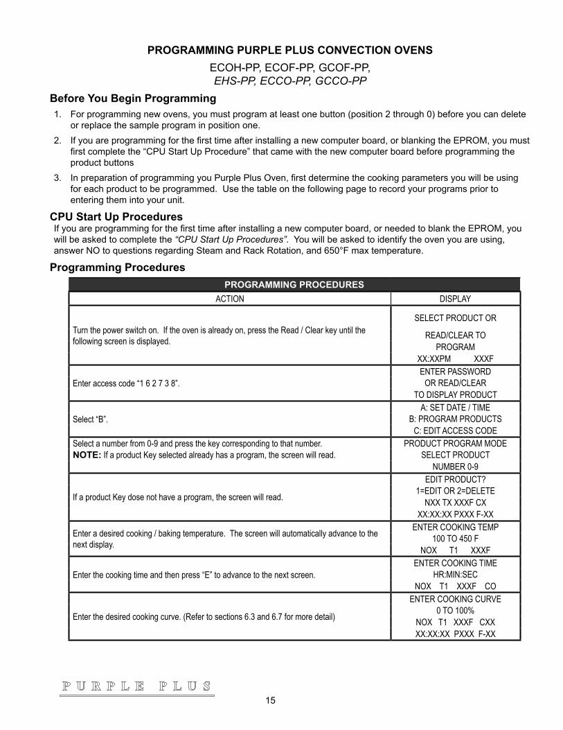
PROGRAMMING PURPLE PLUS CONVECTION OVENSECOH-PP, ECOF-PP, GCOF-PP, EHS-PP, ECCO-PP, GCCO-PP
Before You Begin Programming1. For programming new ovens, you must program at least one button (position 2 through 0) before you can delete
or replace the sample program in position one.2. If you are programming for the first time after installing a new computer board, or blanking the EPROM, you must
first complete the “CPU Start Up Procedure” that came with the new computer board before programming the product buttons
3. In preparation of programming you Purple Plus Oven, first determine the cooking parameters you will be using for each product to be programmed. Use the table on the following page to record your programs prior to entering them into your unit.
CPU Start Up ProceduresIf you are programming for the first time after installing a new computer board, or needed to blank the EPROM, you will be asked to complete the “CPU Start Up Procedures”. You will be asked to identify the oven you are using, answer NO to questions regarding Steam and Rack Rotation, and 650°F max temperature.
Programming ProceduresPROGRAMMING PROCEDURES
ACTION DISPLAY
Turn the power switch on. If the oven is already on, press the Read / Clear key until the following screen is displayed.
SELECT PRODUCT OR
READ/CLEAR TOPROGRAM
XX:XXPM XXXF
Enter access code “1 6 2 7 3 8”.ENTER PASSWORD
OR READ/CLEARTO DISPLAY PRODUCT
Select “B”.A: SET DATE / TIME
B: PROGRAM PRODUCTSC: EDIT ACCESS CODE
Select a number from 0-9 and press the key corresponding to that number. PRODUCT PROGRAM MODENOTE: If a product Key selected already has a program, the screen will read. SELECT PRODUCT
NUMBER 0-9
If a product Key dose not have a program, the screen will read.
EDIT PRODUCT?1=EDIT OR 2=DELETE
NXX TX XXXF CXXX:XX:XX PXXX F-XX
Enter a desired cooking / baking temperature. The screen will automatically advance to the next display.
ENTER COOKING TEMP100 TO 450 F
NOX T1 XXXF
Enter the cooking time and then press “E” to advance to the next screen.ENTER COOKING TIME
HR:MIN:SECNOX T1 XXXF CO
Enter the desired cooking curve. (Refer to sections 6.3 and 6.7 for more detail)
ENTER COOKING CURVE0 TO 100%
NOX T1 XXXF CXXXX:XX:XX PXXX F-XX
16
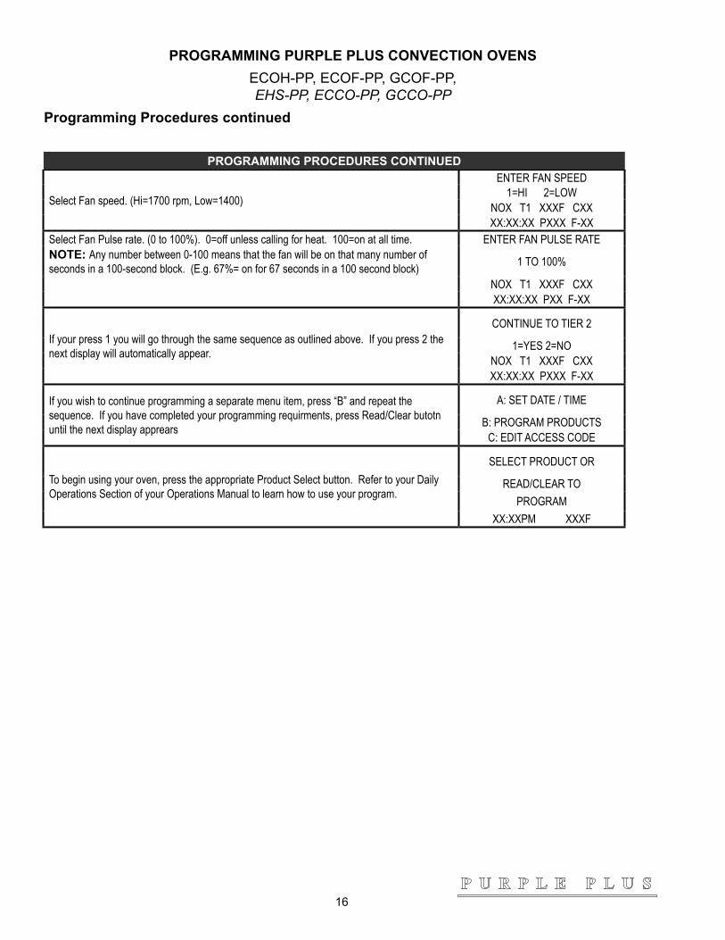
PROGRAMMING PURPLE PLUS CONVECTION OVENSECOH-PP, ECOF-PP, GCOF-PP, EHS-PP, ECCO-PP, GCCO-PP
Programming Procedures continued
PROGRAMMING PROCEDURES CONTINUED
Select Fan speed. (Hi=1700 rpm, Low=1400)
ENTER FAN SPEED 1=HI 2=LOW
NOX T1 XXXF CXXXX:XX:XX PXXX F-XX
Select Fan Pulse rate. (0 to 100%). 0=off unless calling for heat. 100=on at all time. ENTER FAN PULSE RATENOTE: Any number between 0-100 means that the fan will be on that many number of seconds in a 100-second block. (E.g. 67%= on for 67 seconds in a 100 second block) 1 TO 100%
NOX T1 XXXF CXXXX:XX:XX PXX F-XX
If your press 1 you will go through the same sequence as outlined above. If you press 2 the next display will automatically appear.
CONTINUE TO TIER 2
1=YES 2=NONOX T1 XXXF CXXXX:XX:XX PXXX F-XX
If you wish to continue programming a separate menu item, press “B” and repeat the sequence. If you have completed your programming requirments, press Read/Clear butotn until the next display apprears
A: SET DATE / TIME
B: PROGRAM PRODUCTSC: EDIT ACCESS CODE
To begin using your oven, press the appropriate Product Select button. Refer to your Daily Operations Section of your Operations Manual to learn how to use your program.
SELECT PRODUCT OR
READ/CLEAR TOPROGRAM
XX:XXPM XXXF
17
MAINTENANCE
• Oven interiors should be wiped down daily and thoroughly cleaned weekly using warm water and mild detergent. DO NOT use caustic cleaners.
• The appliance should be thoroughly checked at six-monthly intervals by a qualified technician (heating unit, mechanical stability, corrosion...) with particular emphasis on all control and safety devices.
CLEANING • Always start with a cold oven.• The stainless exterior can easily be cleaned using stainless steel cleaner.• Always follow the cleaner manufacturer’s instructions when using any cleaner.• Care should be taken to prevent caustic cleaning compounds from coming in contact with the fan wheel.• The oven racks, rack slides, may be cleaned outside the oven cavity using oven cleaner. • Using any harsh chemicals will result in the removal of the ETC coating and etching of the
porcelain below it. The oven interior should only be cleaned using a mild soap and a non metal scouring pad. DO NOT use caustic cleaners.
• Always apply stainless steel cleaners when the oven is cold and rub in the direction of the metal’s grain.
KEEP WATER AND SOLUTIONS OUT OF CONTROLS. NEVER SPRAY OR HOSE CONTROL CONSOLE, ELECTRICAL CONNECTIONS, ETC.
MOST CLEANERS ARE HARMFUL TO THE SKIN, EYES, MUCOUS MEMBRANES AND CLOTHING. PRECAUTIONS SHOULD BE TAKEN TO WEAR RUBBER GLOVES, GOGGLES OR FACE SHIELD AND PROTECTIVE CLOTHING.
CAREFULLY READ THE WARNING AND FOLLOW THE DIRECTIONS ON THE LABEL OF THE CLEANER TO BE USED.
NEVER LEAVE A CHLORINE SANITIZER IN CONTACT WITH STAINLESS STEEL SURFACES LONGER THAN 10 MINUTES. LONGER CONTACT CAN CAUSE CORROSION.
WARNING
CAUTION
18
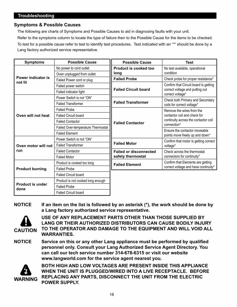
Troubleshooting
Symptoms & Possible CausesThe following are charts of Symptoms and Possible Causes to aid in diagnosing faults with your unit.Refer to the symptoms column to locate the type of failure then to the Possible Cause for the items to be checked.To test for a possible cause refer to test to identify test procedures. Test indicated with an “*” should be done by a Lang factory authorized service representative.
Possible Cause TestProduct is cooked too long
No test available, operational condition
Failed Probe Check probe for proper resistance*
Failed Circuit boardConfirm that Circuit board is getting correct voltage and putting out correct voltage*
Failed Transformer Check both Primary and Secondary coils for correct voltage*
Failed Contactor
Remove the wires from the contactor coil and check for continuity across the contactor coil connection*Ensure the contactor moveable points move freely up and down*
Failed Motor Confirm that motor is getting correct voltage*
Failed or disconnected safety thermostat
Check across the thermostat connectors for continuity*
Failed Element Confirm that Elements are getting correct voltage and have continuity*
NOTICE If an item on the list is followed by an asterisk (*), the work should be done by a Lang factory authorized service representative.
USE OF ANY REPLACEMENT PARTS OTHER THAN THOSE SUPPLIED BY LANG OR THEIR AUTHORIZED DISTRIBUTORS CAN CAUSE BODILY INJURY TO THE OPERATOR AND DAMAGE TO THE EQUIPMENT AND WILL VOID ALL WARRANTIES.
NOTICE ServiceonthisoranyotherLangappliancemustbeperformedbyqualifiedpersonnel only. Consult your Lang Authorized Service Agent Directory. You can call our tech service number 314-678-6315 or visit our website www.langworld.com for the service agent nearest you.
BOTH HIGH AND LOW VOLTAGES ARE PRESENT INSIDE THIS APPLIANCE WHEN THE UNIT IS PLUGGED/WIRED INTO A LIVE RECEPTACLE. BEFORE REPLACING ANY PARTS, DISCONNECT THE UNIT FROM THE ELECTRIC POWER SUPPLY.
CAUTION
WARNING
Symptoms Possible Cause
Power indicator is not lit
No power to cord outletOven unplugged from outletFailed Power cord or plugFailed power switchFailed indicator light
Oven will not heat
Power Switch is not “ON”Failed TransformerFailed ProbeFailed Circuit boardFailed ContactorFailed Over-temperature ThermostatFailed Element
Oven motor will not run
Power Switch is not “ON”Failed TransformerFailed ContactorFailed Motor
Product burningProduct is cooked too longFailed ProbeFailed Circuit board
Product is under done
Product is not cooked long enoughFailed ProbeFailed Circuit board
19
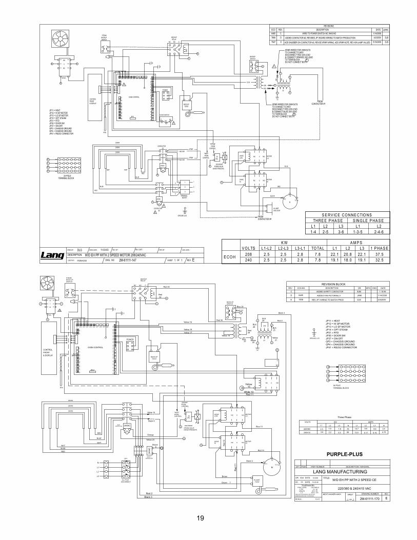
C
D
D
B
JP41
POWER
XFMR WIRED FOR 208VOLTSTO CHANGE TO 240VDISCONNECT RED 208 LEAD& CONNECT BLUE 240 LEADTO TERM BLOCKDO NOT CONNECT BOTH
240
208 B
CONTROLFRONT& DISPLAY
OVEN CONTROL
STEAMBACKUPSWITCH
C
A
240V
CNO
RTD
BACKUPSWITCH
BACKUPTSTAT
BACKUPRELAY
NC
12/24
24
240
A
C
DOOR SWITCH
C NCNO
GROUND LUG
D
B A
24 POLETERMINAL BLOCK
B
24VACC
D
LE
208
XFMR WIRED FOR 208VOLTSTO CHANGE TO 240VDISCONNECT RED 208 LEAD& CONNECT ORANGE 240 LEADTO TERM BLOCKDO NOT CONNECT BOTH
A
E
11-03-03
D
B
D
FROMCONTACTOR #1
24VAC
"STEAM"FROM
CONTROL
SOLENOIDSTEAM VALVE
(WHEN PRESENT)
6
32
54
1
2500W
2500W
BLACK
RED
BLUE
2500W
FROMCONTACTOR #1
MOTORLO
MOTORHI
24VACHI
24VACLOW
CNC NO
NOCNC
MOTOR
XFMR
M
TERMINALBLOCK
HI-LIMITDISC-STAT
24VAC
CONTACTOR#1
MOTOR
XFMR
1
2
33
2
1
L
D
"HEAT"FROM
CONTROL
P1
T9
T7-T4
RED
BLUE
WHTWHT
BLUE
RED
DC
AB
CONTACTOR#2
JP8
JP9
JP6
JP5
JP7
JP33
JP31
JP32
JP34
JP30
JP40
JP35
JP36
JP37
JP38
JP39
2726
JP21
JP22
JP23
JP24
JP3
JP4
JP1
JP2
JP20JP19JP18JP17JP16JP15JP14JP13JP12JP11
JP11 = HEATJP12 = HI SP MOTORJP13 = LO SP MOTORJP14 = OPT STEAMJP21 = RTDJP35 = DOOR SW
GP3 = CHASSIS GROUNDJP37 = ON-OFF
JP41 = RS232 CONNECTORGP4 = CHASSIS GROUND
24VAC
NO
C
NC
DWG. NO: SHEET OF
DWN. DATE :DWN. BY : CHK. BY :
DESCRIPTION: W/D EH PP WITH 2 SPEED MOTOR 208/240VAC2M-61111-147 REV:1 E1CAD FILE : FROM ACAD
CHK. DATE :REV. BY : REV. DATE :DLG
REVISIONSECO REV. DESCRIPTION DATE APPR.6485 C WIRE TO POWER SWITCH NC WAS NO 1/14/2008
7806 D ADDED CONTACTOR #2, REVISED JP1 BOARD WIRING TO MATCH PRODUCTION 4/2/2009 DJS
7947 E ADD SNUBBER ON CONTACTOR #2, REVISE XFMR WIRING, ADD XFMR NOTE, REV KW & AMP VALUES 5/19/2009 DJS
L1 L2 L3 L1 L21-4 2-5 3-6 1-3-5 2-4-6
L1-L2 L2-L3 L3-L1 TO TA L L1 L2 L3 1 P HA S E
E CO H 208 2.5 2.5 2.8 7.8 22.1 20.8 22.1 37.5240 2.5 2.5 2.8 7.8 19.1 18.0 19.1 32.5
S E RV ICE CO NNE CTIO NSTHRE E P HA S E S ING LE P HA S E
V O LTSK W A M P S
C
L3
L2
L1
N
TSTATHI-LIMIT
B
JP41
PURPLE-PLUS
POWER240 B
& DISPLAYFRONTCONTROL
OVEN CONTROL
C
A
240V
CNO
RTD
SWITCHBACK-UP
BACK-UP
BACKUPRELAY
TSTAT
NC
24
240
A
C
GROUND LUG
24 POLETERMINAL BLOCK
AMPSKW
NL3L2L1
VOLTS
240/415
220/380
L1 L2 L3 N
BACK-UPSWITCH
STEAM
B
D
A
GP4 = CHASSIS GROUNDJP41 = RS232 CONNECTOR
JP37 = ON-OFFGP3 = CHASSIS GROUND
JP35 = DOOR SWJP21 = RTDJP14 = OPT STEAMJP13 = LO SP MOTORJP12 = HI SP MOTORJP11 = HEAT
JP8
JP9
JP6
JP5
JP7
JP33
JP31
JP32
JP34
JP30
JP40
JP35
JP36
JP37
JP38
JP39
2726
JP21
JP22
JP23
JP24
JP3
JP4
JP1
JP2
JP20JP19JP18JP17JP16JP15JP14JP13JP12JP11
D
SAFETYCONTACTOR
24VA
C
ALL POLEDISCONNECT
D
B
D
VAC24
"STEAM"FROMCONTROL
(WHEN PRESENT)STEAM VALVESOLENOID
2500W
2500W
2500W
MOTORLO
MOTORHIHI
LOW
24VAC
24VAC
CNC NO
NOCNCMOTOR
M
OPT.
B
A
C
D
24VACHEATCONTACTOR
MOTOR
L
D
"HEAT"FROMCONTROL
P1
T9
T7-T4
RED
BLUE
WHTWHTBLUE
RED
NC C NO
NO
C
10-20-98
BDM
DC
1-18-99BJMADDED SAFETY CONTACTORC
10-6-98W/D EH PP WITH 2 SPEED CE
220/380 & 240/415 VAC
2M-61111-17011TO FIT E
ENGMFG DATEDR:DESCRIPTIONREV ECN NO.
REVISION BLOCK
DESCRIPTION / MATERIALITEMQTY PART NUMBERCREATED BY STUART R. CARTIER
NEXT HIGHER ASSY.
DATE:
DATE:
.XXX ± .015
LANG MANUFACTURING
DIMENSIONS ARE IN INCHESUNLESS OTHERWISE SPECIFIED
DECIMALSFRACTIONS
DR:
SCALE:
TOLERANCES
CK:
TITLE:
.XX ± .03.X ± .05
± .5°ANGLES± 1/64
SHEET
OF
REVDRAWING NUMBER
D
C
Red 2Black 3
Red
11
Red 11White 10
Yellow15
Red 14
Black 9
Blue 13
Red
12
Brown
Brown
7
Brown8
White 10
Black 9
Orange
Yellow 23
Black 3
Red 2
Yellow21Yellow
22Red
27
Red29
Blue 28
Black 31
Red 30
Red 30
Red32
Yellow 19
Yellow 16
Yellow 18Yellow 17
2.33.0
1.9 1.9 .752.2 2.2 .99
10.7
12.5
8.6 8.6 3.4
9.17 9.19 4.15
Three Phase
BLK25
BLK24
BLK26
24VAC
NO
C
NC
D
JMM6485D 1/14/2008ADDED FAN PICTORIALLY
DJS7806E 4/3/2009REV JP1 WIRING TO MATCH PROD
20
B
B
C
A
A
C
AB
D
TATSTTIMIL-IH
042
MAETS
HCTIWSPU-KCAB
V042
CON
DTR
HCTIWSPU-KCAB
PU-KCAB
PUKCABYALER
TATST
CN
42
042
3L
2L
1L
N
14PJ
REWOP
YALPSID &TNORFLORTNOC
LORTNOC NEVO
SULP-ELPRUP
ELOP 42KCOLB LANIMRET
GUL DNUORG8PJ
9PJ
6PJ
5PJ
7PJ
33PJ
13PJ
23PJ
43PJ
03PJ
04PJ
53PJ
63PJ
73PJ
83PJ
93PJ
72
62
12PJ
22PJ
32PJ
42PJ
3PJ
4PJ
1PJ
2PJ
02PJ91PJ81PJ71PJ61PJ51PJ41PJ31PJ21PJ11PJ
DNUORG SISSAHC = 4PGROTCENNOC 232SR = 14PJ
FFO-NO = 73PJDNUORG SISSAHC = 3PG
WS ROOD = 53PJDTR = 12PJ
MAETS TPO = 41PJROTOM PS OL = 31PJROTOM PS IH = 21PJ
TAEH = 11PJ
DER
EULB
THWTHW
EULB
DER
M
CAV42
"MAETS"MORF
LORTNOC
)TNESERP NEHW(EVLAV MAETS
DIONELOS
W0052
W0052
W0052
ROTOMOL
ROTOMIHIH
WOL
CAV42
CAV42
CCN ON
ONCCN
"TAEH"MORF
LORTNOC
1P
9T
4T-7T
B
D
D
ROTOM
CAV42TAEH
ROTCATNOC
ROTOM
L
D
B
A
C
D
30-42-11
F
CON
CN
HCTIWS ROOD
41 deR
9 kcalB
31 eulB
21
de
R
nworB
nworB
7
01 deR
9 kcalB
egnarO
32 nworB
3 kcalB
2 deR
wolleY12wolleY
22deR72
deR92
82 eulB
13 kcalB
03 deR
03 deR
deR23
91 wolleY
61 wolleY
81 wolleY71 wolleY
KLB52
KLB42
KLB62
2 deR3 kcalB
11 deR
151-11116-BOynapmoCgnirutcafunaM 11
CAV 514/042 & 083/022 - DEEPS 2 HTIW PP HE D/W:NOITPIRCSED
: ETAD .NWD: YB .NWD : YB .KHC
: ELIF DAC
: ETAD .KHC: YB .VER : ETAD .VER
TEEHS:ON .GWD FO :VER
A
B
C
D
1
E
F
G
H H
G
F
E
D
C
B
A
23456789011121
123456789011121
GLD
DACA MORF F
SNOISIVEROCE .VER NOITPIRCSED ETAD DEVORPPA
5846 F TCERROC HTIW HCTIWS ROOD EHT DECALPER.WEIV LAIROTCIP 8002/71/1 MMJ
CN
C
ON
CAV42
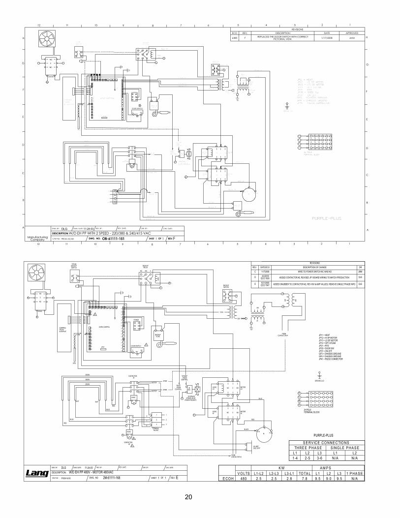
L1 L2 L3 L1 L21-4 2-5 3-6 N/A N/A
L1-L2 L2-L3 L3-L1 TO TA L L1 L2 L3 1 P HA S EE CO H 480 2.5 2.5 2.8 7.8 9.5 9.0 9.5 N/A
S E RV ICE CO NNE CTIO NSTHRE E P HA S E S ING LE P HA S E
V O LTSK W A M P S
PURPLE-PLUS
NONCC
DOOR SWITCH
C
A
240
24
12/24
NC
BACKUPRELAY
BACKUPTSTAT
BACKUPSWITCH
RTD
NO C
240V
A
C
STEAMBACKUPSWITCH
OVEN CONTROLCONTROLFRONT& DISPLAY
240POWER
JP41
B
240 480
AB
D
B A
C
24 POLETERMINAL BLOCK
GROUND LUG
CONTACTOR#2
24VAC
D
D
D
CL E
B
RED
BLUE
WHT WHT
BLUE
RED
T7-T4
T9
P1
"HEAT"FROM
CONTROL
D
L
1
2
3 3
2
1
XFMR
MOTOR
CONTACTOR#1
24VAC
HI-LIMITDISC STAT
TERMINALBLOCK
M
XFMR
MOTOR
NC C NO
NONC C
24VACLO
24VACHI
MOTORHI
MOTORLO
FROMCONTACTOR #1
2500W
BLUE
RED
BLACK
2500W
2500W
14
52
36
SOLENOIDSTEAM VALVE
(WHEN PRESENT)
"STEAM"FROM
CONTROL
24VAC
FROMCONTACTOR #1
D
B
D
DC
AB
JP11 JP12 JP13 JP14 JP15 JP16 JP17 JP18 JP19 JP20
JP2
JP1
JP4
JP3
JP24
JP23
JP22
JP21
2627
JP39
JP38
JP37
JP36
JP35
JP40
JP30
JP34
JP32
JP31
JP33
JP7
JP5
JP6
JP9
JP8
JP11 = HEATJP12 = HI SP MOTORJP13 = LO SP MOTORJP14 = OPT STEAMJP21 = RTDJP35 = DOOR SW
GP3 = CHASSIS GROUNDJP37 = ON-OFF
JP41 = RS232 CONNECTORGP4 = CHASSIS GROUND
11-24-03
24VAC
NO
C
NC
DWG. NO: SHEET OF
DWN. DATE :DWN. BY : CHK. BY :
DESCRIPTION: W/D EH PP 480V - MOTOR 480VAC2M-61111-168 REV:1 E1CAD FILE : FROM ACAD
CHK. DATE :REV. BY : REV. DATE :DLG
REVISIONS
REV. DATE/ECO DESCRIPTION OF CHANGE DR
C 1/17/2008 WIRE TO POWER SWITCH NC WAS NO JMM
D 4/2/2009ECO 7806 ADDED CONTACTOR #2, REVISED JP1 BOARD WIRING TO MATCH PRODUCTION DJS
E 5/21/2009ECO 7947 ADDED SNUBBER TO CONTACTOR #2, REV KW & AMP VALUES, REMOVE SINGLE PHASE INFO DJS

21
31
1
8
2
34
5
6
7
15
23
25
24
26 1920
21
22
1718
16
29
30See
Door Assembly
28 27
See Body Assembly
See ControllerAssembly
SeePanel Assembly
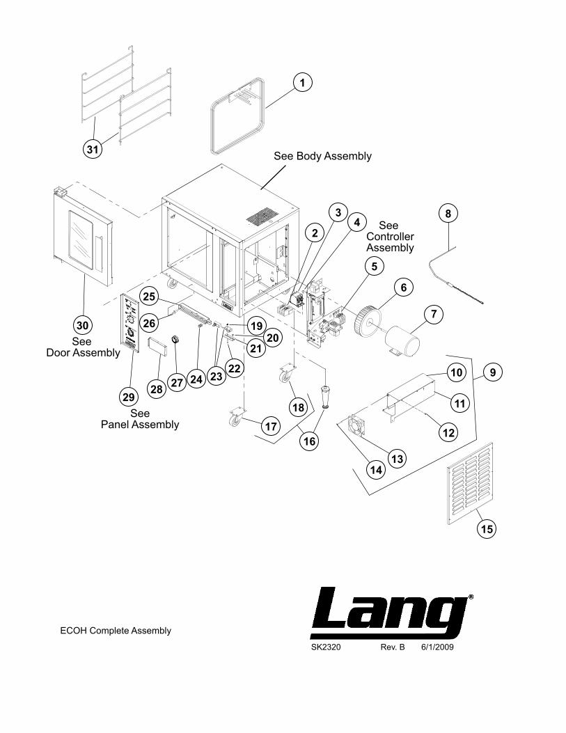
SK2320 Rev. B 6/1/2009
ECOH Complete Assembly
10
11
12
9
1314
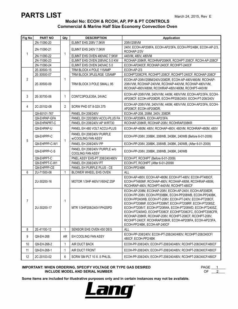
PARTS LIST March 24, 2015, Rev EModel No: ECOH & RCOH, AP, PP & PT CONTROLS
Commercial & Marine Half Size Economy Convection Oven
IMPORTANT: WHEN ORDERING, SPECIFY VOLTAGE OR TYPE GAS DESIRED PAGE 1 INCLUDE MODEL AND SERIAL NUMBER OF 2
Some items are included for illustrative purposes only and in certain instances may not be available.
Fig No PART NO Qty DESCRIPTION Application
1
2N-11090-20
1
ELMNT EHS 208V 7.5KW 208V/208VM
2N-11090-21 ELMNT EHS 240V 7.5KW 240V, ECOH-AP208FA, ECOH-AP2/3FA, ECOH-PP2/4BK, ECOH-AP-2/3, RCOHAP-2/3V
2N-11090-22 ELMNT EHS OVEN 480VAC 7.5KW 440VM, 480V, 480VM2N-11090-23 ELMNT EHS OVEN 208VAC 5.0 KW RCOHAP-208KR, RCOHRAP208KR, RCOHPT-208CF, RCOH-AP-208CF2N-11090-24 ELMNT EHS OVEN 240VAC 5.0 ECOH-AP240CF, RCOHAP-240CF, RCOHPT-240CF
2
2E-30500-15
1
TRM BLOCK 4 POLE 115AMP ECOH-AP-2/32E-30500-07 TRM BLOCK 3PLELRGE 125AMP ECOHPT208CFR, RCOHPT-208CF, RCOHPT-240CF, RCOHAP-208CF
2E-30500-09 TRM BLOCK 3 POLE SMALL 95ECOH-AP-208V/208M/240V/208DR, ECOH-AP-480V480/M, RCOHAP-208V/VM, RCOHAP-240VM, RCOHAP-440VM, RCOHAP-480V/VM, RCOHAP-480V/480M, RCOHRAP-480V/480M, RCOHPT-440VM
3 2E-30700-06 1 CONTC3POLE35A, 24VAC ECOH-AP-208V/VM, 240V/VM, 440M, 480V/VM, ECOH-AP2/3FA, ECOH-AP208CF, ECOH-AP208DR, ECOH-PP208/240V, ECOH-PT-208/240V
4 2C-20102-08 2 SCRW PHD ST 8-32X.375 ECOH-AP-208V/VM, 240V/VM, 440M, 480V/VM, ECOH-AP2/3FA, ECOH-AP208CF, ECOH-AP208DR,
5
Q9-60101-767
1
PANEL EH 208/240V ECOH-AP-208, 208M, 240V, 208DRQ9-EHPAP-GFA PANEL EH 220/380V ACCU-PLUS FA ECOH-AP208FA, ECOH-AP2/3FAQ9-EHPAPRT-C PANEL EH 208/240V AP W/RT30 RCOHAP-208KR, RCOHAP-208V, RCOHRAP208KRQ9-EHPAP-U PANEL EH 480 VOLT ACCU-PLUS ECOH-AP-480M, 480V, RCOHAP-480V, 480VM, RCOHRAP-480M, 480V
Q9-EHPPP-C PANEL EH 208/240V PURPLE w/COOLING FAN ASSY ECOH-PP-208V, 208BK, 208WB, 240BK, 240WB (Before 6-01-2009)
Q9-EHPPP-C-W1 PANEL EH 208/240V PP ECOH-PP-208V, 208BK, 208WB, 240BK, 240WB, (After 6-01-2009)
Q9-EHPPP-C-S PANEL EH 208/240V PURPLE w/o COOLING FAN ASSY ECOH-PP-208V, 208BK, 208WB, 240BK, 240WB
Q9-EHPPT-C PNEL ASSY EHS-PT 208/240/480V ECOH-PT, RCOHPT (Before 6-01-2009)Q9-EHPPT-C-W1 PANEL EH 208/240V PT ECOH-PT, RCOHPT (After 6-01-20090Q9-EHPPP-CE PANEL EH PURPLE PLUS - CE ECOH-PP2/4BK
6 2U-71500-06 1 BLOWER WHEEL EHS OVEN ALL
7
2U-30200-16
1
MOTOR 1/3HP 460V/1/60HZ 2SPECOH-AP-480V, ECOH-AP-480M, ECOH-PT-480V, ECOH-PT480CF, ECOH-PT480MF, RCOHAP-480V, RCOHAP-480M, RCOHRAP-480M, RCOHRAP-480V, RCOHPT-440VM, RCOHPT-480CF
2U-30200-17 MTR 1/3HP208/240V1PH2SPD
ECOH-AP-208M, ECOHAP-208V, ECOH-AP-240V, ECOH-AP208DR, ECOH-PP-208V, ECOH-PP208BK, ECOH-PP208WB, ECOH-PP240BK, ECOH-PP240WB, ECOH-PT-208V, ECOH-PT-240V, ECOH-PT208CF, ECOH-PT208MF, ECOH-PT208NT, ECOH-PT208RF, ECOH-PT208SZ, ECOH-PT208V7, ECOH-PT208WA, ECOH-PT208WD, ECOH-PT240SZ, ECOH-PT240WD, ECOHPT208CF, ECOHPT208CFC, ECOHPT208CFR, RCOHAP-208KR, RCOHAP-208V, RCOHPT-208CF, RCOHPT-208V, RCOHPT-240CF, RCOHRAP208KR, ECOH-AP208FA, ECOH-AP2/3FA, ECOH-PP2/4BK, ECOH-AP-240CF
8 2E-41100-12 1 SENSOR EHS OVEN 450 DEG ALL
9 Q9-EH-268 AR EH COOLING FAN ASSY ECOH-PP-208/240V, ECOH-PT-208/240/480V, RCOHPT-208/240CF/480CF, ECOH-PP2/4BK
10 Q9-EH-268-2 1 AIR DUCT BACK ECOH-PP-208/240V, ECOH-PT-208/240/480V, RCOHPT-208/240CF/480CF11 Q9-EH-268-1 1 AIR DUCT FRONT ECOH-PP-208/240V, ECOH-PT-208/240/480V, RCOHPT-208/240CF/480CF
12 2C-20103-02 6 SCRW SM PLT 10 X .5 PHLSL ECOH-PP-208/240V, ECOH-PT-208/240/480V, RCOHPT-208/240CF/480CF
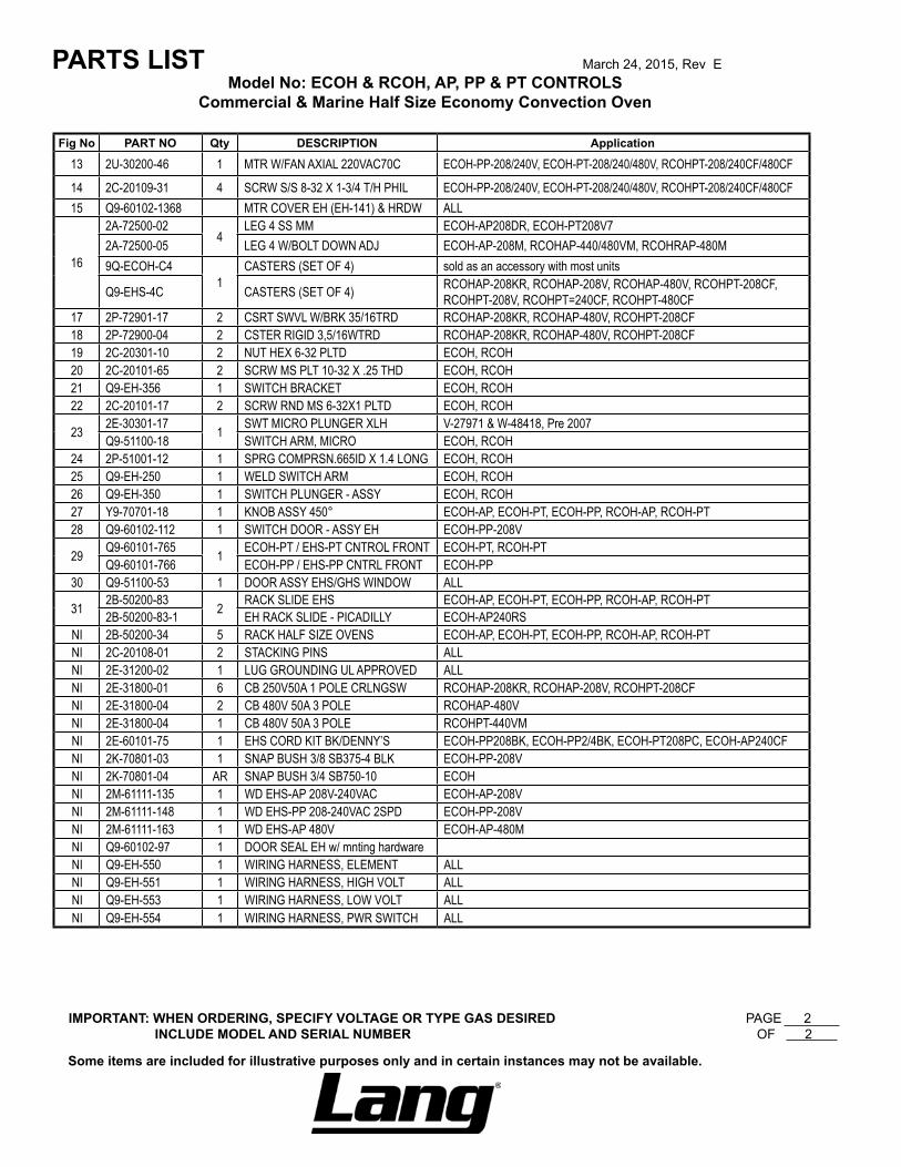
IMPORTANT: WHEN ORDERING, SPECIFY VOLTAGE OR TYPE GAS DESIRED PAGE 2 INCLUDE MODEL AND SERIAL NUMBER OF 2
Some items are included for illustrative purposes only and in certain instances may not be available.
Fig No PART NO Qty DESCRIPTION Application
13 2U-30200-46 1 MTR W/FAN AXIAL 220VAC70C ECOH-PP-208/240V, ECOH-PT-208/240/480V, RCOHPT-208/240CF/480CF
14 2C-20109-31 4 SCRW S/S 8-32 X 1-3/4 T/H PHIL ECOH-PP-208/240V, ECOH-PT-208/240/480V, RCOHPT-208/240CF/480CF15 Q9-60102-1368 MTR COVER EH (EH-141) & HRDW ALL
16
2A-72500-024
LEG 4 SS MM ECOH-AP208DR, ECOH-PT208V72A-72500-05 LEG 4 W/BOLT DOWN ADJ ECOH-AP-208M, RCOHAP-440/480VM, RCOHRAP-480M9Q-ECOH-C4
1CASTERS (SET OF 4) sold as an accessory with most units
Q9-EHS-4C CASTERS (SET OF 4) RCOHAP-208KR, RCOHAP-208V, RCOHAP-480V, RCOHPT-208CF, RCOHPT-208V, RCOHPT=240CF, RCOHPT-480CF
17 2P-72901-17 2 CSRT SWVL W/BRK 35/16TRD RCOHAP-208KR, RCOHAP-480V, RCOHPT-208CF18 2P-72900-04 2 CSTER RIGID 3,5/16WTRD RCOHAP-208KR, RCOHAP-480V, RCOHPT-208CF19 2C-20301-10 2 NUT HEX 6-32 PLTD ECOH, RCOH20 2C-20101-65 2 SCRW MS PLT 10-32 X .25 THD ECOH, RCOH21 Q9-EH-356 1 SWITCH BRACKET ECOH, RCOH22 2C-20101-17 2 SCRW RND MS 6-32X1 PLTD ECOH, RCOH
23 2E-30301-17 1 SWT MICRO PLUNGER XLH V-27971 & W-48418, Pre 2007Q9-51100-18 SWITCH ARM, MICRO ECOH, RCOH
24 2P-51001-12 1 SPRG COMPRSN.665ID X 1.4 LONG ECOH, RCOH25 Q9-EH-250 1 WELD SWITCH ARM ECOH, RCOH26 Q9-EH-350 1 SWITCH PLUNGER - ASSY ECOH, RCOH27 Y9-70701-18 1 KNOB ASSY 450° ECOH-AP, ECOH-PT, ECOH-PP, RCOH-AP, RCOH-PT28 Q9-60102-112 1 SWITCH DOOR - ASSY EH ECOH-PP-208V
29 Q9-60101-765 1 ECOH-PT / EHS-PT CNTROL FRONT ECOH-PT, RCOH-PTQ9-60101-766 ECOH-PP / EHS-PP CNTRL FRONT ECOH-PP
30 Q9-51100-53 1 DOOR ASSY EHS/GHS WINDOW ALL
31 2B-50200-83 2 RACK SLIDE EHS ECOH-AP, ECOH-PT, ECOH-PP, RCOH-AP, RCOH-PT2B-50200-83-1 EH RACK SLIDE - PICADILLY ECOH-AP240RS
NI 2B-50200-34 5 RACK HALF SIZE OVENS ECOH-AP, ECOH-PT, ECOH-PP, RCOH-AP, RCOH-PTNI 2C-20108-01 2 STACKING PINS ALLNI 2E-31200-02 1 LUG GROUNDING UL APPROVED ALLNI 2E-31800-01 6 CB 250V50A 1 POLE CRLNGSW RCOHAP-208KR, RCOHAP-208V, RCOHPT-208CFNI 2E-31800-04 2 CB 480V 50A 3 POLE RCOHAP-480VNI 2E-31800-04 1 CB 480V 50A 3 POLE RCOHPT-440VMNI 2E-60101-75 1 EHS CORD KIT BK/DENNY’S ECOH-PP208BK, ECOH-PP2/4BK, ECOH-PT208PC, ECOH-AP240CFNI 2K-70801-03 1 SNAP BUSH 3/8 SB375-4 BLK ECOH-PP-208VNI 2K-70801-04 AR SNAP BUSH 3/4 SB750-10 ECOHNI 2M-61111-135 1 WD EHS-AP 208V-240VAC ECOH-AP-208VNI 2M-61111-148 1 WD EHS-PP 208-240VAC 2SPD ECOH-PP-208VNI 2M-61111-163 1 WD EHS-AP 480V ECOH-AP-480MNI Q9-60102-97 1 DOOR SEAL EH w/ mnting hardwareNI Q9-EH-550 1 WIRING HARNESS, ELEMENT ALLNI Q9-EH-551 1 WIRING HARNESS, HIGH VOLT ALLNI Q9-EH-553 1 WIRING HARNESS, LOW VOLT ALLNI Q9-EH-554 1 WIRING HARNESS, PWR SWITCH ALL
PARTS LIST March 24, 2015, Rev EModel No: ECOH & RCOH, AP, PP & PT CONTROLS
Commercial & Marine Half Size Economy Convection Oven
15
14
89
10
11
12
13
2
3
45
67
16
17
18
1
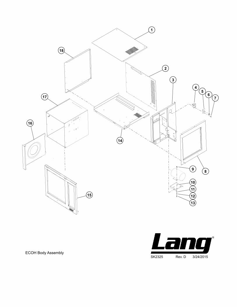
SK2325 Rev. D 3/24/2015ECOH Body Assembly
Model No: ECOH & RCOH, AP, PP & PT BODY PANELS Commercial & Marine Half Size Economy Convection Oven
PARTS LIST March 24, 2015, Rev E
IMPORTANT: WHEN ORDERING, SPECIFY VOLTAGE OR TYPE GAS DESIRED PAGE 1 INCLUDE MODEL AND SERIAL NUMBER OF 1
Some items are included for illustrative purposes only and in certain instances may not be available.
DescriptionPart
NumberKey
Number
1 Q9-60102-136 1 BODY TOP EH & HRDW ALL 2 Q9-60102-1361 1 BODY BACK EH & HRDW ALL 3 Q9-EH-119-2 1 FIREWALL - ASSY ALL 4 Q9-EH-W1237 1 SAFETY STAT BOX ASSY ALL EXCEPT MARINE APPLICATIONS 5 Q9-EH-136 1 SAFETY STAT COVER ALL 6 2K-70801-04 1 SNAP BUSH 3/4 SB750-10 BLK ALL 7 2C-20103-02 2 SCRW SM PLT 10 X .5 PHLSL ALL 8 Q9-60102-1364 1 BODY R/H SIDE EH & HRDW ALL 9 2C-20104-41 4 SCRW MACH 1/4-20X5/8 H/H ALL 10 Q9-EH-209 1 MOTOR MOUNT ALL 11 2C-20202-08 4 WSHR PLT 5/16 LOCK SPLIT ALL 12 2C-20201-09 4 WSHR PLT 5/16 FLAT SAE ALL 13 2C-20301-06 4 NUT HEX 5/16-18 PLTD ALL 14 Q9-EH-104-2 1 BOTTOM SPOT WELD ALL 15 Q9-EH-215-2 1 FRONT - ASSY REVERSIBLE ALL 16 Q9-EH-452-2 1 BAFFLE STD ALL 16 Q9-EH-452-3 1 BAFFLE ASSY STEAM STEAM 17 Q9-EH-374-3 1 CAN ASSY STD -[NEW RACK ALL 18 Q9-60102-1365 1 BODY L/H SIDE EH & HRDW ALL
Qty Per
SK2321 Rev. A 3/1/2012
ECOH, RCOH Door Assembly
5
6
43
21
10
8
11
12
11
10
5
13
14
7
8
9
MARINE APPLICATION
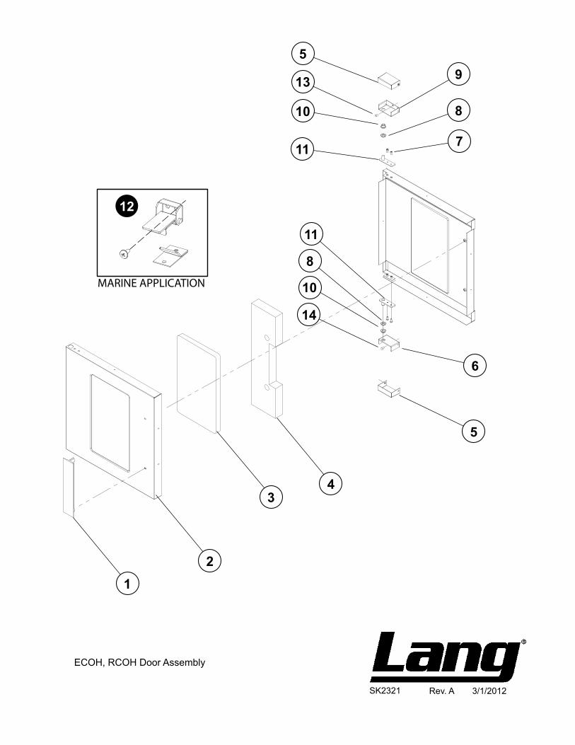
Model No: ECOH & RCOH, AP, PP & PT DOOR ASSEMBLY Commercial & Marine Half Size Economy Convection Oven
PARTS LIST March 24, 2015, Rev E
IMPORTANT: WHEN ORDERING, SPECIFY VOLTAGE OR TYPE GAS DESIRED PAGE 1 INCLUDE MODEL AND SERIAL NUMBER OF 1
Some items are included for illustrative purposes only and in certain instances may not be available.
DescriptionPart
NumberKey
Number
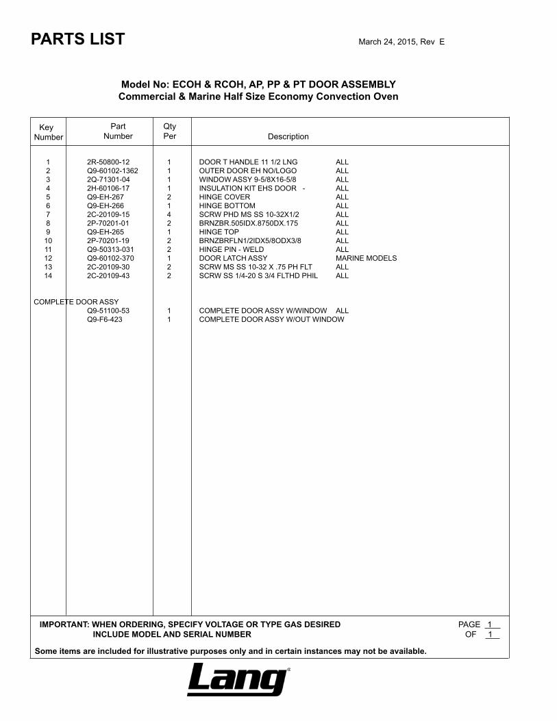
1 2R-50800-12 1 DOOR T HANDLE 11 1/2 LNG ALL 2 Q9-60102-1362 1 OUTER DOOR EH NO/LOGO ALL 3 2Q-71301-04 1 WINDOW ASSY 9-5/8X16-5/8 ALL 4 2H-60106-17 1 INSULATION KIT EHS DOOR - ALL 5 Q9-EH-267 2 HINGE COVER ALL 6 Q9-EH-266 1 HINGE BOTTOM ALL 7 2C-20109-15 4 SCRW PHD MS SS 10-32X1/2 ALL 8 2P-70201-01 2 BRNZBR.505IDX.8750DX.175 ALL 9 Q9-EH-265 1 HINGE TOP ALL 10 2P-70201-19 2 BRNZBRFLN1/2IDX5/8ODX3/8 ALL 11 Q9-50313-031 2 HINGE PIN - WELD ALL 12 Q9-60102-370 1 DOOR LATCH ASSY MARINE MODELS 13 2C-20109-30 2 SCRW MS SS 10-32 X .75 PH FLT ALL 14 2C-20109-43 2 SCRW SS 1/4-20 S 3/4 FLTHD PHIL ALL
COMPLETE DOOR ASSY Q9-51100-53 1 COMPLETE DOOR ASSY W/WINDOW ALL Q9-F6-423 1 COMPLETE DOOR ASSY W/OUT WINDOW
Qty Per
SK2324 Rev. A 6/21/2010
ECOH-PPPurple Plus Controller
ECOH-PT & RCOH-PTPlatinum Controller
7
9
11
11 12
6
76
5
5
3
3
8
8
2
2
1
10
1
4
10
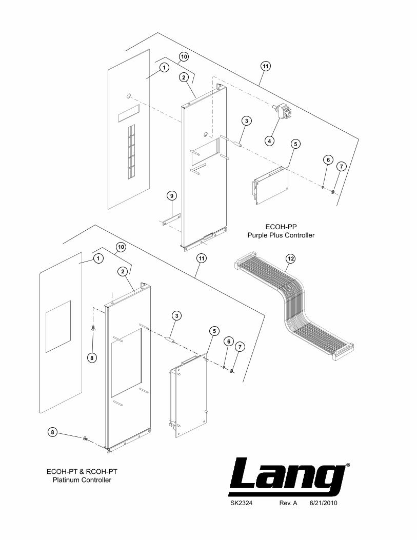
Model No: ECOH & RCOH, PP & PT CONTROL ASSEMBLY Commercial & Marine Half Size Economy Convection Oven
PARTS LIST March 24, 2015, Rev E
IMPORTANT: WHEN ORDERING, SPECIFY VOLTAGE OR TYPE GAS DESIRED PAGE INCLUDE MODEL AND SERIAL NUMBER OF
Some items are included for illustrative purposes only and in certain instances may not be available.
DescriptionPart
NumberKey
Number
1 2M-60301-117 1 SWITCH LBL EH 4X20 ECOH-PP 2M-60301-118 1 SWITCH LBL EH PLATINUM ECOH-PT, RCOHPT 2 Q9-60101-7665 1 ECOH-PP / EHS-PP CNTRL FRNT W/PROTO ECOH-PP Q9-EH-516-1 1 CONTORL PANEL - EH-PT ECOH-PT-208V 3 2A-20504-01 4 SPACER NYLON #6 1/4 X 7/8 ECOH-PP 2A-20504-02 4 SPACER NYLON #6 1/4 X 1” ECOH-PT, RCOH-PT 4 2E-30303-06 1 SWT TOG ON-ON DPDT BLK ECOH-PP, ECOH-PT, RCOH-PT 5 2J-40102-A24 1 DSPLY 4X20 MDL.DA170-001 (NO CABLE) ECOH-PP 2J-40102-25 1 DSPLY 320X240 DB170-001 ECOH-PT, RCOH-PT 6 2C-20205-02 4 .140#6IDX.2500DX.032 ALL 7 2C-20301-10 2 NUT HEX 6-32 PLTD ECOH-PP 2C-20301-10 4 NUT HEX 6-32 PLTD ECOH-PT, RCOH-PT 8 2C-20103-02 4 SCRW SM PLT 10 X .5 PHLSL TP A ALL 9 Q9-EH-519 1 COMPUTER STRIP HOLDER ECOH-PP 10 Q9-60101-7661 1 ECOH-PP / EHS-PP FRNT W/LABEL ECOH-PP Q9-60101-7662 1 ECOH-PT / EHS-PT FRNT W/LABEL ECOH-PT, RCOH-PT 11 Q9-60101-765 1 ECOH-PT / EHS-PT CONTROL FRONT ECOH-PT, RCOH-PT Q9-60101-766 1 ECOH-PP / EHS-PP CONTROL FRONT ECOH-PP 12 2J-31110-13 1 CABLE ASSY - RIBBON 12 PT ECOH-PP, ECOH-PT, RCOH-PT NI 2M-60301-128 1 PRODUCT STRIP PURP COMP ECOH-PP 2M-60301-W128 1 PRODUCT STRIP PURP BK ECOH-PP208BK, ECOH-PP240BK NI OB-60301-46 1 OBS PRDCT STRIP-BLU/PURP COMPH ECOH-PP
1 1
Qty Per
12221
2
3
48
7
6
9
10
14
18
19
15
12
5
11
9
1716
13
20
SK2323 Rev. A 7/6/2010
ECOH PP/PT Controller Panel
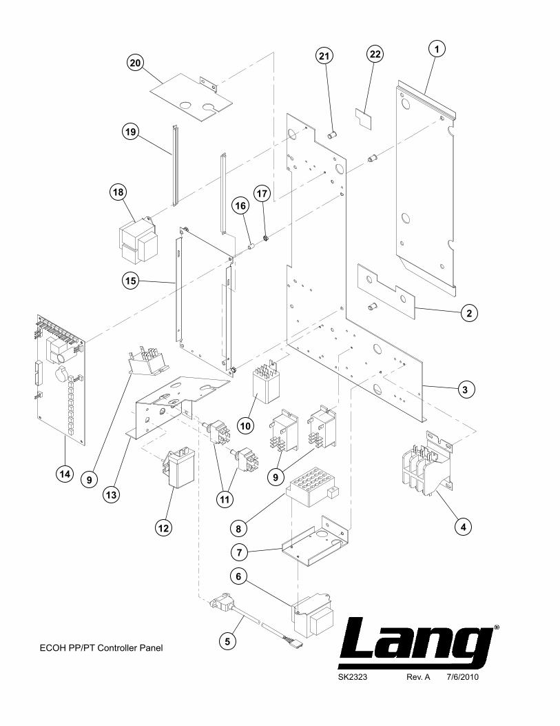
Model No: ECOH & RCOH, PP & PT CONTROL PANEL ASSEMBLY Commercial & Marine Half Size Economy Convection Oven
PARTS LIST March 24, 2015, Rev E
IMPORTANT: WHEN ORDERING, SPECIFY VOLTAGE OR TYPE GAS DESIRED PAGE INCLUDE MODEL AND SERIAL NUMBER OF
Some items are included for illustrative purposes only and in certain instances may not be available.
DescriptionPart
NumberKey
Number
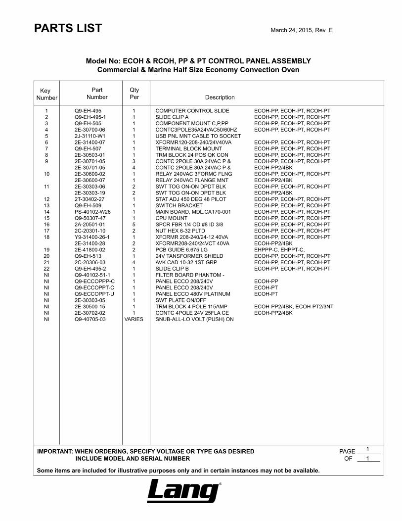
1 Q9-EH-495 1 COMPUTER CONTROL SLIDE ECOH-PP, ECOH-PT, RCOH-PT 2 Q9-EH-495-1 1 SLIDE CLIP A ECOH-PP, ECOH-PT, RCOH-PT 3 Q9-EH-505 1 COMPONENT MOUNT C,P,PP ECOH-PP, ECOH-PT, RCOH-PT 4 2E-30700-06 1 CONTC3POLE35A24VAC50/60HZ ECOH-PP, ECOH-PT, RCOH-PT 5 2J-31110-W1 1 USB PNL MNT CABLE TO SOCKET 6 2E-31400-07 1 XFORMR120-208-240/24V40VA ECOH-PP, ECOH-PT, RCOH-PT 7 Q9-EH-507 1 TERMINAL BLOCK MOUNT ECOH-PP, ECOH-PT, RCOH-PT 8 2E-30503-01 1 TRM BLOCK 24 POS QK CON ECOH-PP, ECOH-PT, RCOH-PT 9 2E-30701-05 3 CONTC 2POLE 30A 24VAC P & ECOH-PP, ECOH-PT, RCOH-PT 2E-30701-05 4 CONTC 2POLE 30A 24VAC P & ECOH-PP2/4BK 10 2E-30600-02 1 RELAY 240VAC 3FORMC FLNG ECOH-PP, ECOH-PT, RCOH-PT 2E-30600-07 1 RELAY 240VAC FLANGE MNT ECOH-PP2/4BK 11 2E-30303-06 2 SWT TOG ON-ON DPDT BLK ECOH-PP, ECOH-PT, RCOH-PT 2E-30303-19 2 SWT TOG ON-ON DPDT BLK ECOH-PP2/4BK 12 2T-30402-27 1 STAT ADJ 450 DEG 48 PILOT ECOH-PP, ECOH-PT, RCOH-PT 13 Q9-EH-509 1 SWITCH BRACKET ECOH-PP, ECOH-PT, RCOH-PT 14 PS-40102-W26 1 MAIN BOARD, MDL.CA170-001 ECOH-PP, ECOH-PT, RCOH-PT 15 Q9-50307-47 1 CPU MOUNT ECOH-PP, ECOH-PT, RCOH-PT 16 2A-20501-01 5 SPCR FBR 1/4 OD #8 ID 3/8 ECOH-PP, ECOH-PT, RCOH-PT 17 2C-20301-10 2 NUT HEX 6-32 PLTD ECOH-PP, ECOH-PT, RCOH-PT 18 Y9-31400-26-1 1 XFORMR 208-240/24-12 40VA ECOH-PP, ECOH-PT, RCOH-PT 2E-31400-28 2 XFORMR208-240/24VCT 40VA ECOH-PP2/4BK 19 2E-41800-02 2 PCB GUIDE 6.675 LG EHPPP-C, EHPPT-C, 20 Q9-EH-513 1 24V TANSFORMER SHIELD ECOH-PP, ECOH-PT, RCOH-PT 21 2C-20306-03 4 AVK CAD 10-32 1ST GRP ECOH-PP, ECOH-PT, RCOH-PT 22 Q9-EH-495-2 1 SLIDE CLIP B ECOH-PP, ECOH-PT, RCOH-PT NI Q9-40102-51-1 1 FILTER BOARD PHANTOM - NI Q9-ECCOPPP-C 1 PANEL ECCO 208/240V ECOH-PP NI Q9-ECCOPPT-C 1 PANEL ECCO 208/240V ECOH-PT NI Q9-ECCOPPT-U 1 PANEL ECCO 480V PLATINUM ECOH-PT NI 2E-30303-05 1 SWT PLATE ON/OFF NI 2E-30500-15 1 TRM BLOCK 4 POLE 115AMP ECOH-PP2/4BK, ECOH-PT2/3NT NI 2E-30702-02 1 CONTC 4POLE 24V 25FLA CE ECOH-PP2/4BK NI Q9-40705-03 VARIES SNUB-ALL-LO VOLT (PUSH) ON
1 1
Qty Per