Embed Size (px)
Citation preview
ELECTRIC MACHINES - OPENLAB - 0.2 kW
AUTOMATIC CONFIGURATION
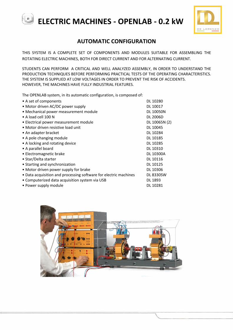
THIS SYSTEM IS A COMPLETE SET OF COMPONENTS AND MODULES SUITABLE FOR ASSEMBLING THE
ROTATING ELECTRIC MACHINES, BOTH FOR DIRECT CURRENT AND FOR ALTERNATING CURRENT.
STUDENTS CAN PERFORM A CRITICAL AND WELL ANALYZED ASSEMBLY, IN ORDER TO UNDERSTAND THE PRODUCTION TECHNIQUES BEFORE PERFORMING PRACTICAL TESTS OF THE OPERATING CHARACTERISTICS. THE SYSTEM IS SUPPLIED AT LOW VOLTAGES IN ORDER TO PREVENT THE RISK OF ACCIDENTS. HOWEVER, THE MACHINES HAVE FULLY INDUSTRIAL FEATURES. The OPENLAB system, in its automatic configuration, is composed of:
• A set of components DL 10280 • Motor driven AC/DC power supply DL 10017 • Mechanical power measurement module DL 10050N • A load cell 100 N DL 2006D • Electrical power measurement module DL 10065N (2) • Motor driven resistive load unit DL 10045 • An adapter bracket DL 10284 • A pole changing module DL 10185 • A locking and rotating device DL 10285 • A parallel board DL 10310 • Electromagnetic brake DL 10300A • Star/Delta starter DL 10116 • Starting and synchronization DL 10125 • Motor driven power supply for brake DL 10306 • Data acquisition and processing software for electric machines DL 8330SW • Computerized data acquisition system via USB DL 1893 • Power supply module DL 10281
ELECTRIC MACHINES - OPENLAB - 0.2 kW
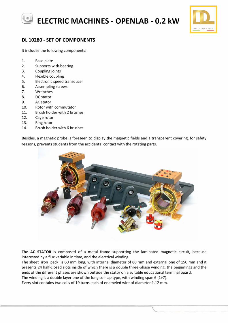
DL 10280 - SET OF COMPONENTS
It includes the following components: 1. Base plate 2. Supports with bearing 3. Coupling joints 4. Flexible coupling 5. Electronic speed transducer 6. Assembling screws 7. Wrenches 8. DC stator 9. AC stator 10. Rotor with commutator 11. Brush holder with 2 brushes 12. Cage rotor 13. Ring rotor 14. Brush holder with 6 brushes Besides, a magnetic probe is foreseen to display the magnetic fields and a transparent covering, for safety
reasons, prevents students from the accidental contact with the rotating parts.
The AC STATOR is composed of a metal frame supporting the laminated magnetic circuit, because interested by a flux variable in time, and the electrical winding. The sheet iron pack is 60 mm long, with internal diameter of 80 mm and external one of 150 mm and it presents 24 half-closed slots inside of which there is a double three-phase winding: the beginnings and the ends of the different phases are shown outside the stator on a suitable educational terminal board. The winding is a double layer one of the long coil lap type, with winding span 6 (1÷7). Every slot contains two coils of 19 turns each of enameled wire of diameter 1.12 mm.
ELECTRIC MACHINES - OPENLAB - 0.2 kW
The SQUIRREL CAGE ROTOR is composed of a shaft to which a pack of magnetic sheet irons is fixed, where the slots suitable to contain the rotor winding are set. The sheet iron pack is 60 mm long, with external diameter of about 78 mm. To avoid the phenomenon of the motor crawling in starting phase and to reduce the noise, the slots are inclined as regards the stator ones. The rotor winding is composed of the squirrel cage. The cage is carried out by setting in every rotor slot some conducting bars that are closed in short-circuit at both ends by means of some conducting rings. The rotor winding can be therefore considered a multi-phase winding, with a single conductor for pole-phase, so it does not present its proper pole number but it assumes one that is equal to the stator winding one. The RING ROTOR is composed of a shaft to which the collector rings and a magnetic sheet iron pack are fixed: the iron pack has 21 semi-closed slots suitable to contain the winding. The sheet iron pack is 60 mm long, with external diameter of about 78 mm. To avoid a noisy mechanical running the rotor slots are inclined as regards the stator ones. The rotor winding is composed of coils and it is two pole three-phase. The winding is a double layer one of the long coil lap type, with winding span 9 (1-10). Every slot contains two coils of 8 turns each of enameled wire of diameter 1.5 mm. The winding is star connected and it is subordinate to the collector rings while the star centre is internal and not accessible. The terminals of the rotor winding are accessible by means of the collector rings on which the bushes supported by a brush holder graze. The brushes are two for each phase and they are subordinate to an external terminal board that shows the synoptic of the rotor winding. The DC STATOR is composed of a metal frame supporting the laminated magnetic circuit, with 2 main poles and 2 inter poles, and the electrical windings. The sheet iron pack is 60 mm long, with internal diameter of 80 mm. On the poles the coils are wound whose terminals are shown on a suitable educational terminal board. The DC ROTOR is composed of a shaft to which the segment commutator is fixed and of a magnetic sheet iron pack where 20 semi-closed slots suitable to contain the electrical winding are set. The sheet iron pack is 60 mm long, with external diameter of about 80 mm. The winding is a double layer one of the long coil lap type, with winding span 9 (1÷10). Every slot contains two coils with two sections of 5+5 turns carried out with enameled wire of diameter 1.12 mm. The winding is subordinate to the 40 segments of the commutator on which two brushes are supported by a brush holder graze. The brushes are subordinate to terminals set on two external boards that show the synoptic of the rotor winding.
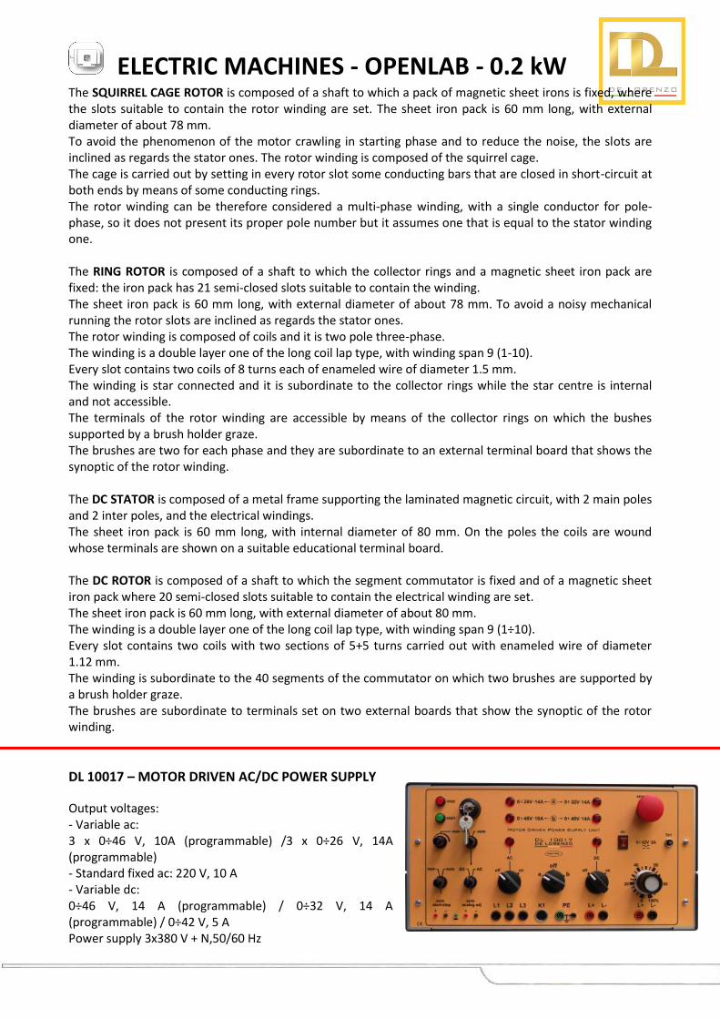
DL 10017 – MOTOR DRIVEN AC/DC POWER SUPPLY
Output voltages: - Variable ac: 3 x 0÷46 V, 10A (programmable) /3 x 0÷26 V, 14A (programmable) - Standard fixed ac: 220 V, 10 A - Variable dc: 0÷46 V, 14 A (programmable) / 0÷32 V, 14 A (programmable) / 0÷42 V, 5 A Power supply 3x380 V + N,50/60 Hz
ELECTRIC MACHINES - OPENLAB - 0.2 kW
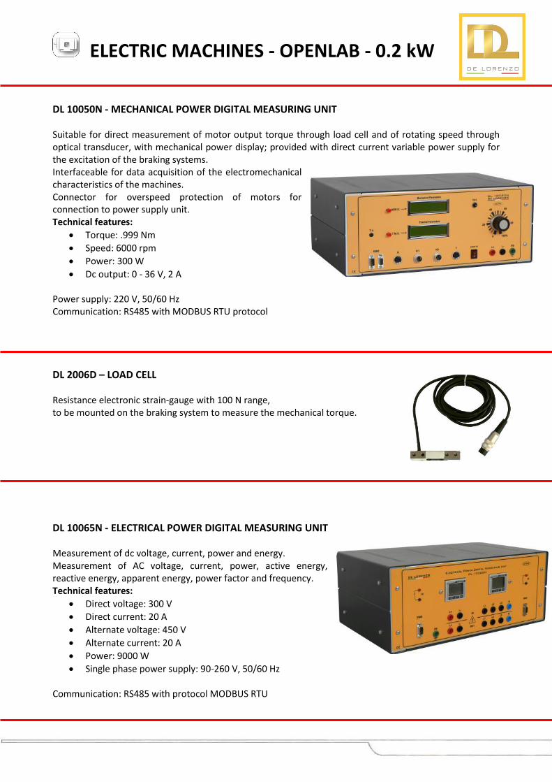
DL 10050N - MECHANICAL POWER DIGITAL MEASURING UNIT Suitable for direct measurement of motor output torque through load cell and of rotating speed through optical transducer, with mechanical power display; provided with direct current variable power supply for the excitation of the braking systems. Interfaceable for data acquisition of the electromechanical characteristics of the machines. Connector for overspeed protection of motors for connection to power supply unit. Technical features:
Torque: .999 Nm
Speed: 6000 rpm
Power: 300 W
Dc output: 0 - 36 V, 2 A Power supply: 220 V, 50/60 Hz Communication: RS485 with MODBUS RTU protocol
DL 2006D – LOAD CELL Resistance electronic strain-gauge with 100 N range, to be mounted on the braking system to measure the mechanical torque.
DL 10065N - ELECTRICAL POWER DIGITAL MEASURING UNIT Measurement of dc voltage, current, power and energy. Measurement of AC voltage, current, power, active energy, reactive energy, apparent energy, power factor and frequency. Technical features:
Direct voltage: 300 V
Direct current: 20 A
Alternate voltage: 450 V
Alternate current: 20 A
Power: 9000 W
Single phase power supply: 90-260 V, 50/60 Hz Communication: RS485 with protocol MODBUS RTU
ELECTRIC MACHINES - OPENLAB - 0.2 kW
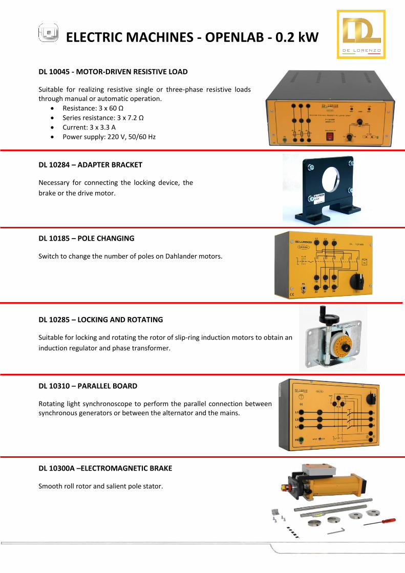
DL 10045 - MOTOR-DRIVEN RESISTIVE LOAD
Suitable for realizing resistive single or three-phase resistive loads through manual or automatic operation.
Resistance: 3 x 60 Ω
Series resistance: 3 x 7.2 Ω
Current: 3 x 3.3 A
Power supply: 220 V, 50/60 Hz
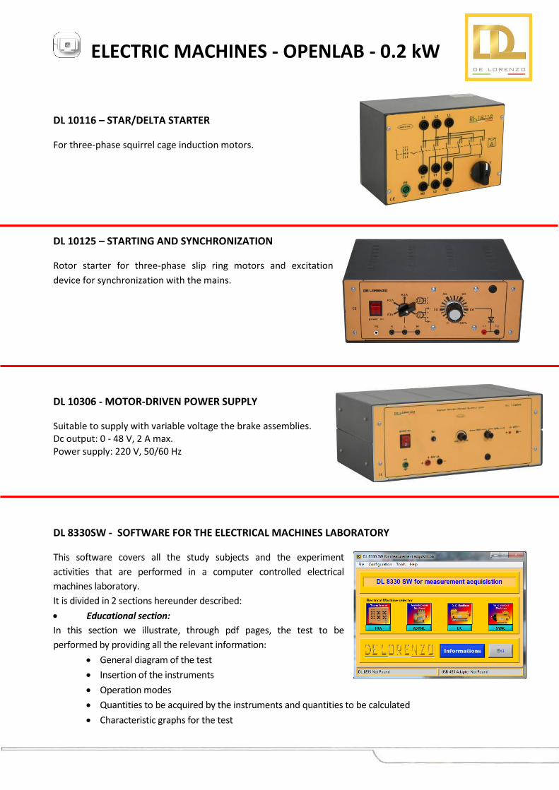
DL 10284 – ADAPTER BRACKET
Necessary for connecting the locking device, the
brake or the drive motor.
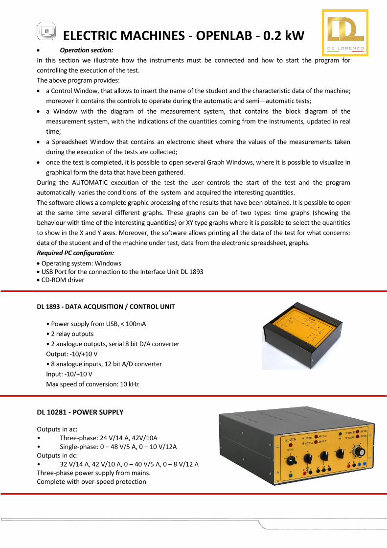
DL 10185 – POLE CHANGING
Switch to change the number of poles on Dahlander motors.
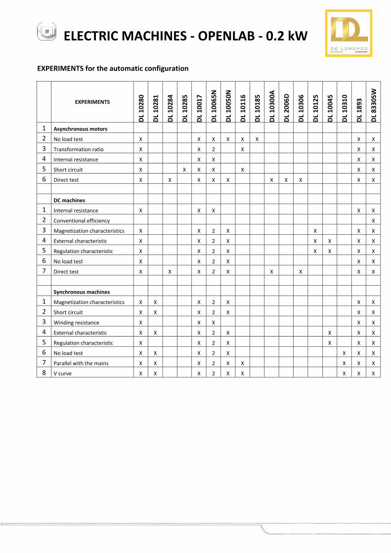
DL 10285 – LOCKING AND ROTATING
Suitable for locking and rotating the rotor of slip-ring induction motors to obtain an
induction regulator and phase transformer.
DL 10310 – PARALLEL BOARD
Rotating light synchronoscope to perform the parallel connection between synchronous generators or between the alternator and the mains.
DL 10300A –ELECTROMAGNETIC BRAKE
Smooth roll rotor and salient pole stator.
ELECTRIC MACHINES - OPENLAB - 0.2 kW
DL 10116 – STAR/DELTA STARTER
For three-phase squirrel cage induction motors.
DL 10125 – STARTING AND SYNCHRONIZATION
Rotor starter for three-phase slip ring motors and excitation
device for synchronization with the mains.
DL 10306 - MOTOR-DRIVEN POWER SUPPLY
Suitable to supply with variable voltage the brake assemblies. Dc output: 0 - 48 V, 2 A max. Power supply: 220 V, 50/60 Hz
DL 8330SW - SOFTWARE FOR THE ELECTRICAL MACHINES LABORATORY
This software covers all the study subjects and the experiment
activities that are performed in a computer controlled electrical
machines laboratory.
It is divided in 2 sections hereunder described:
Educational section:
In this section we illustrate, through pdf pages, the test to be
performed by providing all the relevant information:
General diagram of the test
Insertion of the instruments
Operation modes
Quantities to be acquired by the instruments and quantities to be calculated
Characteristic graphs for the test
ELECTRIC MACHINES - OPENLAB - 0.2 kW
Operation section:
In this section we illustrate how the instruments must be connected and how to start the program for
controlling the execution of the test.
The above program provides:
a Control Window, that allows to insert the name of the student and the characteristic data of the machine;
moreover it contains the controls to operate during the automatic and semi—automatic tests;
a Window with the diagram of the measurement system, that contains the block diagram of the
measurement system, with the indications of the quantities coming from the instruments, updated in real
time;
a Spreadsheet Window that contains an electronic sheet where the values of the measurements taken
during the execution of the tests are collected;
once the test is completed, it is possible to open several Graph Windows, where it is possible to visualize in
graphical form the data that have been gathered.
During the AUTOMATIC execution of the test the user controls the start of the test and the program
automatically varies the conditions of the system and acquired the interesting quantities.
The software allows a complete graphic processing of the results that have been obtained. It is possible to open
at the same time several different graphs. These graphs can be of two types: time graphs (showing the
behaviour with time of the interesting quantities) or XY type graphs where it is possible to select the quantities
to show in the X and Y axes. Moreover, the software allows printing all the data of the test for what concerns:
data of the student and of the machine under test, data from the electronic spreadsheet, graphs.
Required PC configuration:
Operating system: Windows USB Port for the connection to the Interface Unit DL 1893 CD-ROM driver
DL 1893 - DATA ACQUISITION / CONTROL UNIT
• Power supply from USB, < 100mA
• 2 relay outputs
• 2 analogue outputs, serial 8 bit D/A converter
Output: -10/+10 V
• 8 analogue inputs, 12 bit A/D converter
Input: -10/+10 V
Max speed of conversion: 10 kHz
DL 10281 - POWER SUPPLY
Outputs in ac: • Three-phase: 24 V/14 A, 42V/10A • Single-phase: 0 – 48 V/5 A, 0 – 10 V/12A Outputs in dc: • 32 V/14 A, 42 V/10 A, 0 – 40 V/5 A, 0 – 8 V/12 A Three-phase power supply from mains. Complete with over-speed protection
ELECTRIC MACHINES - OPENLAB - 0.2 kW
EXPERIMENTS for the automatic configuration
EXPERIMENTS
DL
10
28
0
DL
10
28
1
DL
10
28
4
DL
10
28
5
DL
10
01
7
DL
10
06
5N
DL
10
05
0N
DL
10
11
6
DL
10
18
5
DL
10
30
0A
DL
20
06
D
DL
10
30
6
DL
10
12
5
DL
10
04
5
DL
10
31
0
DL
18
93
DL
83
30
SW
1 Asynchronous motors
2 No load test X X X X X X X X
3 Transformation ratio X X 2 X X X
4 Internal resistance X X X X X
5 Short circuit X X X X X X X
6 Direct test X X X X X X X X X X
DC machines
1 Internal resistance X X X X X
2 Conventional efficiency X
3 Magnetization characteristics X X 2 X X X X
4 External characteristic X X 2 X X X X X
5 Regulation characteristic X X 2 X X X X X
6 No load test X X 2 X X X
7 Direct test X X X 2 X X X X X
Synchronous machines
1 Magnetization characteristics X X X 2 X X X
2 Short circuit X X X 2 X X X
3 Winding resistance X X X X X
4 External characteristic X X X 2 X X X X
5 Regulation characteristic X X 2 X X X X
6 No load test X X X 2 X X X X
7 Parallel with the mains X X X 2 X X X X X
8 V curve X X X 2 X X X X X