Embed Size (px)
Citation preview

NOVEMBER 21, 1914] ELECTRIC RAILWAY JOURNAL 1153
The Chicago, Milwaukee &Electrification
St. Paul
The Final Plans Have Been :\Iade and the Contracts Placed for the Electrification of lIS l\tliles of Trunk Line-Locomotives Weighing 260 Tons and Using Regenerative Control Will Be Used-Four Substations
'ViII Supply SOOO-Volt Direct Current to a Double Overhead Trolley \Vire
W.ith the placing, last week, of the contract for theelectrical equipment for the Chicago, Milwaukee & St.Paul electrification there has been taken one of themost important steps in the history of the supersessionof steam by electricity. In this instance electricaloperation has been adopted, not because of the smokenuisance, the high cost of terminals, the congestion oftraffic, or any of the dozen other impelling but peculiarly local causes that have necessitated past installations, but rather because of the accumulated evidence as to the normal operating economies that maybe expected from the use of the more modern form ofmotive power with low-priced hydroelectric energy.
labor and material necessary to complete the first 113mile division will cost approximately $3,000,000. Itis also estimated that the complete electrification, comprising 440 miles, will cost approximately $12,000,000,but the change in motive power is expected to resultin a saving of 25 per cent over the costs involved bythe present system of operation.
With regard to route mileage, this electrification isthe first step in a scheme which, when completed, willvery greatly exceed anything that has heretofore beenattempted. The immediate program calls for the electrification of 113 miles of line between Three Forks andDeer Lodge, Mont., as shown in the accompanying map.
e., M. & ST. P. ELECTRIFICATION-MAP NORTHWESTERN SECTION OF THE UNITED STATES SHOWING ELECTRIFIEDDIVISION
In authorizing the statement that the final contractfor the work had been closed, C. A. Goodnow, assistantto the president in charge of construction, Chicago,Milwaukee & St. Paul Railway, said that field work onthe overhead line would be started as soon as forceseould be organized. Practically all of the poles are onthe ground at the present time, and the overhead linematerial will be available as rapidly as it is required."The contract calls for the delivery of the first substation equipment on May 1, 1915, and the· first locomotive on Oct. 1, 1915. Upon receipt of the first locomotiveit is planned to run an operating test, and, if thi~
is satisfactory, the electrified division will be in full-operation by Jan. 1, 1916.
The contract for electrical apparatus, which wasplaced with the General Electric Company, covers the-equipment for four substations, the overhead line materials and twelve locomotives. It is estimated that the
This, with sidIngs, makes a total single-track mileage of168. The plans for the near future, however, includethe extension of the electrified zone to cover 440 routemiles between Harlowtown, Mont., on the east, andAvery, Idaho, on the west, the whole foreshadowingthe ultimate electrification of the main line to thePacific Coast, a distance of 865 miles.
OVERHEAD CONSTRUCTION
Power for propulsion will be furnished at 3000 volts,d.c., and it is obvious that the remarkable success ofthe 2400-volt electrification of the Butte, Anaconda &Pacific Railroad, which, as shown by the map, is inthe same general locality as the proposed electrifieddivision, contributed largely to this choice of system.In fact, the overhead construction is to be exactly similar to that used on the Butte, Anaconda & Pacific Railroad, except that a double trolley wire of No. 0000
1154 ELECTRIC RAILWAY JOURNAL [VOL. XLIV, No. 21
copper will be used in order to provide greater collection area for the pantograph shoes. The contact wireswill be supported by a flexible catenary constructionthat will be hung from mast arms on wooden poles,the single-pole bracket construction having beenadopted because it affords a minimum obstruction to theview and also is less expensive than the use of spanwires. Double poles with span wire, however, will beemployed where there are two or more tracks as wellas at the sharper curves.
A limited amount of feeder copper will be placed onthe poles at the present time to minimize the voltagedrop between substations. A high-tension transmissionline will also be installed along the right-oi-way, tyingthe substations together. This line will be erected andmaintained by the railroad company, independently ofthe transmission lines from the hydroelectric companywhich is to supply the power, and it will form a ringsystem to protect against shut-downs through linefailures.
The prime power will be purchased from varioushydroelectric plants of the Montana Power Company,and it will be transmitted to the railway company'ssubstations at 110,000 volts, three phase, sixty cycles.The price at which it will be furnished approximates~:2 cent per kilowatt-hour, the power factor being limited to a variation of 20 per cent from unity and themonthly load factor being the equivalent of 60 per cent
high percentage being the high requirenlents for starting trains which reach momentary peaks of more than5000 kw. These momentary loads will be easily carried.however, by the five-minute overload capacity of themotor-generator sets, which will be of the order of 200per cent. The substations will be erected and placedin operation by the railway company, the General Electric Company furnishing all of the electrical machinery.
LoCOMOTIVES
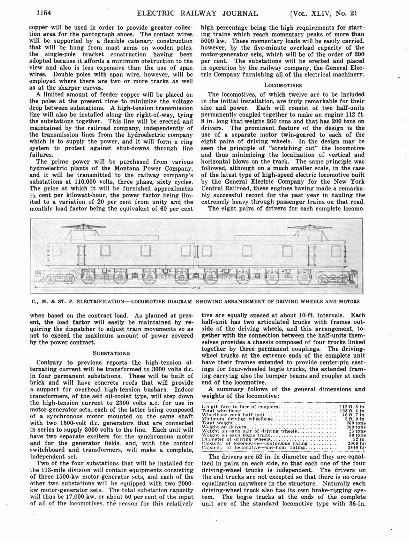
The locomotives, of which twelve are to be includedin the initial installation, are trul~r remarkable for theirsize and power. Each will consist of two half-unitspermanently coupled together to make an engine 112 ft.8 in. long that weighs 260 tons and that has 200 tons ondrivers. The prominent feature of the design is theuse of a separate motor twin-geared to each of theeight pairs of driving wheels. In the design may beseen the principle of "stretching out" the locomotiveand thus nlinimizing the localization of vertical andhorizontal blows on the track. The same principle wasfollowed, although on a much smaller scale, in the caseof the latest type of high-speed electric locomotive builtby the General Electric Company for the New YorkCentral Railroad, these engines having made a remarkably successful record for the past year in hauling theextremely heavy through passenger trains on that road.
The eight pairs of drivers for each complete locomo-
C., M. & ST. P. ELECTRIFICATION-LOCOMOTIVE DIAGRAM SHOWING ARRANGEMENT OF DRIVING WHEELS AND MOTORS
The drivers are 52 in. in diameter and they are equalized in pairs on each side, so that each one of the fourdriving-wheel trucks is independent. The drivers onthe end trucks are not excepted so that there is no crossequalization anywhere in the structure. Naturally eachdriving-wheel truck also has its own brake-rigging system. The bogie trucks at the ends of th,e completeu~it are of the standard locomotive type with 36-in.
tive are equally spaced at about 10-ft. intervals. Eachhalf-unit has two articulated trucks with frames outside of the driving wheels, and this arrangement, together with the connection between the half-units themselves provides a chassis composed of four trucks linkedtogether by three permanent couplings. The drivingwheel trucks at the extreme ends of the complete unithave their frames extended to provide center-pin castings for four-wheeled bogie trucks, the extended framing carrying also the bumper beams and coupler at eachend of the locomotive.
A summary follows of the general dimensions andweights of the locomotive:
when based on the contract load. As planned at present, the load factor will easily be maintained by requiring the dispatcher to adjust train movements so asnot to exceed the maximum amount of power coveredby th~e power contract.
SUBSTATIONS
Contrary to previous reports the high-tension alternating current will be transformed to 3000 volts d.c.in four permanent substations. These will be built ofbrick and will have concrete roofs that will providea support for overhead high-tension busbars. Indoortransformers, of the self oil-cooled type, will step downthe high-tension current to 2300 volts a.c. for use inmotor-generator sets, each of the latter being composedof a synchronous motor mounted on the same shaftwith two 1500-volt d.c. generators that are connectedin series to supply 3000 volts to the line. Each unit willhave two separate exciters for the synchronous motorand for the generator fields, and, with the controlswitchboard and transformers, will make a complete,independent set.
Two of the four substations that will be installed forthe 113-mile division will contain equiprnents consistingof three 1500-kw motor-generator sets, and each of theother two substations will be equipped with two 2000kw motor-generator set~. The total substation capacitywill thus be 17,000 kw, or about 50 per cent of the inputof all of the locomotives, the reason for this relatively
L~ngth face to faee of couplers .Total \vheelba::;e " .\\"heell.u.uoJe each half unit .AIinhllunl drivIng wheelbase .Tot~ll ,veiKht " ."-eig-ht 011 d ..iv~rs " , .\\~eight un ()aeh pail" of driving wheels .\Veight on each bogie h·uck "" .. " .I>inrnetel' of drivinK wheels " " .Capacity of locomotive-continuous rating"" .Capacity of 10COlllotive-one-hour rating." .
112 ft. 8 in.103 ft. 4 In.
-16 ft. 7 in.a ft. 0 in.260 ton~
200 ton825 ton830 ton~
52 in.3000 hp3440 hI'

NOVEMBER 21, 1914) ELECTRIC RAILWAY JOURNAL 1155
Electric Railway Graphics at A. I. E. E.Meeting .
been in charge of C. A. Goodnow, assistant to the president, Chicago, Milwaukee & St. Paul Railroad, and R.Beeuwkes, electrical engineer, and the work of construction that is soon to commence will be under their direction. In general, all of the erection will be done by therailroad company including the installation of the overhead lines, the construction of the substations, and thepreliminary operation during the future period oftransition from the use of steam to that of electricity.
Graphical Methods of Plotting Velocity-Time and DistanceTime Curves Were Considered at Last Week's Meeting
At the regular monthly meeting of the American Institute of Electrical Engineers, held in New York onNov. 13, part of the time was devoted to the presentationand discussion of a brief paper on CIA Graphic Methodfor Speed-Time and Distance-Time Curves," by E. C.Woodruff, of the electrical engineering faculty, Pennsylvania State College. This paper appears in theNovember issue of the A. I. E. E. Proceedings. Thepaper was discussed by C. O. Mailloux, N. W. Storer,Max von Recklinghausen, F. Castiglioni, and others.The general trend of the discussion indicated that the
method outlined by the author was ingenious but that ithad been used before substantially in the same form.The speakers emphasized the importance of graphicalmethods when many calculations are to be made. Mr.Mailloux described the methods which he had developedfor applying the integraph, a special form of planimeterwhich traces an integral curve, to electric railway problem solution. The limitations of graphical methods inregard to accuracy were referred to in the discussion,e,specially in methods involving an accumulation of errors as the one just presented does.
Professor Woodruff's method of plotting time-speed,or as Mr. Mailloux prefers "velocity-time," curves isexplained and illustrated briefly below:
In Fig. 1 are shown the curves which are desired;that is velocity-time and distance-time curves.
The velocity-time curve consists of two parts; astraight line from V = 0, t = 0 to Vltl where startingresistance has all been cut out, and a curved line fromV
lt
1onward as current is cut down by increasing
counter-emf.The straight-line part of the curve is calculated by
assuming starting current per motor and reading fromthe traction-current curve furnished by the motor manufacturer or experimentally determined, the traction
00....&.J&.J
00 Li..
00
00
00
00
00
403020SE.CONDS
10
RAILWAY GRAPHICS-FIG. 1
~v7V
V6
/ --- .....- ,.,.,..,.
~~~,.-.
rr~~~5
1...&'" ~
_~I ~~~ I~ [/
~" . ~ k~(V4f
---~ V,.~/····~"V " VJ~t, -~~V ~
) \)'f7 1V V
I Vv V I
I~
V .......KfO,.t,)IVo
o
20
~
:t
X-X
10
~o
wheels on 6-ft. centers. Each one will transmit a 30-tonload to the truck wheels for guiding purposes, the truckcenter pin being 13 ft. 5 in. ahead of the nearest drivingaxle.
The cab extends practically the full length of thelocomotive, the space between the two half-units beingminimized to provide easy passageway from one endof the locomotive to the other. The height of the cabroof is only 13 ft. 10 in. above the rail exclusive of thehousings for the ventilators, but the pantograph basesextend about 5 ft. above this owing to the great heightof the trolley wire, which will be maintained at an elevation of about 24 ft. above the rail. The cab for· eachhalf-unit will be supported at two points, one permittingrotation and the other a sliding movement so that thecl\assis can weave about in accordance with the requirements of the track but without affecting the cab.
MOTORS AND CONTROL
The eight motors for the complete locomotive will beof the General Electric No. 253-A type, and each willhave a continuous rating of 375 hp and a one-hourrating of 430 hp. This will give the locomotive a continuous rating of 3000 hp and an hourly rating of 3440hp. The drawbar pull effective for starting trains willapproximate 80,000 lb. As previously mentioned themotors will be twin-geared to the driving axles, that isto say, each armature shaft will carry a pinion on eachend, and it is only in the matter of gear ratio that thepassenger locomotives will differ from those used forhauling freight.
The motors will. be insulated for 8000 volts, but theywill be permanently connected in pairs in series so thatthe voltage across each one will be 1500 when the locomotive is operating in full parallel on the 3000-volttrolley. The control will provitie three running positionswith the four pairs of motors connected in series, seriesparallel or full-parallel, but the control system will include the novelty (for this country) of using regenerative braking control for holding trains on down grades.This will provide also for regenerative return of energyto the trolley wire on long down grades 80 that thepresence of a train going down a mountain grade willbe of assistance to another train coming up. This obviously will improve the load factor of the electrifieddivision to a marked degree.
The motor equipment will enable locomotives infreight service to pull 2500-ton trains up 1 per centgrades at a speed of 16 m.p.h., or, when two locomotives are used on a train, will provide power enoughto pull ·2500 tons up a 2-per cent grade. However, theplan of operation includes the general use of a locomotive at each end of trains on ascending grades, therebeing one 2 per cent grade 20 miles long and two 1 percent grades approximately 35 miles long on the electrified section. On descending grades only the locomotive at the head end will do the regenerative braking.The locomotives in passenger service will be called uponto haul trailing loads of 800 tons at a speed of 60 m.p.h.on the level.
Collection of the large drafts of current (rangingfrom 1500 amp to 2000 amp at 3000 volts) that will berequired for the service at times will be effected throughthe use of two pantographs of the "pan" type on eachcomplete locomotive. As a provision against the possibility of injurious arcing, however, and to supply anample factor of surplus capacity the previously mentioned use of a double trolley wire was considered desirable. This secures flexibility and gives a greaterarea of collection, the maximum draft of current perpantograph contact being thus reduced to the order of500 amp.
All of the plans for the electrification project have