Embed Size (px)
Citation preview

1 | P a g e
University of Central Florida Main Campus
Electric
Service and Meter Installations Requirements
Issued – January 26th, 2017

2 | P a g e
Table of Contents 1. GENERAL INFORMATION ...................................................................................................................... 3
2. DEFINITIONS .......................................................................................................................................... 3
3. TYPE AND CHARACTER OF SERVICE ...................................................................................................... 4
4. Typical Requirements............................................................................................................................ 5
5. Meter Location ...................................................................................................................................... 6
6. Current Transformer Installations ........................................................................................................ 6
7. Plan Review and Coordination with UCF UES ....................................................................................... 7
ELEC – FIGURE 00: GENERAL NOTES RELATED TO ELECTRIC SERVICE
ELEC – FIGURE 01: ELECTRIC SERVICE RESPONSIBILITY TABLE
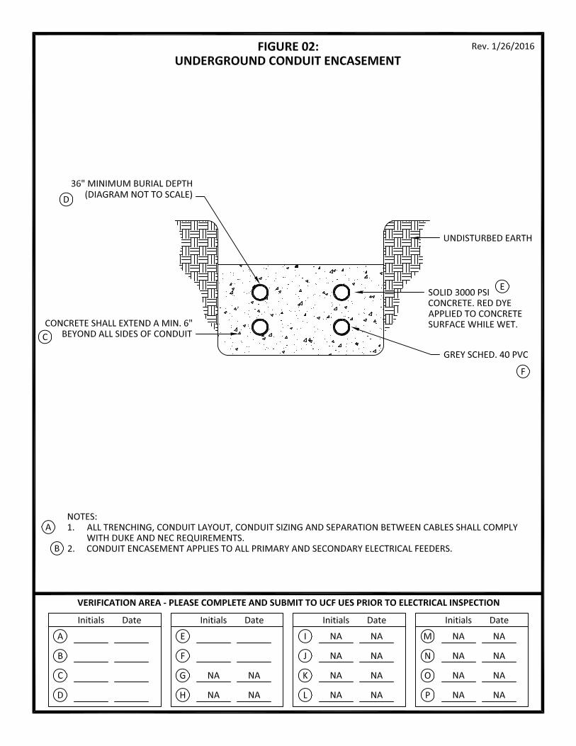
ELEC – FIGURE 02: UNDERGROUND CONDUIT ENCASEMENT
ELEC – FIGURE 03A: POST-MOUNTED METER DETAIL W/ CTS IN XFMR
ELEC – FIGURE 03B: BUILDING-MOUNTED METER, SELF-CONTAINED METER OR METER W/ CTS IN BLDG
ELEC – FIGURE 03C: BUILDING-MOUNTED METER W/ CT CABINET
ELEC – FIGURE 04A: METER BASE FORM 1S WIRING DIAGRAM
ELEC – FIGURE 04B: METER BASE FORM 2S WIRING DIAGRAM
ELEC – FIGURE 04C: METER BASE FORM 9S WIRING DIAGRAM
ELEC – FIGURE 04D: METER BASE FORM 16S WIRING DIAGRAM
ELEC – FIGURE 05: SELF-CONTAINED METER BASE LINE & LOAD WIRING CONFIGURATIONS (FORM 1S,
2S, 9S, 16S)"
ELEC – FIGURE 06: CT WIRING AND CONDUIT SIZING TABLE
ELEC – FIGURE 07: CT CABINET SIZING CHART
ELEC – FIGURE 08: CT CABINET WIRING AND MOUNTING DIAGRAM
ELEC – FIGURE 09: CURRENT TRANSFORMER (CT) REQUIREMENTS
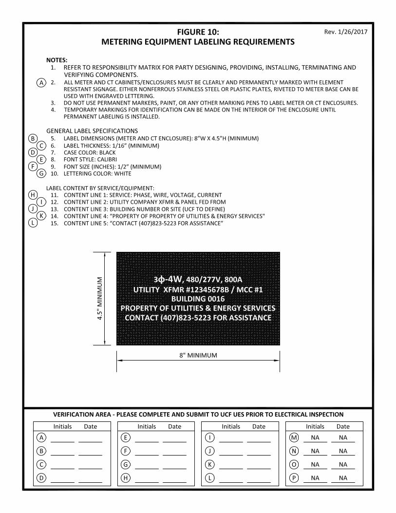
ELEC – FIGURE 10: METERING EQUIPMENT LABELING REQUIREMENTS

3 | P a g e
1. GENERAL INFORMATION 1.1. Duke Energy maintains the Main Campus Primary Loop and associated step down transformers;
therefore, Duke Energy’s standards and requirements shall be considered the minimum
standard for all new and existing service modifications. These UCF Construction Standards are
intended to identify any items that must exceed Duke’s minimum requirements, as well as any
minimum Code requirements.
1.2. Electric meters and sub-meters are utilized for utility billing, savings calculations, demand
profiling, and performance monitoring. Essential to these functions are an accurate, properly
selected and installed system. The following information pertains mainly to “low voltage”
services at 600V and under, unless otherwise specified.
1.3. For services greater than 600V, please contact UCF Utilities & Energy Services directly for
specific requirements.
1.4. Electric utility requirements such as conduit for primary conductors and concrete requirements
for pad-mounted transformers will still be dictated by Duke Energy’s minimum standards;
however, UCF has provided a few additional items through the included details
1.5. For ease of use, this section of the construction standards refers to multiple 8.5”x11” details or
Figures. These details are used to convey critical information to the designer, track the
designers progress and verify the contractor’s installation. These details or Figures will be
referenced below and are intended to be incorporated into the construction documents, by the
designer, after a detailed review for Code and design intent requirements.
2. DEFINITIONS 2.1. Low Voltage up to 600V (AC) 2.2. Medium Voltage 1kV – 35kV (AC) 2.3. High Voltage greater than 35kV (AC)
2.4. Main Distribution Panel Meter: Switchgear/Panel mounted meter covering complete main
service to the entire facility 2.5. Billing Electric Meter: Main exterior mount revenue/billing meter for each main service to a
facility 2.6. Billing Electric Sub-Meter: Meter installed on a portion of the main facilities electrical
distribution, downstream of the main facility meter; primarily used to measure electric consumption for billing purposes.
2.7. BAS Electric Meter: Meter installed main service or on a portion of the main facilities electrical distribution, downstream of the main facility meter; primarily monitored through BAS for specific loads related to lighting, chilled water equipment and plug-load circuits.
2.8. MCC (Motor Control Center): Assembly of one or more enclosed sections having a common power bus and containing motor control units.
2.9. Switch Gear: Combination of electrical disconnect switches, fuses or circuit breakers used to control, protect and isolate electrical equipment
2.10. Utility Transformer: Any pole-mount or pad-mount distribution transformers providing the final voltage transformation in the electric power distribution system, stepping down the voltage used in the distribution lines to the level used by the customer.

4 | P a g e
2.11. CT (Current Transformer): Also known as instrument transformer, are used to reduce the primary current accurately proportional to the current in the circuit, allowing for convenient connections to measuring and sensing equipment.
2.12. PT (Potential Transformer): Voltage transformers (VT) (also called potential transformers (PT)) are a type of instrument transformer, used for metering and protection in high-voltage circuits or phasor phase shift isolation. They are designed to present negligible load to the supply being measured and to have an accurate voltage ratio to enable accurate metering.
3. TYPE AND CHARACTER OF SERVICE 3.1. Services shall be underground. Overhead services are not permitted.
3.2. Standard voltages shall be 120/240, 120/208 and 277/480.
3.3. All new services shall be 277/480V 3-Phase 4-Wire, with the following exceptions:
3.3.1. 120/208V 3-Phase is acceptable if service is 400A or less at specified voltage.
3.3.2. 120/240V 1-Phase is acceptable for temporary services, unoccupied structures and
auxiliary equipment if service is 400A or less at specified voltage. e.g. Construction trailer,
Illuminated signs or irrigation controllers.
3.4. Use the table below to locate the service type being provided. Then refer to the Figures
indicated. These Figures are intended to be incorporated into the construction documents, as
referenced in the section above.
Circuit Voltage Service Size
(Amps) Current Connections
Figures to Include
2-wire, 1-phase
120 Up to 400A Self-contained Figure #00, 01, 02, 03B, 04A, 05, 10
3-wire, 1-phase
120/240 Up to 400A Self-contained Figure #00, 01, 02, 03B, 04B, 05, 10
Over 400A With CTs
Figure #00, 01, 02, 03A or 03B or 03C, 04C, 06, 07, 08, 09, 10
3-wire network
120/208 Up to 400A Self-contained Figure #00, 01, 02, 03B, 05, 10
Over 400A With CTs
Figure #00, 01, 02, 03A or 03B or 03C, 04C, 06, 07, 08, 09, 10
4-wire wye
120/208 OR
277/480 Up to 400A Self-contained
Figure #00, 01, 02, 03B, 04D, 05, 10
Over 400A With CTs
Figure #00, 01, 02, 03A or 03B or 03C, 04C, 06, 07, 08, 09, 10
Over 600V
Coordinate directly w/ UCF UES & Duke
*For services over 200A, a meter with CTs may be used in lieu of a self-contained meter.

5 | P a g e
3.5. Temporary Service
3.5.1. This is a service that will be temporarily installed and energized for short term use
involving project/contracted work services until project completion. Service is not utilized
in any way as a “permanent” facility service and will be coordinated for disconnection and
removal at the completion of the project. (Example: Temporary construction trailer or site
power for project work)
3.5.2. Temporary services to construction trailers or site power for projects that are building
expansions must not be serviced off an existing facilities circuit(s). All temporary
connections must be direct from the utility company transformer for site power or
construction trailers. If this is not feasible, a generator must be utilized for temporary
power during construction.
3.5.3. Facilities under construction, that are connected to any existing facility as an “expansion”
or added space, must have all construction related circuits separately “sub-metered” for
billing purposes. Sub-metered use will be subtracted from the original building’s main
service meter. It is the responsibility of the project/contractor to fund any power
consumption directly related to the project, even in existing building expansions.
3.5.4. Temporary services shall follow the same requirements outlined in these construction
standards.
3.6. Permanent Service
3.6.1. Permanent service conductors installed for purpose of supplying main power feed to
newly renovated or constructed facility, site, or structure.
3.6.2. Permanent service, upon final approval for Certificate of Occupancy, will transfer
responsibility of service from the project or contractor to the final end customer.
3.6.3. Separate physical structures must have separate utility services (distributions) originating
from the Utility Company transformer. At no point should any facility be fed from an
individual circuit downstream of a main service on another facility, causing a condition for
sub-metered loads and split billing.
4. TYPICAL REQUIREMENTS 4.1. Electrical rooms must be located along an exterior main wall with the electric meter installed
on the exterior of the building.
4.2. If the electrical room, by design, cannot be located along an exterior wall, and distance is
greater than 50 linear feet from meter enclosure to current transformers, then the meter must
be installed in one of two ways:
4.2.1. Exterior Wall Mount (Meter & CT Enclosure)
4.2.1.1. Primary conductors from utility transformer to site must be routed through a
wall-mounted CT Cabinet.
4.2.1.2. A primary disconnect must follow the CT cabinet before entering main electrical
room.
4.2.2. Exterior Concrete Post Mount (Meter & CT Enclosure)
6 | P a g e
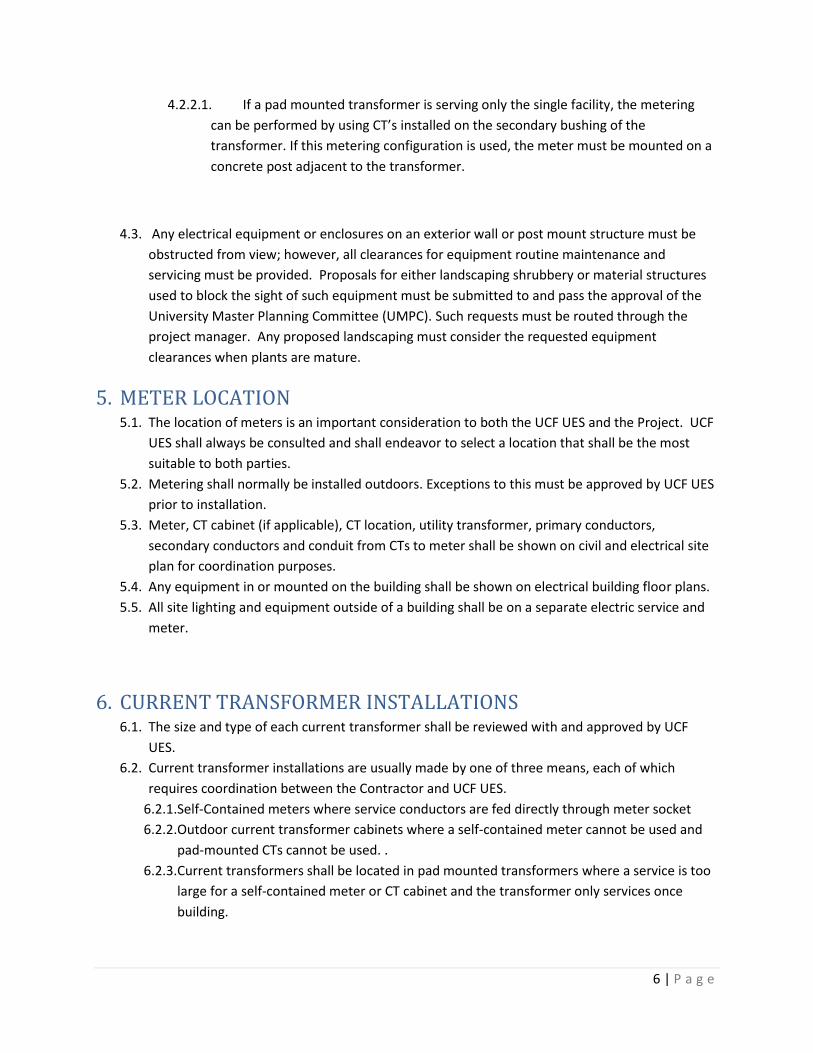
4.2.2.1. If a pad mounted transformer is serving only the single facility, the metering
can be performed by using CT’s installed on the secondary bushing of the
transformer. If this metering configuration is used, the meter must be mounted on a
concrete post adjacent to the transformer.
4.3. Any electrical equipment or enclosures on an exterior wall or post mount structure must be
obstructed from view; however, all clearances for equipment routine maintenance and
servicing must be provided. Proposals for either landscaping shrubbery or material structures
used to block the sight of such equipment must be submitted to and pass the approval of the
University Master Planning Committee (UMPC). Such requests must be routed through the
project manager. Any proposed landscaping must consider the requested equipment
clearances when plants are mature.
5. METER LOCATION 5.1. The location of meters is an important consideration to both the UCF UES and the Project. UCF
UES shall always be consulted and shall endeavor to select a location that shall be the most
suitable to both parties.
5.2. Metering shall normally be installed outdoors. Exceptions to this must be approved by UCF UES
prior to installation.
5.3. Meter, CT cabinet (if applicable), CT location, utility transformer, primary conductors,
secondary conductors and conduit from CTs to meter shall be shown on civil and electrical site
plan for coordination purposes.
5.4. Any equipment in or mounted on the building shall be shown on electrical building floor plans.
5.5. All site lighting and equipment outside of a building shall be on a separate electric service and
meter.
6. CURRENT TRANSFORMER INSTALLATIONS 6.1. The size and type of each current transformer shall be reviewed with and approved by UCF
UES.
6.2. Current transformer installations are usually made by one of three means, each of which
requires coordination between the Contractor and UCF UES.
6.2.1. Self-Contained meters where service conductors are fed directly through meter socket
6.2.2. Outdoor current transformer cabinets where a self-contained meter cannot be used and
pad-mounted CTs cannot be used. .
6.2.3. Current transformers shall be located in pad mounted transformers where a service is too
large for a self-contained meter or CT cabinet and the transformer only services once
building.

7 | P a g e
7. PLAN REVIEW AND COORDINATION WITH UCF UES 7.1. Coordination of service and metering requirements with UCF UES is important for the success
of the project. UCF UES will arrange joint meetings with UCF UES and Duke Energy at each
phase of project.
7.2. At the 50% Construction Document Phase the following shall be shown on plans and reviewed
with UCF UES:
7.2.1. Proposed location of pad-mounted transformer
7.2.2. Proposed routing of primary conduit and conductors to new transformer.
7.2.3. Proposed routing of service entrance conduits/conductors.
7.2.4. Proposed location of meter.
7.2.5. Proposed metering arrangement.
7.2.6. Designer shall submit all included Figures identified by UCF for the service type. Designer
shall identify any aspects of the Figure that cannot or will not be provided.
7.3. At the 100% Construction Document Phase the following shall be shown on plans and reviewed
with UCF UES:
7.3.1. Location of pad mounted transformer.
7.3.1.1. Transformer pad details coordinated with Duke Energy
7.3.2. Routing of primary to new transformer.
7.3.2.1. Primary Conduit Sizing.
7.3.2.2. Primary Conduit Installation Details.
7.3.3. Routing of service entrance conduits/conductors.
7.3.3.1. Sizes of conductors and conduits.
7.3.3.2. Load sizing calculations
7.3.4. Location of meter enclosure.
7.3.4.1. Metering arrangement including:
7.3.4.2. Specific models and specifications of CT’s to be utilized if applicable.
7.3.4.3. Mounting method for CT’s as applicable.
7.3.4.4. Size and specifications for CT cabinet as applicable.
7.3.4.5. Routing and size of conduits and wiring interconnecting CT’s with meter
enclosure.
7.3.4.6. Specific models and specification of meter enclosure.
7.3.5. Designer shall submit all included Figures identified by UCF for the service type. Designer
shall identify any aspects of the Figure that cannot or will not be provided. All requested
Figures shall be submitted to UCF UES, through UCF’s project manager, at the 50% and
100% construction document submission.