Embed Size (px)
Citation preview
Return to Session
ELECTRICAL AND THERMAL DESIGN OF UMBILICAL CABLE
Derek SHACKLETON, Oceaneering Multiflex UK, (Scotland), [email protected] ABIB, Marine Production Systems do Brasil, (Brazil), [email protected] BALENA, Marine Production Systems do Brasil, (Brazil), [email protected]
ABSTRACTThe main purpose of this technical paper is to analyze the various designs available for a Submarine Electro Hydraulic Umbilical, composed of power conductors, signal/control cables, steel tubes, thermoplastic hoses and/or optical cables, in order to reduce the options to the final project definition, considering the magnetic and thermal limitations of the components.The circulating current at the power cores may cause a heating, higher than the operational temperature limit of the others components (thermoplastic hoses) and an induced voltage at the signal cables. The thermal and electrical analyses are performed to ensure that the cable design comply with the specification and is suitable for its operation conditions. Finite element software for electromagnetic and thermal simulation is used and the analysis is based on the two-dimensional geometry of the object under evaluation and its materials physical properties. The umbilical cable is suitable for static and dynamic application up to 3000 meters water depths and a service life of 25 years. The cable may be connected between platforms, wells and landfallReal data for the induced voltage at signal cables under investigation are presented, discussed and also comparedwith theoretical value.This paper also describes the methodology applied in the magnetic and thermal analysis.
KEYWORDSSubmarine Electro Hydraulic Umbilical,Electrical Analysis, Thermal Analysis.
INTRODUCTIONA subsea umbilical cable can be composed of steel tubes, hydraulic hoses, optical, power and signal cables.It may be used to power submerged pumps to overcome ultra-deep water pressures, low reservoir pressure, long offsets connections from a central platform, high produced fluid viscosities, extend the life of mature fields or accelerate production on new fields. Adding power cables to an umbilical can create some difficulties: temperature increase, electrical interference, limits to the length of the cable (splices).Power cables can generate interference in signal cables due to its circulating current. Different cables are designed in order to minimize the effect of the induced voltages and guarantee the applicability of the product during its operational service life from an electromagnetic and thermal point of view.
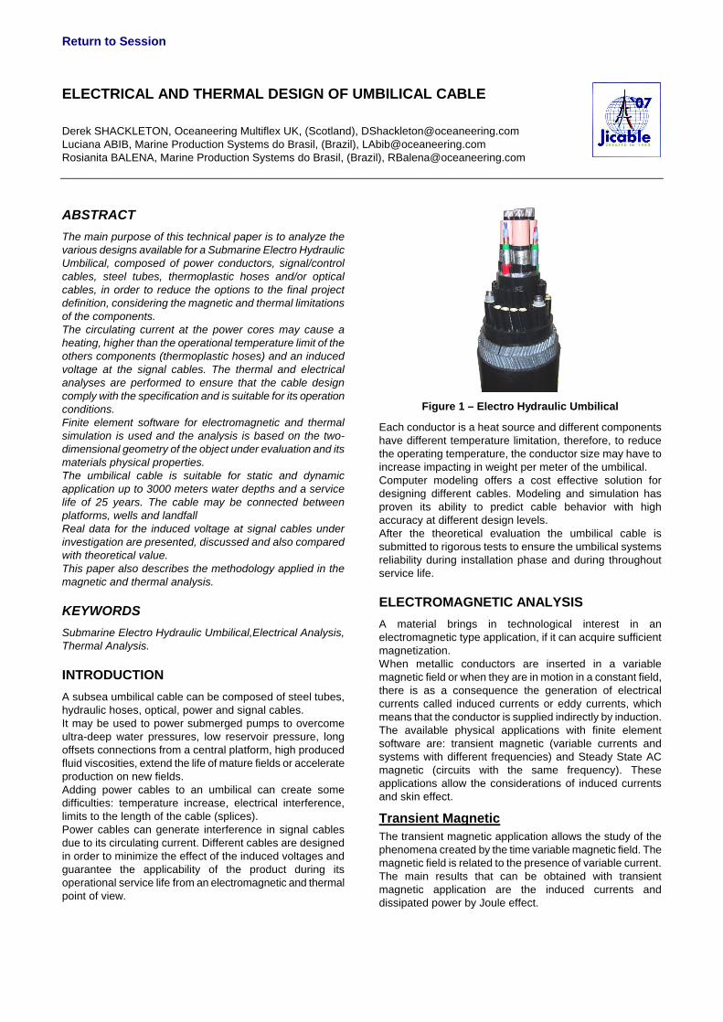
Figure 1 – Electro Hydraulic Umbilical
Each conductor is a heat source and different components have different temperature limitation, therefore, to reduce the operating temperature, the conductor size may have to increase impacting in weight per meter of the umbilical. Computer modeling offers a cost effective solution for designing different cables. Modeling and simulation has proven its ability to predict cable behavior with high accuracy at different design levels.After the theoretical evaluation the umbilical cable is submitted to rigorous tests to ensure the umbilical systems reliability during installation phase and during throughout service life.
ELECTROMAGNETIC ANALYSISA material brings in technological interest in an electromagnetic type application, if it can acquire sufficient magnetization.When metallic conductors are inserted in a variable magnetic field or when they are in motion in a constant field,there is as a consequence the generation of electrical currents called induced currents or eddy currents, which means that the conductor is supplied indirectly by induction.The available physical applications with finite element software are: transient magnetic (variable currents and systems with different frequencies) and Steady State AC magnetic (circuits with the same frequency). These applications allow the considerations of induced currents and skin effect.
Transient MagneticThe transient magnetic application allows the study of the phenomena created by the time variable magnetic field. The magnetic field is related to the presence of variable current. The main results that can be obtained with transient magnetic application are the induced currents and dissipated power by Joule effect.
Return to Session
Steady State AC MagneticThe Steady State AC magnetic application allows the study of devices in the harmonic state (sinusoidal steady state) for a given frequency. Maxwell’s equations consider all physical quantities are sinusoidal time-varying for a given frequency. The magnetic field is connected by the presence of the time varying electric currents, compulsory sinusoidal. This application takes into account the currents induced in the conducting regions (eddy currents). It also considers the skin effect and the proximity effects.
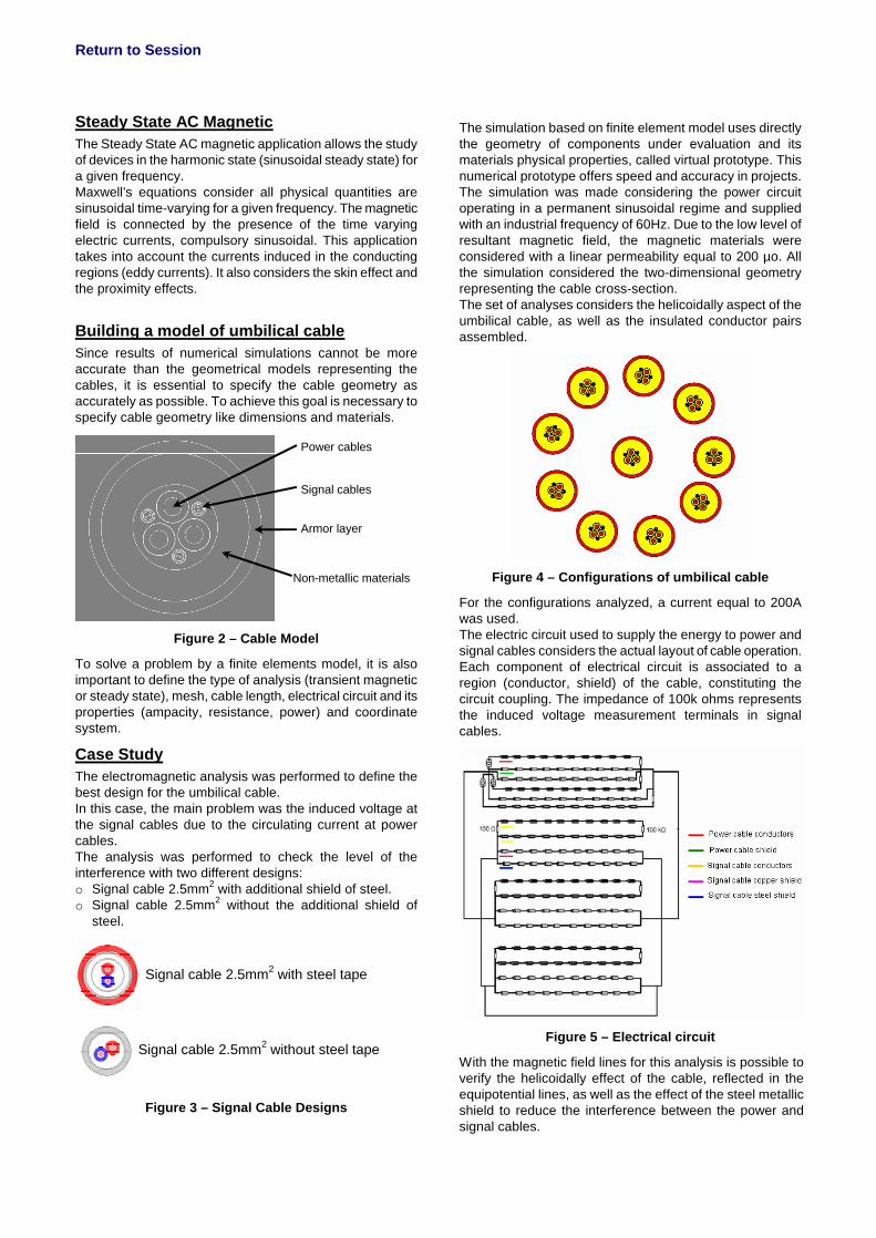
Building a model of umbilical cableSince results of numerical simulations cannot be more accurate than the geometrical models representing the cables, it is essential to specify the cable geometry as accurately as possible. To achieve this goal is necessary to specify cable geometry like dimensions and materials.
Power cables
Signal cables
Armor layer
Non-metallic materials
Figure 2 – Cable Model
To solve a problem by a finite elements model, it is also important to define the type of analysis (transient magnetic or steady state), mesh, cable length, electrical circuit and its properties (ampacity, resistance, power) and coordinate system.
Case StudyThe electromagnetic analysis was performed to define the best design for the umbilical cable. In this case, the main problem was the induced voltage at the signal cables due to the circulating current at power cables. The analysis was performed to check the level of the interference with two different designs:o Signal cable 2.5mm2 with additional shield of steel.o Signal cable 2.5mm2 without the additional shield of
steel.
Signal cable 2.5mm2 with steel tape
Signal cable 2.5mm2 without steel tape
Figure 3 – Signal Cable Designs
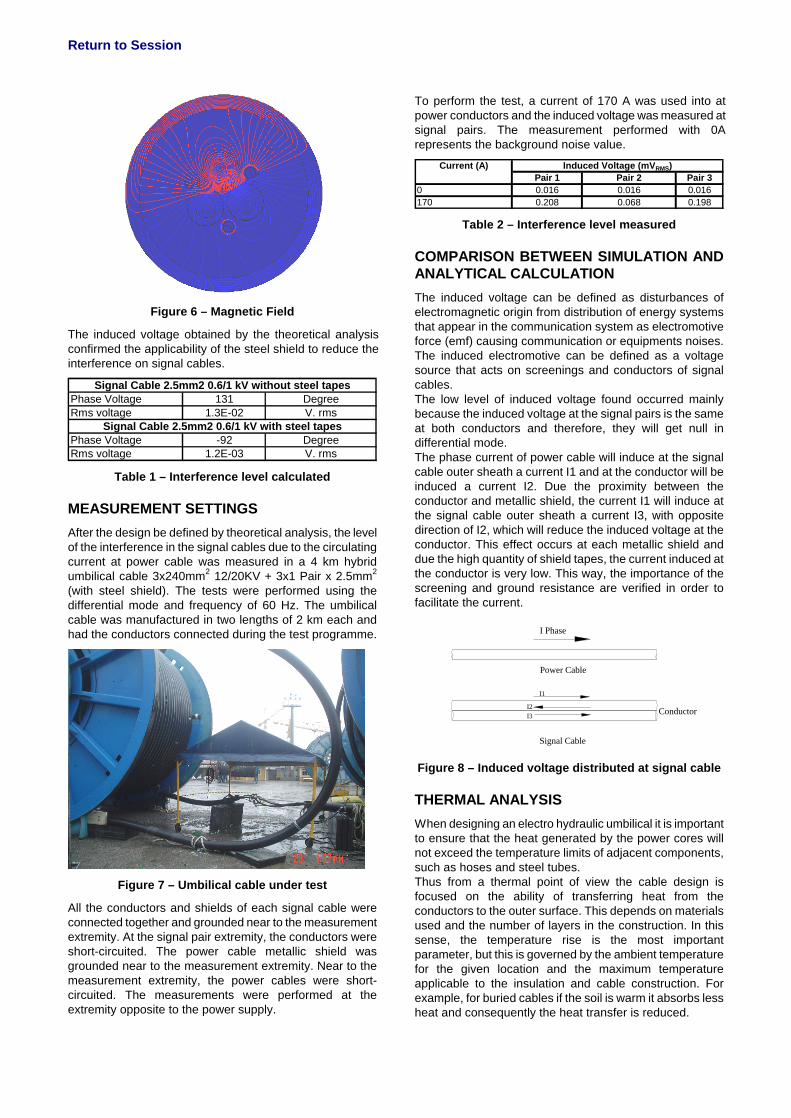
The simulation based on finite element model uses directly the geometry of components under evaluation and its materials physical properties, called virtual prototype. This numerical prototype offers speed and accuracy in projects. The simulation was made considering the power circuit operating in a permanent sinusoidal regime and supplied with an industrial frequency of 60Hz. Due to the low level of resultant magnetic field, the magnetic materials were considered with a linear permeability equal to 200 µo. All the simulation considered the two-dimensional geometry representing the cable cross-section.The set of analyses considers the helicoidally aspect of the umbilical cable, as well as the insulated conductor pairs assembled.
Figure 4 – Configurations of umbilical cable
For the configurations analyzed, a current equal to 200Awas used. The electric circuit used to supply the energy to power and signal cables considers the actual layout of cable operation. Each component of electrical circuit is associated to a region (conductor, shield) of the cable, constituting the circuit coupling. The impedance of 100k ohms represents the induced voltage measurement terminals in signal cables.
Figure 5 – Electrical circuit
With the magnetic field lines for this analysis is possible to verify the helicoidally effect of the cable, reflected in the equipotential lines, as well as the effect of the steel metallic shield to reduce the interference between the power and signal cables.
Return to Session
Figure 6 – Magnetic Field
The induced voltage obtained by the theoretical analysis confirmed the applicability of the steel shield to reduce the interference on signal cables.
Phase Voltage 131 DegreeRms voltage 1.3E-02 V. rms
Phase Voltage -92 DegreeRms voltage 1.2E-03 V. rms
Signal Cable 2.5mm2 0.6/1 kV without steel tapes
Signal Cable 2.5mm2 0.6/1 kV with steel tapes
Table 1 – Interference level calculated
MEASUREMENT SETTINGSAfter the design be defined by theoretical analysis, the level of the interference in the signal cables due to the circulating current at power cable was measured in a 4 km hybrid umbilical cable 3x240mm2 12/20KV + 3x1 Pair x 2.5mm2
(with steel shield). The tests were performed using the differential mode and frequency of 60 Hz. The umbilical cable was manufactured in two lengths of 2 km each and had the conductors connected during the test programme.
Figure 7 – Umbilical cable under test
All the conductors and shields of each signal cable wereconnected together and grounded near to the measurement extremity. At the signal pair extremity, the conductors were short-circuited. The power cable metallic shield was grounded near to the measurement extremity. Near to the measurement extremity, the power cables were short-circuited. The measurements were performed at the extremity opposite to the power supply.
To perform the test, a current of 170 A was used into at power conductors and the induced voltage was measured at signal pairs. The measurement performed with 0A represents the background noise value.
Pair 1 Pair 2 Pair 30 0.016 0.016 0.016170 0.208 0.068 0.198
Current (A) Induced Voltage (mVRMS)
Table 2 – Interference level measured
COMPARISON BETWEEN SIMULATION AND ANALYTICAL CALCULATIONThe induced voltage can be defined as disturbances of electromagnetic origin from distribution of energy systems that appear in the communication system as electromotive force (emf) causing communication or equipments noises. The induced electromotive can be defined as a voltage source that acts on screenings and conductors of signal cables.The low level of induced voltage found occurred mainly because the induced voltage at the signal pairs is the same at both conductors and therefore, they will get null in differential mode.The phase current of power cable will induce at the signal cable outer sheath a current I1 and at the conductor will be induced a current I2. Due the proximity between the conductor and metallic shield, the current I1 will induce at the signal cable outer sheath a current I3, with opposite direction of I2, which will reduce the induced voltage at the conductor. This effect occurs at each metallic shield and due the high quantity of shield tapes, the current induced at the conductor is very low. This way, the importance of the screening and ground resistance are verified in order to facilitate the current.
I Phase
Power Cable
Signal Cable
I1
I2I3 Conductor
Figure 8 – Induced voltage distributed at signal cable
THERMAL ANALYSISWhen designing an electro hydraulic umbilical it is important to ensure that the heat generated by the power cores will not exceed the temperature limits of adjacent components, such as hoses and steel tubes. Thus from a thermal point of view the cable design is focused on the ability of transferring heat from the conductors to the outer surface. This depends on materials used and the number of layers in the construction. In this sense, the temperature rise is the most important parameter, but this is governed by the ambient temperature for the given location and the maximum temperature applicable to the insulation and cable construction. For example, for buried cables if the soil is warm it absorbs less heat and consequently the heat transfer is reduced.
Return to Session
When the conductor is energized, heat is generated within the cable due to losses of conductor, dielectric, insulation and metallic screens which define thermal resistances that control heat dissipation.A system with heat sources and thermal exchanges is in a non-equilibrium state. This thermal exchange can be achieved by:
o Thermal conduction: occurs without transport of matter, the heat transfer is determined by the existence of a temperature gradient. Only this type of heat transfer is possible in solid bodies.
o Thermal convection: presupposes heat transfer on the surface that separates a solid body from a fluid, or inside a mixture of fluids. A macroscopic transport of matter is associated.
o Thermal radiation: a heated body emits energy through electromagnetic radiation.
For thermal analyses the same finite element software used for electromagnetic analyses is applied. The analyses performed have some limitations, such as two-dimensional behavior and direct modeling only of thermal conduction. The remaining thermal exchanges can only be modeledthrough boundary conditions. The components of umbilical cables are modeled as solid bodies whose thermal conductivity properties are known and a convection coefficient is imposed on outer sheath to simulate the thermal exchange with the surrounding environment. The basic relations of conduction heat transfer are the Fourier’s law [1] and the equation of heat conduction [2]:
Tdgrakrr ][−=ϕ [1]
qtTCdiv p =
∂∂
+ ρϕ )( r [2]
where:ϕr
heat flux density][k tensor of thermal conductivity (W/mK)
pCρ specific heat (J/m3K)q volume density of power (W/m3)
Transient and steady thermal states can be simulated, being steady thermal state the situation when the temperature field does not vary with respect to time. Therefore the equation to be solved will be simply:
qTdgrakdiv =− )][(r
[3]
The obtainable results in both applications are space distribution of temperature inside and on the boundary ofthe computation domain, characterized by the umbilical cable, and the thermal flux through the boundary surface.Thus, the definition of the finite element problem requires a computation domain and boundary conditions, i.e. to define the regions where the temperature field is studied and the values of the state variable on computation boundaries. For the umbilical cables analysed the study domain includes only solid parts of the modelled service. Three types of sources can be imposed: heat sources (q), heat flux density (ϕ
r) and temperature (T). These can be
uniform or space dependent and imposed on boundary lines to represent heat transfer effects.
In the application case presented here, the power resulting from circulating current on power conductors is the imposed heat source. Besides the components thermal properties and the heat sources the solver also needs spatial and temporal information about the initial temperature to set up conditions on first time step and begin the computation.
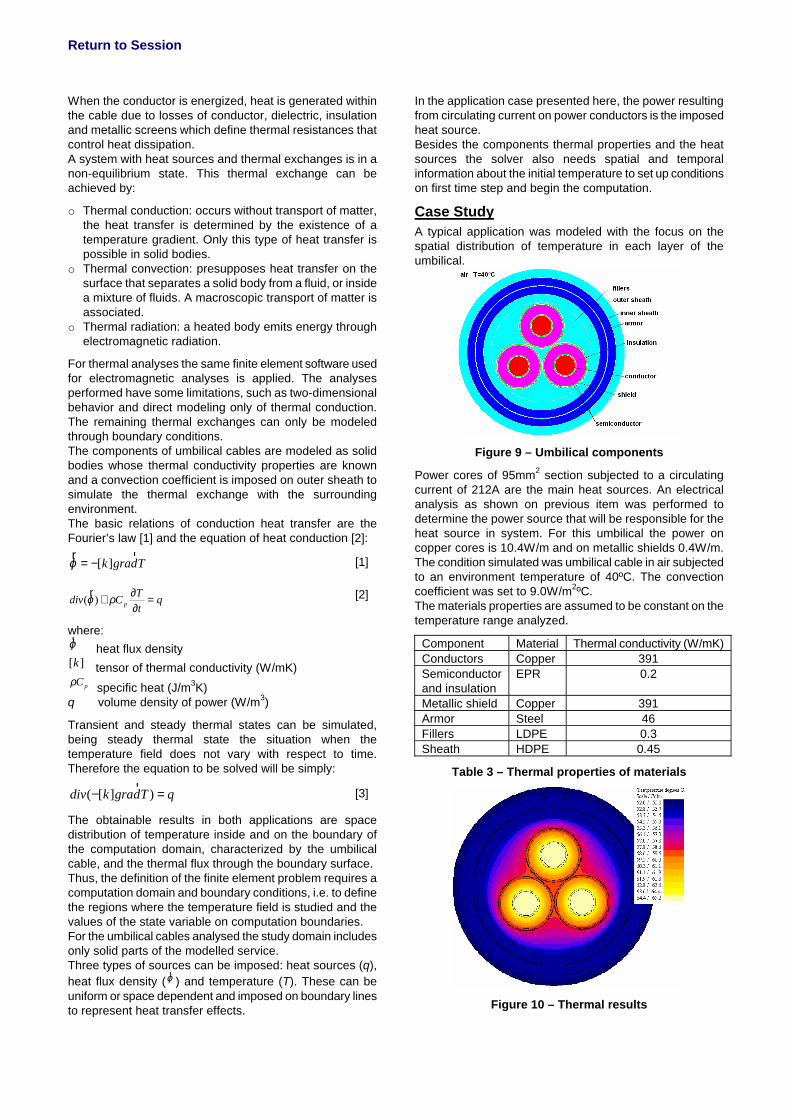
Case StudyA typical application was modeled with the focus on the spatial distribution of temperature in each layer of the umbilical.
Figure 9 – Umbilical components
Power cores of 95mm2 section subjected to a circulating current of 212A are the main heat sources. An electrical analysis as shown on previous item was performed to determine the power source that will be responsible for the heat source in system. For this umbilical the power on copper cores is 10.4W/m and on metallic shields 0.4W/m. The condition simulated was umbilical cable in air subjected to an environment temperature of 40ºC. The convection coefficient was set to 9.0W/m2ºC.The materials properties are assumed to be constant on the temperature range analyzed.
Component Material Thermal conductivity (W/mK)Conductors Copper 391Semiconductor and insulation
EPR 0.2
Metallic shield Copper 391Armor Steel 46Fillers LDPE 0.3Sheath HDPE 0.45
Table 3 – Thermal properties of materials
Figure 10 – Thermal results
Return to Session
Besides the condition in air, umbilicals can also be simulated inside the I-tube, in seawater or buried, the key difference being changes on boundary conditions such as the convection coefficient.
COMPARISON BETWEEN SIMULATION AND ANALYTICAL CALCULATIONThe analytical model used for this comparison was based on Standard IEC 60287 ([1] ; [2]). IEC 60287 covers medium-voltage and high-voltage cables, many different constructions, and many installation types. It is the predominant method used internationally.The maximum permissible current rating means the current that applied continuously until reaching steady state will produce the maximum allowable conductor temperature. This steady state is the only condition considered when calculating the maximum permissible continuous current rating. The permissible current rating is derived from the expression for the temperature rise above ambient temperature [1]:
5.0
4321211
4321d
)T)(TnR(1)TnR(1RT)TTn(T[0.5TW
++++++
+++−∆=
λλλθI [4]
where:
T1, T2, T3 and T4 are the thermal resistances (explained on Table 4)n number of conductors in a cableWd dielectric losses per unit length per phaseR alternating current resistance of conductor
θ∆ temperature rise above ambient temperature
1λ , 2λ ratio of total losses in metallic sheaths respectively to the total conductor losses.
Knowing the desired current, the conductor and thermal resistances and the cable losses it is possible to determine the conductor temperature.
Power LossesA power cable consists of several components, the most basic being the conductor and the insulation which can be seen in any power cable.There are four heat sources produced by losses: cable conductor, metallic sheath/screen, armoring and dielectric. The loss that occurs in the cable conductor is proportional to the conductor resistance and to the square of the circulating current. This loss normally represents the largest heat source in the cable.When the cable carries alternating currents, the conductor resistance increases due to the skin and proximity effects that are accounted for by the finite element software used, as discussed on previous section.The magnetic fields flowing in the conductors induce electromagnetic fields in the metallic screen which causes currents to flow in the screen and generate losses. There are two types of losses which occur as sheath eddy loss and the sheath circulating loss. The sheath circulating loss is reduced since the three cables are placed close together. However, the closer formation results in a greater eddy loss and also increases the mutual heating of the three cables.
When calculating current rating by analytical procedure, following Standard of IEC [1], these losses are also accounted for by means of loss factors and thermal resistances.
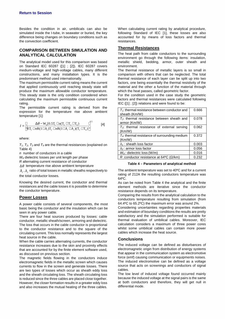
Thermal ResistancesThe heat path from cable conductors to the surrounding environment go through the following items: insulation, metallic shield, bedding, armor, outer sheath and environment.The thermal resistance of metallic layers is so small in comparison with others that can be neglected. The total thermal resistance of each layer can be split up into two factors, one being essentially the thermal resistivity of the material and the other a function of the material through which the heat passes, called geometric factor. For the condition used in the case study the geometric factors and thermal resistances were calculated following IEC ([1] ; [2]) relations and were found to be:
T1: thermal resistance between conductor and sheath (Km/W)
0.666
T2: thermal resistance between sheath and armor (Km/W)
0.078
T3: thermal resistance of external serving (Km/W)
0.062
T4: thermal resistance of surrounding medium (Km/W)
0.372
λ1 : sheath loss factor 0.003λ2 : armor loss factor 0.056Wd : dielectric loss (W/m) 0.016R :conductor resistance at 64ºC (Ω/km) 0.232
Table 4 – Parameters of analytical method
The ambient temperature was set to 40ºC and for a current rating of 212A the resulting conductors temperature was 64ºC.As can be noted from Table 4 the analytical and the finite element methods are iterative since the conductor resistance depends on its temperature. Comparing the results from the analytical calculation to the conductors temperature resulting from simulation (from 64.4ºC to 65.2ºC) the maximum error was around 2%. Considering uncertainties regarding properties materials and estimation of boundary conditions the results are pretty satisfactory and the simulation performed is suitable for thermal evaluation of umbilical cables. Moreover, IEC calculation considers a maximum of three power cores whilst some umbilical cables can contain more power cables which increase the heat source.
Conclusions The induced voltage can be defined as disturbances of electromagnetic origin from distribution of energy systems that appear in the communication system as electromotive force (emf) causing communication or equipments noises. The induced electromotive can be defined as a voltage source that acts on screenings and conductors of signal cables.The low level of induced voltage found occurred mainly because the induced voltage at the signal pairs is the same at both conductors and therefore, they will get null in differential mode.

Return to Session
The theoretical and the experimental test obtained resultswere satisfactory compared.The thermal results for a three-core umbilical cable were satisfactory compared to the available calculation based on IEC Standard. Some uncertainties still exist mainly regarding boundary conditions imposed to the model, which can affect substantially the results. Therefore, further work should be carried out including thermal measurements on field or at test benches in order to validate and calibrate some model assumptions.
REFERENCES
[1] IEC 60287-1-1 “Electric Cables Calculation of the current rating – Part 1”, 2001.
[2] IEC 60287-2-1 “Electric Cables Calculation of the current rating – Part 2”, 2001.
[3] D.G.A.K. Wijeratna et al.,2003. “Development of a Software Package for Calculating Current Rating of Medium Voltage Power Cables”. Transactions of the IEE Sri Lanka. vol. 5, 50-57.
[4] CEDRAT. “FLUX® 9 2D/3D Applications – User’sGuide”. 2005.


![hernia of the umbilical cord [وضع التوافق] of the umbilical cord.pdf · Umbilical cord hernia…cont Conclusion: ¾Hernia of the umbilical cord is a rare entityy, of the](https://img.pdfslide.net/doc/110x75/5ea7ce695a148409cd011fd0/hernia-of-the-umbilical-cord-of-the-umbilical-cordpdf.jpg)