Embed Size (px)
Citation preview
ELECTRICAL ELECTRICAL CIRCUITSCIRCUITS

The CELLThe CELL
The cell stores chemical energy and transfers
it to electrical energy when a circuit is
connected. When two or more cells are
connected together we call
this a Battery.
The cells chemical energy is
used up pushing a current
round a circuit.
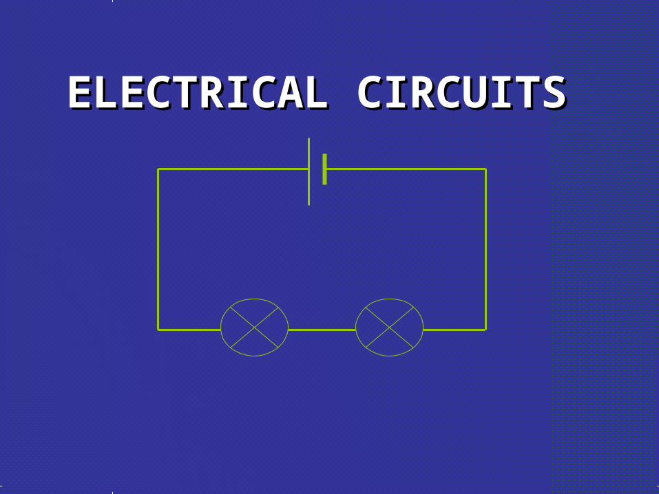
What is an electric current?
An electric current is a flow of microscopic
particles called electrons flowing through
wires and components.
+ -

simple circuitssimple circuits
Here is a simple electric circuit. It has a cell, a
lamp and a switch.
To make the circuit, these components are
connected together with metal connecting wires.
cell
lamp
switch
wires

simple circuitssimple circuitsWhen the switch is closed, the lamp lights up. This is because there is a continuous path of metal for the electric current to flow around.
If there were any breaks in the circuit, the current could not flow.

circuit diagramcircuit diagram
cell switch
lamp
wires
Scientists usually draw electric circuits using symbols;

circuit diagramscircuit diagramsIn circuit diagrams components are represented by the following symbols;
cell battery
switch
lamp
motorammeter
voltmeter
buzzer
resistor
variable resistor

types of circuittypes of circuit
There are two types of electrical circuits;
SERIES CIRCUITS PARALLEL CIRCUITS

The components are connected end-to-end, one after the other.
They make a simple loop for the current to flow round.
SERIES CIRCUITS
If one bulb ‘blows’ it breaks the whole circuit and all the bulbs go out.

Light Bulbs in SeriesLight Bulbs in Series
• Lights connected in a row, one after the other are IN SERIES
• REMOVE one bulb and the circuit is BROKEN• If Circuit is BROKEN, they all go out.

PARALLEL CIRCUITS
The current has a choice of routes.
The components are connected side by side.
If one bulb ‘blows’ there will still be a complete circuit to the other bulb so it stays alight.

measuring current
Electric current is measured in amps (A)
using an ammeter connected in series in
the circuit.
A

Light Bulbs in ParallelLight Bulbs in Parallel
• Lights connected on different wires that share the same current flow as the original wire provide multiple paths for electricity to flow.
• REMOVE one bulb and the circuit is STILL ACTIVE IN OTHER AREAS.
• Other remaining bulbs still have current and glow

measuring current
A A
This is how we draw an ammeter in a circuit.
SERIES CIRCUIT PARALLEL CIRCUIT

measuring currentSERIES CIRCUIT
PARALLEL CIRCUIT
• current is the same
at all points in the
circuit.
2A 2A
2A
• current is shared between the components
2A2A
1A
1A

copy the following circuits and fill in the missing ammeter readings.
?
?
4A
4A
4A
3A?
?
1A
?
3A
1A
1A

measuring voltage
The ‘electrical push’ which the cell gives to the
current is called the voltage. It is measured in
volts (V) on a voltmeter
V

Different cells produce different voltages. The
bigger the voltage supplied by the cell, the bigger
the current.
measuring voltage
Unlike an ammeter a voltmeter is connected
across the components
Scientist usually use the term Potential
Difference (pd) when they talk about voltage.

measuring voltage
V
This is how we draw a voltmeter in a circuit.
SERIES CIRCUIT PARALLEL CIRCUIT
V

series circuit
1.5V
• voltage is shared between the components
1.5V
3V

• voltage is the same in all parts of the circuit.
3V
parallel circuit
3V
3V

measuring current & voltage
copy the following circuits on the next two slides.
complete the missing current and voltage readings.
remember the rules for current and voltage in series and parallel circuits.

measuring current & voltage
V V
6V4A
A
A
a)a)

measuring current & voltage
V
V
6V4A A
A
A
b)b)

answers
3V 3V
6V
4A 4A6V
6V
6V4A 4A
2A
2A
4A
a)a) b)b)

Resistance means to “resist” or slow down the flow of current. RESISTORS are devices, like light bulbs, that make use of this slowing down of current.
SERIES CIRCUITS - RESISTANCE

Total Resistance in Series
•Resistance is measured with an Ohmmeter, named after the unit of
Resistance, the Ohm .
•In a series circuit, you ADD all the resistance in that wire section together. 3 3
3 + 3 = 6 total

PARALLEL CIRCUITS - RESISTANCE
Resistance along a parallel circuit is reduced because you give the current another way to go, multiple paths!!
BUT THINGS GET WEEEEEIRD when you add these up...

Total Resistance in Parallel
(1/R1 + 1/R2) = 1/Rtotal
In a parallel circuit, you ADD the INVERSE of all the resistance in that wire section together and then take the inverse of the answer…
You are making the pathway BIGGER for the current to flow through by putting resistors side by side – parallel.
3
3
1/3 + 1/3 = 2/3 now flip and divide
1/Rtotal = 2/3 (then press 1/x button) = 1.5

Results
When you added these two together inversely, the total resistance was LOWER than either of the resistors.
That is because you are providing more area for the charge to flow, so you are reducing resistance.
3
3
1.5 Total

WHICH IS BRIGHTER?WHICH IS BRIGHTER?So… you know that resistance is different in these circuits. Which type of circuit would allow current to flow faster, making the brightest bulbs?SERIES CIRCUITS PARALLEL
CIRCUITS
? ???

WHICH IS BRIGHTER?WHICH IS BRIGHTER?The bulbs in PARALLEL will be brighter because the circuit allows current to flow more easily
SERIES CIRCUITS PARALLEL CIRCUITS
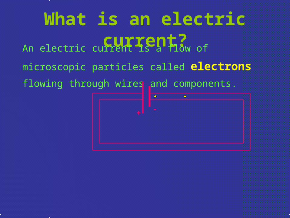
Combination Circuits
• Combo circuits contain both parallel and series portions in one single circuit.

Solving Combo Circuits – STEP 1
• Solve for the Current going through the total circuit.
• STEP 1 • Calculate total
resistance of Parallel path first.
• (1/3 + 1/9) = 1/0.44• = 2.25

Solving Combo Circuits – STEP 2
• Solve for the Current going through the total circuit.
• STEP 2 • Now it is as if the circuit
is just a bunch of resistors in series, EASY!
• Add the resistance together to get the total:
• 2.25 + 12 + 6 = 20.25
2.25

Solving Combo Circuits – STEP 3
• Solve for the Current going through the total circuit.
• STEP 3 • Total R = 20.25 • I = V / R = 120/20.25
• I = 6 A
2.25

Solving Combo Circuits CHALLENGE
• Solve for the Current going over the 3 resistor ONLY

Solving Combo Circuits – STEP 1
• Solve for the Current going over the 3 resistor
• STEP 1 • Remember that current
along a series circuit is always the same at all points.
• Current in a parallel circuit is shared according to I = V / R
6A
6A
6A
6A?
?

Solving Combo Circuits – STEP 2• Solve for the Current going over the 3 resistor
STEP 2• Must find the voltage going
across the parallel path!!!• Voltage at parallel branch
= the total I X total R of the branch
• Total I = 6 A• Total R = 2.25 • V = 13.5 V 6A
6A
6A
6A13.5 V
13.5 V
?
?

Solving Combo Circuits – STEP 3• Solve for the Current going over the 3 resistor
STEP 3• V = 13.5 V• Now just calculate current
at 3 resistor• I = V / R = 13.5 / 3 = 4.5 A• And at the 9 resistor• I = V / R = 13.5 / 9 = 1.5 A
6A
6A
6A
6A13.5 V
13.5 V
4.5 A
1.5 A

Power in Circuits
• Remember that power is just a measure of how fast you do work.
• In circuits Power is the same. Work is voltage and the rate is Current
• Unit of Power is a Watt
• P = VI

Calculate Current with Power
• A 40 Watt light bulb is connected to a standard 120 V outlet.
• What is the current being drawn through the bulb?
• P = VI… I = P / V = 40 / 120 = 0.33 A
• A brighter 100 W bulb?
• 0.83 A
• More current = More power usually


![ELECTRICAL SYSTEM El]: - kiruji.net Electrical System.pdf · ELECTRICAL SYSTEM SECTION El]:: When you read wiring diagrams: • Read GI section, "HOW TO READ WIRING DIAGRAMS". When](https://img.pdfslide.net/doc/110x75/5aa55f027f8b9ac8748d0c0e/electrical-system-el-electrical-systempdfelectrical-system-section-el-when.jpg)