Embed Size (px)
Citation preview
2D
WIRING DIAGRAMS
90-855347R1 JANUARY 1999 Page 2D-1
ELECTRICALSection 2D – Wiring Diagrams
Table of Contents
Power Trim Wiring Diagram 2D-2. . . . . . . . . . . . . . . . . . . Instrument Wiring Connections 2D-3. . . . . . . . . . . . . . . . . Commander 3000 Classic Panel Remote Control 2D-4. Commander 3000 Panel Remote Control 2D-5. . . . . . . . Instrument/Lanyard Stop Switch Wiring Diagram 2D-6. Oil Level Gauge Wiring Diagram 2D-7. . . . . . . . . . . . . . . Instrument/Lanyard Stop Switch Wiring Diagram(Dual Outboard) 2D-8. . . . . . . . . . . . . . . . . . . . . . . . . . . . . . QSI Gauge Wiring Diagrams 2D-10. . . . . . . . . . . . . . . . .
Tachometer Wiring Diagram 2D-10. . . . . . . . . . . . . . Water Temperature Gauge 2D-11. . . . . . . . . . . . . . . .
Oil Level Gauge Wiring 2D-12. . . . . . . . . . . . . . . . . . . Engine Synchronizer Wiring Diagram 2D-14. . . . . .
Maintenance 2D-15. . . . . . . . . . . . . . . . . . . . . . . . . . . . . . . Multi-Function Gauge 2D-16. . . . . . . . . . . . . . . . . . . . . . .
Dip Switch Setting/Testing 2D-16. . . . . . . . . . . . . . . . Outboard Multi-Function Gauge Setting 2D-17. . . . Warning System Signals 2D-18. . . . . . . . . . . . . . . . . Warning System Operation 2D-19. . . . . . . . . . . . . . .
Panel Mount Remote Control Wiring Installation 2D-221998 135/150 DFI Wiring Diagram 2D-23. . . . . . . . . . . . 1999 135/150 DFI Wiring Diagram 2D-24. . . . . . . . . . . .
WIRING DIAGRAMS
Page 2D-2 90-855347R1 JANUARY 1999
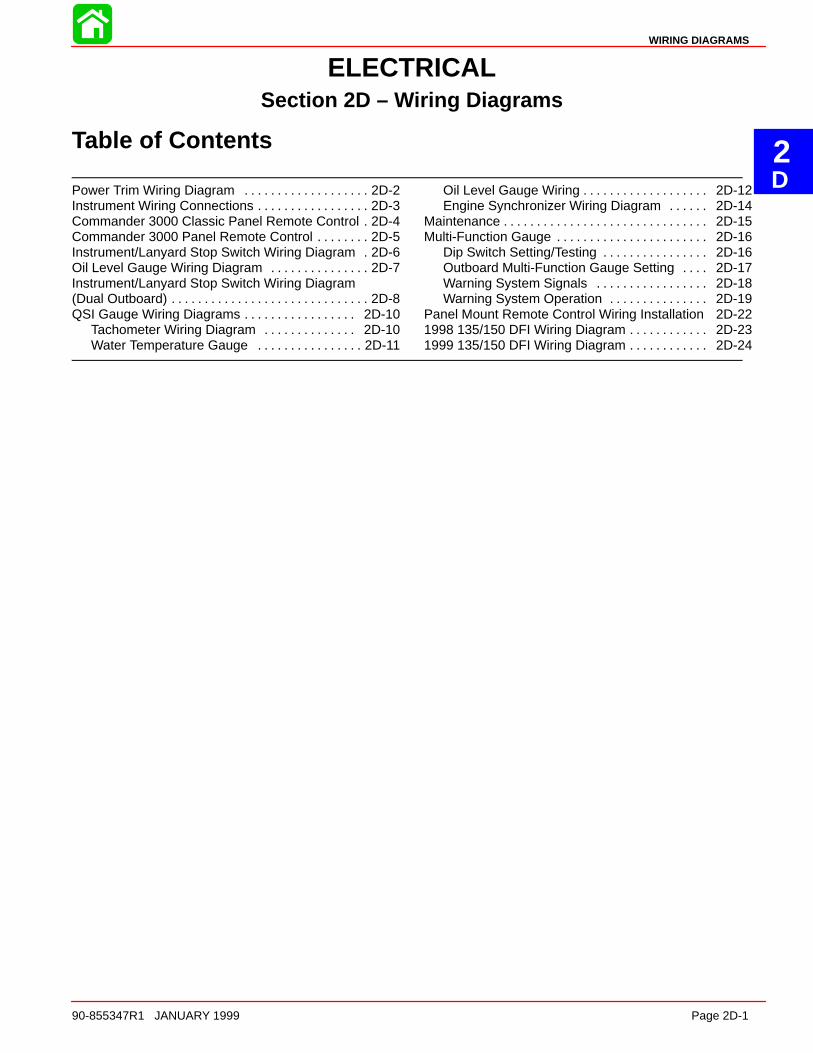
Power Trim Wiring Diagram
a bc
d
e
f
g
hij
k
l
m
n
a bc
d
e
f
g
hij
k
l
m
n
a - Tach. Connectorb - Key Switch Assemblyc - Trim Switchd - Trim Sendere - Start Solenoidf - To Batteryg - To Alternator
h - Trim Pump and Motori - DOWN Solenoidj - UP Solenoidk - Bottom Cowl Switchl - 20 Ampere Fuse
m - Engine Harnessn - Remote Control Harness
WIRING DIAGRAMS
90-855347R1 JANUARY 1999 Page 2D-3
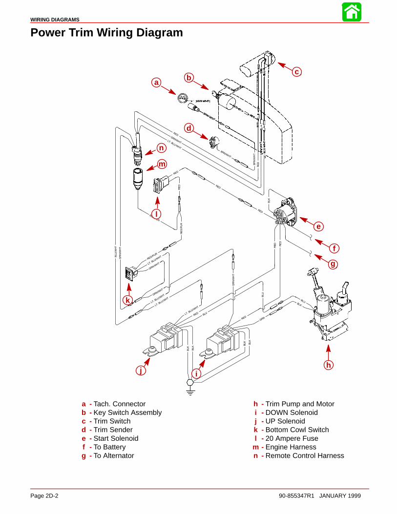
Instrument Wiring Connections
Speedometer Tachometer
Temperature/Oil Warning Panel Volt Meter
TAN/WHTTAN/BLK
51820
a b
d
c
BLK = BLACK GROUNDTAN/WHT = TAN/WHITE OIL LIGHTTAN/BLK = TAN/BLACK TEMPERATURE LIGHTTAN = TAN TEMPERATURE GAUGEPUR = PURPLE IGNITION 12 VOLTGRY = GRAY TACHOMETERBRN/WHT = BROWN/WHITE TRIM GAUGETAN/BLU = TAN/BLUE VISUAL WARNING KIT (OPT.)
Wire Color Where To
a bc
d
Figure 1 – Without Light Switch
NOTE: ANY INSTRUMENT WIRING HARNESS LEADS NOT USED MUST BE TAPEDBACK TO THE HARNESS.
TAN/WHTTAN/BLK
Speedometer Tachometer
Temperature/Oil Warning Panel Volt Meter
51819
To 12V
e
a b
d
ca b
c
d
e
Figure 2 – With Light Switcha - Tachometer Receptacle - From Control Box or Ignition/Choke Switchb - Tachometer Wiring Harnessc - Lead to Optional Visual Warning Kit (Taped Back to Harness)d - Cable Extension (For Two Function Warning Panel)e - Light Switch
WIRING DIAGRAMS
Page 2D-4 90-855347R1 JANUARY 1999
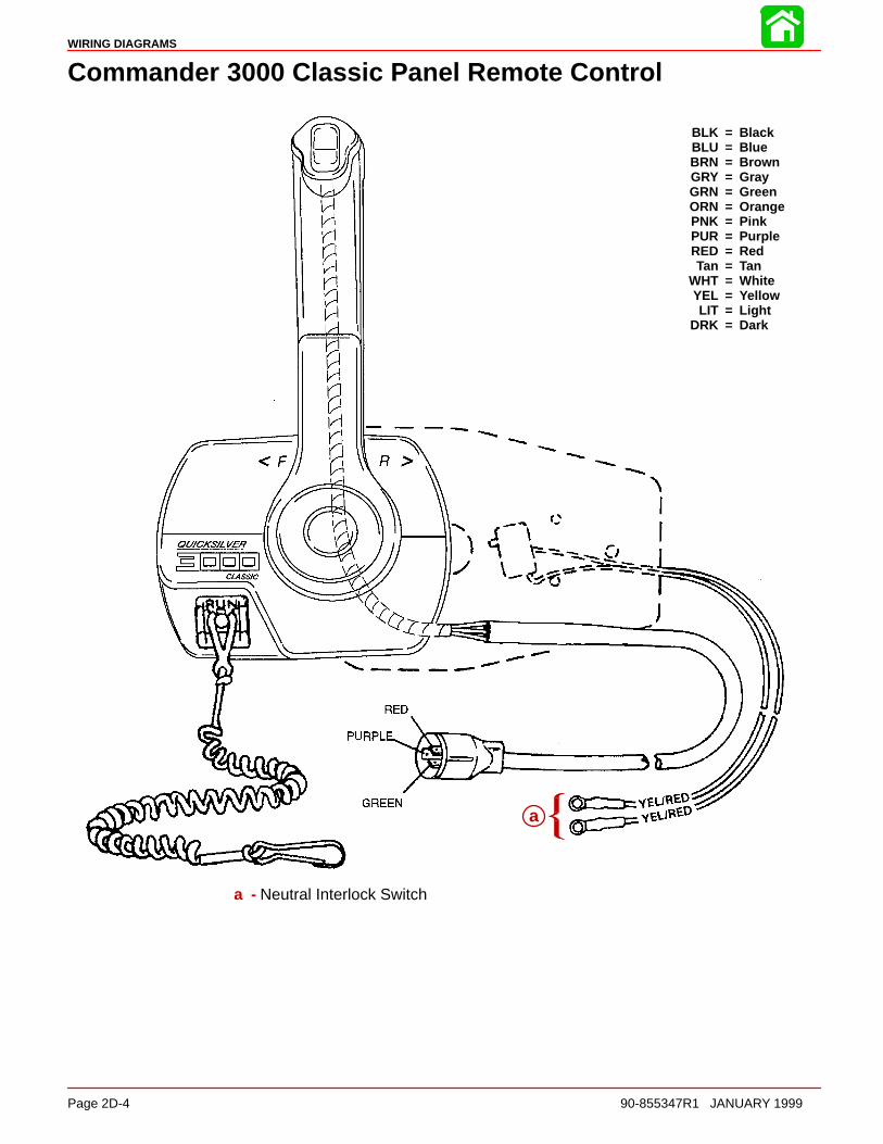
Commander 3000 Classic Panel Remote Control
BLK = BlackBLU = BlueBRN = BrownGRY = GrayGRN = GreenORN = OrangePNK = PinkPUR = PurpleRED = RedTan = Tan
WHT = WhiteYEL = YellowLIT = Light
DRK = Dark
a
a - Neutral Interlock Switch

WIRING DIAGRAMS
90-855347R1 JANUARY 1999 Page 2D-5
Commander 3000 Panel Remote Control
RED
PURPLE
GREEN
BLK = BlackBLU = BlueBRN = BrownGRY = GrayGRN = GreenORN = OrangePNK = PinkPUR = PurpleRED = RedTAN = Tan
WHT = WhiteYEL = YellowLIT = Light
DRK = Dark
aa
a - Neutral Interlock Switch
WIRING DIAGRAMS
Page 2D-6 90-855347R1 JANUARY 1999
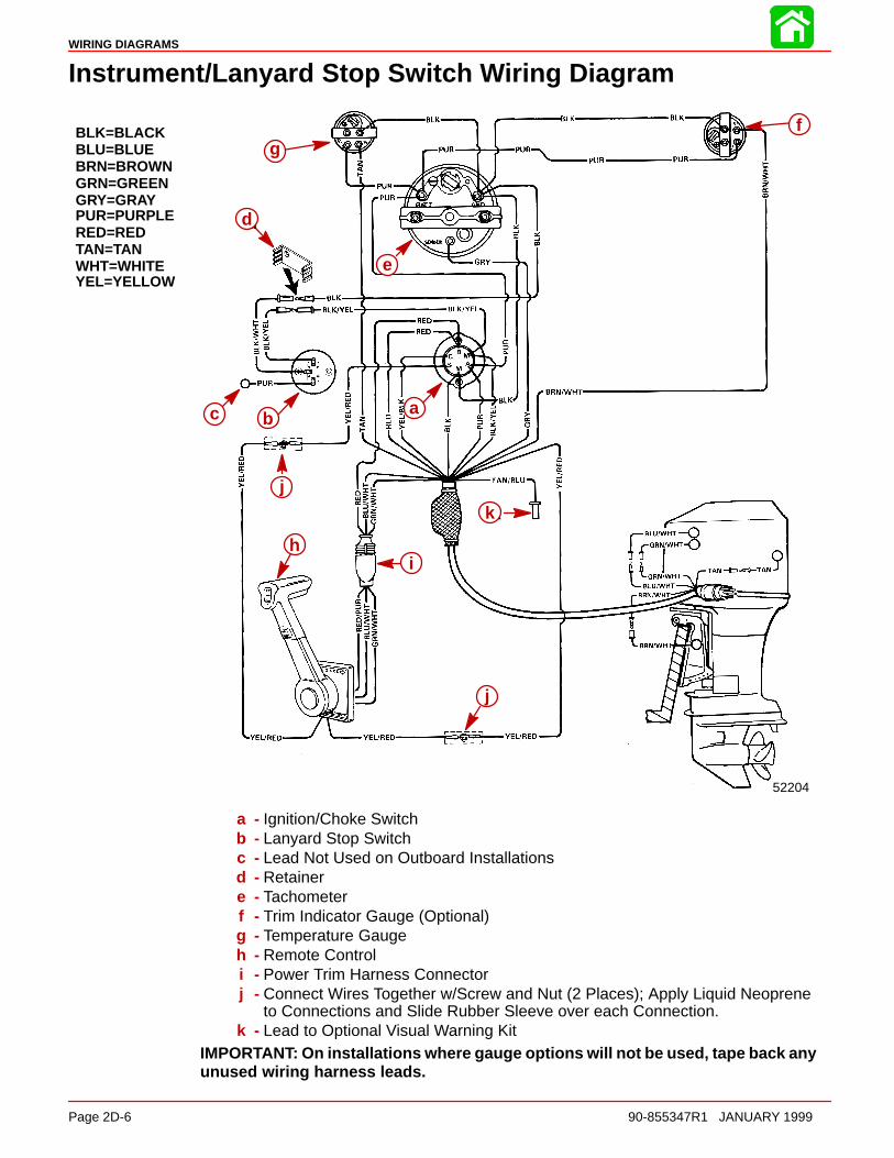
Instrument/Lanyard Stop Switch Wiring Diagram
BLK=BLACKBLU=BLUEBRN=BROWNGRN=GREENGRY=GRAYPUR=PURPLERED=REDTAN=TANWHT=WHITEYEL=YELLOW
52204
d
e
abc
j
i
k
j
h
fg
abc
d
e
hi
j
k
j
a - Ignition/Choke Switchb - Lanyard Stop Switchc - Lead Not Used on Outboard Installationsd - Retainere - Tachometerf - Trim Indicator Gauge (Optional)g - Temperature Gaugeh - Remote Controli - Power Trim Harness Connectorj - Connect Wires Together w/Screw and Nut (2 Places); Apply Liquid Neoprene
to Connections and Slide Rubber Sleeve over each Connection.k - Lead to Optional Visual Warning Kit
IMPORTANT: On installations where gauge options will not be used, tape back anyunused wiring harness leads.
WIRING DIAGRAMS
90-855347R1 JANUARY 1999 Page 2D-7
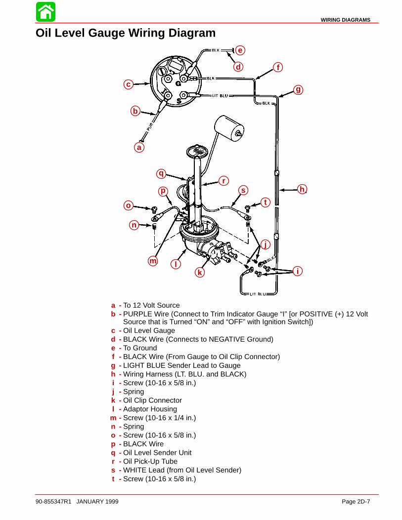
Oil Level Gauge Wiring Diagram
a
b
c
i
o
m
n
j
kl
h
g
f
p
qr
s
t
e
d
a
b
c
d
e
f
g
h
i
j
klm
n
o
p
qr
s
t
a - To 12 Volt Sourceb - PURPLE Wire (Connect to Trim Indicator Gauge “I” [or POSITIVE (+) 12 Volt
Source that is Turned “ON” and “OFF” with Ignition Switch])c - Oil Level Gauged - BLACK Wire (Connects to NEGATIVE Ground)e - To Groundf - BLACK Wire (From Gauge to Oil Clip Connector)g - LIGHT BLUE Sender Lead to Gaugeh - Wiring Harness (LT. BLU. and BLACK)i - Screw (10-16 x 5/8 in.)j - Springk - Oil Clip Connectorl - Adaptor Housing
m - Screw (10-16 x 1/4 in.)n - Springo - Screw (10-16 x 5/8 in.)p - BLACK Wireq - Oil Level Sender Unitr - Oil Pick-Up Tubes - WHITE Lead (from Oil Level Sender)t - Screw (10-16 x 5/8 in.)
WIRING DIAGRAMS
Page 2D-8 90-855347R1 JANUARY 1999
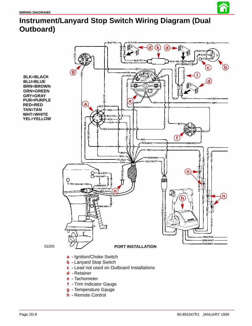
Instrument/Lanyard Stop Switch Wiring Diagram (DualOutboard)
BLK=BLACKBLU=BLUEBRN=BROWNGRN=GREENGRY=GRAYPUR=PURPLERED=REDTAN=TANWHT=WHITEYEL=YELLOW
52205
g
ae
d k d
bc
ld
f
n
nh
o
BATT GND
SENDER
PORT INSTALLATION
a
g
d k d
c b
ld
e
f
n
nh
o
a - Ignition/Choke Switchb - Lanyard Stop Switchc - Lead not used on Outboard Installationsd - Retainere - Tachometerf - Trim Indicator Gaugeg - Temperature Gaugeh - Remote Control
WIRING DIAGRAMS
90-855347R1 JANUARY 1999 Page 2D-9
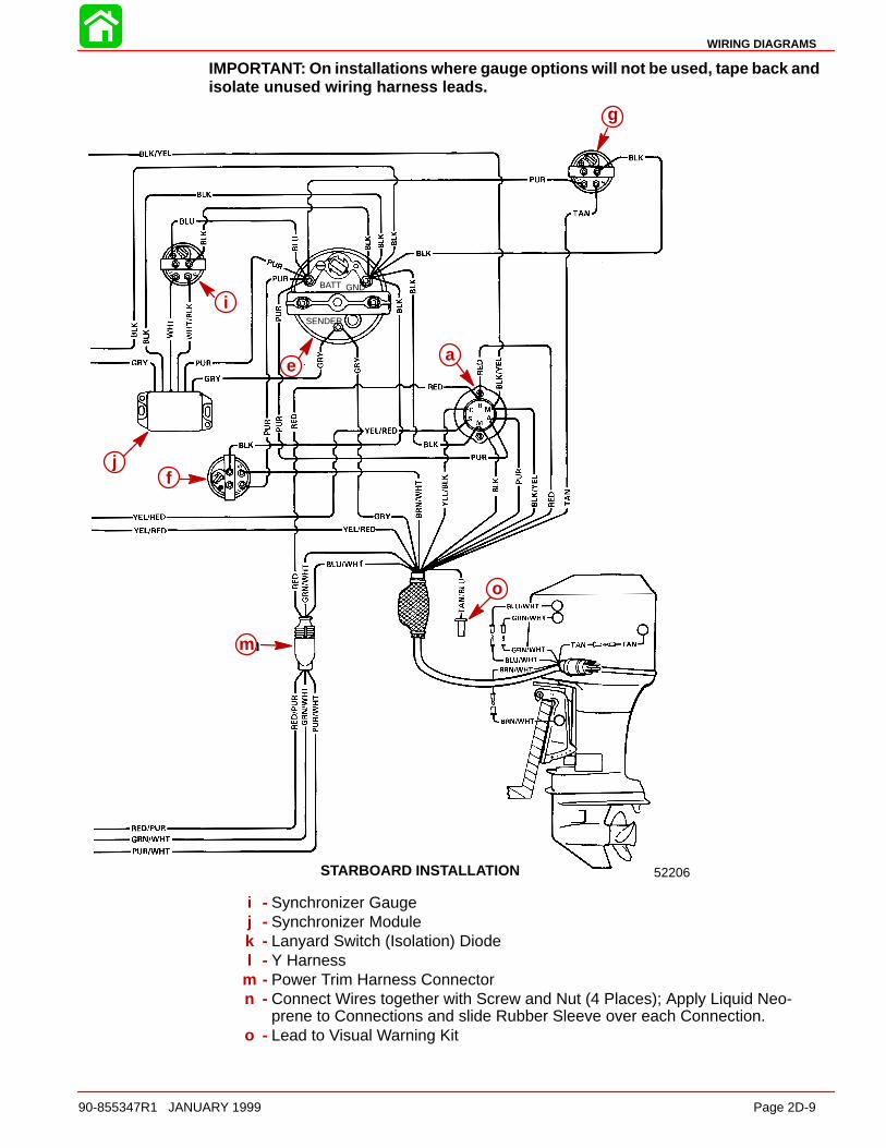
IMPORTANT: On installations where gauge options will not be used, tape back andisolate unused wiring harness leads.
52206
i
g
ae
jf
m
o
STARBOARD INSTALLATION
BATT GND
SENDER
g
i
jf
m
o
ae
i - Synchronizer Gaugej - Synchronizer Modulek - Lanyard Switch (Isolation) Diodel - Y Harness
m - Power Trim Harness Connectorn - Connect Wires together with Screw and Nut (4 Places); Apply Liquid Neo-
prene to Connections and slide Rubber Sleeve over each Connection.o - Lead to Visual Warning Kit
WIRING DIAGRAMS
Page 2D-10 90-855347R1 JANUARY 1999
QSI Gauge Wiring Diagrams
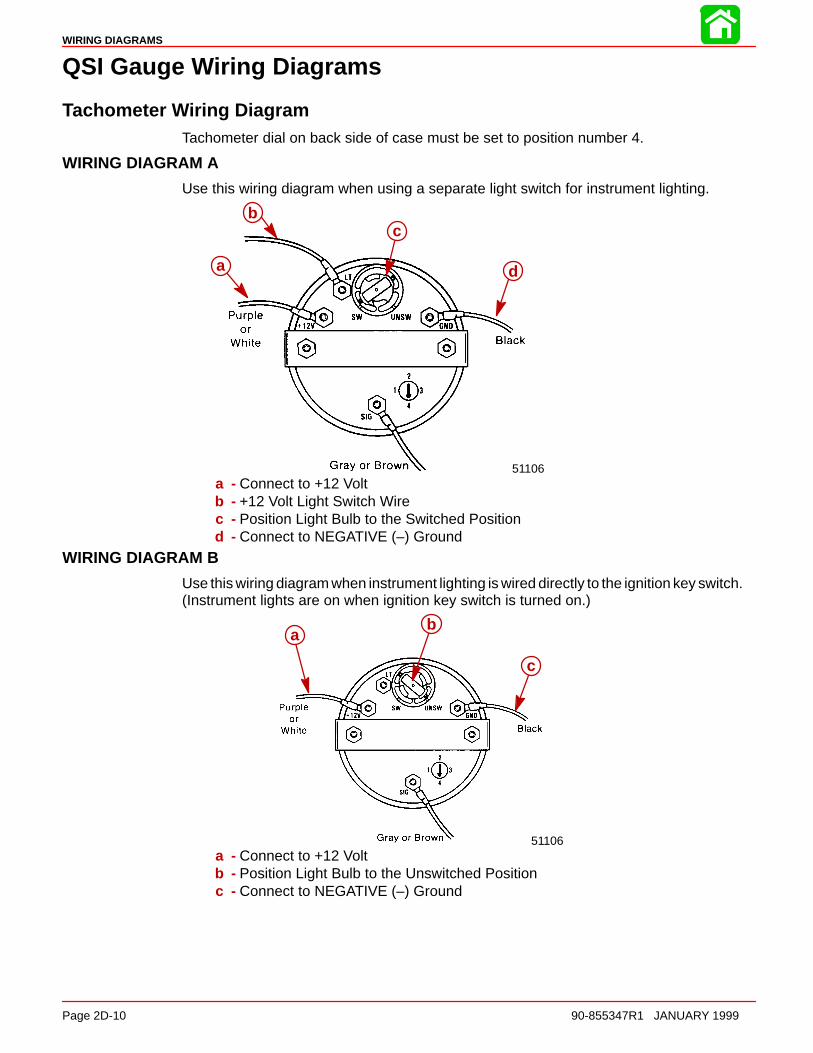
Tachometer Wiring DiagramTachometer dial on back side of case must be set to position number 4.
WIRING DIAGRAM A
Use this wiring diagram when using a separate light switch for instrument lighting.
51106
a
c
d
b
a - Connect to +12 Voltb - +12 Volt Light Switch Wirec - Position Light Bulb to the Switched Positiond - Connect to NEGATIVE (–) Ground
WIRING DIAGRAM B
Use this wiring diagram when instrument lighting is wired directly to the ignition key switch.(Instrument lights are on when ignition key switch is turned on.)
51106
ab
c
a - Connect to +12 Voltb - Position Light Bulb to the Unswitched Positionc - Connect to NEGATIVE (–) Ground
WIRING DIAGRAMS
90-855347R1 JANUARY 1999 Page 2D-11
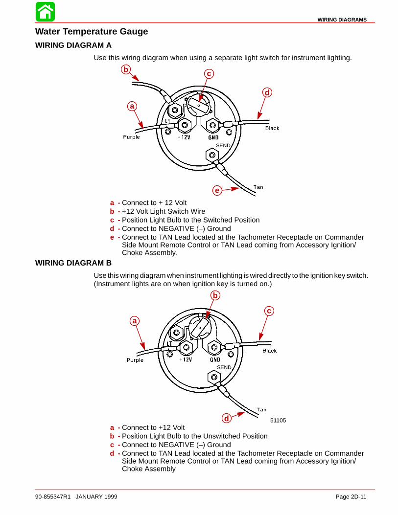
Water Temperature GaugeWIRING DIAGRAM A
Use this wiring diagram when using a separate light switch for instrument lighting.
SEND
a
b c
d
e
a - Connect to + 12 Voltb - +12 Volt Light Switch Wirec - Position Light Bulb to the Switched Positiond - Connect to NEGATIVE (–) Grounde - Connect to TAN Lead located at the Tachometer Receptacle on Commander
Side Mount Remote Control or TAN Lead coming from Accessory Ignition/Choke Assembly.
WIRING DIAGRAM B
Use this wiring diagram when instrument lighting is wired directly to the ignition key switch.(Instrument lights are on when ignition key is turned on.)
51105
SEND
a
b
c
da - Connect to +12 Voltb - Position Light Bulb to the Unswitched Positionc - Connect to NEGATIVE (–) Groundd - Connect to TAN Lead located at the Tachometer Receptacle on Commander
Side Mount Remote Control or TAN Lead coming from Accessory Ignition/Choke Assembly
WIRING DIAGRAMS
Page 2D-12 90-855347R1 JANUARY 1999
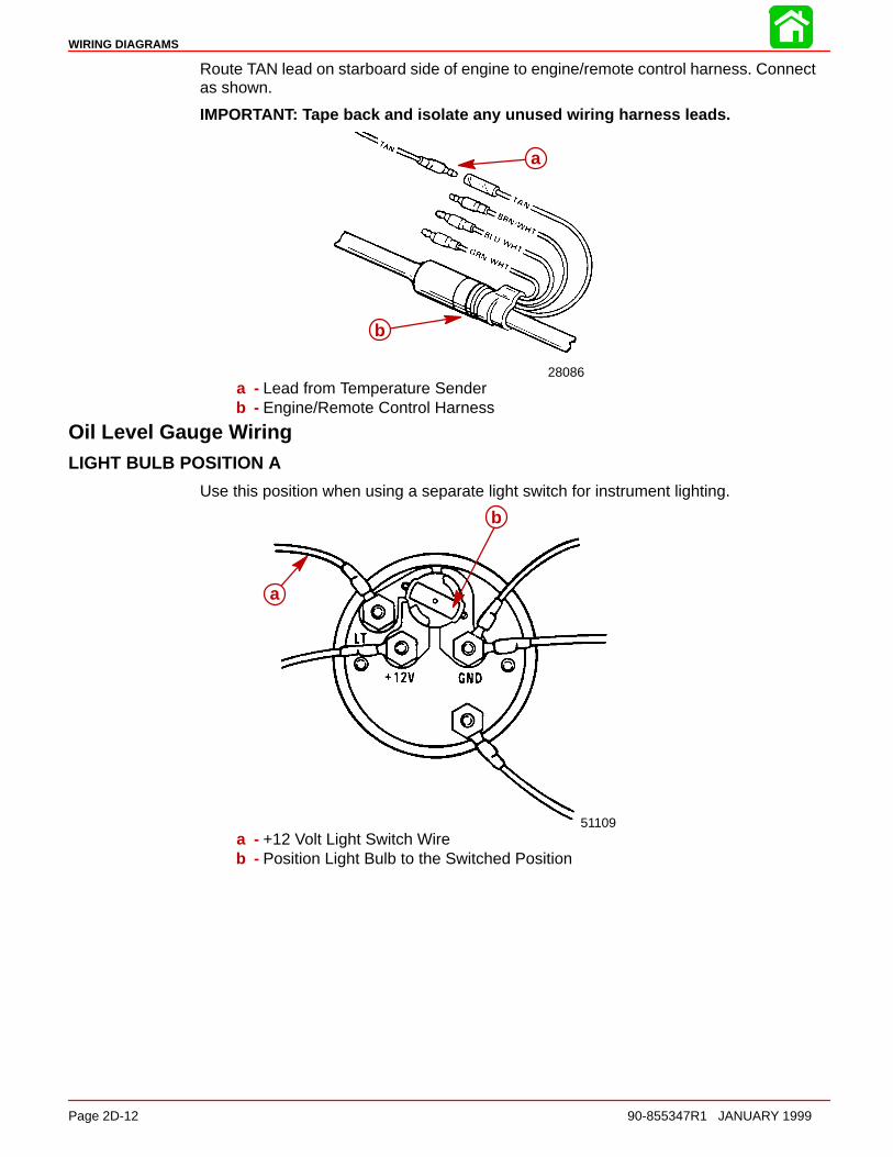
Route TAN lead on starboard side of engine to engine/remote control harness. Connectas shown.
IMPORTANT: Tape back and isolate any unused wiring harness leads.
28086
a
b
a - Lead from Temperature Senderb - Engine/Remote Control Harness
Oil Level Gauge WiringLIGHT BULB POSITION A
Use this position when using a separate light switch for instrument lighting.
51109
a
b
a - +12 Volt Light Switch Wireb - Position Light Bulb to the Switched Position
WIRING DIAGRAMS
90-855347R1 JANUARY 1999 Page 2D-13
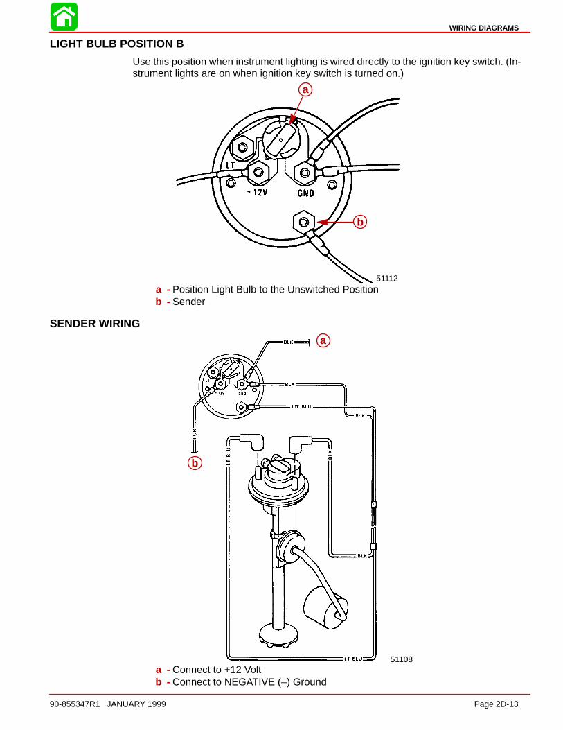
LIGHT BULB POSITION B
Use this position when instrument lighting is wired directly to the ignition key switch. (In-strument lights are on when ignition key switch is turned on.)
51112
a
b
a - Position Light Bulb to the Unswitched Positionb - Sender
SENDER WIRING
51108
a
b
a
b
a - Connect to +12 Voltb - Connect to NEGATIVE (–) Ground
WIRING DIAGRAMS
Page 2D-14 90-855347R1 JANUARY 1999
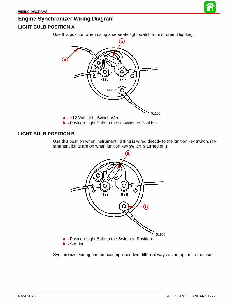
Engine Synchronizer Wiring DiagramLIGHT BULB POSITION A
Use this position when using a separate light switch for instrument lighting.
SEND
51105
a
b
a - +12 Volt Light Switch Wireb - Position Light Bulb to the Unswitched Position
LIGHT BULB POSITION B
Use this position when instrument lighting is wired directly to the ignition key switch. (In-strument lights are on when ignition key switch is turned on.)
51106
a
b
a - Position Light Bulb to the Switched Positionb - Sender
Synchronizer wiring can be accomplished two different ways as an option to the user.
WIRING DIAGRAMS
90-855347R1 JANUARY 1999 Page 2D-15
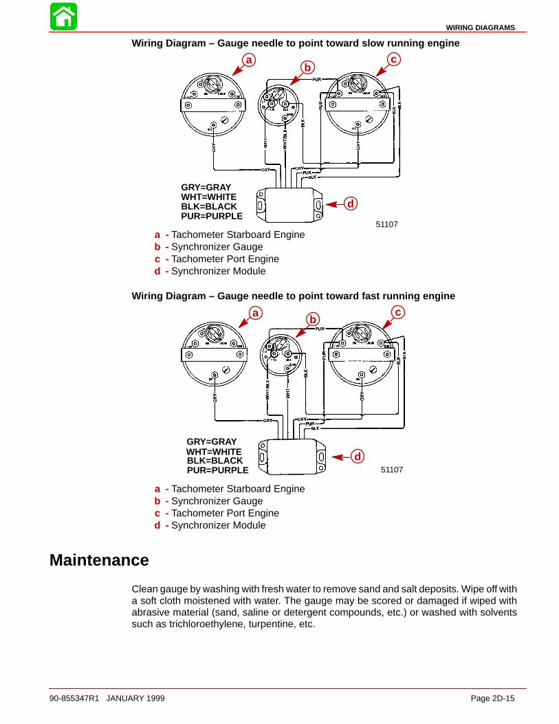
Wiring Diagram – Gauge needle to point toward slow running engine
GRY=GRAYWHT=WHITEBLK=BLACKPUR=PURPLE
51107
bc
d
ab
c
d
a - Tachometer Starboard Engineb - Synchronizer Gaugec - Tachometer Port Engined - Synchronizer Module
Wiring Diagram – Gauge needle to point toward fast running engine
GRY=GRAYWHT=WHITEBLK=BLACKPUR=PURPLE
bc
d51107
ab
c
d
a - Tachometer Starboard Engineb - Synchronizer Gaugec - Tachometer Port Engined - Synchronizer Module
Maintenance
Clean gauge by washing with fresh water to remove sand and salt deposits. Wipe off witha soft cloth moistened with water. The gauge may be scored or damaged if wiped withabrasive material (sand, saline or detergent compounds, etc.) or washed with solventssuch as trichloroethylene, turpentine, etc.
WIRING DIAGRAMS
Page 2D-16 90-855347R1 JANUARY 1999
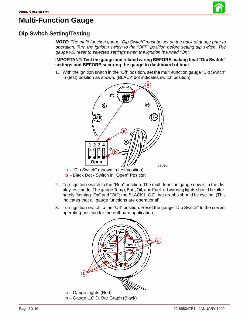
Multi-Function Gauge
Dip Switch Setting/TestingNOTE: The multi-function gauge “Dip Switch” must be set on the back of gauge prior tooperation. Turn the ignition switch to the “OFF” position before setting dip switch. Thegauge will reset to selected settings when the ignition is turned “On”.
IMPORTANT: Test the gauge and related wiring BEFORE making final “Dip Switch”settings and BEFORE securing the gauge to dashboard of boat.
1. With the ignition switch in the “Off” position, set the multi-function gauge “Dip Switch”in (test) position as shown. (BLACK dot indicates switch position).
a
b
52095Open
1 2 3 4
a
a
b
a - “Dip Switch” (shown in test position)b - Black Dot - Switch in “Open” Position
2. Turn ignition switch to the “Run” position. The multi-function gauge now is in the dis-play test mode. The gauge Temp, Batt, Oil, and Fuel red warning lights should be alter-nately flashing “On” and “Off”; the BLACK L.C.D. bar graphs should be cycling. (Thisindicates that all gauge functions are operational).
3. Turn ignition switch to the “Off” position. Reset the gauge “Dip Switch” to the correctoperating position for the outboard application.
b
aa
b
a - Gauge Lights (Red)b - Gauge L.C.D. Bar Graph (Black)
WIRING DIAGRAMS
90-855347R1 JANUARY 1999 Page 2D-17
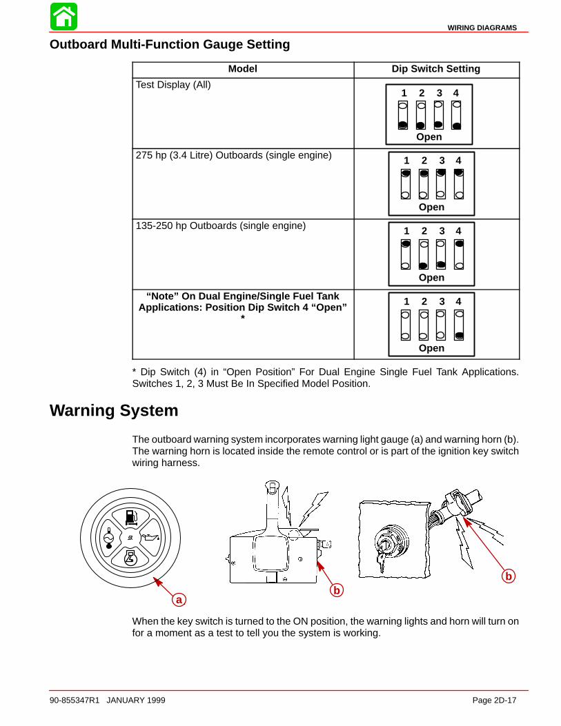
Outboard Multi-Function Gauge Setting
Model Dip Switch Setting
Test Display (All)
Open
1 2 3 4
275 hp (3.4 Litre) Outboards (single engine)
Open
1 2 3 4
135-250 hp Outboards (single engine)
Open
1 2 3 4
“Note” On Dual Engine/Single Fuel TankApplications: Position Dip Switch 4 “Open”
*
Open
1 2 3 4
* Dip Switch (4) in “Open Position” For Dual Engine Single Fuel Tank Applications.Switches 1, 2, 3 Must Be In Specified Model Position.
Warning System
The outboard warning system incorporates warning light gauge (a) and warning horn (b).The warning horn is located inside the remote control or is part of the ignition key switchwiring harness.
ab
b
ab
b
When the key switch is turned to the ON position, the warning lights and horn will turn onfor a moment as a test to tell you the system is working.
WIRING DIAGRAMS
Page 2D-18 90-855347R1 JANUARY 1999
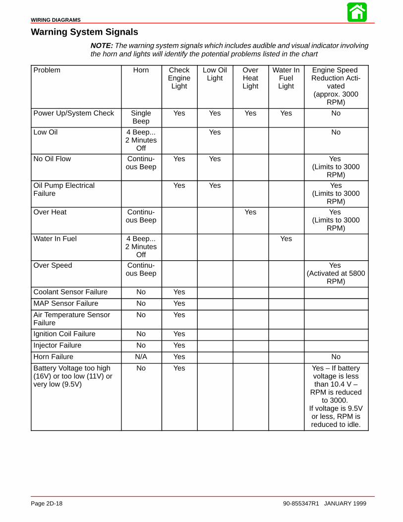
Warning System SignalsNOTE: The warning system signals which includes audible and visual indicator involvingthe horn and lights will identify the potential problems listed in the chart
Problem Horn CheckEngineLight
Low OilLight
OverHeatLight
Water InFuelLight
Engine Speed Reduction Acti-
vated(approx. 3000
RPM)
Power Up/System Check SingleBeep
Yes Yes Yes Yes No
Low Oil 4 Beep...2 Minutes
Off
Yes No
No Oil Flow Continu-ous Beep
Yes Yes Yes (Limits to 3000
RPM)
Oil Pump Electrical Failure
Yes Yes Yes(Limits to 3000
RPM)
Over Heat Continu-ous Beep
Yes Yes (Limits to 3000
RPM)
Water In Fuel 4 Beep...2 Minutes
Off
Yes
Over Speed Continu-ous Beep
Yes (Activated at 5800
RPM)
Coolant Sensor Failure No Yes
MAP Sensor Failure No Yes
Air Temperature SensorFailure
No Yes
Ignition Coil Failure No Yes
Injector Failure No Yes
Horn Failure N/A Yes No
Battery Voltage too high(16V) or too low (11V) orvery low (9.5V)
No Yes Yes – If batteryvoltage is lessthan 10.4 V –
RPM is reducedto 3000.
If voltage is 9.5Vor less, RPM isreduced to idle.
WIRING DIAGRAMS
90-855347R1 JANUARY 1999 Page 2D-19
Problem Horn CheckEngineLight
Low OilLight
OverHeatLight
Water InFuelLight
Engine Speed Reduction Acti-
vated(approx. 3000
RPM)
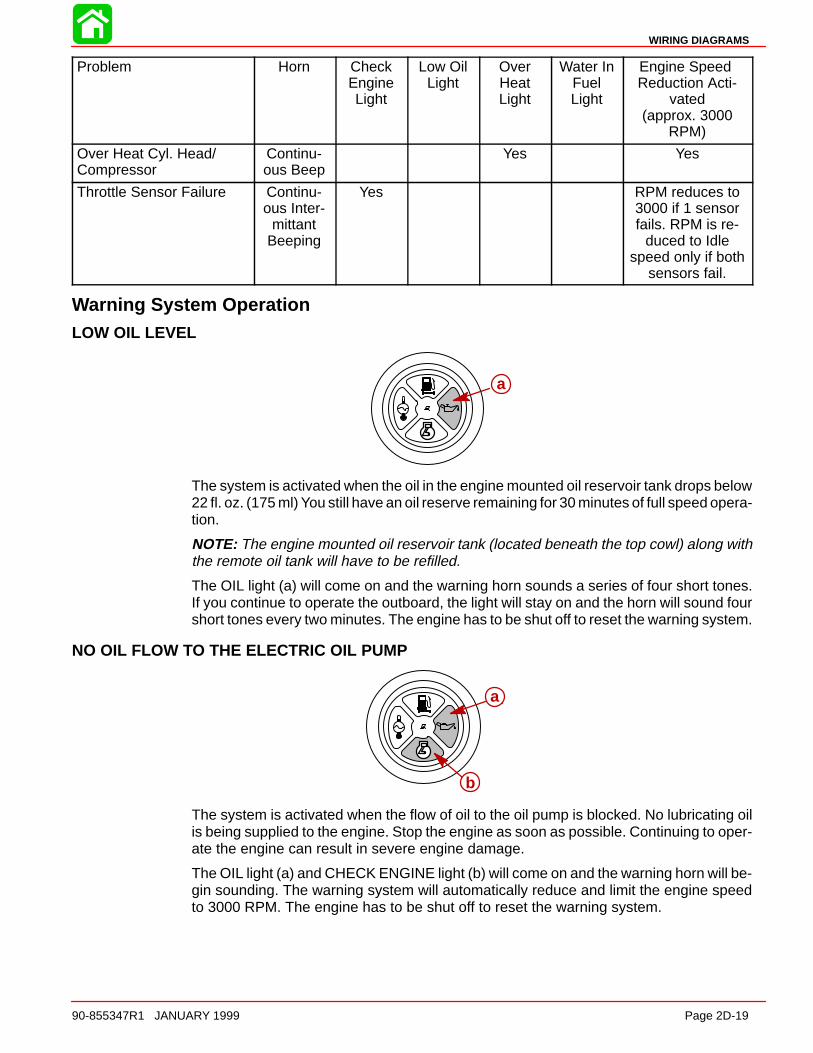
Over Heat Cyl. Head/Compressor
Continu-ous Beep
Yes Yes
Throttle Sensor Failure Continu-ous Inter-
mittantBeeping
Yes RPM reduces to3000 if 1 sensorfails. RPM is re-
duced to Idlespeed only if both
sensors fail.
Warning System OperationLOW OIL LEVEL
aa
The system is activated when the oil in the engine mounted oil reservoir tank drops below22 fl. oz. (175 ml) You still have an oil reserve remaining for 30 minutes of full speed opera-tion.
NOTE: The engine mounted oil reservoir tank (located beneath the top cowl) along withthe remote oil tank will have to be refilled.
The OIL light (a) will come on and the warning horn sounds a series of four short tones.If you continue to operate the outboard, the light will stay on and the horn will sound fourshort tones every two minutes. The engine has to be shut off to reset the warning system.
NO OIL FLOW TO THE ELECTRIC OIL PUMP
a
b
a
b
The system is activated when the flow of oil to the oil pump is blocked. No lubricating oilis being supplied to the engine. Stop the engine as soon as possible. Continuing to oper-ate the engine can result in severe engine damage.
The OIL light (a) and CHECK ENGINE light (b) will come on and the warning horn will be-gin sounding. The warning system will automatically reduce and limit the engine speedto 3000 RPM. The engine has to be shut off to reset the warning system.
WIRING DIAGRAMS
Page 2D-20 90-855347R1 JANUARY 1999
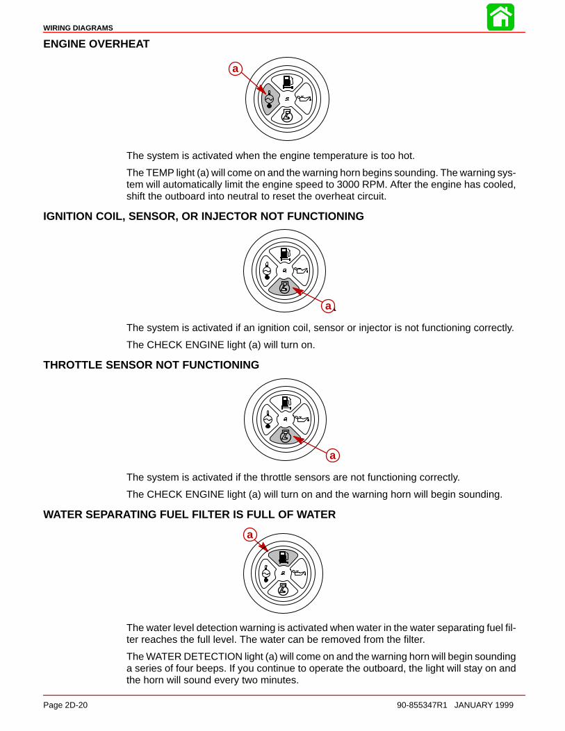
ENGINE OVERHEAT
aa
The system is activated when the engine temperature is too hot.
The TEMP light (a) will come on and the warning horn begins sounding. The warning sys-tem will automatically limit the engine speed to 3000 RPM. After the engine has cooled,shift the outboard into neutral to reset the overheat circuit.
IGNITION COIL, SENSOR, OR INJECTOR NOT FUNCTIONING
aa
The system is activated if an ignition coil, sensor or injector is not functioning correctly.
The CHECK ENGINE light (a) will turn on.
THROTTLE SENSOR NOT FUNCTIONING
aa
The system is activated if the throttle sensors are not functioning correctly.
The CHECK ENGINE light (a) will turn on and the warning horn will begin sounding.
WATER SEPARATING FUEL FILTER IS FULL OF WATER
a
The water level detection warning is activated when water in the water separating fuel fil-ter reaches the full level. The water can be removed from the filter.
The WATER DETECTION light (a) will come on and the warning horn will begin soundinga series of four beeps. If you continue to operate the outboard, the light will stay on andthe horn will sound every two minutes.
WIRING DIAGRAMS
90-855347R1 JANUARY 1999 Page 2D-21
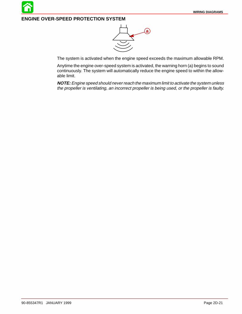
ENGINE OVER-SPEED PROTECTION SYSTEM
aa
The system is activated when the engine speed exceeds the maximum allowable RPM.
Anytime the engine over-speed system is activated, the warning horn (a) begins to soundcontinuously. The system will automatically reduce the engine speed to within the allow-able limit.
NOTE: Engine speed should never reach the maximum limit to activate the system unlessthe propeller is ventilating, an incorrect propeller is being used, or the propeller is faulty.
WIRING DIAGRAMS
Page 2D-22 90-855347R1 JANUARY 1999
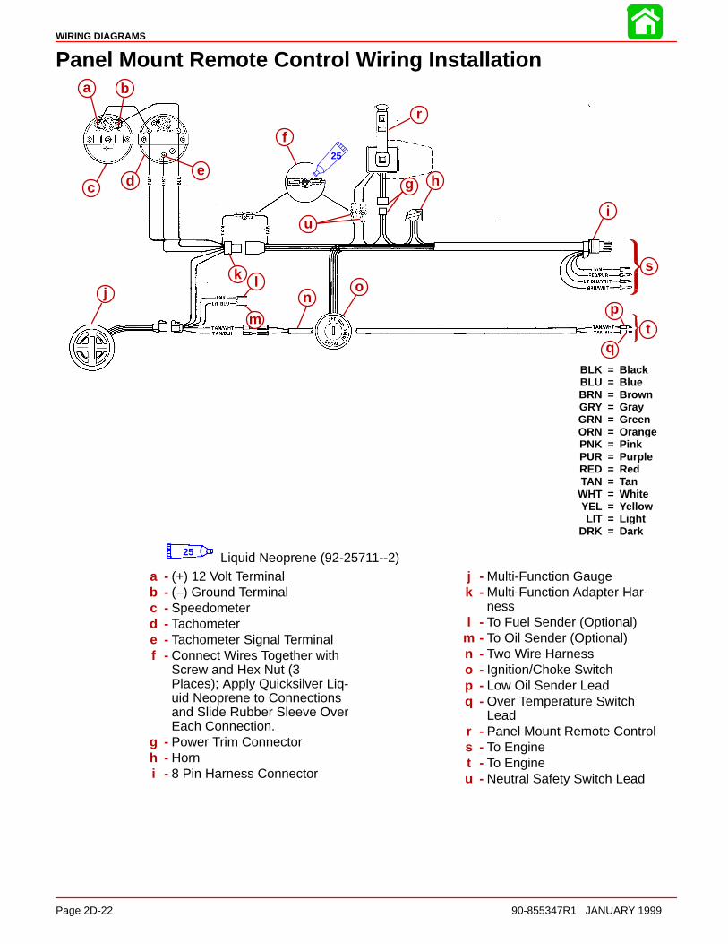
Panel Mount Remote Control Wiring Installation
BLK = BlackBLU = BlueBRN = BrownGRY = GrayGRN = GreenORN = OrangePNK = PinkPUR = PurpleRED = RedTAN = Tan
WHT = WhiteYEL = YellowLIT = Light
DRK = Dark
a b
c d
f
g h
r
ui
s
tp
q
on
m
lkj
e25
a b
c de
f
g h
i
jk l
m
no
p
q
r
s
t
u
25 Liquid Neoprene (92-25711--2)a - (+) 12 Volt Terminalb - (–) Ground Terminalc - Speedometerd - Tachometere - Tachometer Signal Terminalf - Connect Wires Together with
Screw and Hex Nut (3Places); Apply Quicksilver Liq-uid Neoprene to Connectionsand Slide Rubber Sleeve OverEach Connection.
g - Power Trim Connectorh - Horni - 8 Pin Harness Connector
j - Multi-Function Gaugek - Multi-Function Adapter Har-
nessl - To Fuel Sender (Optional)
m - To Oil Sender (Optional)n - Two Wire Harnesso - Ignition/Choke Switchp - Low Oil Sender Leadq - Over Temperature Switch
Leadr - Panel Mount Remote Controls - To Enginet - To Engineu - Neutral Safety Switch Lead
BLK = BlackBLU = BlueBRN = BrownGRY = GrayGRN = GreenORN = OrangePNK = PinkPUR = PurpleRED = RedTAN = Tan
WHT = WhiteYEL = Yellow
LT. = LightDK. = Dark
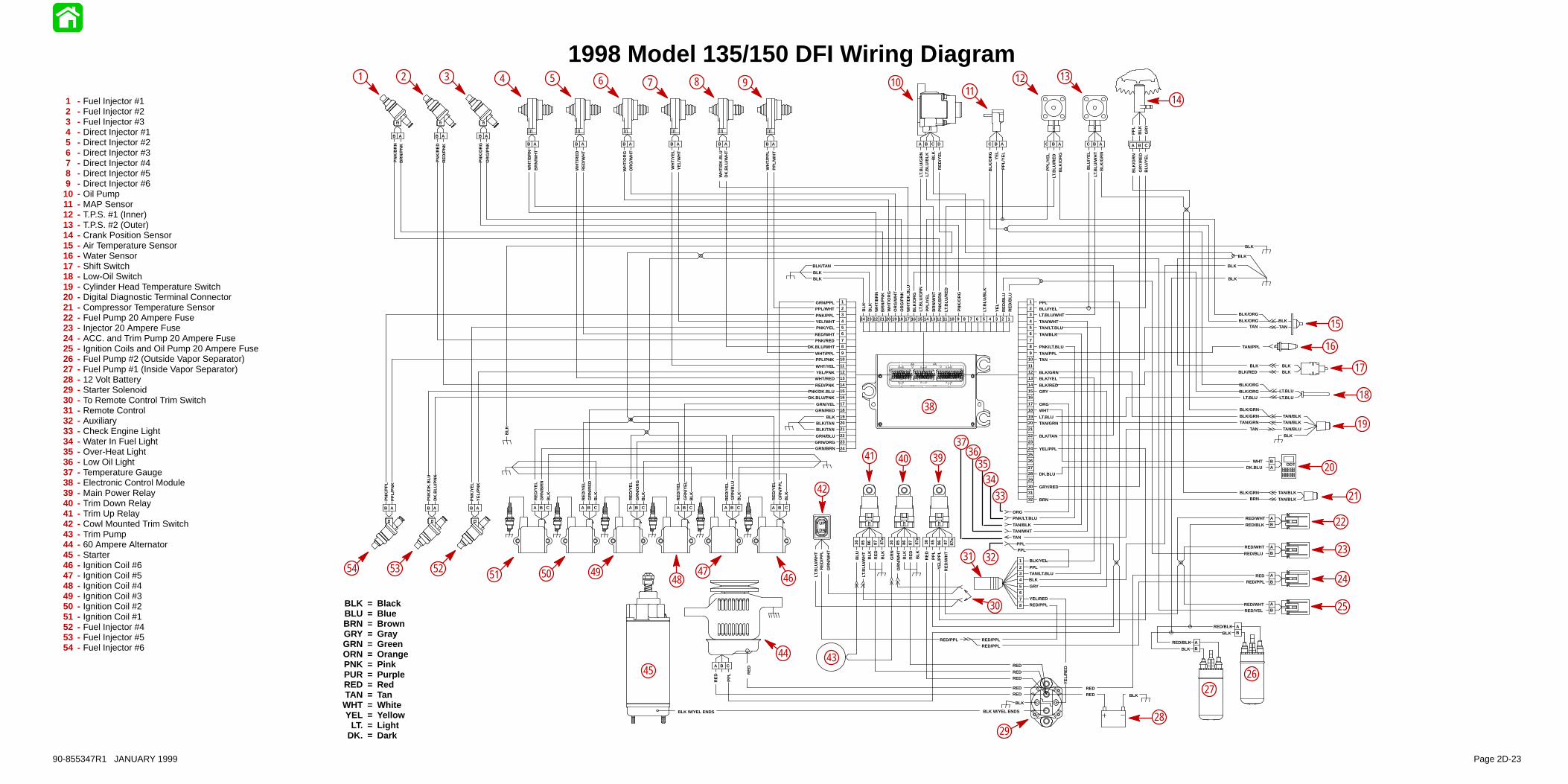
1998 Model 135/150 DFI Wiring Diagram
RE
D/B
LU
RE
D/B
LU
YE
L
LT.B
LU/B
LK
PN
K/O
RG
LT.B
LU/R
ED
PN
K/B
RN
BR
N/W
HT
BLK
/OR
GW
HT
/DK
.BLU
OR
G/P
NK
OR
G/W
HT
BR
N/P
NK
WH
T/B
RN
BLK
RE
D/Y
EL
PPLBLU/YEL
TAN/BLK
PNK/LT.BLU
TAN/PPLTAN
BLK/GRNBLK/YEL
WHT
LT.BLU
BLK/TAN
GRY/RED
GR
N/R
ED
RE
D/Y
EL
GR
N/O
RG
RE
D/Y
EL
GR
N/Y
EL
RE
D/Y
EL
GR
N/B
LU
RE
D/Y
EL
GR
N/P
PL
RE
D/Y
EL
GR
N/B
RN
WH
T/B
RN
BR
N/W
HT
WH
T/R
ED
RE
D/W
HT
WH
T/O
RG
OR
G/W
HT
WH
T/Y
EL
YE
L/W
HT
WH
T/D
K.B
LUD
K.B
LU/W
HT
WH
T/P
PL
PP
L/W
HT
GRN/PPLPPL/WHT
RED/WHTPNK/RED
DK.BLU/WHT
WHT/PPLPPL/PNK
WHT/YELYEL/PNK
WHT/RED
DK.BLU/PNK
GRN/YELGRN/RED
BLK
BLK/TAN
GRN/BLUGRN/ORG
PNK/PPLYEL/WHTPNK/YEL
RED/PNKPNK/DK.BLU
BLK/TAN
GRN/BRN
OR
G/P
NK
PN
K/O
RG
RE
D/P
NK
PN
K/R
ED
BR
N/P
NK
PN
K/B
RN
PP
L/Y
EL
LT.B
LU/G
RN
WH
T/O
RG
BLK
LT.B
LU/G
RN
LT.B
LU/B
LK BLK
RE
D/Y
EL
PP
L/Y
EL
LT.B
LU/R
ED
BLK
/OR
G
BLK
/GR
NLT
.BLU
/WH
T
BLU
/YE
L
PP
L/Y
EL
YE
LB
LK/O
RG
LT.BLU/WHT
TAN/WHTTAN/LT.BLU
BLK/REDGRY
TAN/GRN
YEL/PPL
DK.BLU
BLK
/GR
N
GR
Y/R
ED
BLU
/YE
L
ORG
TAN/PPL
TANBLK/ORG
PNK/LT.BLU
TAN/BLKTAN/WHT
ORG
TANBLK
TAN/BLKTAN/BLK
TAN/BLU
BLK
TAN
DN
UP
BLK
DDT
BRNBLK
BLK
BLK
BLK
BLK
BLK
PPLPPL
BLK/GRNTAN/GRN
TAN
BLK/GRN
LT.BLU
LT.BLUBLK/ORG
LT.BLU
1
23
456
78
910
111213
141516
1718
192021
2223
24
1
23
456
78
910
111213
141516
1718
192021
2223
242526
272829
3031
32
12345678109 11121314151618171920212223241 2345678 109 11121314151617181920222324252627282921303132
21 345678109 1112131415161817192021222324
123456789101112131415161718192021222324
BLK
DK
.BLU
/PN
K
PN
K/D
K.B
LU
YE
L/P
NK
PN
K/Y
EL
PP
L/P
NK
PN
K/P
PL
B A B A B A
B A B A B A
B A B A B A B A B A B A
A B CA B CA B CA B CA B CA B C
C DBA B AC B AC B AC A B C
BLK
PP
L
GR
Y
BLK/ORG
BLK/ORG
BLKBLK
BLKBLK/RED
TAN/BLK
TAN/BLK
BLK/GRNBRN
1
234
56
78
BLK/YEL
PPLTAN/LT.BLUBLK
GRY
YEL/REDRED/PPL
DK.BLUWHT
AB
86 878530 87a
GR
N/W
HT
GR
N
RE
DB
LK BLK
86 878530 87a
PP
L
RE
D
RE
D/W
HT
YE
L/P
PL
RED
RED/WHT
RED/WHT
RED/BLK
RED/BLU
RED/WHTRED/YEL
RED/PPL
BA
BA
B
A
BA
86 878530 87a
LT.B
LU/W
HT
BLU
RE
DB
LK
BLK
RED
A B C
RE
D
PP
L
REDRED
BLK
YE
L/R
ED
RED
RED
RED
BARED/BLK
BLK
BLK W/YEL ENDSBLK W/YEL ENDS
RED
RED/PPLRED/PPL
RED/PPL
RE
D/P
PL
LT.B
LU/W
HT
GR
N/W
HT
BLK
BLK
BLK
BLK
BLK
BLK/TAN
BLK
RE
D
BARED/BLK
BLK
1 - Fuel Injector #12 - Fuel Injector #23 - Fuel Injector #34 - Direct Injector #15 - Direct Injector #26 - Direct Injector #37 - Direct Injector #48 - Direct Injector #59 - Direct Injector #610 - Oil Pump11 - MAP Sensor12 - T.P.S. #1 (Inner)13 - T.P.S. #2 (Outer)14 - Crank Position Sensor15 - Air Temperature Sensor16 - Water Sensor17 - Shift Switch18 - Low-Oil Switch19 - Cylinder Head Temperature Switch20 - Digital Diagnostic Terminal Connector21 - Compressor Temperature Sensor22 - Fuel Pump 20 Ampere Fuse23 - Injector 20 Ampere Fuse24 - ACC. and Trim Pump 20 Ampere Fuse25 - Ignition Coils and Oil Pump 20 Ampere Fuse26 - Fuel Pump #2 (Outside Vapor Separator)27 - Fuel Pump #1 (Inside Vapor Separator)28 - 12 Volt Battery29 - Starter Solenoid30 - To Remote Control Trim Switch31 - Remote Control32 - Auxiliary33 - Check Engine Light34 - Water In Fuel Light35 - Over-Heat Light36 - Low Oil Light37 - Temperature Gauge38 - Electronic Control Module39 - Main Power Relay40 - Trim Down Relay41 - Trim Up Relay42 - Cowl Mounted Trim Switch43 - Trim Pump44 - 60 Ampere Alternator45 - Starter46 - Ignition Coil #647 - Ignition Coil #548 - Ignition Coil #449 - Ignition Coil #350 - Ignition Coil #251 - Ignition Coil #152 - Fuel Injector #453 - Fuel Injector #554 - Fuel Injector #6
6 7 8 9 1011
12 13
14
15
16
17
18
19
20
21
22
23
24
25
2627
2829
30
31 32
3435
3637
38
394041
42
4344
45
4647
4849
33
1 2 3 4 5
5051525354
90-855347R1 JANUARY 1999 Page 2D-23
BLK = BlackBLU = BlueBRN = BrownGRY = GrayGRN = GreenORN = OrangePNK = PinkPUR = PurpleRED = RedTAN = Tan
WHT = WhiteYEL = Yellow
LT. = LightDK. = Dark
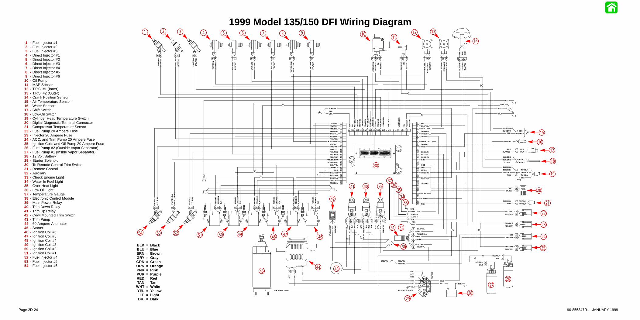
1999 Model 135/150 DFI Wiring Diagram
RE
D/B
LU
RE
D/B
LU
YE
L
LT.B
LU/B
LK
PN
K/O
RG
LT.B
LU/R
ED
PN
K/B
RN
BR
N/W
HT
BLK
/OR
GW
HT
/DK
.BLU
OR
G/P
NK
OR
G/W
HT
BR
N/P
NK
WH
T/B
RN
BLK
RE
D/Y
EL
PPLBLU/YEL
TAN/BLK
PNK/LT.BLU
TAN/PPLTAN
BLK/GRNBLK/YEL
WHT
LT.BLU
BLK/TAN
GRY/RED
GR
N/R
ED
RE
D/Y
EL
GR
N/O
RG
RE
D/Y
EL
GR
N/Y
EL
RE
D/Y
EL
GR
N/B
LU
RE
D/Y
EL
GR
N/P
PL
RE
D/Y
EL
GR
N/B
RN
WH
T/B
RN
BR
N/W
HT
WH
T/R
ED
RE
D/W
HT
WH
T/O
RG
OR
G/W
HT
WH
T/Y
EL
YE
L/W
HT
WH
T/D
K.B
LUD
K.B
LU/W
HT
WH
T/P
PL
PP
L/W
HT
GRN/PPLPPL/WHT
RED/WHTPNK/RED
DK.BLU/WHT
WHT/PPLPPL/PNK
WHT/YELYEL/PNK
WHT/RED
DK.BLU/PNK
GRN/YELGRN/RED
BLK
BLK/TAN
GRN/BLUGRN/ORG
PNK/PPLYEL/WHTPNK/YEL
RED/PNKPNK/DK.BLU
BLK/TAN
GRN/BRN
OR
G/P
NK
PN
K/O
RG
RE
D/P
NK
PN
K/R
ED
BR
N/P
NK
PN
K/B
RN
PP
L/Y
EL
LT.B
LU/G
RN
WH
T/O
RG
BLK
LT.B
LU/G
RN
LT.B
LU/B
LK BLK
PP
L/Y
EL
LT.B
LU/R
ED
BLK
/OR
G
BLK
/GR
NLT
.BLU
/WH
T
BLU
/YE
L
PP
L/Y
EL
YE
LB
LK/O
RG
LT.BLU/WHT
TAN/WHTTAN/LT.BLU
BLK/REDGRY
TAN/GRN
YEL/PPL
DK.BLU
BLK
/GR
N
GR
Y/R
ED
BLU
/YE
L
ORG
TAN/PPL
TANBLK/ORG
PNK/LT.BLU
TAN/BLKTAN/WHT
ORG
TANBLK
TAN/BLKTAN/BLK
TAN/BLU
BLK
TAN
DN
UP
BLK
DDT
BRNBLK
BLK
BLK
BLK
BLK
BLK
PPLPPL
BLK/GRNTAN/GRN
TAN
BLK/GRN
LT.BLU
LT.BLUBLK/ORG
LT.BLU
1
23
456
78
910
111213
141516
1718
192021
2223
24
1
23
456
78
910
111213
141516
1718
192021
2223
242526
272829
3031
32
12345678109 11121314151618171920212223241 2345678 109 11121314151617181920222324252627282921303132
21 345678109 1112131415161817192021222324
123456789101112131415161718192021222324
BLK
DK
.BLU
/PN
K
PN
K/D
K.B
LU
YE
L/P
NK
PN
K/Y
EL
PP
L/P
NK
PN
K/P
PL
B A B A B A
B A B A B A
B A B A B A B A B A B A
A B CA B CA B CA B CA B CA B C
C DBA B AC B AC B AC A B C
BLK
PP
L
GR
Y
BLK/ORG
BLK/ORG
BLKBLK
BLKBLK/RED
TAN/BLK
TAN/BLK
BLK/GRNBRN
1
234
56
78
BLK/YEL
PPLTAN/LT.BLUBLK
GRY
YEL/REDRED/PPL
DK.BLUWHT
AB
86 878530 87a
GR
N/W
HT
GR
N
RE
DB
LK BLK
86 878530 87a
PP
L
RE
D
RE
D/W
HT
YE
L/P
PL
RED
RED/WHT
RED/WHT
RED/BLK
RED/BLU
RED/WHTRED/YEL
RED/PPL
BA
BA
B
A
BA
86 878530 87a
LT.B
LU/W
HT
BLU
RE
DB
LK
BLK
RED
A B C
RE
D
PP
L
REDRED
BLK
YE
L/R
ED
RED
RED
RED
BARED/BLK
BLK
BLK W/YEL ENDSBLK W/YEL ENDS
RED
RED/PPLRED/PPL
RED/PPL
RE
D/P
PL
LT.B
LU/W
HT
GR
N/W
HT
BLK
BLK
BLK
BLK
BLK
BLK/TAN
BLK
RE
D
BARED/BLK
BLK
RE
D/B
LU
1 2 3 4 5 6 7 8 9 1011
12 13
14
15
16
17
18
19
20
21
22
23
24
25
2627
2829
30
31 32
3334
3536
37
38
394041
42
434445
464748495051525354
1 - Fuel Injector #12 - Fuel Injector #23 - Fuel Injector #34 - Direct Injector #15 - Direct Injector #26 - Direct Injector #37 - Direct Injector #48 - Direct Injector #59 - Direct Injector #610 - Oil Pump11 - MAP Sensor12 - T.P.S. #1 (Inner)13 - T.P.S. #2 (Outer)14 - Crank Position Sensor15 - Air Temperature Sensor16 - Water Sensor17 - Shift Switch18 - Low-Oil Switch19 - Cylinder Head Temperature Switch20 - Digital Diagnostic Terminal Connector21 - Compressor Temperature Sensor22 - Fuel Pump 20 Ampere Fuse23 - Injector 20 Ampere Fuse24 - ACC. and Trim Pump 20 Ampere Fuse25 - Ignition Coils and Oil Pump 20 Ampere Fuse26 - Fuel Pump #2 (Outside Vapor Separator)27 - Fuel Pump #1 (Inside Vapor Separator)28 - 12 Volt Battery29 - Starter Solenoid30 - To Remote Control Trim Switch31 - Remote Control32 - Auxiliary33 - Check Engine Light34 - Water In Fuel Light35 - Over-Heat Light36 - Low Oil Light37 - Temperature Gauge38 - Electronic Control Module39 - Main Power Relay40 - Trim Down Relay41 - Trim Up Relay42 - Cowl Mounted Trim Switch43 - Trim Pump44 - 60 Ampere Alternator45 - Starter46 - Ignition Coil #647 - Ignition Coil #548 - Ignition Coil #449 - Ignition Coil #350 - Ignition Coil #251 - Ignition Coil #152 - Fuel Injector #453 - Fuel Injector #554 - Fuel Injector #6
Page 2D-24 90-855347R1 JANUARY 1999