Embed Size (px)
Citation preview
NASA Technical Memorandum 88824
Electrical Power System Design for the U.S. Space Station
Donald L. Nored and Daniel T. Bernatowicz Lewis Research Center Cleveland, Ohio
4 NBS A-T PI-888 24) €LECT E IC AL E C W 1: B SYSTEI L E S X G N FOR T B E CS SPACE S T A l I C L ( N A S A ) 19 p
i Nd7-15267 I
CSCL 22b Uricia s
G3/20 40235
Prepared for the 2 1 st Intersociety Energy Conversion Engineering Conference (IECEC) cosponsored by the ACS, SAE, ANS, ASME, IEEE, AIM, and AIChE San Diego, California, August 25-29, 1986
https://ntrs.nasa.gov/search.jsp?R=19870005834 2018-07-13T08:32:18+00:00Z
ELECTRICAL POWER SYSTEM DESIGN FOR THE U.S. SPACE STATION
Donald L. Nored and Daniel T. Bernatowicz Nat iona l Aeronautics and Space Admin is t ra t ion
Lewis Research Center Cleveland, Ohio 44135
SUMMARY
The mult ipurpose, manned, permanent Space S t a t i o n w i l l be our next s tep toward u t i l i z a t i o n o f space. A m u l t i k i l o w a t t e l e c t r i c a l power system w i l l be c r i t i c a l t o i t s success. The power systems f o r t he Space S t a t i o n manned core and p la t fo rms t h a t have been se lected i n d e f i n i t i o n s tud ies a re descr ibed i n t h i s paper. The se lected system f o r the p la t fo rms uses s i l i c o n arrays and NI-H2 b a t t e r i e s . The power system f o r t he manned core i s a hyb r id employing ar rays and b a t t e r i e s i d e n t i c a l t o those on the p l a t f o r m a long w i t h s o l a r dynamic modules us ing e i t h e r Brayton o r organic Rankine engines. system requirements, candidate technologies, and con f igu ra t i ons t h a t were con- s idered, and t h e bas is f o r se lec t ion , a re discussed.
The power
BACKGROUND
The Space S t a t i o n Phase B Program was i n i t i a t e d i n 1984. Since then, NASA and i t s con t rac to rs have been involved i n the d e f i n i t i o n and p r e l i m i n a r y design o f t he Space S t a t i o n i n order t o e s t a b l i s h w i t h conf idence t h e cost , schedule, and performance be fore proceeding t o hardware development. The Space S t a t i o n Program invo lves t h e Space S ta t i on i t s e l f , which i s t he manned core, a p o l a r o r b i t i n g unmanned p la t fo rm, and a c o - o r b i t i n g unmanned p la t fo rm. Lewis has t h e r e s p o n s i b i l i t y f o r t he e l e c t r i c a l power system (EPS), and, a long w i t h i t s two cont rac tors - Racketdyne and TRW, conducted extens ive techn ica l and c o s t t r a d e s tud ies t o a r r i v e a t an EPS des ign d e f i n i t i o n f o r t h e s t a t i o n manned core and p la t fo rms. This paper addresses the r e s u l t i n g base l ine EPS design, as o f t he t ime o f w r i t i n g . a c t i v i t y w i l l , o f course, p rov ide updates t o t h i s design.
Cont inu ing trade s tud ies and the p re l im ina ry design
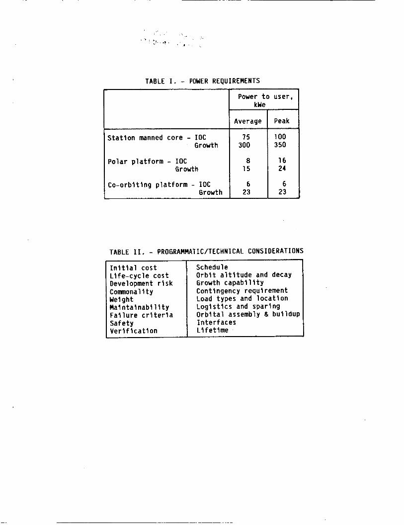
F igure 1 shows t h e s t a t i o n manned core concept. The EPS phys i ca l s i z e makes i t a p r i n c i p a l f ea tu re o f t h e s t a t i o n manned core geometry and a s i g - n i f i c a n t f a c t o r i n mass, s t a b i l i t y and c o n t r o l , and cos t . The la rge , m u l t i - purpose, evo lu t ionary na ture o f t he Space S t a t i o n program imposes requirements on the EPS t h a t a r e unique among space power systems. I t must be u s e r f r i e n d l y and adaptable t o a changing and evolv ing se t o f requirements. Thus, i t must be more l i k e a t e r r e s t r i a l u t i l i t y power system r a t h e r than the t y p i c a l f i x e d - purpose, dedicated, spacecraf t power system. The general power requirements f o r t h e EPS a re shown i n t a b l e I . (Note: Power l e v e l s on t h i s tab le , and throughout t h i s paper, a re g iven i n kWe t o t h e user, a f t e r d i s t r i b u t i o n losses .)
To meet these requirements, a va r ie t y o f opt ions f o r t h e power genera t ion subsystem, e l e c t r i c a l storage subsystem, and power management and d i s t r i b u t i o n (PMAD) subsystem were evaluated against a se t o f programmatic and techn ica l cons idera t ions . Some o f these considerat ions a re shown i n t a b l e 11.

Numerous technology opt ions were a v a i l a b l e i n each subsystem area. Eva lua t ion of these opt ions was d i f f i c u l t , as might be imagined, because o f v a r i a t i o n s i n technology s ta tus and experience. A pr imary d r i v e r i n the evalu- a t i o n was t h e need t o have low i n i t i a l cos t f o r t h e EPS. t o be mature enough t o have hardware a v a i l a b l e on schedule f o r launch, w i thout , however, becoming r a p i d l y obsolescent o r s u f f e r i n g h igh l i f e - c y c l e costs. Weight was o f extreme importance f o r t h e p l a t f o r m EPS. commonality trades between the s t a t i o n manned core and p la t fo rms. Dur ing the design d e f i n i t i o n phase, t h e requirements of t h e program were a l s o being r e f i n e d and changed, hence the considerat ions o f t a b l e I1 were changing. An impor tant p a r t o f t h e des ign and cos t d e f i n i t i o n e f f o r t was t h e eva lua t i on of t h e i n t e r a c t i o n s between requirements and s p e c i f l c designs, and the r e s u l t i n g impact on I n i t i a l Operat ing C a p a b i l i t y ( I O C ) cos ts .
The technology had
This in f luenced t h e
Photovol ta ic subsystems w i t h e lect rochemical storage, s o l a r dynamic sub- systems w i t h thermal energy storage, o r a combinat ion o f bo th -- a h y b r i d -- were the major opt ions considered f o r power generat ion and storage. The con- s t r a i n t s o f schedule ( I O C date o f 1994), necess i ty t o min imize I O C costs , development r i s k , and l e v e l o f power requirements precluded t h e use o f nuc lear power systems. Frequency, vol tage, and a r c h i t e c t u r e f o r t h e PMAD subsystem were a l s o important opt ions r e q u i r i n g c a r e f u l eva lua t ion . Some o f t he tech- nology t rades f o r these opt ions are descr ibed below.
PHOTOVOLTAIC TECHNOLOGY TRADES
So lar C e l l
For r i g i d planar and f l e x i b l e p lanar- type arrays, d e t a i l e d s o l a r c e l l t rades were performed. Development s ta tus and achieved performance l e v e l s were c a r e f u l l y evaluated t o insure t h a t se lected technology would be mature by 1988 t o 1989, the t ime a t which f a b r i c a t i o n o f t h e I O C a r rays would s t a r t . The f u l l range o f op t ions f o r s i l i c o n c e l l s was considered w i t h s izes up t o 10 by 10 cm; th ickness up t o 1 2 m i l ; back sur face f i e l d s and r e f l e c t o r s : I R r e f l e c t o r s ; I R t ransparent; and fused s i l i c a , ceria-doped, and microsheet coverglass. Based p r i m a r i l y on costs (eva lua ted a t t he c e l l , ar ray, and t o t a l program l e v e l , i n c l u d i n g I O C and e n d - o f - l i f e ) , t h e s e l e c t i o n was: s i l i c o n wrap-through c e l l , 8 by 8 cm s i z e , 8 m i l t h i c k , I R t ransparent BSF ( f o r f l e x i - b l e a r rays) , w i t h 6 m i l ceria-doped coverglass. The wrap-through contacts reduce a r ray assembly and cost , and the gr idded back (which a l lows I R t o be t ransmi t ted through the c e l l and Kapton subs t ra te ) y i e l d s lower temperature and h igher e f f i c i e n c y . There i s , o f course, ex tens ive exper ience w i t h s i l i c o n c e l l s on spacecraf t and an es tab l i shed c a p a b i l i t y t o manufacture c e l l s w i t h e f f i c i e n c i e s o f 14 percent . Ce l l s o f 8 by 8 cm s i z e a r e c u r r e n t l y i n p i l o t product ion. Gal l ium arsenide c e l l s do o f f e r h ighe r e f f i c i e n c i e s , b u t a f t e r e a r l y eva lua t i on were n o t considered cos t e f f e c t i v e f o r p lanar a r rays when compared t o s i l i c o n c e l l s ( i .e . , c u r r e n t and p ro jec ted p r a c t i c a l e f f i c i e n c i e s and produc t ion costs d i d n o t y i e l d a favorab le t rade t o s i l l c o n ) .
2
Solar Array
A number of different array structural concepts were evaluated. After early screening, two types were considered prime candidates: (1) erectable or deployable rigid planar and (2) deployable flexible planar.
The most attractive concept for the solar array is the accordion-folded flexible blanket supported by a deployable mast. was established in this concept by the OAST-1 experiment (fig. 2) flown in 1984 on orbiter flight STS-41D. The 13-ft wide, 105-ft long array, built by Lockheed Missiles and Space Company, consisted of 84 hinged panels. substrate was a double layer of Kapton, with the cells welded to a printed circuit on the Kapton. In the experiment, only three panels contained solar cells, and the other panels contained dumny cells for mass simulation. The successful four extension and retraction cycles showed the array was generally predictable, well behaved dynamically, and the solar cells were not damaged.
A high degree of confidence
The panel
The flexible array has several important advantages over rigid arrays. It is lighter in weight than a rigid array (of vital concern to the platform), has convenient deployability and retractability, and the Kapton substrate is transparent, hence permitting use of solar cells that transmit infrared radi- ation (thus increasing their efficiency). Kapton, however, has been found to have a very limited life, if unprotected, in the atomic oxygen environment found in low Earth orbits. For this reason, protective coatings for Kapton are now under development In the Space Station Advanced Development Program, and a number of promising coatings have been identified, several of which are in commercial production. Rigid arrays would be the backup concept if KaQton cannot be made sufficiently insensitive to atomic oxygen or if increased array stiffness for the station were required. Currently, however, the flexible array design meets the stiffness requirements imposed by present overall Space Station structural dynamic design characteristics.
The final selected array wing design for both the station manned core and platform has two flexible blankets (using coated Kapton) that are supported by a deployable/retractable center mast. tainer/cover assembly.
Each blanket would be stored in a con-
Electrochemical Storage
Energy storage is required for eclipse. It is also required for contin- gency purposes to provide power in the event of a station manned core malfunc- tion that precludes power generation for one orbit (e.g., loss of station orientation). Two levels of contingency on the station manned core were examined. In one case, 37.5 kWe for one full orbit was assumed. In the second case, the inherent energy capability residing in the energy storage system was defined as the contingency capability. which was finally baselined, since it provided sufficient power for expected contingencies. Options examined included regenerative fuel cells, nickel-cadmium batteries, and nickel-hydrogen batteries.
It was this later case
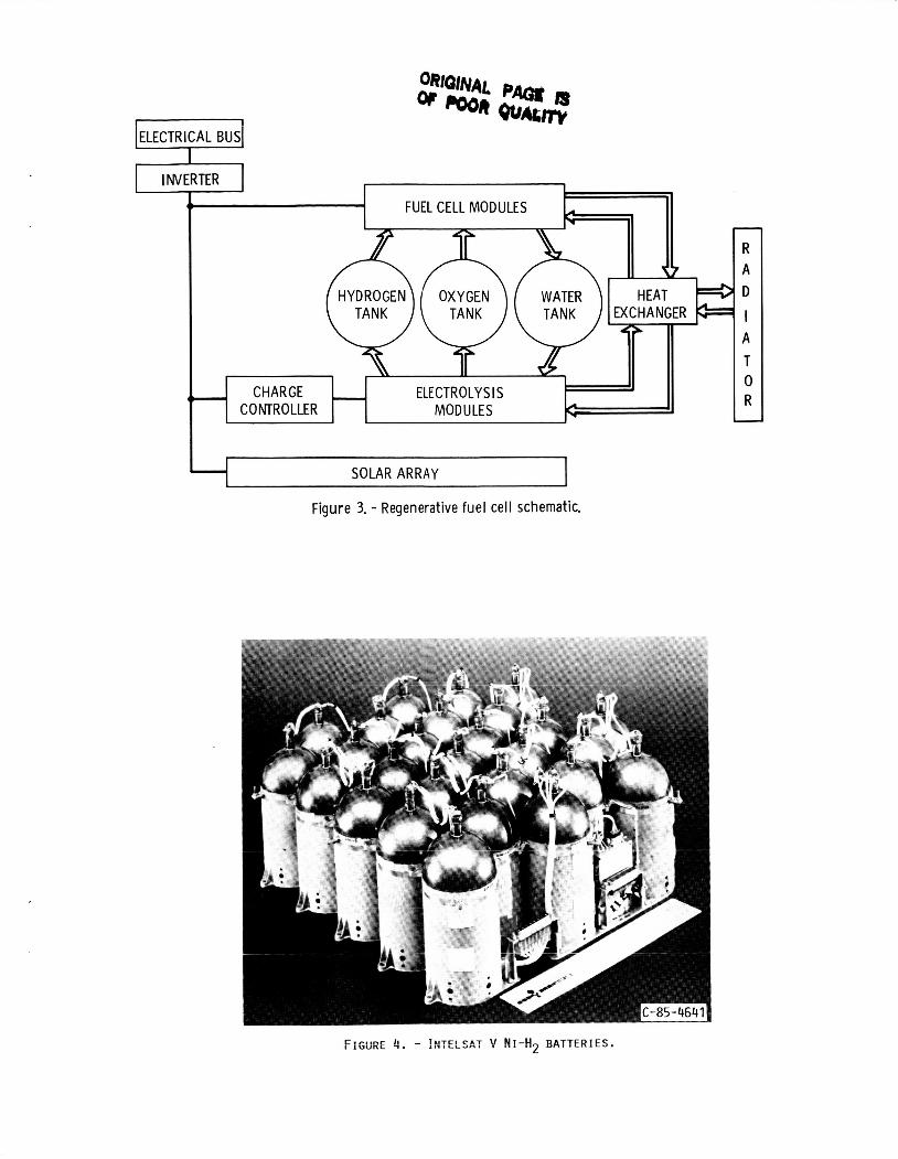
The RFC concept is shown schematically in figure 3. Excess electrical energy from the solar array is stored chemically by generating hydrogen and oxygen from water in the electrolyzer. the stored hydrogen ana oxygen. A hlgh degree of f:exlbiltty is inherent in
Electricity is generated by recombining
3

this approach. Changes in energy storage requirements (input and/or output) are easily accomnodated by changes in the size of the storage tanks. The RFC system is significantly lighter than battery systems, but is not as efficient nor as reliable. The fuel cell module shown in figure 3 is based on NASA- sponsored improvements to the International Fuel Cells Corporation technology currently in use on the STS orbiter. The electrolysis module is based on the alkaline static-feed technology under development by Life Systems, Inc. with support from NASA. Reliability of the complex RFC system was considered a major problem i n the platform trades (with the requirement of 3 yr on orbit before replacement or servicing) and was the primary reason for concentrating on batteries for platform use. For the station manned core, the RFC design was modularized into a number of orbital replacement units (ORU's) and redun- dancy was incorporated (weight not being as critical as on the platform) to achieve the required reliability.
Nickel-cadmium batteries were considered a prime candidate for energy storage. Their technology is well-established and mature. They currently provide energy storage for the majority of spacecraft, and they are produced in sizes up to 100 Ah in aerospace cell configurations. They have a long his- tory of successful performance, although at low depth-of-discharge (DOD) lev- els, thus have a correspondingly high mass penalty. Development risk for the nickel-cadmium battery assembly, however, was considered very low.
Two nickel-hydrogen battery options were considered: (1) the Individual Pressure Vessel (IPV) nickel-hydrogen battery type and (2) the bipolar nickel- hydrogen battery type. The IPV nickel-hydrogen system is currently i n use in spacecraft in geosynchronous Earth orbit (GEO). Space-qualified cells are available in cell sizes up to 50 Ah cell capacity and diameters of 3.5 in. Figure 4 shows the Intelsat V battery composed of 30 Ah nickel-hydrogen cells made by Eagle Picher Corporation. For station manned core and platform use i n low Earth orbit (LEO), there are considerably more charge/discharge cycles per year than in GEO. Endurance testing for the LEO regime has been initiated to verlfy five year life. Because higher cell capacity would reduce weight and cost, development effort is under way on increased capacity cells, using straight-forward extrapolation of existing components. Successful fabrication of single-stack 4.5-in. diameter cells has already been completed. The bipolar nickel-hydrogen system is also currently being developed. Demonstrations of subscale hardware and battery stacks have been accomplished. However, due to its low technical maturity, it was not carried into the final trade studies.
IPV nickel-hydrogen batteries were finally selected for the platform,
Their weight was about 50 percent of the nickel-cadmium battery based on considerations of weight, cost, reliability, and development risk/ schedule. weight and they were much lower in overall cost.
Based on inherent contingency for the station manned core, IPV nickel- hydrogen batteries were also selected. for the RFC system, at IOC, while only being slightly higher in 30-yr life cycle cost. tion. The extent of commonality, whether at the technology, development, cell, battery, and/or thermal control level, will be determined in the preliminary design activity. Such commonality is considered extremely important to reducing development, logistic, and sparing costs.
They yielded slightly lower costs than
Their use would permit commonality between the platform and sta-
4

SOLAR DYNAMIC TECHNOLOGY TRADES
While the photovoltaic technology is, in general, well-proven in space, solar dynamic (SD) technology offers advantages of efficiency and cost. The efficiency advantage derives from the higher efficiency of the engine (20 to 30 percent) as compared to silicon solar cell efficiency (about 14 percent), and the higher efficiency of thermal energy storage (over 90 percent) as com- pared to battery efficiencies of around 70 to 80 percent and regenerative fuel cell efficiencies of about 55 percent. The improved system efficiency of solar dynamic (SD) systems as compared to photovoltaic ( P V ) systems translates into less solar collection area, which results in reduced drag and less concern regarding station dynamics, approach corridors, and experiment viewing angles. The reduced drag is particularly important because it allows lower flight alti- tudes within given constraints of drag-makeup fuel and orbit decay time.
Two types of dynamic conversion cycles were considered: (1) the closed Brayton cycle (C8C) and (2) the organic Rankine cycle (ORC). The ORC system is shown schematically in figure 5. A parabolic mirror focuses the sun's rays through aperture of the heat receiver. Within the receiver, the concentrated solar flux vaporizes the organic working fluid (e.g., toluene). The hot vapor goes to the turboalternator at about 750 O F and after condensation is recycled by the pump. Within the receiver, there is a need for thermal energy storage to get through the eclipse period. Typically, salt (e.g., LiOH) is considered. This salt would melt during the sun period and would solidify during the shade period, heating the working fluid as it solidified.
In the CBC system, helium-xenon gas mixture is used as the working fluid in place o f the organic fluid. Since the fluid remains a gas in all regions of the flow loop, the pump becomes a compressor, there is no condensation required, and there are no potential low-gravity problems as might be the case for the ORC system which has both gas and liquid in its flow loop. The inlet temperature, however, of the gas to the turbine is considerably higher for the C8C system (about 1300 OF).
Because solar dynamic systems have not been used in space, there is higher risk in assessing costs, schedules, and power availability than for PV systems. There is, nevertheless, a strong technology base for the engines from terre- strial and aeronautical applications. ORC units i n sizes from a few kilowatts of power to several hundred kilowatts have been used in numerous terrestrial applications. Three kilowatt units with Dowtherm A as the working fluid have. accumulated over 150 000 hr of operation. Units of various sizes using toluene have accumulated over 100 000 hr. The applicable experience base for Brayton units (not closed cycle) include the hundreds of millions of hours of operating experience with aircraft gas turbine engines. Aircraft environmental control system turbine expanders using gas lubricated foil bearings have accumulated millions o f hours of operating experlence. These are similar in size to the turbine and gas bearing units evaluated for the station solar dynamic sub- system. Of particular significance, the NASA space power program in the 1960's achieved over 50 000 hr of test time (38 000 hr on one unit) for a space- designed, closed-cycle Brayton system using helium-xenon working fluid and gas- lubricated bearings. This unit was also tested in a complete flow loop system under space-simulated thermal vacuum conditions.
5
Rece i ve rs
The receiver, including the thermal energy storage, is a critical unit in
A the solar dynamic system. fabrication of a complete receiver for the NASA-Brayton space power system. successful test of three gas tubes with surrounding lithium fluoride thermal storage material was completed.
Some relevant experience was gained in 1962 by
For the station, the receiver for a 25 kWe solar dynamic subsystem will
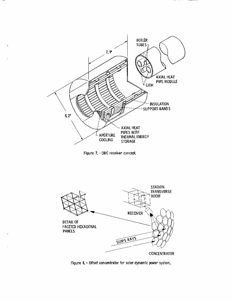
Concepts from the definition studies are shown in figures 6 be 2 to 3 m in diameter and length, depending on the type of system, salt, and particular design. (CBC) and 7 (ORC). The primary difference between the two designs is the use of a heat pipe concept, in the ORC case, to protect the toluene working fluid from hot spots that would cause thermal decomposition and breakdown of the to1 uene.
The Brayton cycle receiver concept shown in figure 6 is a cylindrical cavity lined with a series of tubes, running the length of the cavity, through which the working fluid (He/Xe) flows. Thermal energy storage (TES) is pro- vided by a melting/freezing salt enclosed in a series of annular shaped metal- lic containment rings surrounding the working fluid tubes. Currently, the salt selected is a eutectic mixture of lithium fluoride and calcium fluoride. The compartmentalization of the salt in the rings localizes the void formation on freezing so as to better maintain the desired heat transfer and reduce wall stresses due to salt expansion during melting. high temperature insulation which reradiates the incomdng energy to the back side of the tubes. Multifoil insulation surrounds this wall structure. ,
The cavity walls consist of
The organic Rankine cycle receiver shown In figure 7 utilizes axial heat pipes with integral TES. Heat pipes are used to provide heat flux leveling to accommodate solar flux maldistributions that could cause localized hot spots that would degrade the temperature sensitive organic working fluid (toluene). The heat pipes maintain a uniform, constant cavity temperature and a uniform temperature around the TES material (in this case, lithiurn hydroxide). The vaporizer consists of parallel flow tubes that run axially inside the heat pipes. and contain an orifice at the inlet to impose a large pressure drop, relative to the vaporizing section, to preclude flow imbalances. Under normal insola- tion, the concentrated solar flux is distributed over the length of the heat pipes, with higher heat loads at the end nearest the aperture. The heat pipe working fluid, potassium, is vaporized and distributes uniform heat to the cooler vaporizer and TES modules by condensing at these surfaces. The TES modules remain at a relatively constant temperature as latent melting occurs. During eclipse, solidification of the salt becomes the energy source and heat is transported away from the TES modules to the vaporizer tubes by the potas- sium.
They are manifolded together at the inlet and outlet of the heat pipes
Currently, while preliminary design has been Initiated on these two con- And, cepts, there is continuing effort to evaluate other promising concepts.
under the Space Station Advanced Development Program, work is under way both analytically and experimentally to address critical areas of the receiver design.
6

Concentrator
The technology base f o r t h e m i r r o r concentrator i s a l s o more l i m i t e d than f o r engines. There has been experience I n t e r r e s t r i a l programs sponsored by t h e Department o f Energy, b u t t he m i r ro rs were much more heav i l y const ructed s ince they had t o w i ths tand wind and g r a v i t y loads. The l i g h t w e i g h t concen- t r a t i n g m i r r o r f o r a space SD system can draw, however, upon the l a r g e space antenna technology.
Dur ing the d e f i n i t i o n studies, two bas ic concentrator concepts were se lec ted f o r in-depth evaluat ion, a f t e r e a r l y screening o f a v a r i e t y o f con- cepts: (1) s i n g l e r e f l e c t i o n (Newtonian) and (2) m u l t i p l e r e f l e c t i o n (Cassegrainian). The Newtonian concept has had t h e most a t t e n t i o n f o r t e r r e - s t r i a l a p p l i c a t i o n s due t o i t s s i m p l i c i t y . The Cassegrainian has been f a b r i - cated and success fu l l y used i n t e r r e s t r i a l app l i ca t i ons , a lso . Both types have been used i n space rf antenna designs. The Cassegrainian o p t i c a l con- f i g u r a t i o n was u l t i m a t e l y dropped from cons idera t ion , however, because o f t he need f o r a second r e f l e c t o r sur face w i t h a t tendant o p t i c a l r e f l e c t i v i t y losses, poss ib le shadowing losses, p o s s i b i l i t y o f increased p o i n t i n g e r r o r s ( o r need f o r increased s t i f f n e s s ) , and need f o r secondary m i r r o r coo l i ng ( increased complex i ty ) .
For the Newtonian system, a specia l case was examined and u l t i m a t e l y base- l i n e d . This was the o f f s e t r e f l e c t o r ( f i g . 8) . It cons is ts o f a segment o f the parent parabolo id , w i t h a r e l a t i v e l y sho r t f o c a l length, and mounted o f f s e t f rom the parent pa rabo l i c ax i s . The rece iver i s t i l t e d w i t h respect t o the parent parabo lo id a x i s t o opt imize the rece ive r c a v i t y heat f l u x d i s t r i b u t i o n . This concept has been success fu l l y used i n rf antenna app l i ca t i ons and has s i g n i f i c a n t reduced s t r u c t u r a l weight and moment o f i n e r t i a advantages over o ther concepts. The major disadvantage o f t h i s concept appears t o be unsym- m e t r i c a l f l u x e s w i t h i n t h e c a v i t y o f the rece iver .
One c r i t i c a l area o f t h e SD concentrator invo lved d e f i n i t i o n o f the gim- b a l i n g system. a va lue much t i g h t e r than f o r PV arrays. t u r a l dynamics, and gimbal system design a l l p lay a r o l e i n ach iev ing the requ i red accuracy. A number o f gimbal concepts were evaluated. The one f i n a l l y se lected invo lved t h e use of l i n e a r ac tua tors incorporated i n t o two o f t he th ree concentrator sur face support s t r u t s f o r f i n e po in t i ng , a long w i t h use o f a lpha and beta gimbals.
The m i r r o r must be pointed t o the sun w i t h an accuracy o f 0 . l o , Po in t i ng and t r a c k i n g c o n t r o l , s t ruc -
The design d e f i n i t i o n f o r the concentrator s t r u c t u r e and r e f l e c t i v e sur- face a l s o invo lved examination o f a la rge number o f concepts. The approach se lected consis ted o f a graphite-epoxy t r u s s framework conf igured as a hexa- gonal panel t h a t comprises a sec t i on o f t h e parabo lo ida l curve along i t s sur - face. This provides a support s t ruc tu re f o r a number o f t r i a n g u l a r g raph i te - epoxy face ts which a re conf igured w i t h a spher ica l surface. The graphi te-epoxy facesheet o f each f a c e t i s coated w i t h vapor-deposited s i l v e r o r aluminum along w i t h a p r o t e c t i v e coat ing. Seventeen (CBC) t o n ineteen (ORC) hexagonal panels comprise the t o t a l concentrator surface. The panels a re stacked f o r d e l i v e r y t o o r b i t and deployed t o form t h e pa rabo l i c surface. Panel a l ignment i s achieved w i t h l a t c h i n g mechanisms a t each panel i n t e r f a c e . A subscale model o f t h i s panel, deployment, and l a t c h i n g concept has been demonstrated.
7

Current Status
Both CBC and ORC power generating subsystems are being carried forward into preliminary design. Only through a more detailed evaluation can a decision between the two be made.
Performance and cost of the two are very close.
The CBC subsystem concept includes the receiver as shown in figure 6, an offset concentrator of graphite epoxy construction composed o f individual hex- agon panels with mirror facets on each panel, a rotating unit with a radial flow turbine and compressor, gas lubricated foil bearings, and a Rice-Lundell- type alternator. At the time of writing this paper, both segmented pump loop and multiple heat pipes were candidates for the radiator, and further analysis will be required for selection. The working fluid Is helium-xenon gas.
The ORC concept includes the receiver as shown in figure 7, an offset concentrator, an axial flow turbine driving a Rice-Lundell alternator and pitot pump, with tilted pad bearings lubricated by the toluene working fluid. radiator is a heat pipe concept (aluminum with ammonia). After examination of a number of working fluids, toluene was selected. Within the engine, there is a Rotary Fluid Management Device (RFMD) which is basically a low-speed pitot pump. It must operate in low gravity to ensure NPSH at the feed pump inlet, to separate noncondensable gases, and to control working fluid inventory. The condenser is a shear-controlled design utilizing converging passages to maintain adequate velocity and operation in low gravity.
The
POWER MANAGEMENT AND DISTRIBUTION TRADES
The power management and distribution (PMAD) subsystem has the general characteristics of a terrestrial utility power system. It must be user- friendly and accommodate changes in load type and size. Also, it must be adaptable to growth. The high power level (75 kWe initially, with growth capability to 300 kWe) dictates a higher distribution voltage than the 28 V commonly used on spacecraft. Distribution voltages up to 440 V were considered in the definition studies. principal candidates ended up as 20 kHz ac, 400 Hz ac, and dc. The dc approach has the advantage of familiarity, but ac offers greater flexibility (ease of providing different voltages) and is easier to switch than dc (the switching for ac can be accomplished at zero current). exist, such components at 150 Vdc and higher, designed for space (hence high efficiency), are lacking in technology.
A range of frequencies were also studied. The
While 28 Vdc components do
400 Hz is commonly used on aircraft, thus systems-level technology exists. However, technology is lacking for space-type components, although this is not considered a major problem. But, 400 Hz has a potential problem with acoustic noise and electromagnetic interference (EMI), particularly with respect to plasma coupling which can impact a number of plasma experiments planned for the station.
The 20 kHz high power, sine wave system has never been flown, but this concept is extremely attractive. Due to the high frequency, components are small, lightweight, and highly efficient, particularly when using series resonant conversion in dc/ac, ac/dc, dc/dc, or ac/ac converters. Space-type components have been designed and tested. A breadboard system has been
8
demonstrated. No problems w i t h acoust ic no ise e x i s t , and t h e EM1 i s considered a minor problem. s e l e c t i o n has no t been made, and both 400 Hz and 20 kHz a r e being f u r t h e r evaluated.
A t t h e t ime o f w r i t i n g t h i s paper, t he vo l tage and frequency
E l e c t r i c a l System Arch i tec tu re
The e l e c t r i c a l d i s t r i b u t i o n a r c h i t e c t u r e f o r t he s t a t i o n manned core i s shown i n f i g u r e 9. A dua l - r ing bus system prov ides u t i l i t y power t o each o f t en ex te rna l load areas on the upper keel and boom, lower kee l and boom, and t ransverse boom. Each bus i s ra ted f o r 1 5 kW. U t i l i t y power t o the r i n g d i s t r i b u t i o n system i s c o n t r o l l e d by the Main Bus Swi tch ing Assembly (HBSA) and i n t e r f a c e s t o the load through a Power D i s t r l b u t i o n and Contro l Assembly (PDCA). Each PDCA i s ra ted a t 10 kW and can support up t o 20-load connections. C r i t i c a l loads can be connected t o m u l t i p l e o u t l e t s f o r r e l i a b i l i t y .
The a r c h i t e c t u r e f o r t he e l e c t r i c a l d i s t r i b u t i o n system t o the manned modules i s shown i n f i g u r e 10. Each o f t he f o u r modules w i l l be suppl ied through two penet ra t ions . Transformers a re used a t t he module pene t ra t i on p o r t t o p rov ide i s o l a t i o n f o r a s ing le p o i n t ground. Present ly , each bus i s ra ted a t 30 kW. The d i s t r i b u t i o n w i t h i n the modules i s a l s o by a dual r i n g a r c h i t e c t u r e . Loads w i th in each module w i l l rece ive u t i l i t y power f rom a PDCA ( t o t a l o f f i v e PDCA's i n each U.S. module t o accommodate up t o 50 kW of load).
The PMAD system w i l l have a con t ro l system f o r sensing and comnand. I n the event o f a f a u l t i n the r i n g d i s t r i b u t i o n system, Remote Bus I s o l a t o r s (RBI 's ) loca ted I n the MBSA's and PDCA's w i l l remove t h r e s t o r e power through a l t e r n a t e connections. I f f a u l t s Remote Power C o n t r o l l e r s (RPC's) w i t h l n the PDCA's w i l l a c t t o p r o t e c t t h e power system.
The e l e c t r i c a l d i s t r i b u t i o n a r c h l t e c t u r e f o r t he p the above descr ibed s t a t i o n manned core a r c h i t e c t u r e , w t h e use o f a r a d i a l bus a r c h i t e c t u r e ra the r than a r i n g
f a u l t e d sec t i on and occur i n the loads, sense the f a u l t and
at forms I s s i m i l a r t o t h the except lon being bus.
SYSTEM STUDIES
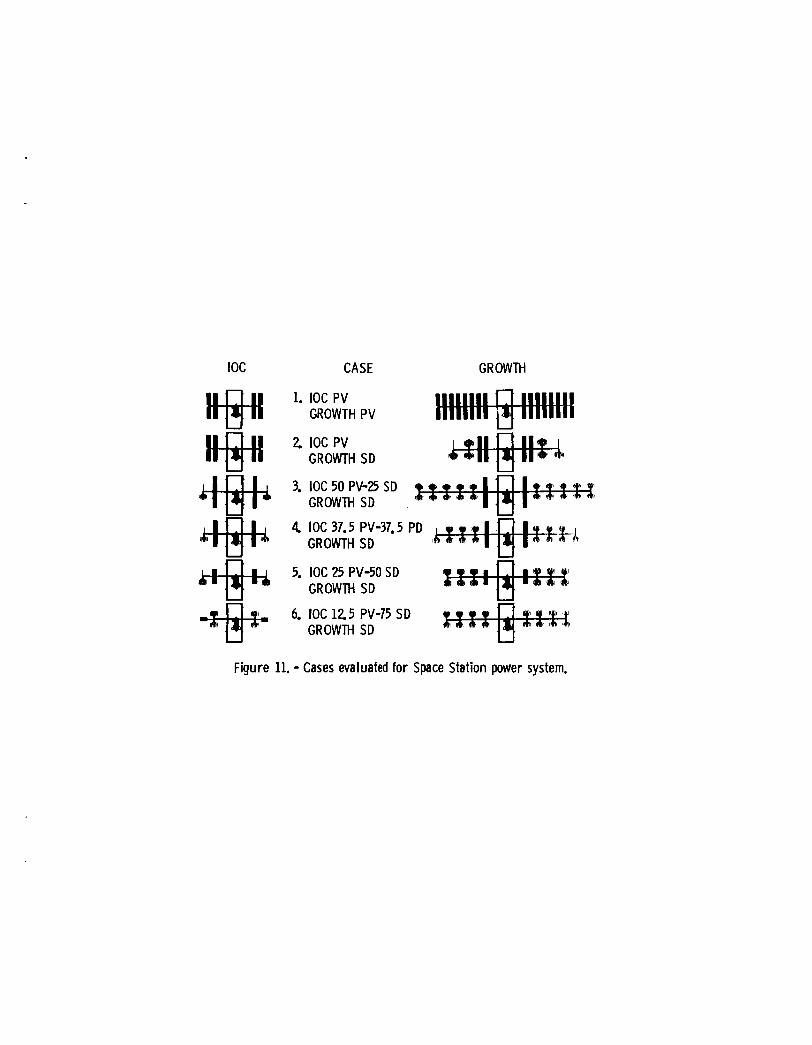
S i x bas ic cases were s tud ied f o r t he s t a t i o n manned core, as i nd i ca ted i n f i g u r e 11. Both t h e 7 5 kWe I O C con f igu ra t i on and t h e 300 kWe growth conf igur - a t i o n a r e shown. The cases range f r o m a l l PV (Case 1) t o a case w i t h maximum SD (Case 6), w i t h vary ing propor t ions o f SD t o PV f o r Cases 2, 3 , 4, and 5. A number o f v a r i a t i o n s were a l s o evaluated f o r each case t o evaluate commonality. For example, Cases 5 and 6 a re shown w i t h p l a t f o r m arrays, b u t Cases 3 and 4 were a l s o evaluated w i t h p l a t f o r m arrays I n a d d i t i o n t o the l a rge r , more o p t i - mum ar rays as shown. An a l l SD case, w i th no PV a r ray system, was n o t con- s idered p r a c t i c a l . Power i s needed dur ing s t a t i o n manned core assembly when sun t r a c k i n g i s no t e a s i l y accomplished (up t o about t h e f o u r t h launch). Only PV ar rays can produce power (al though a t a reduced l e v e l ) i n such circumstances.
9
In the final evaluation, an attempt was made to identify all factors Impacting cost and translate them into total cost of the program for the com- bined station manned core and platform. Both IOC cost and life cycle costs were evaluated. Included were power system hardware and software development, manufacturing, verification, overhead, and launch costs. The cost benefit to station manned core operation with increased shuttle capacity was also esti- mated for the SD systems, as would occur due to lower orbit altitude permis- sible with the SD systems which have lower drag. There was a considerable reduction in life-cycle costs credited to SD systems due to this effect.
The selected station manned core configuratlon was Case 5. The PV sub- system generates nominally 25 kWe using four platform wings and uses nickel- hydrogen batteries identical to those used on the platform. The SD subsystem generates nominally 50 kWe (the exact value depends on the preliminary design and the exact PHAD efficiencies). The SD power generation would be either a Brayton or Rankine system, dependent on results of the preliminary design effort. Either would use the off-set concentrator concept previously described.
CONCLUSION
The selected electrical power system meets the station and platform requirements for both IOC and growth. Indeed, it offers a balanced utility approach to the uncertainty associated with future loads. There will be more loads which are larger in power requirements and of different nature from those currently planned for the station and platform at IOC. The subsystem selections are based on a combination of minimum IOC costs and life cycle costs, along with low development and schedule risk. The selected hybrid system appears to best meet the programnatic and technical considerations driving the power system definition.
10
Average
Station manned core - IOC Growth
Peak
Polar platform - IOC Growth
75 300
8 15
6 1 23 Co-orbiting platform - IOC
Growth
100 350
16 24
6 I 23
TABLE 11. - PROGRAMMATIC/TECHNICAL CONSIDERATIONS ~~ ~
Initial cost Life-cycle cost Development risk Commonality Weight Maintainability Failure criteria Safety Veri f i cation
Schedule Orbit altitude and decay Growth capability Contingency requirement Load types and location Logistics and sparing Orbital assembly 8, buildup Interfaces Li f et i me
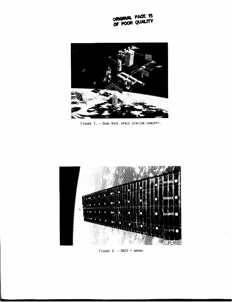
FIGURE 1. - DUAL-KEEL SPACE STATION CONCEPT.
FIGURE 2. - OAST-1 ARRAY.
I
SOLAR ARRAY
Figure 3. - Regenerative fuel cell schematic.

RECEIVER- h HEAT
FLUID 7
CONDENSER 7 RECUPERATOR STORAGE UNIT-
/ ----------, -------- \\ BOILER,
\
/ ‘\\\ 1 1 It;:
I1 ‘ I
II 1’ -------- ---------- \ \ \
1’1 I RADIATOR ‘\ \ \
1 , I ’ I ! I
/ /
P X P - /
1 / /
TURBINE PUMP
\/// CONCENTRATOR
Figure 5. - Solar organic Rankine cycle system schematic.
PCMl WORK ING FLUID
STRUCTURE y d ‘L TUBE SUPPORT BAFFLE
PHASE CHANGE / MATER I A L 7
‘\BRAZE BETWEEN RING AND TUBE
Figure 6. - Brayton receiver concept.
PIPES WITH
STORAGE APERTURE THERMAL ENERGY
Figure 7. - ORC receiver concept.
. STAT1 0 N
DETAIL OF FACETED HEXAGONAL PANELS
CONCENTRATOR
Figure 8. - Offset concentrator for solar dynamic power system.

Figure 9. - Ring distribution architecture.
/ \
\ , / LOG e . .
5-PDCAS
& 1 1 T . 2 0 8 V A C HAB
I I &208 VAC v
/ \
\ /
E SA
*208 VAC LAB *208 VAC
Figure 10. - Module architecture.
IOC CASE GROWTH
1. IOC PV
2 IOC PV GROWTH SD
3. IOC 50 PV-25 SD GROWTH SD
4 IOC 37.5 PV-37.5 PD
GROWTH PV
GROWTH SD e 5. IOC 25 PV-50 SD GROWTH SD
U U
6. IOC 1 2 5 PV-75 SD GROWTH SD
Figure 11. - Cases evaluated for Space Station power system.

1. Report No.
NASA TM-88824
9. Security Classif. (of this report)
Unclassified
2. Government Accession No.
20. Security Classif. (of this page) 21. No. of pages 22. Price’
Unclassified
a t l e and Subtitle
Electrical Power System Design for the U.S. Space Station
7. Author@)
Donald L. Nored and Daniel T. Bernatowicz
9. Performing Organization Name and Address
National Aeronautics and Space Admini strati on Lewis Research Center Cleveland, Ohio 44135
National Aeronautics and Space Administration Washington, D . C . 20546
2. Sponsoring Agency Name and Address
5. Supplementary Notes
3. Recipient’s Catalog No.
5. Report Date
6. Performing Organization Code
485-49-02 8. Performing Organization Report No.
E-3073 IO. Work Unit No.
11. Contract or Grant No.
13. Type of Report and Period Covered
Technical Memorandum 14. Sponsoring Agency Code
Prepared for the 21st Intersociety Energy Conversion Engineering Conference, cosponsored by the ACS, SAE, ANS, ASME, IEEE, AIAA, and AIChE, San Dlego, California, August 25-29, 1986.
6. Abstract
The multipurpose, manned, permanent Space Station will be our next step toward utilization of space. to its success. The power systems for the Space Station manned core and plat- forms that have been selected in definition studies are described in this paper. The selected system for the platforms uses silicon arrays and NI-Hz batteries. The power system for the manned core is a hybrid employing arrays and batteries identical to those on the platform along with solar dynamic modules using either Brayton or organic Rankine engines. technologies, and configurations that were considered, and the basis for selec- tion, are discussed.
A multikilowatt electrical power system will be critical
The power system requlrements, candidate
7. Key Words (Suggested by Author@))
Space station; Hybrid power system; Photovoltaic system; Solar dynamic system; Power management and dlstribution
18. Distribution Statement
Unclassified - unlimited STAR Category 20
‘For sale by the National Technical Information Service, Springfield, Virginia 22161


![LPV hard constraints IJCAS resubmit3 · nored, such as space telescope pointing [21] and machine tool control. For both interpretations, a solution to the OCC control problem results](https://img.pdfslide.net/doc/110x75/5e78dde83dbdfd0f59138701/lpv-hard-constraints-ijcas-resubmit3-nored-such-as-space-telescope-pointing-21.jpg)


![Forecasting Interactive Dynamics of Pedestrians With ......model, however, focused only on trajectory data. They ig-nored the rich information underlying the visual data. In [24, 18],](https://img.pdfslide.net/doc/110x75/6122c78b76f52874a269cea0/forecasting-interactive-dynamics-of-pedestrians-with-model-however-focused.jpg)